

Page 1
MANUALE DI ISTRUZIONI
SYSTEM
MLK 165
COMP
ML 165
www.hertzaudiovideo.com
OWNER’S MANUAL
Electro - Acoustic parameters
62018 Potenza Picena (MC) Italy - T +39 0733 870 870 - F +39 0733 870 880 - www.elettromedia.it
D
mm
Xmax
mm
Re
ohm
Fs
Hz
Le
mH@1kHz
Le
mH@10kHz
Vas
lit
Mms
gr
Cms
mm/N
BL
T-m
Qts
Qes
Qms
Spl
dB
ML 28
big chamber
ML 28
small chamber
ML 280
small chamber
ML 500R ML 1600 ML 165ML 280
big chamber
28
-
3,0
920
0,75
0,04
-
-
-
-
0,41
0,90
0,75
91
28
-
3,0
1200
0,69
0,04
-
-
-
-
1,09
1,86
2,65
91
28
-
3,0
930
0,78
0,04
-
-
-
-
0,40
0,90
0,72
91
28
-
3,0
1100
0,98
0,05
-
-
-
-
1,21
1,96
3,14
91
-
-
7,5
370
-
-
-
-
-
-
-
-
-
93
128
6
3,1
71
0,67
0,11
6,82
17,1
0,29
7,23
0,41
0,44
5,46
93
128
6
3,1
59
0,72
0,31
9,90
17,1
0,42
5,64
0,54
0,62
4,37
92
06.1
Page 2
02 03
Introduction
Italiano
GLI ALTOPARLANTI HERTZ MILLE SONO IN GRADO DI CREARE SISTEMI AUDIO AD ALTA
POTENZA CHE POSSONO GENERARE ELEVATISSIME PRESSIONI SONORE INDISTORTE.
RICORDATE CHE PROLUNGATE ESPOSIZIONI AD UN LIVELLO ECCESSIVO
DI PRESSIONE ACUSTICA POSSONO PRODURRE DANNI AL VOSTRO UDITO; UTILIZZATE
DUNQUE EQUILIBRIO E BUON SENSO NELL’ASCOLTO.
La sicurezza durante la marcia deve restare sempre al primo posto. In ogni situazione il volume
d’ascolto deve avere un livello tale da non coprire i rumori provenienti dall’esterno; dovreste essere
in condizione di udire anche quelli del Vostro veicolo per affrontare prontamente situazioni
di emergenza.
Per ottenere il massimo delle prestazioni dal Vostro nuovo sistema di altoparlanti Vi consigliamo
di seguire attentamente le istruzioni del presente manuale. La realizzazione di un sistema hi-fi car
di alto livello richiede una buona conoscenza delle problematiche meccaniche ed elettriche delle
autovetture; qualora riteneste di non possedere gli attrezzi necessari o la conoscenza adeguata,
non esitate a contattare un installatore specializzato. Un’installazione a regola d’arte Vi assicurerà
prestazioni entusiasmanti e coinvolgenti, senza influire sulla sicurezza e l’affidabilità della Vostra
autovettura.
Questo manuale è stato redatto per fornire le indicazioni principali e necessarie all’installazione e
all’uso del sistema. La varietà delle applicazioni possibili è tuttavia molto ampia; per avere ulteriori
informazioni non esitate a contattare il Vostro rivenditore HERTZ o l’assistenza ufficiale HERTZ
via mail, scrivendo direttamente agli indirizzi:
Per l’Italia - supporto.tecnico@elettromedia.it
Per l’estero - support@elettromedia.it
Gentile cliente,
complimenti per aver acquistato un prodotto HERTZ MILLE. La nostra soddisfazione è il primo
requisito cui devono rispondere i nostri prodotti: la stessa soddisfazione di chiunque voglia vivere
l’emozione del car audio.
Indice
SAFE SOUND
Indice
Presentazione
Technology
Esempi di installazione
Montaggio ML 165
Montaggio ML 28
Connessioni
Esempi serie-parallelo
Taratura
Utilizzo del controllo di livello del tweeter
Precauzioni Generali
Limiti di garanzia
Technical specifications
02
03
04
05
10
11
12
16
18
19
21
22
23
24
Page 3
Italiano
04 05
Technology
ML 28
ML 165
MLCX 20
La linea MILLE ha rivoluzionato il mercato sin dalla sua introduzione nel 1999.
Altoparlanti progettati per divenire il nuovo riferimento e soddisfare le richieste degli appassionati
più esigenti con prestazioni eccezionali.
Questi componenti hanno stabilito un nuovo standard nella riproduzione del suono, riscuotendo un
entusiastico apprezzamento del pubblico e prestigiosi riconoscimenti della
stampa specializzata.
L’innovazione e lo sviluppo continuo dei prodotti sono da sempre punti
di riferimento del programma di ricerca Elettromedia per HERTZ.
Oggi il team di Ricerca e Sviluppo è riuscito nell’impresa di migliorare ciò che
sembrava già perfetto.
La passione ci spinge alla ricerca di prodotti estremi, dove l’unico requisito
di fondo è la qualità, senza alcun tipo di compromesso.
Al servizio del suono per un’esperienza unica ed emozionante.
Technology
Nei laboratori Elettromedia la tradizione supporta la forza dell’innovazione.
I materiali utilizzati per la membrana del woofer e la cupola del tweeter sono creati dalla natura e
vengono trattati secondo processi affinati nel corso di decenni. Per l’ML 165 sono stati realizzati,
analizzati e valutati più di 35 materiali diversi per composizione delle fibre di cellulosa e materiali
impregnanti. Per l’ML 28 La fibra utilizzata è un impasto di cotone e seta in percentuali controllate
con doppio trattamento impermeabilizzante. Nessun altra membrana in metallo, fibra rigida o
sandwich di materiale composito è in grado di fornire un tale livello di rigidità, smorzamento e
leggerezza.
Le membrane dei componenti della linea MILLE sono state sviluppate mediante utilizzo dei più
avanzati software di modellazione a elementi finiti (FEM) e testate mediante prototipazione, misure
e ascolto tecnico. Questo processo permette di controllare ogni stadio del progetto e di verificarne
costantemente l’evoluzione.
La cupola dell’ML 28 segue un profilo esclusivo: emisferico nella prima sezione, iperbolico verso la
sommità. Il delicato rapporto tra diametro di emissione, altezza della membrana e profilo della
sospensione esibisce una frequenza di risonanza molto bassa e una dispersione del componente
regolarissima. Il V-Cone, come nell’ML 1600, ha un profilo esponenziale innovativo e approssima
l’andamento ideale. Il punto di contatto con la bobina mobile utilizza un leggerissimo supporto in
cellulosa, che ottimizza l’accoppiamento meccanico e il raggiungimento della massima prestazione
in potenza.
grigliaML 165
Page 4
06 07
Italiano
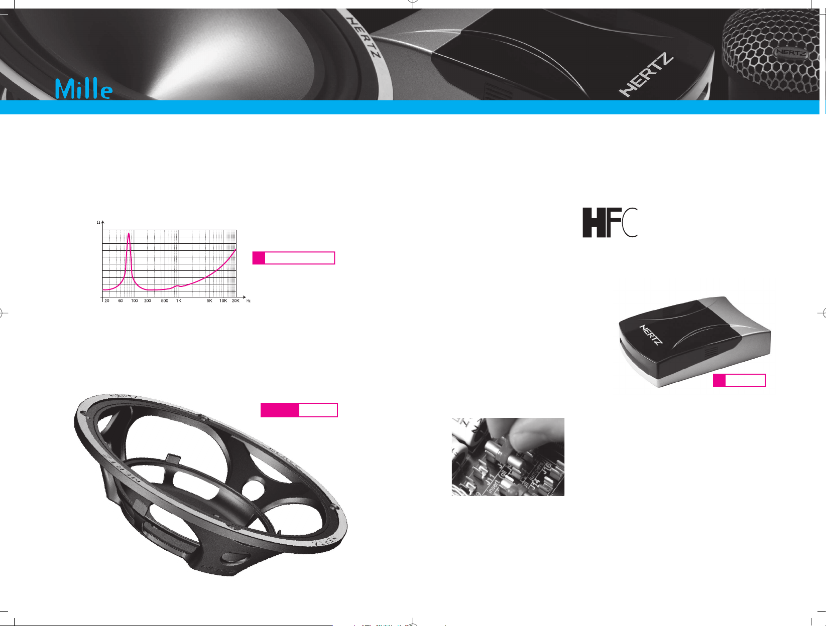
Simulazione FEM del gruppo magnetico
ML 28
Technology
Il gruppo magnetico di un midwoofer ad alta escursione deve rispettare diversi parametri di
fondamentale importanza: simmetria del flusso magnetico nei dintorni del traferro, intensità ed
ampiezza del campo, compattezza e leggerezza. Questi sono alcuni tra i fattori di vitale importanza
per l’ottenimento delle più alte prestazioni. Il massiccio motore dell’ML 165 racchiude queste
caratteristiche assicurando un’altissima stabilità termica ed una dinamica esplosiva.
Ogni dettaglio viene sottoposto ad analisi e valutazioni approfondite. Lo sviluppo dei gruppi
magnetici dei componenti MILLE si è avvalso di avanzatissime tecnologie di modellazione Finite
Elements Modellin.
Il tweeter ML 28 utilizza un doppio magnete in neodimio e ferro a bassissima percentuale di
carbonio, sviluppato appositamente per questo trasduttore. La geometria del gruppo magnetico
crea un campo d’induzione di 1.6 Tesla, con una perfetta simmetria di linee. L’escursione
meccanica di questo componente è limitata, ma le accelerazioni sono brucianti.
Semplificare il lavoro di installazione significa raggiungere prestazioni eccezionali anche in condizioni
critiche, senza la necessità di lavori di adattamento delle autovetture che spesso costringono a
stravolgerne gli interni.
Il carico acustico offerto alla parte posteriore della cupola di un tweeter ne influenza pesantemente
le prestazioni, esattamente come accade per un midrange o un woofer di grande diametro. Una
geometria tradizionale crea forti asimmetrie di movimento, poiché la membrana vede nel lato
anteriore uno spazio libero, mentre il lato posteriore è caricato dal ridottissimo volume che si forma
tra il polo centrale e la cupola.
Nell’ML 28 sono sta disegnati otto condotti di accordo che generano un accoppiamento privo di
risonanze con le camere di smorzamento posteriori. Le proporzioni dei volumi, dei passaggi e il
particolare materiale fonoassorbente posizionato all’interno offrono uno smorzamento ottimale
all’equipaggio mobile, per un suono naturale, limpido e dinamico. Sotto la cupola è posizionato un
secondo tipo di materiale acustico, più denso ed efficace alle alte frequenze, che ricalca il profilo
posteriore della membrana. Questo particolare elimina le ultime risonanze residue e genera una
gamma altissima dotata di dettaglio e naturalezza assolutamente sorprendenti.
Esploso del gruppo magnetico
ML 28
Sezione
ML 28
Risonanze ML 28
Risonanze Tweeter tradizionale
Page 5
Italiano
08 09
Technology
0
8
16
24
32
40
Woofer tradizionale
Ogni elemento dell’altoparlante contribuisce alla produzione del suono. Il cestello offre la geometria
di sostegno all’equipaggio mobile e al magnete e contribuisce all’emissione acustica attraverso
i propri modi di vibrazione e le riflessioni generate dalle razze posteriori. Le risonanze meccaniche di
un cestello tradizionale, solitamente comprese tra 800 e 1300 Hz (a seconda della massa e della
rigidità), assorbono preziosa energia che dovrebbe essere trasmessa unicamente alla membrana.
Per il nuovo ML 165 è stato applicato lo stesso cestello, totalmente inerte, dell’ML 1600. Il disegno
autoportante e l’utilizzo di una lega di alluminio leggera e smorzata stabiliscono un nuovo primato
per trasparenza acustica e il suono risulta preciso e neutro, totalmente privo di risonanze e
colorazioni indesiderate. Il look di questo altoparlante è incredibilmente accattivante e innovativo.
L’interno delle autovetture è uno degli ambienti più complessi e delicati per la riproduzione musicale.
Ogni abitacolo ha un suono particolare, richiede soluzioni di installazione specificamente dedicate e
la risoluzione di differenti problemi come il rapporto tra suono diretto e suono riflesso, la posizione
reciproca dei vari altoparlanti del sistema e la loro distanza e angolazione rispetto al punto di ascolto.
La possibilità di scegliere tra differenti configurazioni e
l’estrema versatilità dei crossover MILLE hanno posto
come imperativo lo sviluppo di un sistema di commutazione
semplice da utilizzare, affidabile nel tempo e in grado di
garantire un contatto di qualità altissima. I selettori EJ
(Easy Jumper) offrono un’ergonomia del tutto naturale
e prestazioni acustiche assolutamente trasparenti.
Nei sistemi di altoparlanti della linea MILLE, Elettormedia con HERTZ si è posta come unico
obiettivo il raggiungimento di prestazioni di livello assoluto, senza alcun compromesso dettato da
limiti economici o strutturali. Per ottenere questo risultato abbiamo progettato degli altoparlanti
estremamente avanzati per contenuti tecnologici, materiali impiegati e prestazioni acustiche, ed
abbiamo sviluppato nei nostri laboratori dei filtri di crossover innovativi ed eccezionali per realizzazione
e prestazioni.
MLCX 20
Un problema che deriva dall’asimmetria dell’ambiente CAR è il differente
orientamento degli altoparlanti dei due canali dal punto di ascolto.
La maggiore angolazione del canale più vicino all’ascoltatore
modifica la risposta in frequenza in relazione alla
superficie e alle dimensioni della membrana
radiante. Il sistema HFC (High Frequency
Contour) rende il suono dei canali rispetto al
punto di ascolto assolutamente sovrapponibile.
L’immagine acustica si stabilisce al centro
del cruscotto e la sensazione di ascolto è coerente,
solida, reale.
cestelloML 165
Page 6
Italiano
10 11
Installation Patterns
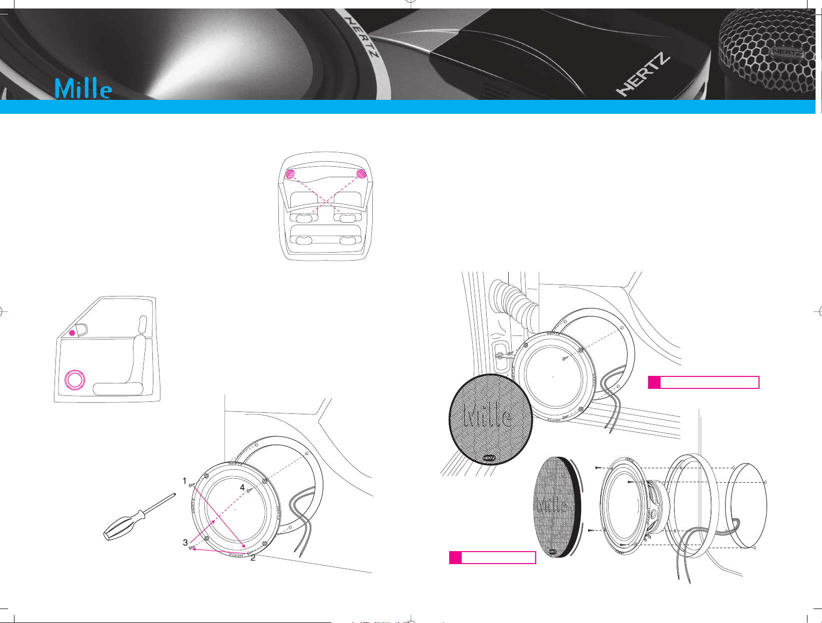
Montaggio ML 165
- Assicuratevi che i fori per le viti abbiano una buona tenuta.
- Il supporto della griglia, quando utilizzata, va inserito tra il piano di montaggio e il cestello
dell’altoparlante.
- Curate l’accoppiamento meccanico tra piano di fissaggio e altoparlante: interponete, quando
possibile, la guarnizione di tenuta ed eliminate eventuali sfiati presenti ai lati del cestello che
potrebbero creare un cortocircuito acustico riducendo le prestazioni del sistema.
- Nelle realizzazioni particolarmente complesse o con elevate potenze applicate, è indicato
effettuare un trattamento insonorizzante delle portiere che accolgono gli altoparlanti.
- Smorzate le vibrazioni delle superfici metalliche e dei pannelli in materiale plastico con pannelli
FONOMAT o con il trattamento specifico FONOGEL 100 di AZ audiocomp. Isolate le vibrazioni
di cavetteria e particolari meccanici mediante il mastice FONOSEAL 100.
- I tweeter dovrebbero essere posizionati all’altezza del viso
degli ascoltatori, mantenendo da questo la stessa
distanza del woofer; solitamente un buon compromesso
è il montaggio nel triangolo degli specchietti retrovisori
o sul montante del parabrezza.
- Fissate gli altoparlanti con tutte le viti in
dotazione serrandole gradualmente e a
croce.
Esempi di installazione
Nell’installazione di un altoparlante MILLE Comp è importante
tenere conto di alcuni accorgimenti:
- Per assicurare il miglior suono, gli altoparlanti di ciascun canale
(Left e Right) dovrebbero essere posizionati alla massima
distanza reciproca sia se montati sulle portiere anteriori che sul
cruscotto o sulla cappelliera.
- Posizionate i tweeter in modo che il loro asse di emissione si
incroci al centro dell’abitacolo.
Montaggio in predisposizione
Montaggio in portiera
Page 7
Italiano
12 13
Installation Patterns
Camera piccola
Camera grande
0
2
1
3
4
100 500 1k 5k 10k 20k 40k Hz
6
8
10
60
70
80
90
100
dB
0
2
1
3
4
100 500 1k 5k 10k 20k 40k Hz
6
8
10
60
70
80
90
100
dB
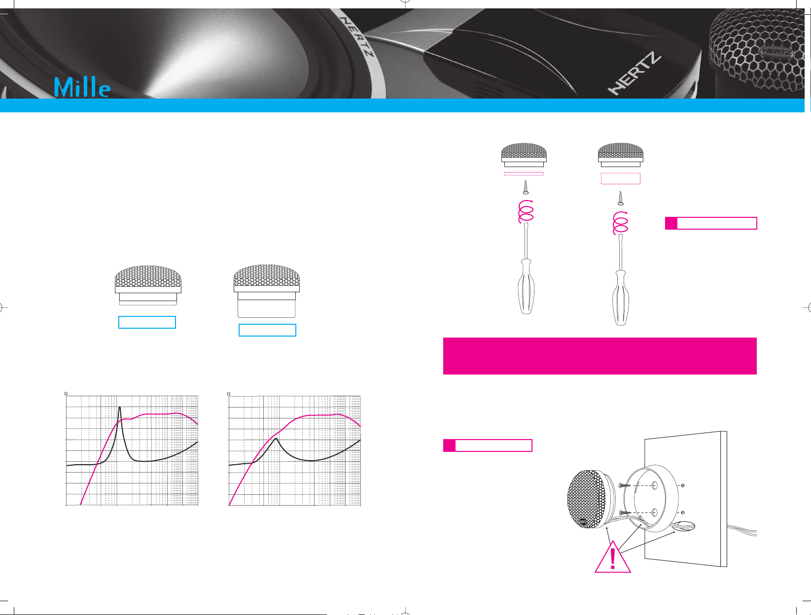
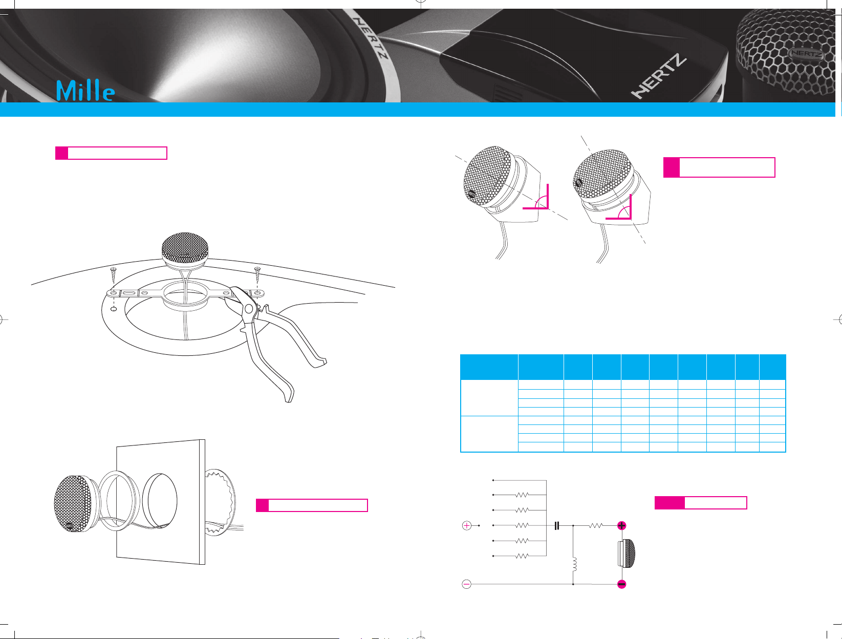
Montaggio ML 28
I tweeter ML28 hanno due camere acustiche in dotazione, rimuovibili e intercambiabili in pochi
secondi. Questa soluzione tecnica fornisce il miglior rendimento da ogni tipologia di installazione. Il
tweeter può essere utilizzato in differenti modi di funzionamento potendo scegliere il Q totale più
adatto al sistema semplicemente cambiando la camera di carico posteriore. Le camere simulano il
funzionamento in cassa chiusa e sono riempite di fonoassorbente realizzato con materiale naturale
non tessuto per il miglior smorzamento del componente. La Small Chamber aumenta il fattore di
merito rendendo la risposta del tweeter più ripida e molto definita alla frequenza di risonanza,
mentre la Big Chamber estende la risposta in modo più dolce verso le frequenze più basse.
La soluzione Small Chamber ottimizza il
suono in caso di installazioni con ridotta
profondità di montaggio.
La soluzione Big Chamber offre la massima
estensione in media frequenza e uno
smorzamento superiore a fronte di un
ingombro maggiore.
- Fissate con le due viti apposite
il supporto, praticate un foro
per il passaggio del cavo e
inserite il tweeter nel supporto.
Nota Bene: il montaggio con
accessorio a superficie richiede
l’utilizzo del tweeter senza alcuna
camera posteriore.
Montaggio a superficie
Montaggio delle camere
Attenzione
- Fissate sempre le due camere mediante le viti dedicate.
- Mantenete sempre nelle camere il materiale fonoassorbente preinserito.
- Non rimuovete la retina di protezione fissata nel retro del tweeter.
- Non rimuovete la griglia anteriore di protezione della cupola.
Page 8
Italiano
14 15
Installation Patterns
Components
Cut-off R1 R2 R3 R4 R5 R6 C1 L1
frequency ohm ohm ohm ohm ohm ohm uf mH
1
1
1
1
1
1
1
1
1,8
1,8
1,8
1,8
1,8
1,8
1,8
1,8
2,7
2,7
2,7
2,7
2,7
2,7
2,7
2,7
3,9
3,9
3,9
3,9
3,9
3,9
3,9
3,9
4,7
4,7
4,7
4,7
4,7
4,7
4,7
4,7
1
1
1
1
1
1
-
10,0
6,8
4,7
2,2
12,2
6,8
4,7
2,2
0,33
0,22
0,22
0,15
0,47
0,33
0,22
0,15
ML 28
Small Chamber
ML 28
Big Chamber
2000 Hz
2800 Hz
3500 Hz
5000 Hz
1800 Hz
2500 Hz
3500 Hz
5000 Hz
0 dB
-1,5 dB
-3 dB
-4 dB
-5 dB
-6 dB
R1
R2
R3
R4
R5
R6C1
L1
30°
60°
Di seguito troverete uno schema in forma semplificata con alcune soluzioni di filtraggio consigliate
per frequenze di incrocio standard. Lo schema e i valori sono stati progettati esclusivamente per il
tweeter ML 28. Ricordiamo che il filtro del tweeter deve essere integrato con quello del midwoofer
per ottenere una risposta complessiva regolare e omogenea. Pertanto tale filtro non va preso
come riferimento assoluto in sistemi completi, ma implementato con l’intero progetto.
- Fissate dal retro il supporto mediante
l’anello metallico fornito in dotazione
Montaggio a filo del pannello
- L’apposita staffa permette il montaggio del tweeter in predisposizioni standard per
87 mm e 100 mm. Rimuovete con le pinze la parte di staffa in eccedenza a seconda del diametro
della predisposizione.
Montaggio in predisposizione
- Il supporto a bicchierino con doppia
angolazione permette il montaggio in
due differenti posizioni su superfici
piane o lievemente convesse.
Nota Bene: l’utlizzo del supporto
inclinato richiede il montaggio della
camera piccola.
Montaggio a superficie con
supporto inclinato
Schema elettrico
ML 28
Page 9
Italiano
16 17
Installation Patterns
MLCX 20 Mono-Wiring
MLCX 20 Bi-Wiring
OTHER
CHANNEL
MONOBI
OTHER
TWEETER
OTHER
WOOFER
MONOBI
TW LEVEL
-4,5 dB
-3 dB
0 dB
-1,5 dB
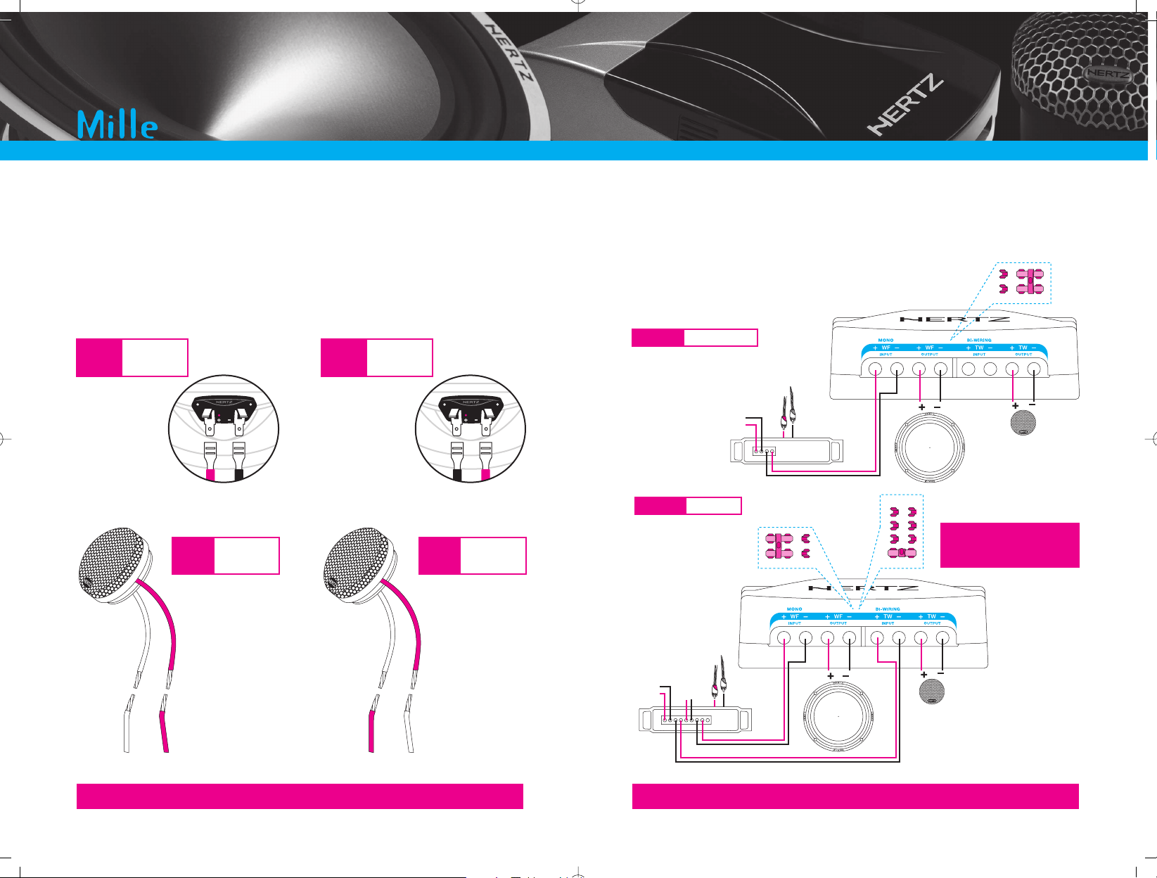
Connessioni
Utilizzate il filtro MLCX 20 in dotazione al sistema per collegare gli altoparlanti. Rispettate la polarità
indicata. Sul woofer ML 165 il polo positivo è contrassegnato sui terminali dal segno “+” e da un
punto rosso. Il polo positivo del tweeter ML 28 è indicato dalla treccia in rame puro. Se avete
intenzione di pilotare il sistema con una multiamplificazione attiva, dotata cioè di filtri elettronici,
ricordate di utilizzate il tweeter con un crossover passa alto con frequenza di taglio non inferiore a
1.8 kHz con pendenza di 12 dB Oct.
I filtri crossover della linea MILLE sono stati progettati per consentire sia la singola che la
multi-amplificazione. Mediante il semplice spostamento di alcuni selettori o il collegamento degli
appositi morsetti è possibile adattare il funzionamento del filtro a differenti tipologie di impianto.
Con la multi-amplificazione dei sistemi MILLE sarà possibile ottenere sistemi audio ad elevatissimi
valori di SPL, con una dinamica esplosiva.
Spegnere l’impianto di riproduzione prima di effettuare modifiche al collegamento.
Attenzione
La fase della connessione di tutti i componenti è determinante ai fini del risultato acustico.
Controllate che tutte le fasi siano corrette, come da indicazioni.
Attenzione
ML 28
Collegamento
elettrico
in controfase
ML 28
Collegamento
elettrico
in fase
ML 165
Collegamento
elettrico
in controfase
ML 165
Collegamento
elettrico
in fase
Posizionare i controlli TW Level
su 0 dB e regolare il livello
di emissione tramite
l’amplificatore dedicato
Attenzione
Page 10

Italiano
18 19
Tuning
Potenza applicata
Diametro del cavo
Lunghezza del collegamento
MLCX20 HFC
ON
HFC
®
OFF
HFC
ON OFF
HFC
ON OFF
Dimensionamento del cablaggio
Il cablaggio di potenza riveste un ruolo importante poichè influenza direttamente il fattore di
smorzamento del sistema e la qualità del suono; nella tabella allegata potete trovare una
indicazione della sezione del cavo, consigliata in funzione della lunghezza e della potenza
applicata.
La tavola si riferisce alla potenza
continua su un carico di 4 ohm.
Qualora il carico scenda, si dovranno
aumentare proporzionalmente le
dimensioni del cavo.
Esempi serie-parallelo
Di seguito riportiamo alcuni esempi di connessioni: singola, in parallelo e mista.
Taratura
Una volta terminata l’installazione in vettura e verificate tutte le connessioni occorre dedicare
alcune attenzioni alla messa a punto dell’impianto, alla taratura dell’amplificazione specifica
(se presente) e alla regolazione dei controlli HFC.
In condizioni di installazione standard, il differente posizionamento dei canali Left e Right rispetto al
punto di ascolto produce un’alterazione in ampiezza e fase del segnale percepito. In questo modo
si perde energia sulle frequenze alte. Se volete ottimizzare la risposta per il guidatore selezionate i
ponticelli del crossover di sinistra su HFC ON e quelli del crossover di destra su HFC OFF.
La risposta del canale sinistro verrà compensata e l’immagine acustica percepita dal guidatore
acquisterà una timbrica corretta, naturalezza e potenza.
spegnere l’impianto di riproduzione prima di effettuare modifiche al posizionamento dei jumper
sul circuito stampato
Attenzione
Page 11

Italiano
20 21
Tuning
Flat
Loudness
NO OK
TW LEVEL
-4,5 dB
-3 dB
-1,5 dB
0 dB
TW LEVEL
-4,5 dB
-3 dB
-1,5 dB
0 dB
Gli altoparlanti MILLE hanno una risposta
corposa e lineare e non necessitano di
equalizzazioni che potrebbero portare
l’amplificatore a saturazione o distorsioni spurie.
Evitate l’utilizzo del Loudness o di equalizzazioni
eccessive in gamma audio.
Una correzione di +3 dB nella risposta in
frequenza richiede all’amplificatore una potenza
raddoppiata nella banda interessata,
aumentando i rischi di distorsione.
Utilizzate, se possibile, il filtro subsonico settando
la frequenza di taglio nei dintorni dei 25 Hz.
Taratura
Il livello del gain dell’amplificatore (se utilizzato) dovrebbe essere regolato in modo da mantenere
sempre la sezione di potenza in una zona di funzionamento lineare, senza distorsioni o saturazioni
che potrebbero danneggiare l’altoparlante. Se l’amplificatore è dotato di un dispositivo che segnala
la distorsione, regolate il guadagno in modo che con il volume della sorgente a tre quarti della
scala, il led si accenda soltanto nei picchi di segnale.
Utilizzo del controllo di livello del tweeter
Il crossover è dotato di selettori EJ (Easy Jumper) per il controllo della sensibilità del Tweeter.
Il livello di emissione può essere regolato in una gamma dinamica di 4,5 dB.
Si consiglia di posizionare il punto centrale di controllo a -3 dB in caso di di installazione dei
tweeter sul triangolo dello specchietto retrovisore o a montante.
In caso di installazione dei tweeter a cruscotto o in portiera posizionare il punto centrale del
controllo a -1.5 dB.
Selezionate il posizionamento degli EJ a seconda dei gusti personali e della musica ascoltata.
Gain regolati più bassi
Led che lampeggiano
Amplificatore
in funzionamento
lineare
Gain al massimo
Led sempre accesi
Amplificatore
in distorsione
MLCX20 TW Level
Spegnere l’impianto di riproduzione prima di effettuare modifiche al posizionamento dei jumper sul
circuito stampato
Attenzione
Page 12

Italiano
22 23
Warning
Precauzioni Generali
• Il simbolo a lato indica che è opportuno prestare attenzione alle
indicazioni riportate. La mancata osservanza di tali istruzioni
potrebbe causare lesioni involontarie o danni all’apparecchio.
• Prima di procedere all’installazione leggete con attenzione tutte
le indicazioni contenute in questo manuale.
• Per facilitare l’installazione schematizzate nel dettaglio la configurazione dei Vostri nuovi
altoparlanti e realizzate un cablaggio ordinato e razionale.
• Indossate sempre occhiali protettivi durante l’utilizzo di attrezzi che possono generare schegge o
residui di lavorazione.
• Riponete, quando è possibile, il prodotto nell’imballo durante l’installazione per evitare danni
accidentali.
• Fissate alla struttura del veicolo in modo solido e affidabile tramite staffe, viti, dadi e bulloni tutte
le strutture supplementari realizzate per installare i vari componenti, per assicurare stabilità e
sicurezza in condizioni di marcia.
• Il distaccamento dal fissaggio durante la marcia dell’autovettura può causare grave danno per le
persone trasportate e per gli altri veicoli. Fissate adeguatamente gli altoparlanti, facendo la
massima attenzione nel caso in cui l'installazione sia all'interno dell'abitacolo.
• Non realizzate alcun tipo di installazione all'interno del vano motore.
• Prima dell’installazione, spegnete la sorgente e tutti gli apparati elettronici del sistema audio per
evitare qualsiasi possibile danno.
• Assicuratevi che il posizionamento prescelto per i componenti non interferisca con il corretto
funzionamento di ogni dispositivo meccanico o elettrico della vettura.
• Evitate di passare i cavi o installare gli altoparlanti in prossimità di centraline elettroniche.
• Prestate estrema attenzione nel praticare fori o tagli sulla lamiera, verificando che sotto o nella
zona interessata non vi sia alcun cavo elettrico o elemento strutturale e vitale per l’autovettura.
• Il cavo di collegamento deve essere provvisto di isolamento meccanicamente resistente ed
autoestinguente alla fiamma. La sezione del cavo deve essere dimensionata come quanto
suggerito nel presente manuale. Nel posizionamento, evitate di schiacciare il cavo contro parti
taglienti o nella vicinanza di organi meccanici in movimento. Assicuratevi che sia adeguatamente
fissato per tutta la sua lunghezza.
• Proteggete il cavo conduttore con un anello in gomma se passa in un foro della lamiera o con
appositi materiali se scorre vicino a parti che generano calore.
• Non fate passare mai i fili all’esterno del veicolo; non avreste protezione sufficiente contro l’usura
o in caso d’incidente.
• Nell'installazione degli altoparlanti e dei cavi che li collegano, accertatevi che non vadano in
contatto, anche in modo saltuario, con parti taglienti del veicolo. In tal caso interverrà la protezione
dell'amplificatore.
• Per evitare problemi usate cavi, connettori e accessori di alta qualità scegliendoli nel catalogo
CONNECTION Audison.
• A fine installazione ricontrollate l’intero cablaggio del sistema e assicuratevi di aver eseguito tutti i
collegamenti in maniera corretta.
Limiti di garanzia
Vi preghiamo di leggere con cura i termini della garanzia e di conservare sia il libretto che la scatola
originale, per qualsiasi evenienza.
L’Elettromedia sui prodotti HERTZ offre una garanzia limitata alle seguenti condizioni:
Durata della garanzia: 2 anni.
Questa garanzia è applicabile solamente ai prodotti HERTZ venduti da rivenditori autorizzati
HERTZ.
I prodotti che risulteranno difettosi durante il periodo della garanzia saranno riparati oppure
sostituiti con un prodotto equivalente, a discrezione dell’Elettromedia.
Fuori Garanzia:
1. Danni cagionati da incidenti, abuso, funzionamento improprio, acqua, furto.
2. Assistenza tecnica eseguita da chiunque non sia autorizzato dall’Elettromedia.
3. Qualsiasi prodotto su cui il numero di serie sia stato deturpato, alterato o rimosso.
4. Danni cagionati da sovrapilotaggio o amplificazione in zona di funzionamento non lineare con
eccessivo tasso di distorsione.
Elettromedia non risponde in alcun modo di eventuali danni generati dalla non osservanza delle
raccomandazioni contenute in questo manuale.
Per chi voglia costruire tali cas
le schede tecniche complete d
Attenzione
Page 13

Italiano
24 25
Technical Specifications
Component
Size
mm (inch)
Power Handling
Watt
Impedance
ohm
Frequency
response
Hz
Sensitivity
dB/SPL
Voice coil
diameter
mm
Magnet
Cone / Dome
Crossover
included
Component
Adjustment
Sound Control
woofer
midrange
tweeter
peak
contin.
program
Technical
specifications
ML 280
small chamber
ML 500R ML 1600 ML 165 MLK 2 MLK 3 MLK 165ML 280
big chamber
Twe et er
28 (1”1/8)
180W@1.8kHz
12dB Oct.
4
950 - 25k
91
28
Neodymium
REN
®
Tetolon Fiber
®
Twe et er
28 (1”1/8)
180W@2.0kHz
12dB Oct.
4
1300 - 25k
91
28
Neodymium
REN
®
Tetolon Fiber
®
Ribbon Mid-Tw
117 x 15
180W@900Hz
12dB Oct.
8
700 - 35k
93
Neodymium
REN
®
Mylar
Silver Layer
Woofer
165 (6”1/2)
250
125
4
40 - 7k
93
36
Neodymium
REN
®
Water repellent
pressed paper
Woofer
165 (6”1/2)
250
125
4
35 - 6k
92
36
High density
flux ferrite
Water repellent
pressed paper
2 Way System
165 (6”1/2)
28 (1”1/8)
300
150
4
40 - 25k
93
2,8kHz
12/12 dB Oct.
Tweeter
dB
TAD® - HFC
®
2 Way System
165 (6”1/2)
28 (1”1/8)
300
150
4
35 - 25k
92
2,5kHz
12/12 dB Oct.
Tweeter
0; -1,5; -3; -4,5 dB
HFC
®
3 Way System
165 (6”1/2)
117 x 15
28 (1”1/8)
350
175
4
40 - 25k
93
900Hz
12/12 dB Oct.
4,5kHz
6/12 dB Oct.
Tweeter
0; -1,5; -3; -4,5 dB
Midrange
0; -1,5; -3; -4,5 dB
TAD
®
- HFC
®
Outer diameter
mm
Mounting hole diameter
mm
Total depth
mm
Mounting depth
mm
Weight of one component
Kg
Size
ML 280
big chamber
ML 280
small chamber
ML 500R ML 1600 ML 165
52
47
35
23
0,094
ML 28
big chamber
44
38,5
36
17
0,085
ML 28
small chamber
44
38,5
26
9
0,079
52
47
27
14
0,091
168
156
88
65
19
10
0,640
168
144
80
76
1,222
168
144
80
76
1,700
Page 14

SYSTEM
MLK 165
www.hertzaudiovideo.com
OWNER’S MANUAL
COMP
ML 165
Page 15

English
28 29
Introduction
Dear customer,
Our compliments for purchasing HERTZ MILLE product. Our engineers’ satisfaction is
the first requirement that our products must meet; the same satisfaction from those who long
for the emotions that car audio can create.
Table of contents
SAFE SOUND
Table Of Contents
Presentation
Technology
Installation Patterns
Mounting Your ML 165
Mounting Your ML 28
Connections
In Series-In Parallel Patterns
Tuning
Using The Tweeter Level Control
Warning
Warranty Restrictions
Technical Specifications
28
29
30
31
36
37
38
42
44
45
47
48
49
50
HERTZ MILLE SPEAKERS CAN BE PART OF A HIGH POWER AUDIO SYSTEM THAT
CAN GENERATE VERY HIGH UNDISTORTED SOUND PRESSURE LEVELS. PLEASE
REMEMBER THAT LONG EXPOSURE TO AN EXCESSIVELY HIGH SOUND PRESSURE
LEVEL MAY DAMAGE YOUR HEARING; THEREFORE, PLEASE USE COMMON SENSE
AND PRACTICE SAFE SOUND.
Safety must be at the forefront while driving. The listening volume should never obscure the noise
coming from the outside of your vehicle; you should be able to hear the sounds generated by your
vehicle in order to promptly face any emergency situation.
To achieve the best possible performance from your new components, we recommend you follow
the instructions in this manual carefully. In order to design and create top level car hi-fi systems
you need to understand automobile mechanical and electrical issues very well; if you think you lack
the required knowledge or the proper tools, please consult with a specialized installer.
A professional installation will ensure your system delivers all the performance you have paid for,
without affecting the safety and reliability of your vehicle.
This manual has been designed to provide you with the basic instructions required to install
and use this product. However, the range of possible applications is very wide; to obtain further
information, please contact your authorized HERTZ dealer or HERTZ service center.
You can also send an e-mail directly to the following addresses:
Italy - supporto.tecnico@elettromedia.it
Worldwide - support@elettromedia.it
Page 16

English
30 31
Technology
ML 28
ML 165
MLCX 20
The MILLE line has revolutionized the market since its introduction in 1999; designed to be
the new reference and meet the needs of the most demanding enthusiasts, providing reference
performance. These components have set a new standard in sound reproduction, winning
people’s appreciation and prestigious awards by the specialized press.
Constant innovation and product development have always been
the foundation of Elettromedia’s research program for HERTZ.
Today the R&D team has succeeded in improving what seemed to be already
perfect. Passion drives us to design the ultimate products; where the only
basic requirement is quality without compromise.
Dedicated to sound: for a unique, exciting experience.
Technology
In Elettromedia workshops, tradition supports the power of innovation.
The materials used for the woofer cone and the tweeter dome were designed by nature and are
handled according to processes that have been improved over the decades.
For the ML 165 V Cone we realized, analyzed and tested more that 35 materials, different in terms
of cellulose fiber composition and impregnating materials.
For the ML 28 the fiber used for the dome is a mixture of cotton and silk in a controlled percentage,
with a double water-proof processing.
No other metal, rigid-fiber or compound material sandwich can be so stiff, damped and light.
The membranes of the MILLE line components were developed using a state-of-the-art Finite
Elements Modeling (FEM) software. Each prototype is measured, tested and most importantly,
listened to. This process allows us to check every phase of the project and continuously improve
its evolution.
The ML28 dome features an exclusive profile: hemispherical in the first section, hyperbolical near
the top of the dome. The delicate ratio between the output diameter, the membrane height and
the surround outline produces a very low resonance frequency and regular component dispersion.
The V-CONE, as in the ML 1600, has an innovative exponential profile and is very close to the
ideal shape. A very light cellulose support is used to attach the cone to the voice coil, optimizing
the structure and maximizing the power handling.
grilleML 165
Page 17

32 33
English
Magnet FEM simulation
ML 28
Technology
A magnet designed for a high excursion mid-woofer must comply with several essential
parameters: magnetic flux symmetry around the air gap, field intensity and width, while still being
compact and lightweight. These are just some of the vital elements to achieve the best
performance. The massive motor of the ML165 includes these features, ensuring a very high
thermal stability and explosive dynamics.
Every detail undergoes thorough analysis and assessment. Again, we used state-of-the-art Finite
Elements Modeling (FEM) technology to develop the magnets of the Mille components.
The ML 28 tweeter features a double neodymium and iron magnet with a very low percentage
of carbon, specifically developed for this transducer. The magnet geometry creates a 1.6 Tesla
induction field, with a perfect symmetry. The mechanical excursion of this component is limited,
but the acceleration capability is burning.
Simplifying installation means achieving extraordinary performance even in the most challenging
conditions, without the need to entirely modify the interior of the vehicle.
The acoustic load provided to the rear of the tweeter dome drastically affects its performance;
just the same occurs with a larger diameter midrange or woofer. The traditional tweeter geometry
creates strong asymmetries, since the membrane has free space in the back, while at the same
time, it is loaded on its side by the very small volume between the center pole piece and the dome.
In the ML 28 we have designed eight tuning ports that generate a resonance-free match with
the rear damping chambers. The volume and proportions of these ports and the use of special
material in the chambers provide excellent damping for the rear of the dome, for a natural, clear,
dynamic sound. Located under the dome and following its profile, is another kind of acoustic
material, thicker and more effective at high frequencies. This eliminates the last rear wave anomalies
and generates utterly amazing detail and naturalness.
Magnet detailed drawing
ML 28
Section
ML 28
ML 28 resonances
Traditional Tweeter resonances
Page 18

English
34 35
0
8
16
24
32
40
Every element of a speaker contributes to its sound reproduction. The basket offers a supporting
structure to the magnet and to the parts of the speaker in constant motion. It also can negatively
contribute to the actual acoustic output, through its own vibration and the reflections generated
by the basket spokes. The mechanical resonances of a traditional basket, usually ranging between
800 and 1300 Hz (depending on mass and stiffness), absorb some of the valuable energy that
should be transmitted only through the cone itself.
For the ML165 we have used the same totally inert basket found in the ML 1600. The self-standing
design made of a light, well damped aluminum alloy sets a new reference in acoustic transparency;
the sound is precise and neutral, without any unwelcome coloring caused by resonance and
reflections. This design is innovative; the look is stunning.
Vehicle interiors are one of the most complex and troublesome environments for accurate music
reproduction. Every interior has its own unique acoustical problems, such as the ratio between
direct and reflected sound, the speaker systems reciprocal position and the varying distances from
the speaker to the listening point that affect the performance of the system. Specifically dedicated
installation solutions are required to cure these anomalies.
The MILLE crossover represents the utmost in versatility.
The ability to choose between many different configurations
made it necessary to develop a user-friendly switching
system; able to ensure a top quality contact and remain
reliable over time. The EJ (Easy Jumper) selector system
allows ergonomic use with utterly transparent acoustic
performance.
In the speaker systems of the HERTZ MILLE line, Elettromedia has aimed only at achieving top
level performance, without the compromises imposed by economic or structural limits.
We have designed extremely state-of-the-art speakers in terms of technology, design, and materials
used. In our workshops our engineering team has developed innovative crossover filters, perfectly
matched to the speakers and extraordinary in terms of realization. With this we have achieved our
goal; reference acoustic performance.
MLCX 20
An inherent acoustical problem found in the vehicle environment
is the different orientation of the left and right channel speakers
in reference to the listening point, changing the perceived
response, extension and phase of the reproduced
signal. The HFC (High Frequency Contour) is
a proprietary circuit that effectively eliminates
this problem. The acoustic image is now settled
in the center of the dashboard, the listening
sensations are consistent, solid, real.
Technology
Traditional woofer
basketML 165
Page 19

English
36 37
ML 165 mounting
- Make sure the screws holes are pre-drilled.
- When you use the grille, its support must be installed between the baffle and speaker basket.
- The speaker must be sealed against the mounting surface. Since air leakage can negatively affect
the systems performance, whenever possible put the supplied gasket between the baffle and
speaker, eliminating any possible air leakage around the basket.
- We recommend installing damping material when speakers are mounted in the door.
This will significantly improve the performance of the system, especially in complex or high power
applications.
- Damp metallic and plastic surfaces vibrations with FONOMAT panels or with the special
FONOGEL 100 by AZ audiocomp. Insulate the wires and mechanical parts with FONOSEAL 100
mastic.
- The tweeters should be mounted as high as the listeners’
ears, keeping in mind that the tweeter and woofer should be
at an equal distance from the listeners’ ears. It is advised to
install the tweeters in the side view mirror interior panel or on
the windshield pillar (A Pillar) interior panel.
- Fix the speakers with the supplied
hardware, gradually tightening them
in a criss cross pattern.
Installation patterns
When installing MILLE Comp speakers, we suggest that you note
some important details:
- In order to ensure the best sound, the speakers of the left and
right channels should be placed as far away as possible from
each other whether they are mounted in the front doors,
dashboard or on the rear deck.
- Install the tweeters so that their emission axis crosses in the
center of the vehicles interior.
Factory cut-out mounting
Door mounting
Installation Patterns
Page 20

English
38 39
0
2
1
3
4
100 500 1k 5k 10k 20k 40k Hz
6
8
10
60
70
80
90
100
dB
0
2
1
3
4
100 500 1k 5k 10k 20k 40k Hz
6
8
10
60
70
80
90
100
dB
ML 28 mounting
The ML 28 tweeters have two different sized acoustic rear chambers, which can be easily
interchanged. This technical solution can optimise the acoustic performance in every type
of installation.
These chambers simulate a sealed box environment for the tweeter, and are filled with natural,
non-woven absorption material. The use of the different sized chambers allows you to vary
the “Q” of the tweeter. The Small Chamber increases the Q factor with a sharper frequency roll off
slope; the Big Chamber provides a smoother slope with better low frequency extension.
The Small Chamber solution is ideal for tight
installation space.
When space allows, the Big Chamber
solution ensures the flattest mid-frequency
response and better damping.
- Fix the housing with the two
screws provided; drill a hole for
the wire and insert the tweeter
into the housing.
Note: In case of surface mounting,
the tweeter must be installed
without any rear chambers.
Surface mounting
Rear Chambers mounting
Caution
- Always fix the chambers with the screws provided.
- Do not remove the damping material inside the chambers.
- Do not remove the protective grille from the back of the tweeter.
- Do not remove the front grille which protects the tweeter dome.
Small Chamber
Big Chamber
Installation Patterns
Page 21

English
40 41
Components
Cut-off R1 R2 R3 R4 R5 R6 C1 L1
frequency ohm ohm ohm ohm ohm ohm uf mH
1
1
1
1
1
1
1
1
1,8
1,8
1,8
1,8
1,8
1,8
1,8
1,8
2,7
2,7
2,7
2,7
2,7
2,7
2,7
2,7
3,9
3,9
3,9
3,9
3,9
3,9
3,9
3,9
4,7
4,7
4,7
4,7
4,7
4,7
4,7
4,7
1
1
1
1
1
1
-
10,0
6,8
4,7
2,2
12,2
6,8
4,7
2,2
0,33
0,22
0,22
0,15
0,47
0,33
0,22
0,15
ML 28
Small Chamber
ML 28
Big Chamber
2000 Hz
2800 Hz
3500 Hz
5000 Hz
1800 Hz
2500 Hz
3500 Hz
5000 Hz
0 dB
-1,5 dB
-3 dB
-4 dB
-5 dB
-6 dB
R1
R2
R3
R4
R5
R6C1
L1
30°
60°
Should you want to build your own passive crossover, below you will find an easy table with some
filter network typologies for standard crossover frequencies. The values in this table have been
exclusively designed for ML 28 tweeter. Please remember that the tweeter and midwoofer
crossovers must be designed together as a system to achieve smooth, regular response.
Therefore, the tweeter crossovers in this table must be implemented according to the whole
project, rather than being considered an absolute reference point for complete systems.
We recommend the use of the MILLE MLCX20 crossover for the best possible performance
of this system.
- Fix the housing from behind the baffle with
the supplied metallic ring.
Flush mounting
Wedge mounting
- The special bracket provides a mounting method for the tweeter in standard 87mm (31/2”) and
100mm (4”) factory locations. According to the diameter, remove the part of bracket you do not
need by using wire cutters or pliers.
Factory cut-out mounting
- The double angle wedge housing
allows you to install the tweeter in
two different positions, on flat or
slightly convex surfaces.
Note: When you use the wedge
housing, the small chamber must be
used on the tweeter.
Electrical diagram
ML 28
Installation Patterns
Page 22

English
42 43
MLCX 20 Mono-Wiring
MLCX 20 Bi-Wiring
OTHER
CHANNEL
MONOBI
OTHER
TWEETER
OTHER
WOOFER
MONOBI
TW LEVEL
-4,5 dB
-3 dB
0 dB
-1,5 dB
Connections
Use the MLCX20 filter supplied with the system to connect the speakers. Observe the indicated
polarity. On the ML 165 woofer, the positive pole is marked on the terminals by the “+” sign and
a red dot. The positive pole of the ML 28 tweeter is marked by the pure copper wire braid.
If you want to design the system with an active crossover, featuring electronic filters with multiple
amplifier channels, remember to use a high-pass crossover on the tweeter no less than 1.8 kHz
with a 12 dB/Oct slope.
The crossover filters of the MILLE line have been designed to enable the use of both single and
bi-amplification systems. By simply moving some switches and changing the wiring configuration
at the terminal block of the crossover, you can adapt the filter operation to different systems.
By using bi-amplification on the MILLE systems, you will be able to achieve very high SPL values
and have an audio system with bursting dynamics.
Turn the power off on the audio system before making these changes.
Caution
When connecting the components, proper phase is crucial for the best acoustic result.
Please ensure that all connections are made correctly, complying with the indications.
Caution
ML 28
Electric
connection
out of phase
ML 28
Electric
connection
in phase
ML 165
Electric
connection
out of phase
ML 165
Electric
connection
in phase
Set TW Level controls on 0 dB
and adjust emission level
through the proper amplifier
Caution
Installation Patterns
Page 23

English
44 45
Applied power
Cable diameter
Connection length
MLCX20 HFC
ON
HFC
®
OFF
HFC
ON OFF
HFC
ON OFF
Choosing your cables
As they directly affect the system’s damping factor, the cables used to connect the speaker
are extremely important; the following table indicates the cable section (gauge) we recommend
according to the length and power applied.
The table refers to continuous power
into a 4 Ohm load. When the load
decreases, the size of the cable
needs to be proportionally increased.
In series - in parallel patterns
Below, please find some examples of connections: single, parallel, series/parallel.
Tuning
After you finish installing the speakers in your vehicle, it is recommended to spend some time
to tune the amplifiers (if present), and to adjust the HFC and tweeter level controls located
on the crossover.
An inherent acoustical problem found in the vehicle environment is the different orientation
of the left and right channel speakers in reference to the listening point, changing the perceived
response, extension and phase of the reproduced signal. The HFC (High Frequency Contour)
is a proprietary circuit that effectively eliminates this problem. If you wish to optimize the response
for the driver, set the EJ (Easy Jumper) on the crossover for this channel to “HFC ON”, and set
the EJ (Easy Jumper) on the passenger channel to “HFC OFF”. The left channel response will now
be compensated for and the acoustic image perceived by the driver will gain a correct timber,
naturalness and power. To optimize the system for the passenger, set the jumpers opposite to
what has been described.
Caution: Turn the power off on the audio system before making these changes.
Caution
Tuning
Page 24

English
46 47
Flat
Loudness
NO OK
TW LEVEL
-4,5 dB
-3 dB
-1,5 dB
0 dB
TW LEVEL
-4,5 dB
-3 dB
-1,5 dB
0 dB
MILLE speakers have been engineered for a full,
flat response inside the vehicles interior.
Avoid the use of excessive equalization or
loudness contours. If you adjust a frequency
band on an equalizer by as little as +3 dB,
the amplifier will be asked to supply double
the power into the range you have selected;
increasing the risk of distortion or saturation.
If possible, use a subsonic filter, setting the
cut-off frequency to approximately 25 Hz.
Tuning
If an amplifier is used in the system, its input level (gain) control should be adjusted to make
use of all the amplifiers undistorted power, while maintaining linear operation. Improper level
adjustment could cause distortion and saturation which could damage the speaker. Turn the head
unit volume control to three quarters position. Slowly adjust the gain until maximum output without
distortion is reached. If the amplifier has an input level indicator, adjust the gain in order for the
indicator to light only with the musical peaks.
Using The Tweeter Level Control
The crossover features EJ (Easy Jumper) selectors to control the tweeter output. The level can be
adjusted in a range of 4,5 dB.
If your tweeters are mounted on the side view mirror panel or “A” pillar panel, we recommend
you set the tweeter level to -3 dB as a starting point for tuning.
If you install the tweeters on the dashboard or in the door, use the -1.5 dB setting as your starting
point.
Select the EJ position according to your personal taste with the music you listen to.
Lower regulated gains
Flashing leds on
signal peaks
Amplifier in linear
functioning area
Maximum gain
Leds always on
Distorted amplifier
MLCX20 TW Level
Turn the power off on the audio system before making these changes.
Caution
Tuning
Page 25

English
48 49
Warning
• The symbol on the right shows that it is advisable to carefully
follow the highlighted instructions. Failure to respect these
instructions may cause unintentional harm or damage
to the components.
• Before installing the components, please carefully read all of the instructions contained
in this manual.
• In order to simplify the installation, prepare a detailed plan of your installation configuration and
connect the cables safely and neatly.
• Always wear protective eyewear when using tools.
• In order to avoid possible damage, store the product in its package during installation
construction.
• All of the structures built to house the different components must be firmly and reliably attached
to the vehicle chassis using brackets, screws, nuts and bolts, in order to ensure a solid and safe
installation.
• If the component comes loose from the vehicle chassis while driving, this may cause serious
damage to the vehicle and injury to passengers in the car. Attach the components properly, with
the utmost care, especially in the case of installation inside the vehicles interior.
• Do not carry out any installation inside the engine compartment.
• Before you start the installation, turn off the head unit and all the electronic devices of the audio
system in order to avoid any damage and disconnect the negative battery terminal.
• Make sure that the location you chose for the components does not hinder the correct
functioning of any mechanical or electric device in the vehicle.
• Do not put cables or install the components close to electronic or mechanical devices.
• Be very careful when you drill or cut into the vehicle chassis, and make sure that no cables
or structural elements essential to the car are underneath or in the selected area.
• The connecting cable must have an insulation which is mechanically resistant and
self-extinguishing in the case of fire. The cable section must have the size indicated herein.
When you route the cable, do not press the cable against sharp edges or near a moving
mechanical device. Make sure that it is firmly attached and protected for its entire length.
• Protect the conductor with a rubber ring (grommet) if it passes through a hole in the vehicle
chassis or with proper protection materials if it runs close to heat-generating parts.
• Do not pass the wires outside the vehicle; this is not reliable or safe.
• When you install the components and their connecting cables, make sure that they do not touch,
even occasionally, any part of the cars chassis. In this case, the amplifier protection triggers.
• In order to avoid any problems, use top quality cables, connectors and accessories choosing
them in the CONNECTION Audison catalogue.
• Once your installation has been completed, check the system wiring again for proper connection
before turning the system on.
Warranty Restrictions
Please read the warranty terms carefully and keep both the manual and the original box
for all eventualities.
Eletromedia provides a restricted warranty on the HERTZ products according
to the following terms:
Warranty duration: 2 years.
This warranty is applicable only to HERTZ products sold by HERTZ authorized dealers.
Products found to be defective during the warranty period will be repaired or replaced
with an equivalent product, at Elettromedia’s discretion.
Warranty is void:
1. For damage caused by accidents, abuse, improper operation, water, theft.
2. If after sale service is performed by anyone other than Elettromedia authorized service centers.
3. If serial number has been spoiled, altered or removed from the product.
4. For damages caused by overdriving or amplification excessive distortion due to non-linear
functioning of power supply.
Elettromedia accepts no liabilities for any damage resulting from disregarding the warnings herein.
Warranties for product purchased and used in countries outside Italy are covered by the HERTZ
distributor in that respective country. Warranty length and policies are outlined and enforced
by the distributor.
Warning
Caution
Those who wish to build this kind
where some technical files are av
Page 26

English
50 51
Outer diameter
mm
Mounting hole diameter
mm
Total depth
mm
Mounting depth
mm
Weight of one component
Kg
Size
ML 280
big chamber
ML 280
small chamber
ML 500R ML 1600 ML 165
52
47
35
23
0,094
ML 28
big chamber
44
38,5
36
17
0,085
ML 28
small chamber
44
38,5
26
9
0,079
52
47
27
14
0,091
168
156
88
65
19
10
0,640
168
144
80
76
1,222
168
144
80
76
1,700
Technical Specifications
Component
Size
mm (inch)
Power Handling
Watt
Impedance
ohm
Frequency
response
Hz
Sensitivity
dB/SPL
Voice coil
diameter
mm
Magnet
Cone / Dome
Crossover
included
Component
Adjustment
Sound Control
woofer
midrange
tweeter
peak
contin.
program
Technical
specifications
ML 280
small chamber
ML 500R ML 1600 ML 165 MLK 2 MLK 3 MLK 165ML 280
big chamber
Tweeter
28 (1”1/8)
180W@1.8kHz
12dB Oct.
4
950 - 25k
91
28
Neodymium
REN
®
Tetolon Fiber
®
Tweeter
28 (1”1/8)
180W@2.0kHz
12dB Oct.
4
1300 - 25k
91
28
Neodymium
REN
®
Tetolon Fiber
®
Ribbon Mid-Tw
117 x 15
180W@900Hz
12dB Oct.
8
700 - 35k
93
Neodymium
REN
®
Mylar
Silver Layer
Woofer
165 (6”1/2)
250
125
4
40 - 7k
93
36
Neodymium
REN
®
Water repellent
pressed paper
Woofer
165 (6”1/2)
250
125
4
35 - 6k
92
36
High density
flux ferrite
Water repellent
pressed paper
2 Way System
165 (6”1/2)
28 (1”1/8)
300
150
4
40 - 25k
93
2,8kHz
12/12 dB Oct.
Tweeter
dB
TAD® - HFC
®
2 Way System
165 (6”1/2)
28 (1”1/8)
300
150
4
35 - 25k
92
2,5kHz
12/12 dB Oct.
Tweeter
0; -1,5; -3; -4,5 dB
HFC
®
3 Way System
165 (6”1/2)
117 x 15
28 (1”1/8)
350
175
4
40 - 25k
93
900Hz
12/12 dB Oct.
4,5kHz
6/12 dB Oct.
Tweeter
0; -1,5; -3; -4,5 dB
Midrange
0; -1,5; -3; -4,5 dB
TAD® - HFC
®
Page 27

McGrp.Ru
Сайт техники и электроники
Наш сайт McGrp.Ru при этом не является просто хранилищем
инструкций по эксплуатации, это живое сообщество людей. Они общаются
на форуме, задают вопросы о способах и особенностях использования техники.
На все вопросы очень быстро находятся ответы от таких же посетителей сайта,
экспертов или администраторов. Вопрос можно задать как на форуме, так и
в специальной форме на странице, где описывается интересующая вас техника.
 Loading...