

Page 1
HDP 5
Release 1.1
Revisione1.1
www.hertzaudiovideo.com
UK IT
Page 2

HDP 5
Advanced Web Manual
TABLE OF CONTENTS
Introduction 3
Package contents 3
Safe Sound 4
General precautions 5
Installation and size 6
Battery / Remote connection and How to replace the fuse 7
Auto Turn-On with Hi-Level Inputs 7
How to rotate the Hertz logo 8
Top panel controls: switches and adjustment controls 9
Front and rear panels 10
Block diagram 11
Configuration diagrams
How to use Remote Volume Control 12
Front and Rear and Sub with Remote Volume Control 13
Woofer and MID/HI and Sub 14
PRE-IN Front and PRE-IN Sub 15
PRE-IN Front, PRE-IN Rear and PRE-IN Sub 16
HI-IN Front inputs with Front, Rear and Sub outputs 17
HI-IN Front and REAR 18
PRE-IN Front and HI-IN Rear 19
3 CH Mode: Front and Sub 20
Cables 21
Technical specifications 22
2
Page 3

HDP 5
Advanced Web Manual
INTRODUCTION
Thank you for purchasing a Hertz product, designed according to the highest quality standards.
Your HPD amplifier is a cutting-edge product of compact size, providing high power and quality of sound.
It will definitely ensure you maximum satisfaction by taking up very small room in your vehicle.
Before the installation, in addition to reading the Quick Start Guide (QSG), the consultation of this user’s
manual available on the Hertz website will let you achieve the highest performance from your amplifier.
PACKAGE CONTENTS
In the package, besides your amplifier, you will find:
• Quick Start Guide ...............................................................................................................................................................
• Warranty Card.....................................................................................................................................................................
• 40 A blade fuse.................................................................................................................................................................. x2
• 4,2 x 16 mm self-tapping cross-headed fixing screws ........................................................................................................... x4
OPTIONAL
• HRC: SUB volume control....................................................................................................................................................
40
3
Page 4

HDP 5
Advanced Web Manual
SAFE SOUND
HERTZ AMPLIFIERS CAN BE PART OF A HIGH POWER AUDIO SYSTEM THAT CAN GENERATE VERY HIGH UNDISTORTED
SOUND PRESSURE LEVELS. PLEASE REMEMBER THAT LONG EXPOSURE TO AN EXCESSIVELY HIGH SOUND PRESSURE
LEVEL MAY DAMAGE YOUR HEARING; THEREFORE, PLEASE USE COMMON SENSE AND PRACTICE SAFE SOUND.
Safety must be at the forefront while driving. The listening volume should never obscure the noise coming from the outside of your
vehicle; you should be able to hear the sounds generated by your vehicle in order to promptly face any emergency situation.
To achieve the best possible performance from your new components, we recommend you follow the instructions in this manual
carefully. In order to design and create top level car hi-fi systems you need to understand automobile mechanical and electrical issues
very well; if you think you lack the required knowledge or the proper tools, please consult with a specialized installer.
A professional installation will ensure your system delivers all the performance you have paid for, without affecting the safety and
reliability of your vehicle.
This manual has been designed to provide you with the basic instructions required to install and use this product. However, the range
of possible applications is very wide; to obtain further information, please contact your authorized Hertz dealer or Hertz service center.
You can also send an e-mail directly to the following addresses:
Italy - supporto.tecnico@elettromedia.it
Worldwide - support@elettromedia.it
4
Page 5

HDP 5
Advanced Web Manual
GENERAL PRECAUTIONS
• This symbol indicates that you have to pay attention to these instructions. Disregarding them
might cause accidental harms or damage your amplifier.
• Before installing the amplifier, make sure you carefully read and understand all instructions.
• The vehicle electric system must have 12V DC voltage with negative to ground. Make sure your
car has it in order to avoid any damages to your amplifier and to the vehicle.
• Pre-plan the configuration of your new amplifier and the best wiring routes to ease installation.
• Always wear protective eyewear when using tools that may generate splinters.
• During installation, keep the amplifier in its packing as long as possible; this will protect it from damages.
• Secure all auxiliary devices you built to install the components to the vehicle structure through
brackets, screws, nuts and bolts; this insures stability and safety while driving.
• The amplifier detachment while driving can damage the people in the vehicle and other cars. Secure the
amplifier at best, paying utmost attention if installation is inside the passenger’s compartment. Do not carry out
any installation inside the engine compartment.
• Before installing the amplifier, turn off the source and all other electronic devices in the audio system for preventing any damages.
• Make sure the location you chose for the components does not affect the correct functioning of the vehicle mechanic and
electric devices.
• Do not run the cables or install the amplifier next to electronic gearcases.
• Use extreme caution when cutting or drilling the car plate, checking there are no electrical wiring or structural element underneath.
• Before connecting the power cable to the amplifier, disconnect the negative lead ( - ) from the car battery.
• Make sure power cable is not short circuited during installation and connection.
• Power cable must have mechanically resistant and self-extinguishing insulation. Its section have a size corresponding with
what is suggested in this manual. Avoid to run it over or through sharp edges or close to moving mechanical devices. Make
sure it is well fixed all along its length. Block positive and negative cables just close to the amplifier respective power supply
terminal blocks through a clamping screw.
• Use rubber grommets to protect the wire if it runs in a hole of the plate or proper materials if it is close to heat-generating parts.
• To ground the device ( - ) in the right way, use a screw in the vehicle chassis; scrape all paint or grease from the metal if
necessary, checking with a tester that there is continuity between the battery negative terminal ( - ) and the fixing point. If
possible, connect all components to the same ground point; this solution rejects most noise.
• Route all signal cables away from power cables.
• Never run cables outside the vehicle; you would not be protected against wear and in case of accidents.
• When installing speakers and the cables that connect them, make sure that non-insulated parts never touch, even occasionally,
the vehicle cutting parts. If they do, the amplifier protection is activated.
• To prevent all problems, use very good quality cables, connectors and accessories, choosing them in Connection catalogue.
• When installation is over, and before plugging the main power supply fuse, check the system wiring and make sure all
connections were done in the right way.
• Power amplifiers put an increased load on the battery and on its charging system. We recommend checking your alternator
and battery condition to ensure they can handle the increased consumption. Standard electrical systems which are in good
condition should be able to stand this extra load without problems but we recommend the use of an energy storage
capacitor and/or a battery for high level audio systems.
• Put a fuse and its insulated fuse holder 40 cm max. far from the battery positive terminal; connect one end of the power cable
to it after connecting the other end to the amplifier. The fuse value must be 50% higher than the amplifier built-in one. In case
the cable supplies several amplifiers, the fuse value will have to be 50% higher than the sum of the values of all other fuses in
the amplifiers.
• There must be good air circulation where the amplifier is installed; this area must not be affected by humidity, rain, external
deposits or parts coming from the vehicle mechanical devices. Do not hinder in any way the cooling of the amplifier side fins
• Install the amplifier in the vehicle parts where temperature is between 0°C (32°F) and 55°C (131°F).
WARNING. When working in demanding conditions, the amplifier can reach temperatures of around 80 - 90°C (176÷194°F).
Make sure it is not dangerously hot before touching it.
• Periodically clean the amplifier without using aggressive solvents that might damage it. Dampen a piece of cloth with water
and soap, wring it and clean the amplifier. Then use a piece of cloth dampened with water only; eventually clean the amplifier
with a dry piece of cloth.
• Remove dust and solid deposits from the heat sink side fins. Don’t use compressed air on the amplifier since it would push
solid parts in the amplifiers. If necessary, please contact a specialised service centre for internal cleaning. Cooling system
obstruction makes the amplifier go in safety mode
.
5
Page 6
HDP 5
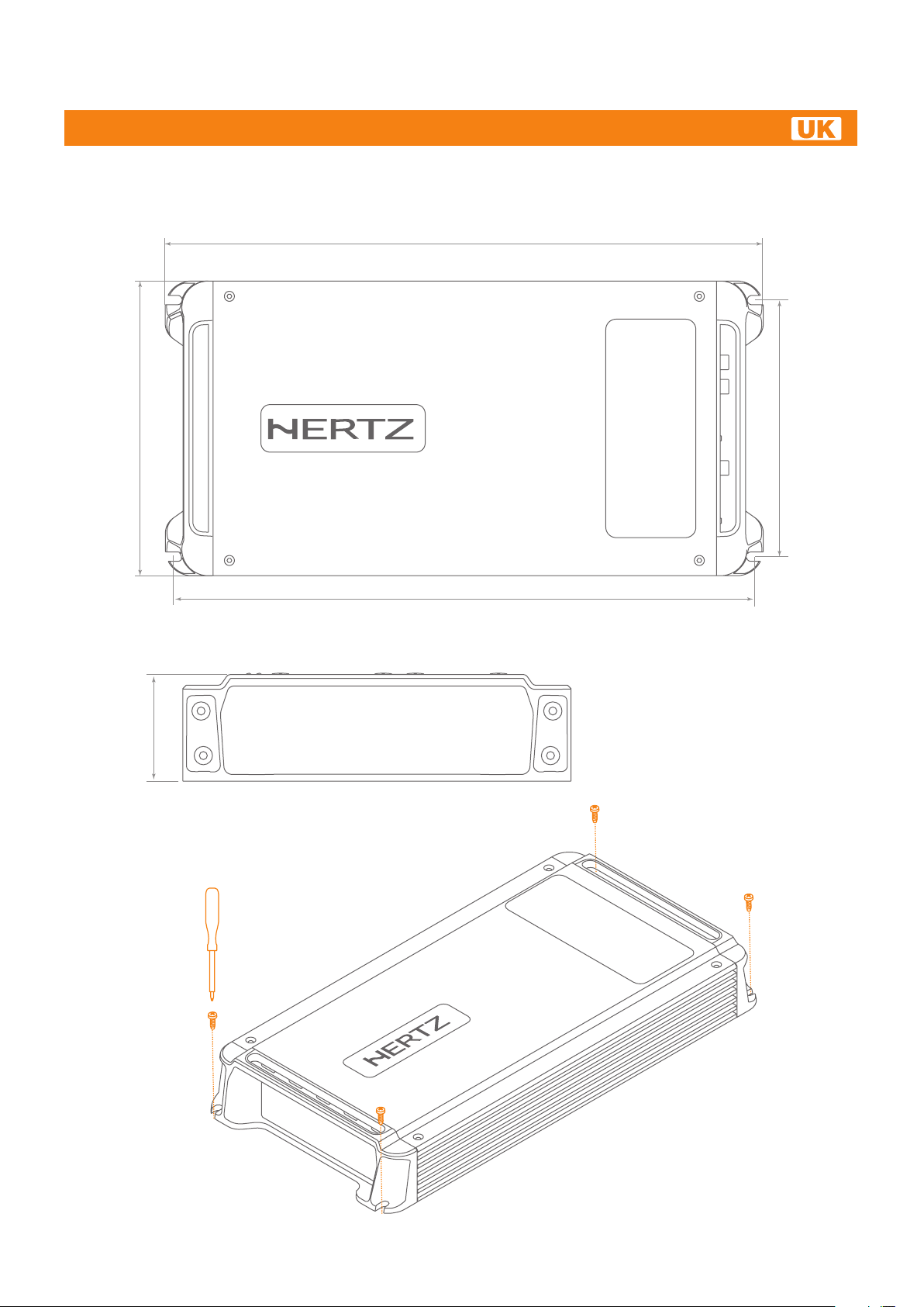
INSTALLATION AND SIZE
Advanced Web Manual
344 mm / 13.54”
171 mm / 6.73”
46,7 mm / 1.83”
150 mm / 5.90”
330 mm / 12.99”
6
Page 7
HDP 5
Advanced Web Manual
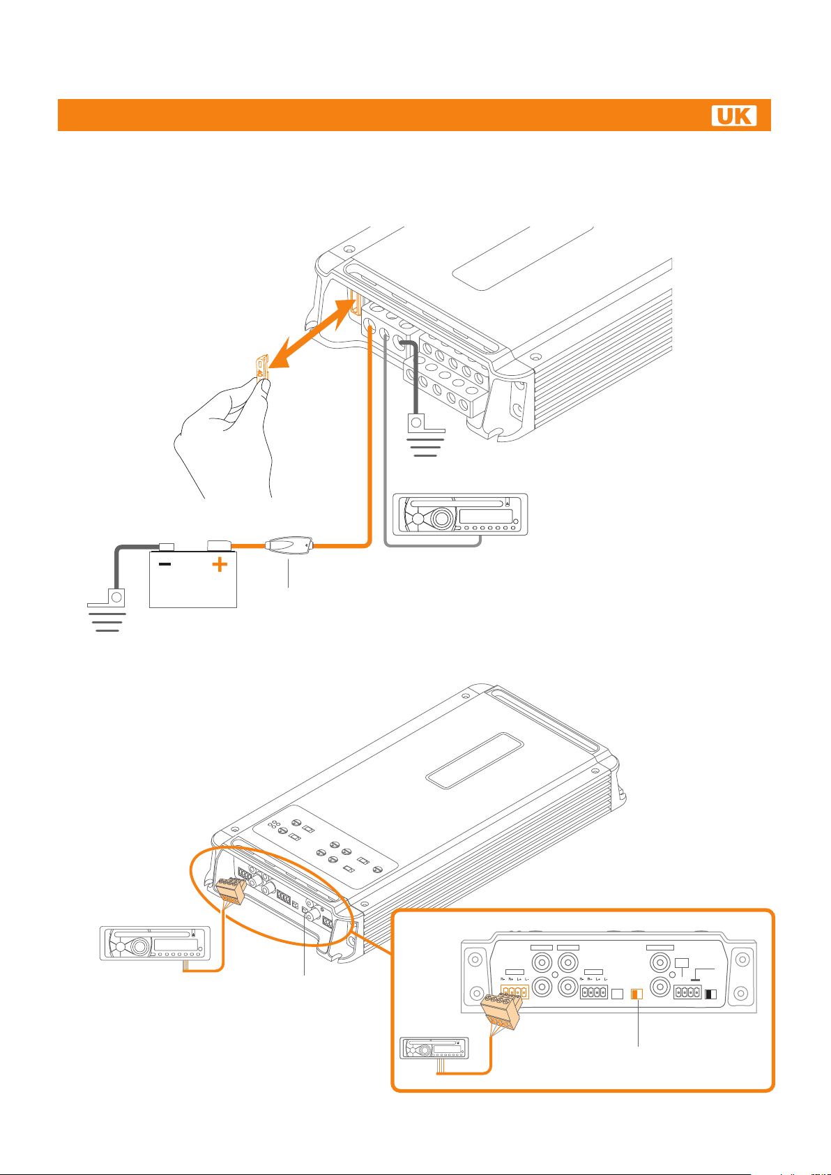
BATTERY / REMOTE CONNECTION AND HOW TO REPLACE THE FUSE
2 x 40 A
BLADE FUSES
GND
+BATTERY
Apply a Fuse
close to positive
pole to protect
+BATTERY wire
AUTO TURN-ON WITH HI-LEVEL INPUTS
ORIGINAL SOURCE
REMOTE OUT
Set the
“HI AUTO TURN-ON”
switch to the
“ON” position
ORIGINAL
SOURCE
7
A PRE - IN B PRE - IN
L
A HI - IN B HI - IN
R
Set the “HI AUTO TURN-ON”
switch to the “ON” position
HDP5
B
INPUT
A BON OFF
HI-IN
AUTO
TURN-ON
SUB PRE - IN
L
R
REMOTE
SUB
VOLUME
HI - IN
CONTROL
SUB
- +
INPUT
A+B SUB
Page 8
HDP 5
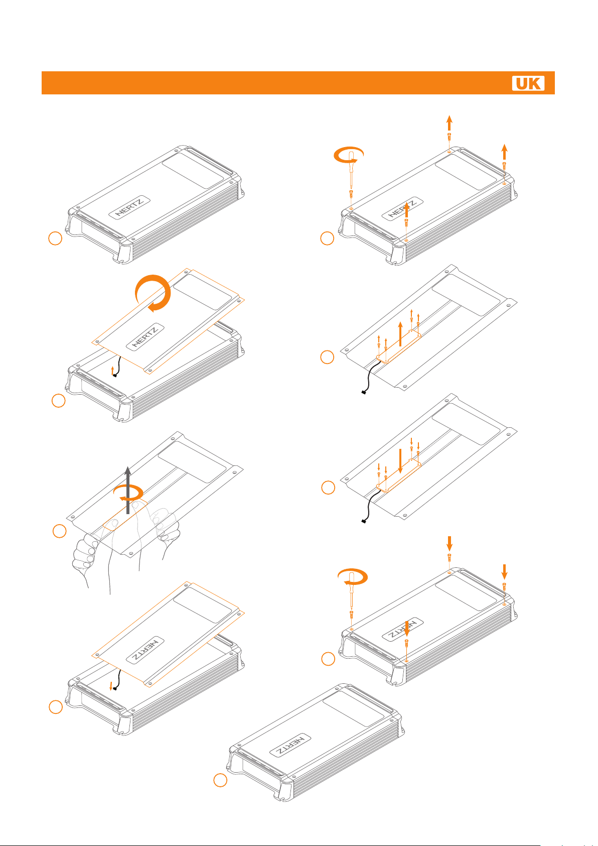
HOW TO ROTATE THE HERTZ LOGO
Advanced Web Manual
1
3
Remove and
Rotate
180°
180°
2
4
6
5
PUSH
8
7
9
8
Page 9
HDP 5
Advanced Web Manual
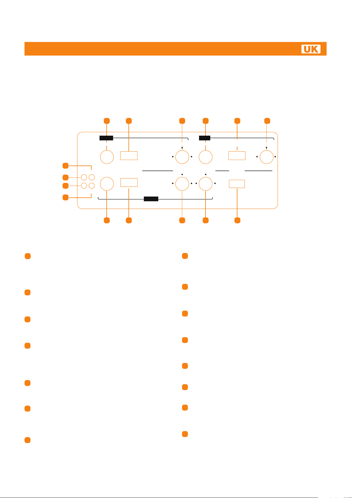
TOP PANEL CONTROLS: SWITCHES AND ADJUSTMENT CONTROLS
1 3
B - ch
LEVELS
34
25
14
ON OVL
12
13
TH SPK
1
LEVELS PASS MODE
34
25
1
15
7
B CH LEVELS (0.3 ÷ 5V): B channels input sensitivity
1
2
PASS MODE
HI FULL
max
HI FULL BAND
max
8
A - ch
adjustment control. Set to 1 position. Use a CD as source,
increase head unit volume until output distorts, then increase
volume by 1 step in order to eliminate distortion. Turn LEVELS
up until sound becomes distorted and then turn LEVELS down
a bit for optimum sound.
2
PASS MODE (HI - FULL): B channels filter switch. Select
FULL to drive full range power outputs. The full frequencies
bandwidth will be output to power output connectors.
Select HI for Hi-pass to drive a MIDRANGE / TWEETER.
HI PASS (80 Hz ÷ 3.3 kHz): B channels HI-PASS crossover
3
point adjustment. Rotating the knob you can select any
frequencies between 80 Hz and 3.3 kHz. The frequencies
below crossover point will be attenuated at 12dB/Oct.
SUB LEVEL (0.3 ÷ 5V): SUB channel input sensitivity
4
adjustment control Set to 1 position. Use a CD as source,
increase head unit volume until output distorts, then increase
volume by 1 step in order to eliminate distortion. Turn LEVELS
up until sound becomes distorted and then turn LEVELS down
a bit for optimum sound.
REMOTE VOLUME CONTROL (ON - OFF): Activate ON or
5
deactivate OFF external remote volume control for SUB channel.
Connect external adjustment control to front panel proper
connectors.
6
LO PASS (40 Hz ÷ 150 Hz): LO-PASS crossover point
adjustment of A channels band-pass filter. Rotating the knob
you can select any frequencies between 40 Hz and 150 Hz.
The frequencies above the crossover point will be attenuated at
24dB/Oct.
7
A CH LEVELS (0.3 ÷ 5V): A channels input sensitivity
adjustment control. Set to 1 position. Use a CD as source,
increase head unit volume until output distorts, then increase
volume by 1 step in order to eliminate distortion. Turn LEVELS
up until sound becomes distorted and then turn LEVELS down
a bit for optimum sound.
4
HI PASS
160800
80 3.3k
HI PASS
70 120
40 150
SUB
LEVEL
34
25
max
1
LO PASS
160 800
80 3.3k
9 10 11
PASS MODE (HI - FULL - BAND): A channels filter switch.
8
Select FULL to drive full range power outputs.
The full frequency bandwidth will be output to power output
connectors. Select HI for Hi-pass to drive a WOOFER.
Select BAND for bandpass to drive a WOOFER or a MIDRANGE.
9
HI PASS (40 Hz ÷ 150 Hz): A channels HI-PASS crossover
point adjustment. Rotating the knob you can select any
frequencies between 40 Hz and 150 Hz. The frequencies below
the crossover point will be attenuated at 12dB/Oct.
LO PASS (80 Hz ÷ 3.3 kHz): A channels LO-PASS crossover
10
point adjustment. Rotating the knob you can select any
frequencies between 80 Hz and 3.3 kHz. The frequencies above
the crossover point will be attenuated at 12dB/Oct.
MODE (3CH - 5CH): Switch for 3 channel or 5 channel
11
amplifier mode. Select 5CH for A + B + SUB channel system
(example: Front - Rear - Sub). Select 3CH for A (Dual Mono)
+ SUB system.
ON: Power LED. It lights up when you turn on the amplifier. If
12
all LEDs (12) (13) (14) (15) turn on at the same time, the amplifier
will shut down and you will have to contact a service centre.
TH: Thermal status LED. It lights up when thermal protection
13
is active, above 85°C. The amplifier shuts down until the chassis
temperature goes below 75°C.
14
OVL: Overload status LED. It lights up when overload occurs
on the power output terminals. The amplifier goes in muting for 3
seconds and this LED starts flashing until you turn off the amplifier.
REMOVE THE CAUSE OF OVERLOAD.
15
SPK: Speaker status LED. It lights up when a speaker touches
car body. The amplifier goes in muting for 3 seconds and this
LED starts flashing until you turn off the amplifier.
REMOVE THE CONTACT BETWEEN SPEAKER WIRE
AND CAR BODY.
5 6
REMOTE VOLUME
CONTROL
OFF ON
MODE
5CH 3CH
HDP5
LO PASS
70 120
40 150
9
Page 10
HDP 5
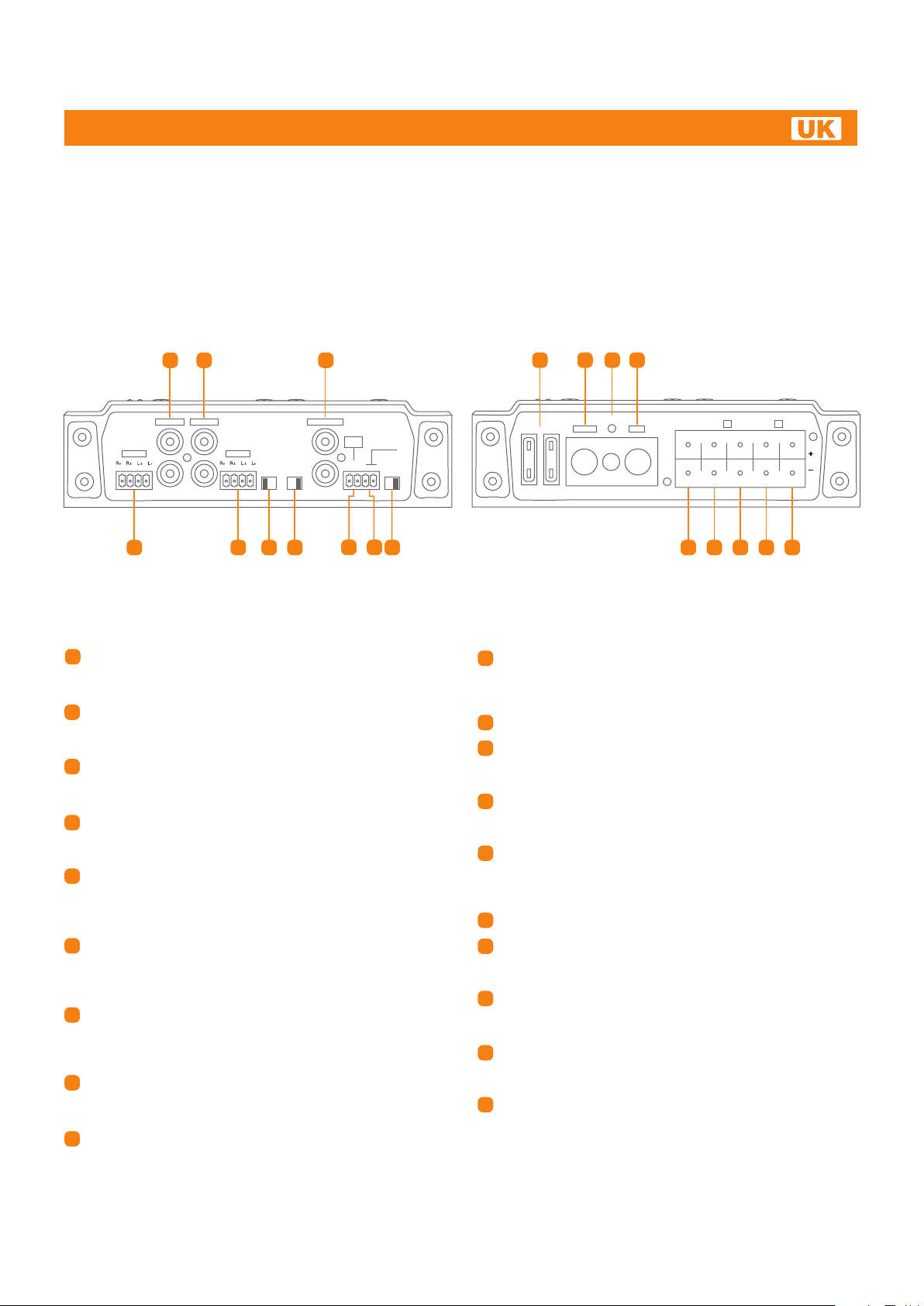
FRONT AND REAR PANELS
1 2 3
Advanced Web Manual
1211
13 14
A PRE - IN B PRE - IN
L
A HI - IN B HI - IN
R
4
1
A PRE-IN: Left and Right pre-amplified inputs to drive
5
HDP5
INPUT
A B ON OFF
B
TURN-ON
6 7
HI-IN
AUTO
SUB PRE - IN
L
R
REMOTE
SUB
VOLUME
HI - IN
CONTROL
SUB
- +
INPUT
A+B SUB
8 9
10 15 16 17 19
A channels. Connect to pre-amplified source output.
Signal can be 0.3 to 5V RMS.
B PRE-IN: Left and Right pre-amplified inputs to drive B
2
channels. Connect to pre-amplified source output.
Signal can be 0.3 to 5V RMS (input active on 5CH mode only).
3
SUB PRE-IN: Pre-amplified L+R (mix) inputs for drive SUB
channel. Connect to pre-amplified source output.
Signal can be 0.3 to 5V RMS.
A HI - IN: Hi-Level signals Left and Right inputs for A channels.
4
If the head unit does not feature a pre-amplified output, connect
here its speaker wire to drive A Left and Right channels.
5
B HI - IN: Hi-Level signals Left and Right inputs for B channels.
If the head unit does not feature a pre-amplified output, connect
here its speaker wire to drive B Left and Right channels (input
active on 5CH mode only).
6
B INPUT (A - B): Select A to drive B channels with A input
signals. With this setup, do not connect B input. If the source
features a REAR output, select B and connect its signals to B
input (B PRE-IN or B HI-IN).
HI - IN AUTO TURN-ON (ON - OFF): Select ON to turn on the
7
amplifier through the speaker power cable, if the source does
not feature a 12V DC REMOTE OUT. Select OFF if REMOTE
OUT from source is available.
8
SUB HI - IN: SUB channel Hi-Level signal inputs. If the head
unit does not feature a pre-amplified output, connect here its
speaker wire to drive SUB channel.
9
REMOTE VOLUME CONTROL: Input for REMOTE SUB
VOLUME CONTROL. Connect here the adjustment control
the amplifier features (optional).
HDP5
FUSE 2 x 40A
+ BATT
REM
GND
SUB
B A
L R
L ( 3 Ch L ) L ( 3 Ch R )
( 3 Ch L )
L R
( 3 Ch R )
18
SUB INPUT (A+B SUB): Select A+B to drive SUB channel with
10
A signals and B signals. With this setup, do not connect SUB
input. If the source features a SUB output, select SUB and
connect its signals to SUB input.
11
PROTECTION FUSE: 2 x 40A.
12
POWER (+ BATT): Terminal block for the amplifier 11 ÷ 15 V
DC power supply positive pole connection. Insert here the
battery positive cable. The plug accepts cables up to 2 A.W.G.
13
REMOTE IN: REMOTE IN terminal for the remote cable
coming from the device which turns on the amplifier.
Voltage must be between 7 and 16V DC.
14
POWER (GND): Terminal block for the amplifier power
supply negative pole connection. Insert here the battery
negative cable or wire connected to the vehicle chassis.
The plug accepts cables up to 2 A.W.G.
15
SUB Speaker OUT: Subwoofer + and - power terminal.
16
BL Speaker OUT: B channel Left speaker + and - power
terminal. For 3CH mode, connect the Left speaker negative
terminal to BL- terminal.
17
BR Speaker OUT: B channel Right speaker + and - power
terminal. For 3CH mode, connect the Left speaker positive
terminal to BR+ terminal.
AL Speaker OUT: A channel Left speaker + and - power
18
terminal. For 3CH mode, connect the Right speaker negative
terminal to AL - terminal.
AR Speaker OUT: A channel Right speaker + and - power
19
terminal. For 3CH mode, connect the Right speaker positive
terminal to AR + terminal.
10
Page 11
lin
HDP 5
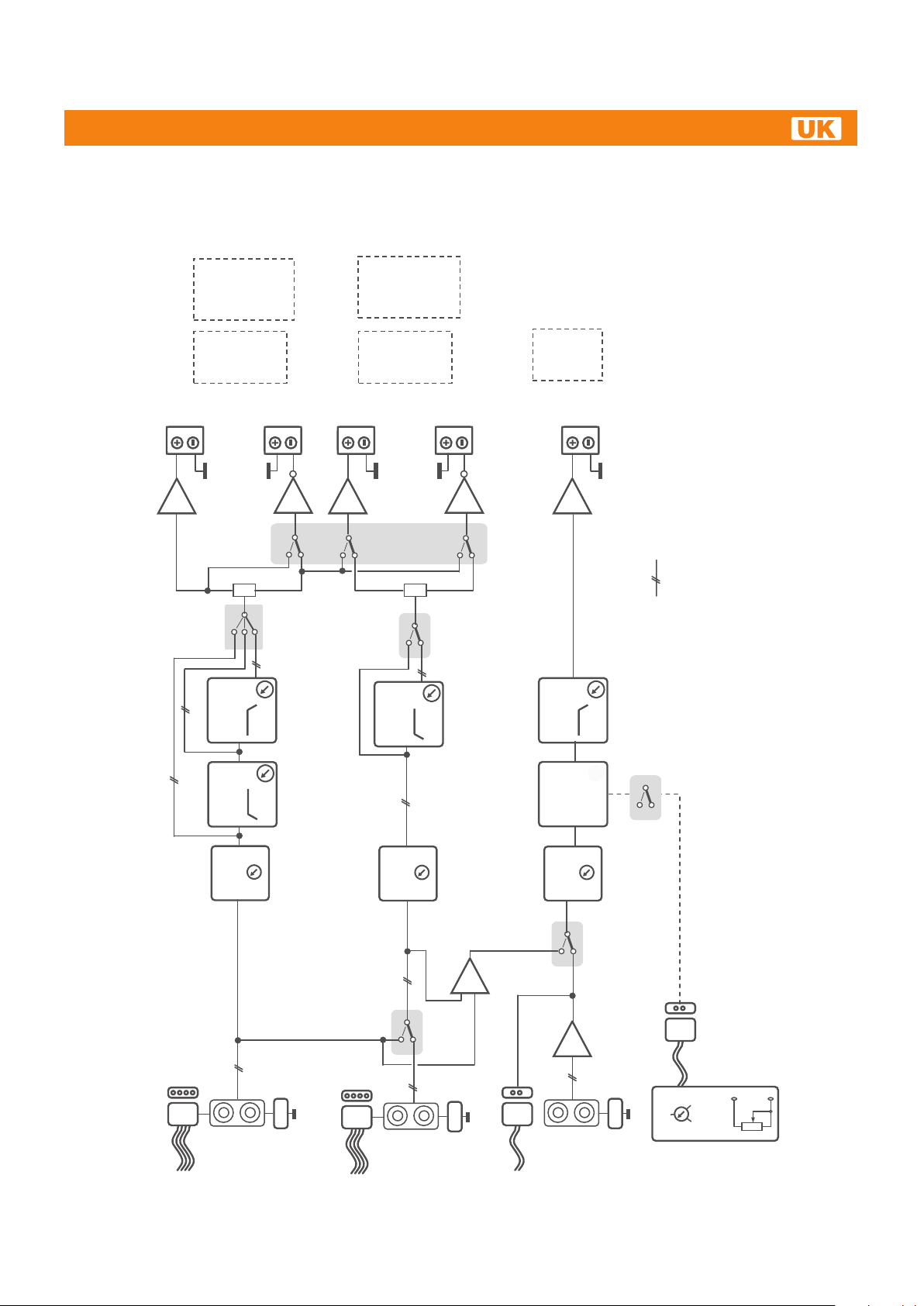
BLOCK DIAGRAM
MODE: 5 ch MODE: 3 ch
Advanced Web Manual
OUT B:
(LEFT CH)
Full
Lo-pass
Hi-pass
+BR / -BL
MONO
OUT A:
(RIGHT CH)
Full
Lo-pass
Hi-pass
+AR / -AL
MONO
(bridge)
OUT B:
Full
OUT A:
Full
Lo-pass
Hi-pass
MODE: 5 ch MODE: 3 ch
Hi-pass
(bridge)
OUT
SUB:
Lo-pass
MONO
AMP
A
B = Hi-pass
C = Band-pass
B RIGHT
R
AMP
A
B
R
S2
B
A
HI-PASS
80 - 3.3k Hz
A RIGHT
R
AMP
R
S4
LO-PASS
80 - 3.3k Hz
HI-PASS
40 - 150 Hz
S5
CBA
12dB/Oct.
12dB/Oct.
B
L
A PASS MODE
A LEFT
L
= Full
P4 P5
L
B PASS MODE
12dB/Oct.
B
= Full
P6
B LEFT
L
AMP
B = Hi-pass
SUB
SUB
AMP
MODE
= 5 ch
A
B = 3 ch
STEREO SIGNALS
LO-PASS
40-150 Hz
REMOTE
SUB VOL
CONTROL
P7
24dB/Oct.
S6
-50 / 0 / +6 dB
= ON
B = OFF
REMOTE CONTROL
A
B
A LEVEL
5V – 300mV
P1
L
A
R
HI-IN
(1.4-24V)
L
R
RCA prot
A
PRE-IN
L
B
R
HI-IN
(1.4-24V)
B LEVEL
S1
L
5V – 300mV
B
A
B
PRE-IN
P3
5V – 300mV
HI-IN
(1.4-24V)
SUB LEVEL
S3
B
A
= SUB INPUT
SUB INPUT
B = A+B INPUT
MIX
L
R
-
MIN - MAX
SUB Vol.
CONTROL
SUB
PRE-IN
RCA prot
0 dB
REMOTE
P2
MIX
B INPUT
A = B INPUT
B = A INPUT
R
RCA prot
SUB
11
Page 12
HDP 5
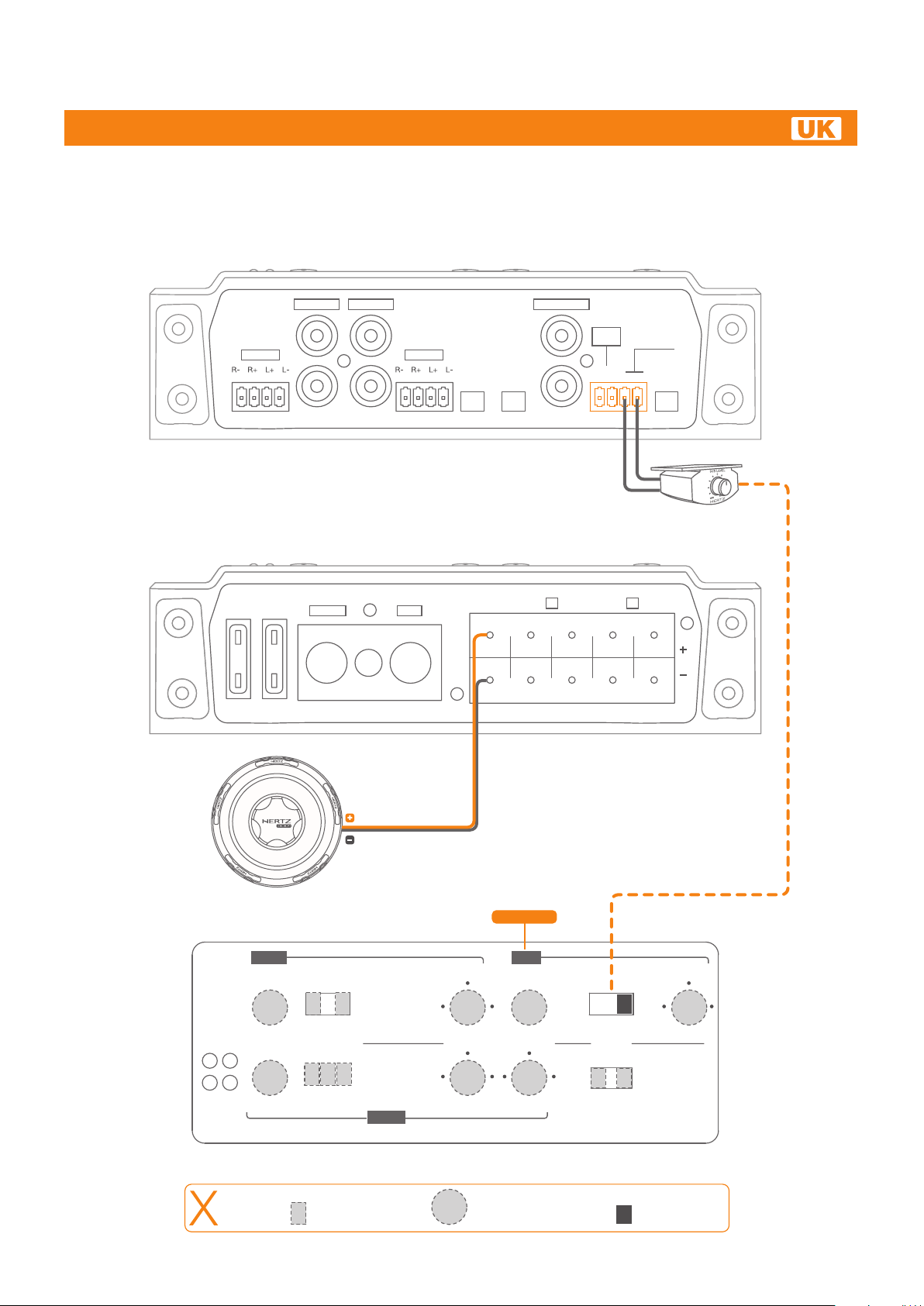
HOW TO USE REMOTE VOLUME CONTROL
Advanced Web Manual
A PRE - IN B PRE - IN
L
A HI - IN B HI - IN
R
HDP5
FUSE 2 x 40A
+ BATT
REM
GND
HDP5
B
TURN-ON
INPUT
A BON OFF
SUB
SUB PRE - IN
HI-IN
AUTO
L
R
SUB
HI - IN
- +
HRC
REMOTE VOLUME CONTROL
B A
L R ( 3 Ch L ) L R ( 3 Ch R )
L ( 3 Ch L ) L ( 3 Ch R )
REMOTE
VOLUME
CONTROL
SUB
INPUT
A+B SUB
OPTIONAL
Subwoofer
25
ON OVL
25
TH SPK
N.A.
B - ch
34
max
1
34
max
1
PASS MODE
HI FULL
HI FULL BAND
LEVELS
LEVELS PASS MODE
Selected function
A - ch
SUBWOOFER
HI PASS
160 800
80 3.3k
HI PASS
70 120
40 150
SUB
LEVEL LO PASS
34
25
1
LO PASS
160 800
80 3.3k
REMOTE VOLUME
CONTROL
OFF ON
max
5CH 3CH
MODE
HDP5
Adjustment controls System Start-up
12
70 120
40 150
Page 13
HDP 5
FRONT + REAR + SUB WITH REMOTE VOLUME CONTROL
Advanced Web Manual
A PRE - IN B PRE - IN
L
A HI - IN B HI - IN
R
R
L
HDP5
FUSE 2 x 40A
+ BATT
REM
GND
HDP5
INPUT
SOURCE
HI-IN
AUTO
B
TURN-ON
A BON OFF
SUB
SUB PRE - IN
L
R
SUB
HI - IN
- +
REMOTE
VOLUME
CONTROL
SUB
INPUT
A+B SUB
OPTIONAL
HRC
REMOTE VOLUME CONTROL
B A
L R ( 3 Ch L ) L R ( 3 Ch R )
L
( 3 Ch L )
L
( 3 Ch R )
SUBWOOFER
25
ON OVL
25
TH SPK
N.A.
B - ch
34
max
1
34
max
1
PASS MODE
HI FULL
HI FULL BAND
LEVELS
LEVELS PASS MODE
Selected function
A - ch
FRONT
L
REAR
R
HI PASS
160800
80 3.3k
HI PASS
70 120
40 150
Adjustment controls
FRONT
SUBWOOFERREAR
SUB
LEVEL LO PASS
34
25
1
LO PASS
160 800
80 3.3k
REMOTE VOLUME
CONTROL
OFF ON
max
5CH 3CH
MODE
HDP5
System Start-up
R
L
70 120
40 150
13
Page 14
HDP 5
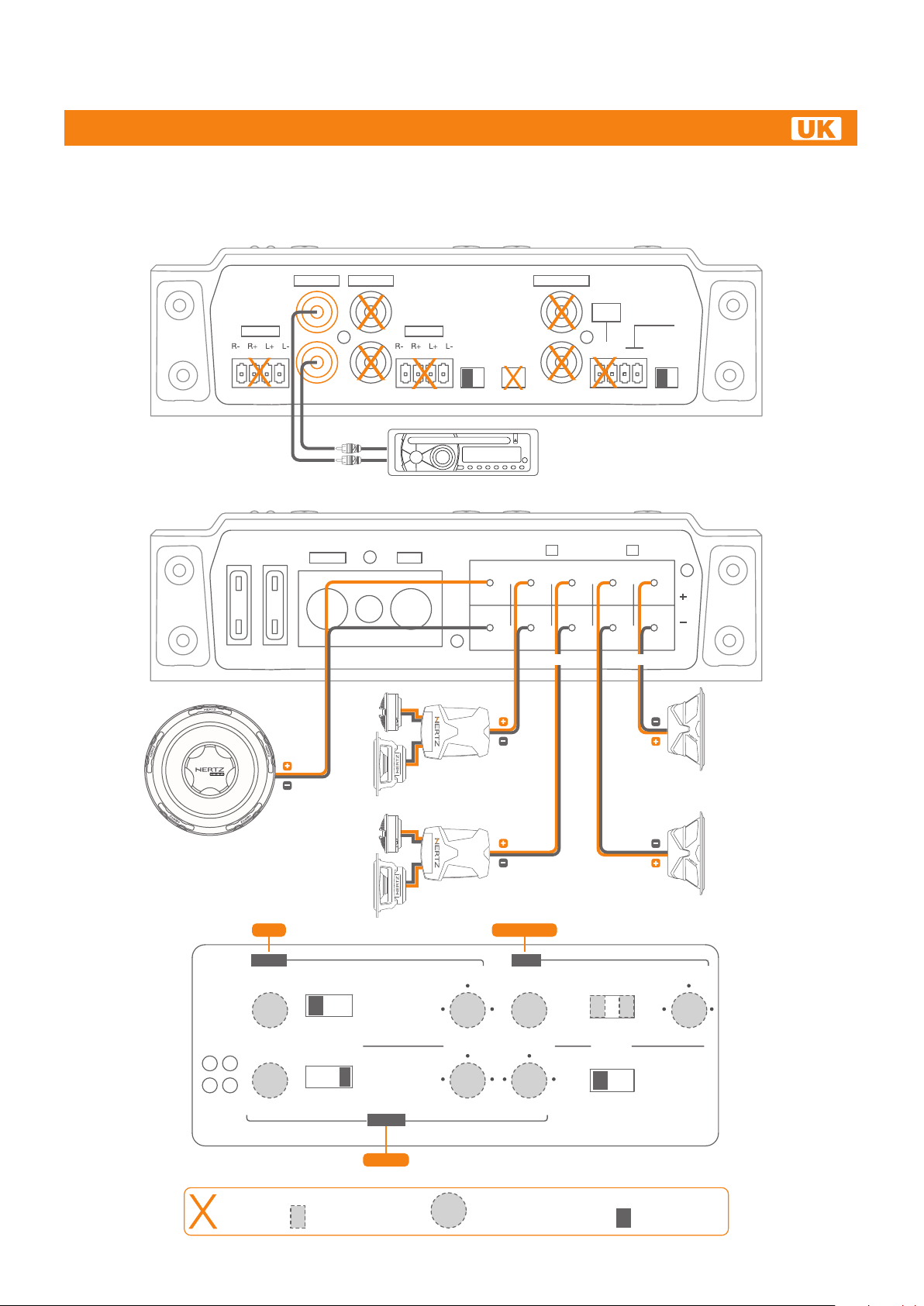
WOOFER AND MID/HI AND SUB
Advanced Web Manual
A PRE - IN B PRE - IN
L
A HI - IN B HI - IN
R
R
L
REM
HDP5
FUSE 2 x 40A
FRONT
+ BATT
L
GND
HDP5
INPUT
SOURCE
HI-IN
AUTO
B
TURN-ON
A BON OFF
SUB
SUB PRE - IN
L
R
B A
L R ( 3 Ch L ) L R ( 3 Ch R )
L ( 3 Ch L ) L ( 3 Ch R )
SUB
HI - IN
- +
REMOTE
VOLUME
CONTROL
SUB
INPUT
A+B SUB
R
SUBWOOFER
ON OVL
TH SPK
N.A.
B - ch
34
max
1
34
max
1
PASS MODE
HI FULL
HI FULL BAND
LEVELS
25
LEVELS PASS MODE
25
Selected function
R
A - ch
WOOFER
MID/HI
HI PASS
160 800
80 3.3k
HI PASS
70 120
40 150
Adjustment controls
WOOFER
SUBWOOFERMID/HI
SUB
LEVEL LO PASS
34
25
1
LO PASS
160800
80 3.3k
REMOTE VOLUME
CONTROL
OFF ON
max
5CH 3CH
MODE
HDP5
System Start-up
L
70 120
40 150
14
Page 15

HDP 5
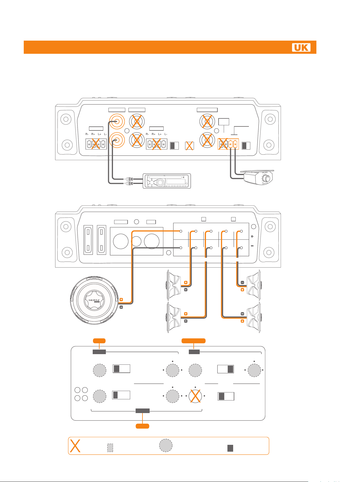
PRE-IN FRONT AND PRE-IN SUB
Advanced Web Manual
A PRE - IN B PRE - IN
L
A HI - IN B HI - IN
R
R
L
REM
HDP5
FUSE 2 x 40A
FRONT REAR/SUB
+ BATT
GND
HDP5
INPUT
SOURCE
HI-IN
AUTO
B
TURN-ON
A BON OFF
SUB
SUB PRE - IN
L
SUB
HI - IN
- +
R
R
L
B A
( 3 Ch L )
L R
L ( 3 Ch L ) L ( 3 Ch R )
L R
REMOTE
VOLUME
CONTROL
SUB
INPUT
A+B SUB
( 3 Ch R )
SUBWOOFER
ON OVL
TH SPK
B - ch
34
max
1
34
max
1
PASS MODE
HI FULL
HI FULL BAND
LEVELS
25
LEVELS PASS MODE
25
A - ch
WOOFER
L
FRONT
TWEETER
R
HI PASS
160 800
80 3.3k
HI PASS
70 120
40 150
SUBWOOFERTWEETER
SUB
LEVEL LO PASS
34
25
1
LO PASS
160800
80 3.3k
REMOTE VOLUME
CONTROL
OFF ON
max
5CH 3CH
MODE
HDP5
R
FRONT
WOOFER
L
70 120
40 150
N.A.
Selected function
Adjustment controls
15
System Start-up
Page 16

HDP 5
PRE-IN FRONT, PRE-IN REAR AND PRE-IN SUB
Advanced Web Manual
A PRE - IN B PRE - IN
L
A HI - IN B HI - IN
R
R
L
R
L
REM
HDP5
FUSE 2 x 40A
FRONT SUB
+ BATT
GND
HDP5
INPUT
A BON OFF
REAR
SOURCE
SUB PRE - IN
L
HI-IN
AUTO
B
TURN-ON
R
SUB
HI - IN
- +
REMOTE
VOLUME
CONTROL
SUB
INPUT
A+B SUB
R
L
SUB
B A
L R ( 3 Ch L ) L R ( 3 Ch R )
L ( 3 Ch L ) L ( 3 Ch R )
SUBWOOFER
ON OVL
TH SPK
B - ch
34
max
1
34
max
1
PASS MODE
HI FULL
HI FULL BAND
LEVELS
25
LEVELS PASS MODE
25
A - ch
FRONT
L
R
HI PASS
160 800
80 3.3k
HI PASS
70 120
40 150
REAR
SUBWOOFERREAR
SUB
LEVEL LO PASS
34
25
1
LO PASS
160800
80 3.3k
REMOTE VOLUME
CONTROL
OFF ON
max
5CH 3CH
MODE
R
FRONT
L
70 120
40 150
HDP5
N.A.
Selected function
Adjustment controls
16
System Start-up
Page 17

HDP 5
HI-IN FRONT INPUTS WITH FRONT, REAR AND SUB OUTPUTS
Advanced Web Manual
A PRE - IN B PRE - IN
L
A HI - IN B HI - IN
R
L
SPEAKERS WIRE
HDP5
FUSE 2 x 40A
+ BATT
R
REM
GND
HDP5
B
INPUT
A BON OFF
SOURCE
SUB
SUB PRE - IN
L
HI-IN
AUTO
TURN-ON
R
B A
L R
L ( 3 Ch L ) L ( 3 Ch R )
( 3 Ch L )
SUB
HI - IN
- +
L R
REMOTE
VOLUME
CONTROL
SUB
INPUT
A+B SUB
( 3 Ch R )
SUBWOOFER
ON OVL
TH SPK
B - ch
34
max
1
34
max
1
PASS MODE
HI FULL
HI FULL BAND
LEVELS
25
LEVELS PASS MODE
25
A - ch
FRONT
FRONT
L
R
HI PASS
160800
80 3.3k
HI PASS
70 120
40 150
REAR
SUBWOOFERREAR
SUB
LEVEL LO PASS
34
25
1
LO PASS
160800
80 3.3k
REMOTE VOLUME
CONTROL
OFF ON
max
5CH 3CH
MODE
HDP5
R
FRONT
L
70 120
40 150
N.A.
Selected function
Adjustment controls
17
System Start-up
Page 18

HDP 5
HI-IN FRONT AND REAR
Advanced Web Manual
A PRE - IN B PRE - IN
L
A HI - IN B HI - IN
R
L
SPEAKERS WIRE
FRONT
HDP5
FUSE 2 x 40A
+ BATT
R
REM
HDP5
INPUT
RL
SOURCE
GND
HI-IN
AUTO
B
TURN-ON
A BON OFF
SPEAKERS WIRE
SUB
SUB PRE - IN
L
R
SUB
HI - IN
- +
REMOTE
VOLUME
CONTROL
SUB
INPUT
A+B SUB
REAR
B A
L R ( 3 Ch L ) L R ( 3 Ch R )
L ( 3 Ch L ) L ( 3 Ch R )
SUBWOOFER
ON OVL
TH SPK
N.A.
B - ch
34
max
1
34
max
1
PASS MODE
HI FULL
HI FULL BAND
LEVELS
25
LEVELS PASS MODE
25
Selected function
A - ch
FRONT
L
REAR
R
HI PASS
160 800
80 3.3k
HI PASS
70 120
40 150
Adjustment controls
FRONT
SUBWOOFERREAR
SUB
LEVEL LO PASS
34
25
1
LO PASS
160800
80 3.3k
REMOTE VOLUME
CONTROL
OFF ON
max
5CH 3CH
MODE
HDP5
System Start-up
R
L
70 120
40 150
18
Page 19

HDP 5
PRE-IN FRONT AND HI-IN REAR
Advanced Web Manual
A PRE - IN B PRE - IN
L
A HI - IN B HI - IN
R
R
L
REM
HDP5
FUSE 2 x 40A
SPEAKERS WIRE
FRONT
+ BATT
GND
HDP5
INPUT
A BON OFF
R
SOURCE
HI-IN
AUTO
B
TURN-ON
SPEAKERS WIRE
L
SUB
L R ( 3 Ch L ) L R ( 3 Ch R )
L
SUB PRE - IN
L
R
REAR
B A
( 3 Ch L )
SUB
HI - IN
- +
L
( 3 Ch R )
REMOTE
VOLUME
CONTROL
SUB
INPUT
A+B SUB
SUBWOOFER
ON OVL
TH SPK
B - ch
34
max
1
34
max
1
PASS MODE
HI FULL
HI FULL BAND
LEVELS
25
LEVELS PASS MODE
25
A - ch
FRONT
L
R
HI PASS
160800
80 3.3k
HI PASS
70 120
40 150
REAR
SUBWOOFERREAR
SUB
LEVEL LO PASS
34
25
1
LO PASS
160 800
80 3.3k
REMOTE VOLUME
CONTROL
OFF ON
max
5CH 3CH
MODE
R
FRONT
L
70 120
40 150
HDP5
N.A.
Selected function
Adjustment controls
19
System Start-up
Page 20

HDP 5
3CH MODE: FRONT AND SUB
Advanced Web Manual
A PRE - IN B PRE - IN
L
A HI - IN B HI - IN
R
R
L
HDP5
FUSE 2 x 40A
+ BATT
REM
GND
HDP5
B
INPUT
A BON OFF
SOURCE
SUB
SUB PRE - IN
L
HI-IN
AUTO
TURN-ON
R
B A
L R ( 3 Ch L ) L R ( 3 Ch R )
L
( 3 Ch L )
SUB
HI - IN
- +
L
( 3 Ch R )
REMOTE
VOLUME
CONTROL
SUB
INPUT
A+B SUB
SUBWOOFER
ON OVL
TH SPK
B - ch
34
max
1
34
max
1
PASS MODE
HI FULL
HI FULL BAND
LEVELS
25
LEVELS PASS MODE
25
A - ch
FRONT
HI PASS
160 800
80 3.3k
HI PASS
70 120
40 150
FRONT
SUBWOOFER
SUB
LEVEL LO PASS
34
25
1
LO PASS
160800
80 3.3k
REMOTE VOLUME
CONTROL
OFF ON
max
5CH 3CH
MODE
HDP5
RL
70 120
40 150
N.A.
Selected function
Adjustment controls
20
System Start-up
Page 21

HDP 5
Advanced Web Manual
CABLES
Connection cables
For maximum performance, always use new, good quality cables; their outer jacket must not be spoiled, and the copper must not
show oxidation. For proper operation, always consider the length of the connection, the load and the current it has to handle.
Connection products are the most flexible and complete; they are designed and built in order to get the best out of every installation,
especially when used with Hertz amplifiers.
Speaker cable recommendations
The table refers to continuous power into 4 Ω load. If load
decreases, cable size will have to increase proportionally.
Potenza applicata
Diametro del cavo
Lunghezza del collegamento
Power and Ground cable recommendations
If you don’t know your system current consumption, find it using the mathematical formula below and find this same value on the left
hand column of the table. Then calculate the length of your connection and find this same value on the bottom column of the table. At
the point where these two values cross is the minimum section in gauge (A.W.G.) which Connection recommends for building a high
performance, reliable system.
How to calculate your system
current consumption
I =
TP x 2
Vbatt
I = Current consumption of your system in
ampere (A);
TP = Total power (RMS) of channels of all
amplifiers in your system;
Vbatt = Usually value is 12 V, the nominal
automotive electrical system voltage.
Example:
• Your total system power (RMS) of all channels
in all amplifiers is a combined 650 W.
• Your amplifier average is 50% efficiency, as most
amplifiers today.
• Your electrical system is 12 V.
650 x 2
I = = 108,3 A Current consumption
12
*Current Draw I (A)
21
Cable Length (m)
Page 22

HDP 5
TECHNICAL SPECIFICATIONS
Power Supply
Power supply voltage: 11÷15 VDC
Idling current: 3 A
Idling current when off: 0.04 mA
Consumption @ 2Ω, 14.4 VDC
(Max Musical Power): 50 A
Amplifier stage
Distortion - THD (100 Hz @ 4Ω): 0.08 %
Bandwidth A & B Ch (-3 dB): 5 ÷ 50k Hz
Bandwidth C Ch (-3 dB): 5 ÷ 150 Hz
S/N Ratio A & B Ch (A weighted @ 1 V): 100 dB
S/N Ratio C Ch (A weighted @ 1 V): 106 dB
Damping factor A & B Ch (100 Hz @ 4Ω): 50
Damping factor C Ch (100 Hz @ 4Ω): 100
Pre-In sensitivity: 0.3 ÷ 5 V RMS
Pre-In impedance: 15 kΩ
Speaker-In sensitivity: 1.4 ÷ 24 V
Speaker-In impedance: 470 Ω
Load impedance:
5 Ch 4 x 2Ω + 1 x 2Ω
3 Ch 2 x 4Ω + 1 x 2Ω
Advanced Web Manual
CEA 2006-A RATINGS
CEA 2006-A RATINGS
RMS Power (4 Ω, ≤ 1 % THD+N, 14.4 V): 60W x 4Ch + 310W x 1Ch
S/N Ratio (ref. 1 W output):
60 W Channel: 80 dBA
310 W Channel: 84 dBA
OUTPUT POWER (RMS) @ 14.4 VDC, THD 1%:
5 Ch 70W x 4 + 380W x 1 (4Ω)
5 Ch 100W x 4 + 550W x 1 (2Ω)
3 Ch 200W x 2 (4Ω) + 380W x 1 (4Ω)
3 Ch 200W x 2 (4Ω) + 550W x 1 (2Ω)
Inputs/Outputs/Filters
Inputs: Pre IN / Speakers IN
A Ch filters: Full/Hi-Pass/Band-Pass
40 ÷ 150 Hz (HI) 80 ÷ 3.3k Hz (LO) @ 12 dB/Oct.
B Ch filters: Full/Hi-Pass 80 ÷ 3.3k Hz @ 12 dB/Oct.
C Ch filters: Lo-Pass 40 ÷ 150 Hz @ 24 dB/Oct.
Remote SUB volume: (-50 ÷ 6) dB
Other functions
Remote In: 6 ÷ 15 VDC - 1 mA
TM
ART
: Automatic Remote Turn-On/Off with Speaker-In
Fuse: 2 x 40 A
Size
WxHxD (mm / inches) 171x 344 x 46.70 / 6.73” x 13.54” x 1.83”
Weight (kg/lb) 3,09 / 6,81
22
Page 23

23
Page 24

HDP 5
Advanced Web Manual
INDICE
Introduzione 25
Contenuto dell’imballo 25
Safe Sound 26
Precauzioni generali 27
Installazioni e dimensioni 28
Connessione alimentazione / Remote e sostituzione fusibile 29
Auto Turn-On con ingressi Hi-Level 29
Come ruotare il logo Hertz 30
Pannello controlli: switch e regolazioni 31
Pannelli Front e Rear 32
Schema a blocchi 33
Esempi
Come usare il Remote Volume Control 34
Front e Rear e Sub con il Remote Volume Control 35
Woofer e MID/HI e SUB 36
PRE-IN Front e PRE-IN Sub 37
PRE-IN Front, PRE-IN Rear e PRE-IN Sub 38
Ingressi HI-IN Front con uscite Front, Rear e Sub 39
HI-IN Front e Rear 40
PRE-IN Front e HI-IN Rear 41
3 CH MODE: FRONT e SUB 42
Cavi 43
Specifiche tecniche 44
24
Page 25

HDP 5
Advanced Web Manual
INTRODUZIONE
Grazie per avere acquistato un prodotto Hertz, progettato secondo i migliori standard qualitativi.
L’amplificatore audio HDP in vostro possesso è un prodotto innovativo dalle dimensioni ridottissime in grado di fornire elevata potenza
e qualità musicale. Senza dubbio con questo amplificatore otterrete il massimo della soddisfazione occupando uno spazio piccolissimo
nella vostra automobile.
Prima di installarlo, oltre ad aver letto la guida rapida (QSG), la consultazione di questo manuale d’uso, disponibile sul sito Hertz, vi
permetterà di ottenere il massimo delle prestazioni dal vostro amplificatore.
CONTENUTO DELL’IMBALLO
Al’interno della confezione oltre al vostro amplificatore HDP 5 troverete:
• Quick Start Guide ...............................................................................................................................................................
• Il libretto di garanzia ...........................................................................................................................................................
• Fusibile a lama da 40 A ..................................................................................................................................................... x2
• Viti di fissaggio con testa a croce autofilettanti 4,2 x 16 mm.................................................................................................. x4
OPZIONALE
• HRC, controllo remoto volume SUB..........................................................................................................................
40
25
Page 26

HDP 5
Advanced Web Manual
SAFE SOUND
GLI AMPLIFICATORI HERTZ SONO IN GRADO DI CREARE SISTEMI AUDIO AD ALTA POTENZA CHE POSSONO GENERARE
ELEVATISSIME PRESSIONI SONORE INDISTORTE. RICORDATE CHE PROLUNGATE ESPOSIZIONI AD UN LIVELLO ECCESSIVO
DI PRESSIONE ACUSTICA POSSONO PRODURRE DANNI AL VOSTRO UDITO: UTILIZZATE DUNQUE EQUILIBRIO E BUON
SENSO NELL’ASCOLTO.
La sicurezza durante la guida deve restare sempre al primo posto. In ogni situazione il volume d’ascolto deve avere un livello tale da non
coprire i rumori provenienti dall’esterno; dovreste essere in condizione di udire anche quelli del vostro veicolo per affrontare prontamente
situazioni di emergenza.
Per ottenere il massimo delle prestazioni dal vostro nuovo amplificatore vi consigliamo di seguire attentamente le istruzioni del presente
manuale. La realizzazione di un sistema hi-fi car di alto livello richiede una buona conoscenza delle problematiche meccaniche ed
elettriche delle autovetture; qualora riteneste di non possedere gli attrezzi necessari o la conoscenza adeguata, non esitate a contattare
un installatore specializzato. Un’installazione a regola d’arte vi assicurerà prestazioni entusiasmanti e coinvolgenti, senza influire sulla
sicurezza e l’affidabilità della vostra autovettura.
Questo manuale è stato redatto per fornire le indicazioni principali e necessarie all’installazione e all’uso dell’amplificatore. Nonostante
il gran numero di informazioni e suggerimenti, potrebbe non contenere esattamente le modalità di montaggio per la vostra particolare
autovettura. Se, dopo averlo letto, aveste ancora delle domande, non esitate a contattare il vostro rivenditore Hertz.
Per qualsiasi ulteriore informazione potrete contattare l’assistenza Hertz via mail scrivendo direttamente agli indirizzi:
Per l’Italia - supporto.tecnico@elettromedia.it
Per l’estero - support@elettromedia.it
26
Page 27

HDP 5
Advanced Web Manual
PRECAUZIONI GENERALI
• Il simbolo a lato indica che è opportuno prestare attenzione alle indicazioni riportate. La mancata osservanza di tali
istruzioni potrebbe causare lesioni involontarie o danni all’apparecchio.
• Prima di procedere all’installazione assicuratevi di aver letto con cura e capito tutte le istruzioni.
• L'impianto elettrico del veicolo deve avere una tensione di 12V DC con negativo a massa. Verificate che il veicolo abbia
tali caratteristiche per evitare danni sia all'amplificatore che al veicolo stesso.
• Per facilitare l’installazione, prima di tutto programmate la configurazione del vostro nuovo amplificatore e fate passare i
cavi nel modo migliore possibile.
• Indossate sempre occhiali protettivi durante l’utilizzo di attrezzi che possono generare schegge o residui di lavorazione.
• Riponete, quando è possibile, l’amplificatore nell’imballo durante l’installazione per evitare danni accidentali.
• Fissate tutte le strutture supplementari realizzate per installare i vari componenti alla struttura del veicolo in modo solido e affidabile
tramite staffe, viti, dadi e bulloni, per assicurare stabilità e sicurezza in condizioni di marcia.
• Il distaccamento dal fissaggio durante la marcia dell’autovettura può causare grave danno per le persone trasportate e per gli altri veicoli. Fissate
adeguatamente l'amplificatore, facendo la massima attenzione nel caso in cui l'installazione sia all'interno dell'abitacolo. Non realizzate alcun tipo di
installazione all'interno del vano motore.
• Prima dell’installazione, spegnete la sorgente e tutti gli apparati elettronici del sistema audio per evitare qualsiasi possibile danno.
• Assicuratevi che il posizionamento prescelto per i componenti non interferisca con il corretto funzionamento di ogni dispositivo meccanico o elettrico
della vettura.
• Evitate di passare i cavi o installare l’amplificatore in prossimità di centraline elettroniche.
• Prestate estrema attenzione nel praticare fori o tagli sulla lamiera, verificando che sotto o nella zona interessata non vi sia alcun cavo elettrico o
elemento strutturale e vitale per l’autovettura.
• Prima di collegare il cavo di alimentazione all’amplificatore, sconnettete il cavo negativo (-) dalla batteria della vostra auto.
• Assicuratevi di non cortocircuitare il cavo di alimentazione durante l’installazione e il collegamento.
• Il cavo di alimentazione deve essere provvisto di isolamento meccanicamente resistente ed autoestinguente alla fiamma. La sezione del cavo deve
essere dimensionata come quanto suggerito nel presente manuale. Nel posizionamento, evitate di schiacciare il cavo contro parti taglienti o nella
vicinanza di organi meccanici in movimento. Assicuratevi che sia adeguatamente fissato per tutta la sua lunghezza. Bloccate, tramite un serrafilo, il
cavo positivo e negativo immediatamente a ridosso dei rispettivi morsetti d’alimentazione dell'amplificatore.
• Proteggete il cavo conduttore con un anello in gomma se passa in un foro della lamiera o con appositi materiali se scorre vicino a parti che generano calore.
• Per fissare il collegamento di massa (-) in modo corretto usate una vite già presente sulla parte metallica del veicolo; rimuovete ogni residuo di materiale
che impedisca un collegamento perfetto, assicurandovi con un tester che vi sia continuità tra il terminale negativo (-) della batteria e il punto di fissaggio.
Se possibile, collegate tutti i componenti allo stesso punto di massa poiché questa soluzione serve per abbattere la maggior parte dei rumori.
• Fate passare i cavi di segnale lontano dai fili d’alimentazione.
• Non fate passare mai i fili all’esterno del veicolo; non avreste protezione sufficiente contro l’usura o in caso d’incidente.
• Nell'installazione degli altoparlanti e dei cavi che li collegano, accertatevi che non vadano in contatto, anche in modo saltuario, con parti taglienti del
veicolo. In tal caso interverrà la protezione dell'amplificatore.
• Per evitare problemi usate cavi, connettori e accessori di alta qualità scegliendoli nel catalogo Connection.
• A fine installazione, ma prima di connettere il fusibile principale di alimentazione, ricontrollate l’intero cablaggio del sistema e assicuratevi di aver
eseguito tutti i collegamenti in maniera corretta.
• Gli amplificatori di potenza comportano un ulteriore carico sulla batteria e sul suo sistema di ricarica. E’ bene che controlliate le condizioni di alternatore e
batteria per assicurarvi che siano in grado di sopportare l’incremento di assorbimento. I sistemi elettrici standard in buone condizioni dovrebbero reggere
senza problemi, ma Vi consigliamo di utilizzare un condensatore ad altissima capacità e/o una batteria specifica per sistemi audio ad alto livello.
• Applicate un fusibile con relativo portafusibile isolato a non più di 40 cm dal morsetto positivo della batteria e collegate su di esso il cavo di alimentazione
dopo averne collegata l'altra estremità all'amplificatore. Il valore del fusibile deve essere superiore del 50% rispetto a quello posto all'interno
dell'amplificatore. Nel caso il cavo alimenti più amplificatori, il fusibile dovrà avere un valore superiore del 50% rispetto alla somma dei valori di tutti i
fusibili presenti sugli amplificatori.
• La zona di installazione deve avere un'adeguata circolazione d'aria e non deve essere esposta ad umidità, pioggia, detriti provenienti dall'esterno o
dagli organi meccanici del veicolo. Non impedite in alcun modo il raffreddamento delle alette laterali dell’amplificatore.
• Installate l'amplificatore in zone del veicolo ove la temperatura non scenda sotto gli 0°C (32°F) e non ecceda i 55°C (131°F).
ATTENZIONE. In condizioni particolarmente gravose l'amplificatore può raggiungere temperature fra gli 80° e i 90°C (176÷194°F). Accertatevi che la
temperatura non sia pericolosamente elevata prima di toccarlo a mani nude.
• Sottoponete a pulizia periodica l'amplificatore evitando l'uso di solventi aggressivi che potrebbero danneggiarne le parti. Utilizzate un panno inumidito
con acqua e sapone, strizzatelo e pulite l'amplificatore. Ripassate con un panno inumidito con sola acqua, infine passate un panno asciutto.
• Liberate da polvere e detriti solidi le alette laterali del dissipatore. Evitate l'uso di aria compressa direttamente sull’amplificatore perché spingerebbe i
detriti all'interno. Se necessario, rivolgetevi ad un centro di assistenza specializzato per la pulizia interna. L’ostruzione del sistema di raffreddamento
provoca l'entrata in protezione termica anticipata dell'amplificatore.
27
Page 28

HDP 5
INSTALLAZIONE E DIMENSIONI
Advanced Web Manual
344 mm / 13.54”
171 mm / 6.73”
46,7 mm / 1.83”
150 mm / 5.90”
330 mm / 12.99”
28
Page 29

HDP 5
Advanced Web Manual
CONNESSIONE ALIMENTAZIONE / REMOTE E SOSTITUZIONE FUSIBILE
2 x 40 A
BLADE FUSES
GND
+BATTERY
Apply a Fuse
close to positive
pole to protect
+BATTERY wire
AUTO TURN-ON CON INGRESSI HI-LEVEL
ORIGINAL SOURCE
REMOTE OUT
Set the
“HI AUTO TURN-ON”
switch to the
“ON” position
ORIGINAL
SOURCE
29
A PRE - IN B PRE - IN
L
A HI - IN B HI - IN
R
Set the “HI AUTO TURN-ON”
switch to the “ON” position
HDP5
B
INPUT
A BON OFF
HI-IN
AUTO
TURN-ON
SUB PRE - IN
L
R
REMOTE
SUB
VOLUME
HI - IN
CONTROL
SUB
- +
INPUT
A+B SUB
Page 30

HDP 5
COME RUOTARE IL LOGO HERTZ
Advanced Web Manual
1
3
Remove and
Rotate
180°
180°
2
4
6
5
PUSH
8
7
9
30
Page 31

HDP 5
PANNELLO CONTROLLI: SWITCH E REGOLAZIONI
Advanced Web Manual
1 3
B - ch
LEVELS
34
25
14
ON OVL
12
13
TH SPK
1
LEVELS PASS MODE
34
25
1
15
7
B CH LEVELS (0.3 ÷ 5V): Controllo della sensibilità
1
d’ingresso dei canali B. Posizionare il potenziometro nella
2
PASS MODE
HI FULL
max
HI FULL BAND
max
8
A - ch
posizione 1. Utilizzare un CD con la propria sorgente, aumentare
il volume della sorgente fino a quando si avverte distorsione,
quindi abbassarlo leggermente per eliminare la distorsione.
Aumentare i livello del LEVELS dell’amplificatore fino a
ottimizzare il segnale d’uscita privo di distorsione.
PASS MODE (HI - FULL): Switch per la selezione della
2
tipologia di filtri dei canali B. Selezionare FULL per ottenere in
uscita un segnale full range. Selezionare HI per ottenere un
segnale per pilotare MIDRANGE / TWEETER.
HI PASS (80 Hz ÷ 3.3 kHz): Regolazione della frequenza
3
di taglio del filtro Hi-pass dei canali B. Ruotando la manopola
è possibile variare la frequenza di taglio da 80 Hz a 3.3 kHz
12dB/Oct.
SUB LEVEL (0.3 ÷ 5V): Controllo sensibilità di ingresso canale
4
SUB. Posizionare il potenziometro nella posizione 1. Utilizzare
un CD con la propria sorgente, aumentare il proprio volume fino
a quando si avverte distorsione, quindi abbassarlo leggermente
per ottimizzare suono.
REMOTE VOLUME CONTROL (ON - OFF): Nella posizione
5
ON si attiva il controllo remoto del volume del SUB, mentre nella
posizione OFF si disattiva.
LO PASS (40 Hz ÷ 150 Hz): Regolazione della frequenza di
6
taglio del filtro Lo-pass del canale SUB. Ruotando la
manopola è possibile variare la frequenza di taglio da 40 Hz a
150 Hz 24dB/Oct.
A CH LEVELS (0.3 ÷ 5V): Controllo della sensibilità
7
d’ingresso dei canali A. Posizionare il potenziometro nella
posizione 1. Utilizzare un CD con la propria sorgente, aumentare
il volume della sorgente fino a quando si avverte distorsione,
quindi abbassarlo leggermente per eliminare la distorsione.
Aumentare i livello del LEVELS dell’amplificatore fino a
ottimizzare il segnale d’uscita privo di distorsione.
8
PASS MODE (HI - FULL - BAND): Switch per la selezione
della tipologia di filtro dei canali A. Selezionare FULL per
ottenere in uscita un segnale full-range.
4
HI PASS
160800
80 3.3k
HI PASS
70 120
40 150
SUB
LEVEL
34
25
max
1
LO PASS
160 800
80 3.3k
9 10 11
Selezionare HI per ottenere in uscita un segnale per pilotare il
WOOFER. Selezionare BAND per ottenere in uscita un segnale
per pilotare WOOFER e MIDRANGE.
HI PASS (40 Hz ÷ 150 Hz): Regolazione della frequenza
9
di taglio del filtro Hi-pass dei canali A. Ruotando la manopola
è possibile variare la frequenza di taglio da 40 Hz a 150 Hz
12dB/Oct.
LO PASS (80 Hz ÷ 3.3 kHz): Regolazione della frequenza
10
di taglio del filtro Lo-pass dei canali A. Ruotando la manopola
è possibile variare la frequenza di taglio da 80 Hz a 3.3 kHz
12dB/Oct.
11
MODE (3CH - 5CH): Switch per la configurazione d’uscita
a 3 o 5 canali. Selezionare 5CH per configurare l’amplificatore
con uscite A + B + SUB (Esempio: Front-Rear-Sub).
Selezionare 3CH per configurare l’amplificatore con uscite
FRONT come Dual Mono+SUB.
ON: Indicatore di accensione del prodotto. Si illumina quando
12
si accende il prodotto insieme al logo Hertz. Se tutti i LED (12)
(13) (14) (15) si illuminano contemporaneamente, l’amplificatore
si spegnerà e sarà necessario contattare l’assistenza.
TH: Indicatore di protezione termica. Si illumina quando
13
si attiva la protezione termica intorno agli 85°C.
L’amplificatore si spegnerà fino a quando non raggiungerà la
temperatura di ripristino di 75°C.
OVL: Indicatore di sovraccarico. Si illumina quando si ha
14
un sovraccarico sulle uscite. L’amplificatore va in muting per
3 secondi e il LED indica tramite lampeggio l’attivazione
di questa protezione.
RIMUOVERE LA CAUSA DEL SOVRACCARICO.
15
SPK: Indicatore di anomalia di connessione sugli
altoparlanti. Si illumina quando un terminale dell’altoparlante va
in corto con lo chassis della vettura. L’amplificatore va in muting
per 3 secondi e il LED indica tramite lampeggio l’attivazione di
questa protezione.
RIMUOVERE I CORTI TRA CHASSIS AUTOVETTURA E
COLLEGAMENTI ALTOPARLANTE.
5 6
REMOTE VOLUME
CONTROL
OFF ON
MODE
5CH 3CH
HDP5
LO PASS
70 120
40 150
31
Page 32

HDP 5
PANNELLI FRONT E REAR
1 2 3
Advanced Web Manual
1211
13 14
A PRE - IN B PRE - IN
L
A HI - IN B HI - IN
R
4
1
A PRE-IN: Ingressi preamplificati Left e Right canali A.
5
HDP5
INPUT
A B ON OFF
B
TURN-ON
6 7
HI-IN
AUTO
SUB PRE - IN
L
R
REMOTE
SUB
VOLUME
HI - IN
CONTROL
SUB
- +
INPUT
A+B SUB
8 9
10 15 16 17 19
Connettere alle uscite preamplificate della sorgente. Sensibilità
di ingresso da 0,3 a 5V RMS.
B PRE-IN: Ingressi preamplificati Left e Right canali B.
2
Connettere alle uscite preamplificate della sorgente. Sensibilità di
ingresso da 0,3 a 5V RMS (ingresso attivo solo nella modalità 5CH).
3
SUB PRE-IN: Ingressi preamplificati Left e Right (Mix) canale
SUB. Connettere all’uscita preamplificata della sorgente.
sensibilità di ingresso 0,3 a 5V RMS.
4
A HI - IN: Ingressi per segnali amplificati Left e Right canali A.
Collegare le uscite provenienti dalla sezione amplificata della
sorgente, se questa non dispone di uscite preamplificate.
5
B HI - IN: Ingressi per segnali amplificati Left e Right canali B.
Collegare le uscite provenienti dalla sezione amplificata della
sorgente, se questa non dispone di uscite preamplificate
(ingresso attivo solo nella modalità 5CH).
6
B INPUT (A - B): Posizionare lo switch su A per pilotare i canali
B e con il segnale proveniente dagli ingressi A. In questa
configurazione non connettere gli ingressi di segnale B.
Se la sorgente dispone dell’uscita REAR, selezionare lo switch
nella posizione B e utilizzare gli ingressi di segnale B (B PRE-IN
oppure B HI-IN).
7
HI-IN AUTO TURN-ON (ON - OFF): Selezionare lo switch nella
posizione ON per accendere l’amplificatore attraverso la
connessione degli ingressi di segnale HI-IN, se la sorgente non
dispone del REMOTE OUT. Selezionare lo switch nella posizione
OFF se la sorgente dispone di REMOTE OUT.
HDP5
FUSE 2 x 40A
+ BATT
REM
GND
SUB
B A
L R
L ( 3 Ch L ) L ( 3 Ch R )
( 3 Ch L )
L R
( 3 Ch R )
18
10
SUB INPUT (A+B SUB): Selezionare A+B per pilotare il canale
SUB con i segnali provenienti dagli ingressi A e B, in questa
configurazione non connettere l’ingresso SUB.
Selezionare SUB se si utilizza l’ingresso SUB PRE-IN o HI-IN.
11
PROTECTION FUSE: 2 x 40A.
POWER (+BATT): Morsetto per il collegamento del polo
12
positivo d’alimentazione (11÷15V DC) dell’amplificatore.
Inserire il cavo di alimentazione proveniente dal porta fusibile.
Il foro accetta un cavo della sezione massima di 2 A.W.G.
13
REMOTE IN: Terminale per il collegamento del cavo
REMOTE IN, proveniente dall’apparecchio che comanda
l’accensione dell’amplificatore.
La tensione applicata deve essere compresa fra 7 e 16V DC.
POWER (GND): Morsetto per il collegamento del polo
14
negativo dell’alimentazione dell’amplificatore. Collegare qui
il cavo negativo della batteria o un cavo connesso allo chassis
dell’autovettura. Il foro accetta un cavo della sezione massima
di 2 A.W.G.
SUB Speaker OUT: Terminale positivo e negativo connessione
15
Subwoofer.
BL Speaker OUT: Uscita di potenza + e - canale B Left.
16
Nella configurazione 3CH, connettere il negativo
dell’altoparlante Left al terminale BL-.
BR Speaker OUT: Uscita di potenza + e - canale B Right.
17
Nella configurazione 3CH, connettere il positivo dell’altoparlante
Left al terminale BR+.
8
SUB HI - IN: Ingressi per segnali amplificati del canale SUB.
Collegare le uscite provenienti dalla sezione amplificata della
sorgente se questa non dispone di uscite preamplificate.
REMOTE VOLUME CONTROL: Ingresso per il REMOTE
9
SUB VOLUME CONTROL. Collegare qui il regolatore di cui
l’amplificatore è equipaggiato (opzionale).
32
AL Speaker OUT: Uscita di potenza + e - canale A Left.
18
Nella configurazione 3CH, connettere il negativo
dell’altoparlante Right al terminale AL-.
19
AR Speaker OUT: Uscita di potenza + e - canale A Right.
Nella configurazione 3CH, connettere il positivo dell’altoparlante
al terminale AR+.
Page 33

lin
HDP 5
SCHEMA A BLOCCHI
OUT A:
(RIGHT CH)
OUT A:
Full
MODE: 5 ch MODE: 3 ch
Full
Lo-pass
Hi-pass
Lo-pass
Hi-pass
+AR / -AL
MONO
(bridge)
OUT B:
(LEFT CH)
OUT B:
MODE: 5 ch MODE: 3 ch
Full
Full
Lo-pass
Hi-pass
Hi-pass
+BR / -BL
MONO
(bridge)
Advanced Web Manual
OUT
SUB:
Lo-pass
MONO
AMP
A
B = Hi-pass
C = Band-pass
B RIGHT
R
AMP
A
B
R
S2
B
A
HI-PASS
80 - 3.3k Hz
A RIGHT
R
AMP
R
S4
LO-PASS
80 - 3.3k Hz
HI-PASS
40 - 150 Hz
S5
CBA
12dB/Oct.
12dB/Oct.
B
L
A PASS MODE
A LEFT
L
= Full
P4 P5
L
B PASS MODE
12dB/Oct.
B
= Full
P6
B LEFT
L
AMP
B = Hi-pass
SUB
SUB
AMP
MODE
= 5 ch
A
B = 3 ch
STEREO SIGNALS
LO-PASS
40-150 Hz
REMOTE
SUB VOL
CONTROL
P7
24dB/Oct.
S6
-50 / 0 / +6 dB
= ON
B = OFF
REMOTE CONTROL
A
B
A LEVEL
5V – 300mV
P1
L
A
R
HI-IN
(1.4-24V)
L
R
RCA prot
A
PRE-IN
L
B
R
HI-IN
(1.4-24V)
B LEVEL
S1
L
5V – 300mV
B
A
B
PRE-IN
P3
5V – 300mV
HI-IN
(1.4-24V)
SUB LEVEL
S3
B
A
= SUB INPUT
SUB INPUT
B = A+B INPUT
MIX
L
R
-
MIN - MAX
SUB Vol.
CONTROL
SUB
PRE-IN
RCA prot
0 dB
REMOTE
P2
MIX
B INPUT
A = B INPUT
B = A INPUT
R
RCA prot
SUB
33
Page 34

HDP 5
COME USARE IL REMOTE VOLUME CONTROL
Advanced Web Manual
A PRE - IN B PRE - IN
L
A HI - IN B HI - IN
R
HDP5
FUSE 2 x 40A
+ BATT
REM
GND
HDP5
B
TURN-ON
INPUT
A BON OFF
SUB
SUB PRE - IN
HI-IN
AUTO
L
R
SUB
HI - IN
- +
HRC
REMOTE VOLUME CONTROL
B A
L R ( 3 Ch L ) L R ( 3 Ch R )
L ( 3 Ch L ) L ( 3 Ch R )
REMOTE
VOLUME
CONTROL
SUB
INPUT
A+B SUB
OPTIONAL
Subwoofer
25
ON OVL
25
TH SPK
N.A.
B - ch
34
max
1
34
max
1
PASS MODE
HI FULL
HI FULL BAND
LEVELS
LEVELS PASS MODE
Selected function
A - ch
SUBWOOFER
HI PASS
160 800
80 3.3k
HI PASS
70 120
40 150
SUB
LEVEL LO PASS
34
25
1
LO PASS
160 800
80 3.3k
REMOTE VOLUME
CONTROL
OFF ON
max
5CH 3CH
MODE
HDP5
Adjustment controls System Start-up
34
70 120
40 150
Page 35

HDP 5
FRONT + REAR + SUB CON IL REMOTE VOLUME CONTROL
Advanced Web Manual
A PRE - IN B PRE - IN
L
A HI - IN B HI - IN
R
R
L
HDP5
FUSE 2 x 40A
+ BATT
REM
GND
HDP5
INPUT
SOURCE
HI-IN
AUTO
B
TURN-ON
A BON OFF
SUB
SUB PRE - IN
L
R
SUB
HI - IN
- +
REMOTE
VOLUME
CONTROL
SUB
INPUT
A+B SUB
OPTIONAL
HRC
REMOTE VOLUME CONTROL
B A
L R ( 3 Ch L ) L R ( 3 Ch R )
L
( 3 Ch L )
L
( 3 Ch R )
SUBWOOFER
25
ON OVL
25
TH SPK
N.A.
B - ch
34
max
1
34
max
1
PASS MODE
HI FULL
HI FULL BAND
LEVELS
LEVELS PASS MODE
Selected function
A - ch
FRONT
L
REAR
R
HI PASS
160800
80 3.3k
HI PASS
70 120
40 150
Adjustment controls
FRONT
SUBWOOFERREAR
SUB
LEVEL LO PASS
34
25
1
LO PASS
160 800
80 3.3k
REMOTE VOLUME
CONTROL
OFF ON
max
5CH 3CH
MODE
HDP5
System Start-up
R
L
70 120
40 150
35
Page 36

HDP 5
WOOFER E MID/HI E SUB
Advanced Web Manual
A PRE - IN B PRE - IN
L
A HI - IN B HI - IN
R
R
L
REM
HDP5
FUSE 2 x 40A
FRONT
+ BATT
L
GND
HDP5
INPUT
SOURCE
HI-IN
AUTO
B
TURN-ON
A BON OFF
SUB
SUB PRE - IN
L
R
B A
L R ( 3 Ch L ) L R ( 3 Ch R )
L ( 3 Ch L ) L ( 3 Ch R )
SUB
HI - IN
- +
REMOTE
VOLUME
CONTROL
SUB
INPUT
A+B SUB
R
SUBWOOFER
ON OVL
TH SPK
N.A.
B - ch
34
max
1
34
max
1
PASS MODE
HI FULL
HI FULL BAND
LEVELS
25
LEVELS PASS MODE
25
Selected function
R
A - ch
WOOFER
MID/HI
HI PASS
160 800
80 3.3k
HI PASS
70 120
40 150
Adjustment controls
WOOFER
SUBWOOFERMID/HI
SUB
LEVEL LO PASS
34
25
1
LO PASS
160 800
80 3.3k
REMOTE VOLUME
CONTROL
OFF ON
max
5CH 3CH
MODE
HDP5
System Start-up
L
70 120
40 150
36
Page 37

HDP 5
PRE-IN FRONT E PRE-IN SUB
Advanced Web Manual
A PRE - IN B PRE - IN
L
A HI - IN B HI - IN
R
R
L
REM
HDP5
FUSE 2 x 40A
FRONT REAR/SUB
+ BATT
GND
HDP5
INPUT
SOURCE
HI-IN
AUTO
B
TURN-ON
A BON OFF
SUB
SUB PRE - IN
L
SUB
HI - IN
- +
R
R
L
B A
( 3 Ch L )
L R
L ( 3 Ch L ) L ( 3 Ch R )
L R
REMOTE
VOLUME
CONTROL
SUB
INPUT
A+B SUB
( 3 Ch R )
SUBWOOFER
ON OVL
TH SPK
B - ch
34
max
1
34
max
1
PASS MODE
HI FULL
HI FULL BAND
LEVELS
25
LEVELS PASS MODE
25
A - ch
WOOFER
L
FRONT
TWEETER
R
HI PASS
160 800
80 3.3k
HI PASS
70 120
40 150
SUBWOOFERTWEETER
SUB
LEVEL LO PASS
34
25
1
LO PASS
160800
80 3.3k
REMOTE VOLUME
CONTROL
OFF ON
max
5CH 3CH
MODE
HDP5
R
FRONT
WOOFER
L
70 120
40 150
N.A.
Selected function
Adjustment controls
37
System Start-up
Page 38

HDP 5
PRE-IN FRONT, PRE-IN REAR E PRE-IN SUB
Advanced Web Manual
A PRE - IN B PRE - IN
L
A HI - IN B HI - IN
R
R
L
R
L
REM
HDP5
FUSE 2 x 40A
FRONT SUB
+ BATT
GND
HDP5
INPUT
A BON OFF
REAR
SOURCE
SUB PRE - IN
L
HI-IN
AUTO
B
TURN-ON
R
SUB
HI - IN
- +
REMOTE
VOLUME
CONTROL
SUB
INPUT
A+B SUB
R
L
SUB
B A
L R ( 3 Ch L ) L R ( 3 Ch R )
L ( 3 Ch L ) L ( 3 Ch R )
SUBWOOFER
ON OVL
TH SPK
B - ch
34
max
1
34
max
1
PASS MODE
HI FULL
HI FULL BAND
LEVELS
25
LEVELS PASS MODE
25
A - ch
FRONT
L
R
HI PASS
160 800
80 3.3k
HI PASS
70 120
40 150
REAR
SUBWOOFERREAR
SUB
LEVEL LO PASS
34
25
1
LO PASS
160800
80 3.3k
REMOTE VOLUME
CONTROL
OFF ON
max
5CH 3CH
MODE
R
FRONT
L
70 120
40 150
HDP5
N.A.
Selected function
Adjustment controls
38
System Start-up
Page 39

HDP 5
INGRESSI HI-IN FRONT CON USCITE FRONT, REAR E SUB
Advanced Web Manual
A PRE - IN B PRE - IN
L
A HI - IN B HI - IN
R
L
SPEAKERS WIRE
HDP5
FUSE 2 x 40A
+ BATT
R
REM
GND
HDP5
INPUT
A BON OFF
SOURCE
SUB PRE - IN
L
HI-IN
AUTO
B
TURN-ON
R
B A
SUB
( 3 Ch L )
L R
L ( 3 Ch L ) L ( 3 Ch R )
SUB
HI - IN
- +
L R
REMOTE
VOLUME
CONTROL
SUB
INPUT
A+B SUB
( 3 Ch R )
SUBWOOFER
ON OVL
TH SPK
B - ch
34
max
1
34
max
1
PASS MODE
HI FULL
HI FULL BAND
LEVELS
25
LEVELS PASS MODE
25
A - ch
FRONT
FRONT
L
R
HI PASS
160 800
80 3.3k
HI PASS
70 120
40 150
REAR
SUBWOOFERREAR
SUB
LEVEL LO PASS
34
25
1
LO PASS
160800
80 3.3k
REMOTE VOLUME
CONTROL
OFF ON
max
5CH 3CH
MODE
HDP5
R
FRONT
L
70 120
40 150
N.A.
Selected function
Adjustment controls
39
System Start-up
Page 40

HDP 5
HI-IN FRONT E REAR
Advanced Web Manual
A PRE - IN B PRE - IN
L
A HI - IN B HI - IN
R
L
SPEAKERS WIRE
FRONT
HDP5
FUSE 2 x 40A
+ BATT
R
REM
HDP5
INPUT
RL
SOURCE
GND
HI-IN
AUTO
B
TURN-ON
A BON OFF
SPEAKERS WIRE
SUB
SUB PRE - IN
L
R
SUB
HI - IN
- +
REMOTE
VOLUME
CONTROL
SUB
INPUT
A+B SUB
REAR
B A
L R ( 3 Ch L ) L R ( 3 Ch R )
L ( 3 Ch L ) L ( 3 Ch R )
SUBWOOFER
ON OVL
TH SPK
N.A.
B - ch
34
max
1
34
max
1
PASS MODE
HI FULL
HI FULL BAND
LEVELS
25
LEVELS PASS MODE
25
Selected function
A - ch
FRONT
L
REAR
R
HI PASS
160 800
80 3.3k
HI PASS
70 120
40 150
Adjustment controls
FRONT
SUBWOOFERREAR
SUB
LEVEL LO PASS
34
25
1
LO PASS
160800
80 3.3k
REMOTE VOLUME
CONTROL
OFF ON
max
5CH 3CH
MODE
HDP5
System Start-up
R
L
70 120
40 150
40
Page 41

HDP 5
PRE-IN FRONT E HI-IN REAR
Advanced Web Manual
A PRE - IN B PRE - IN
L
A HI - IN B HI - IN
R
R
L
REM
HDP5
FUSE 2 x 40A
SPEAKERS WIRE
FRONT
+ BATT
GND
HDP5
INPUT
A BON OFF
R
SOURCE
HI-IN
AUTO
B
TURN-ON
SPEAKERS WIRE
L
SUB
L R ( 3 Ch L ) L R ( 3 Ch R )
L
SUB PRE - IN
L
R
REAR
B A
( 3 Ch L )
SUB
HI - IN
- +
L
( 3 Ch R )
REMOTE
VOLUME
CONTROL
SUB
INPUT
A+B SUB
SUBWOOFER
ON OVL
TH SPK
B - ch
34
max
1
34
max
1
PASS MODE
HI FULL
HI FULL BAND
LEVELS
25
LEVELS PASS MODE
25
A - ch
FRONT
L
R
HI PASS
160800
80 3.3k
HI PASS
70 120
40 150
REAR
SUBWOOFERREAR
SUB
LEVEL LO PASS
34
25
1
LO PASS
160800
80 3.3k
REMOTE VOLUME
CONTROL
OFF ON
max
5CH 3CH
MODE
R
FRONT
L
70 120
40 150
HDP5
N.A.
Selected function
Adjustment controls
41
System Start-up
Page 42

HDP 5
3CH MODE: FRONT E SUB
Advanced Web Manual
A PRE - IN B PRE - IN
L
A HI - IN B HI - IN
R
R
L
HDP5
FUSE 2 x 40A
+ BATT
REM
GND
HDP5
INPUT
A BON OFF
SOURCE
SUB PRE - IN
L
HI-IN
AUTO
B
TURN-ON
R
SUB
B A
L R ( 3 Ch L ) L R ( 3 Ch R )
L
( 3 Ch L )
SUB
HI - IN
- +
L
( 3 Ch R )
REMOTE
VOLUME
CONTROL
SUB
INPUT
A+B SUB
SUBWOOFER
ON OVL
TH SPK
B - ch
34
max
1
34
max
1
PASS MODE
HI FULL
HI FULL BAND
LEVELS
25
LEVELS PASS MODE
25
A - ch
FRONT
HI PASS
160800
80 3.3k
HI PASS
70 120
40 150
FRONT
SUBWOOFER
SUB
LEVEL LO PASS
34
25
1
LO PASS
160 800
80 3.3k
REMOTE VOLUME
CONTROL
OFF ON
max
5CH 3CH
MODE
HDP5
RL
70 120
40 150
N.A.
Selected function
Adjustment controls
42
System Start-up
Page 43

HDP 5
Advanced Web Manual
CAVI
Cavi di connessione
Utilizzate sempre cavi nuovi e di qualità, con la guaina protettiva integra e che non presentino segni di ossidazione del rame. Per
ottenere sempre il massimo dal vostro nuovo amplificatore tenete in considerazione la lunghezza del collegamento e il carico
applicato, o la corrente che deve portare. I prodotti Connection sono sicuramente i più versatili e completi, studiati e realizzati per far
rendere al massimo qualsiasi installazione in abbinamento con gli amplificatori Hertz.
Potenza
La tavola si riferisce alla potenza continua su un carico di 4 Ω.
Qualora il carico scenda, si dovranno aumentare proporzionalmente
le dimensioni del cavo.
Potenza applicata
Lunghezza del collegamento
Alimentazione
Individuate l’assorbimento di corrente sulla colonna di sinistra della tabella. Individuate il valore di lunghezza del collegamento da
effettuare nella colonna alla base della tabella. Nella casella corrispondente a questi due valori potrete leggere la sezione minima in
gauge (A.W.G.) consigliata da Connection per la realizzazione di un sistema di elevate prestazioni ed affidabilità.
Come calcolare l’assorbimento
di corrente del vostro sistema
I =
TP x 2
Vbatt
I = Assorbimento di corrente del vostro sistema (A);
TP = Potenza totale (RMS) di tutti i canali
degli amplificatori del vostro sistema;
Vbatt = Questo valore è di solito pari a 12 V,
tensione nominale del sistema elettrico
dei veicoli.
Esempio:
• La potenza totale del sistema considerando tutti
i canali degli amplificatori è 650 W (RMS).
• L’efficienza media degli amplificatori è circa del 50%,
come la maggior parte degli amplificatori in commercio.
• La tensione del sistema elettrico è 12 V.
650 x 2
I = = 108,3 Assorbimento di Corrente
12
Assorbimento di corrente I (A)
Diametro del cavo
43
Lunghezza del Cavo (m)
Page 44

HDP 5
SPECIFICHE TECNICHE
Advanced Web Manual
Power Supply
Power supply voltage: 11÷15 VDC
Idling current: 3 A
Idling current when off: 0.04 mA
Consumption @ 2Ω, 14.4 VDC
(Max Musical Power): 50 A
Amplifier stage
Distortion - THD (100 Hz @ 4Ω): 0.08 %
Bandwidth A & B Ch (-3 dB): 5 ÷ 50k Hz
Bandwidth C Ch (-3 dB): 5 ÷ 150 Hz
S/N Ratio A & B Ch (A weighted @ 1 V): 100 dB
S/N Ratio C Ch (A weighted @ 1 V): 106 dB
Damping factor A & B Ch (100 Hz @ 4Ω): 50
Damping factor C Ch (100 Hz @ 4Ω): 100
Pre-In sensitivity: 0.3 ÷ 5 V RMS
Pre-In impedance: 15 kΩ
Speaker-In sensitivity: 1.4 ÷ 24 V
Speaker-In impedance: 470 Ω
Load impedance:
5 Ch 4 x 2Ω + 1 x 2Ω
3 Ch 2 x 4Ω + 1 x 2Ω
CEA 2006-A RATINGS
CEA 2006-A RATINGS
RMS Power (4 Ω, ≤ 1 % THD+N, 14.4 V): 60W x 4Ch + 310W x 1Ch
S/N Ratio (ref. 1 W output):
60 W Channel: 80 dBA
310 W Channel: 84 dBA
OUTPUT POWER (RMS) @ 14.4 VDC, THD 1%:
5 Ch 70W x 4 + 380W x 1 (4Ω)
5 Ch 100W x 4 + 550W x 1 (2Ω)
3 Ch 200W x 2 (4Ω) + 380W x 1 (4Ω)
3 Ch 200W x 2 (4Ω) + 550W x 1 (2Ω)
Inputs/Outputs/Filters
Inputs: Pre IN / Speakers IN
A Ch filters: Full/Hi-Pass/Band-Pass
40 ÷ 150 Hz (HI) 80 ÷ 3.3k Hz (LO) @ 12 dB/Oct.
B Ch filters: Full/Hi-Pass 80 ÷ 3.3k Hz @ 12 dB/Oct.
C Ch filters: Lo-Pass 40 ÷ 150 Hz @ 24 dB/Oct.
Remote SUB volume: (-50 ÷ 6) dB
Other functions
Remote In: 6 ÷ 15 VDC - 1 mA
TM
ART
: Automatic Remote Turn-On/Off with Speaker-In
Fuse: 2 x 40 A
Size
WxHxD (mm / inches) 171x 344 x 46.70 / 6.73” x 13.54” x 1.83”
Weight (kg/lb) 3,09 / 6,81
44
Page 45

45
Page 46

All Specifications Subject to Change Without Notice - Tutte le specifiche riportate sono soggette a cambiamento senza preavviso
 Loading...