

Page 1
Electro - Acoustic parameters
ET 20 EM 100 EV 130 EV 165 EV 165 L EV 570 ECX 87 ECX 100 ECX 130 ECX 165 ECX 570 ECX 690
D
20 88 110 134 134 143 70 84 110 134 139 171
mm
Xmax
- 0,5 3 3 4,5 4,5 2 2 3 3 3 3,5
mm
Re
3,4 3,5 2,9 3,0 3,2 3,2 3,0 3,0 2,9 2,9 3,0 3,2
ohm
Fs
1250 164 89 77 62 98 190 121 94 72 83 67
Hz
Le
0,57 0,33 0,52 0,51 0,61 0,48 0,42 0,42 0,52 0,50 0,47 0,62
mH@1kHz
Le
0,05 0,07 0,20 0,21 0,24 0,19 0,06 0,06 0,07 0,07 0,06 0,07
mH@10kHz
Vas
- 1,29 4,45 9,5 12,10 7,00 0,60 1,20 4,60 12,30 9,30 25,20
lit
Mms
- 3,8 9,0 12,6 15,3 12,5 2,3 6,6 8,0 11,2 12,6 16,8
gr
Cms
- 0,25 0,35 0,33 0,43 0,20 0,30 0,26 0,36 0,44 0,29 0,34
mm/N
BL
- 2,39 3,83 4,55 4,60 4,60 2,50 3,80 3,63 4,42 4,43 5,40
T-m
Qts
0,53 1,67 0,85 0,77 0,81 1,10 1,00 0,90 0,88 0,66 0,79 0,62
1,52 2,43 0,99 0,88 0,90 1,20 1,20 0,95 1,03 0,75 0,99 0,77
Qes
0,81 5,33 5,78 6,30 8,20 10,60 5,30 7,50 6,22 5,54 4,00 3,23
Qms
Spl
91 90 91 93 92 91 87 88 91 93 93 95
dB
62018 Potenza Picena (MC) Italy - Tel. +39 0733 870870 - Fax +39 0733 870880 - www.elettromedia.it
ADVANCED
MANUAL
COMP / SYSTEM / COAX
0 7 . 0
www.hertzaudiovideo.com
Page 2
Manuale d’uso | Advanced manual
Gentile cliente,
complimenti per aver acquistato un prodotto HERTZ ENERGY. La vostra soddisfazione è il primo
requisito cui devono rispondere i nostri prodotti: la stessa soddisfazione di chiunque voglia vivere
l’emozione del car audio.
GLI ALTOPARLANTI HERTZ ENERGY SONO IN GRADO DI
CREARE SISTEMI AUDIO AD ALTA POTENZA CHE POSSONO
GENERARE ELEVATISSIME PRESSIONI SONORE INDISTORTE.
RICORDATE CHE PROLUNGATE ESPOSIZIONI AD UN LIVELLO
ECCESSIVO DI PRESSIONE ACUSTICA POSSONO PRODURRE
DANNI AL VOSTRO UDITO; UTILIZZATE DUNQUE EQUILIBRIO E
BUON SENSO NELL’ASCOLTO.
La sicurezza durante la marcia deve restare sempre al
primo posto. In ogni situazione il volume d’ascolto deve avere un
livello tale da non coprire i rumori provenienti dall’esterno; dovreste
essere in condizione di udire anche quelli del Vostro veicolo per
affrontare prontamente situazioni di emergenza.
Per ottenere il massimo delle prestazioni dal Vostro nuovo
sistema di altoparlanti Vi consigliamo di seguire attentamente le
istruzioni del presente manuale. La realizzazione di un sistema hi-fi
car di alto livello richiede una buona conoscenza delle problematiche
meccaniche ed elettriche delle autovetture; qualora riteneste di non
possedere gli attrezzi necessari o la conoscenza adeguata, non
esitate a contattare un installatore specializzato. Un’installazione a
regola d’arte Vi assicurerà prestazioni entusiasmanti e coinvolgenti,
senza influire sulla sicurezza e l’affidabilità della Vostra autovettura.
Questo manuale è stato redatto per fornire le indicazioni
principali e necessarie all’installazione e all’uso del sistema. La
varietà delle applicazioni possibili è tuttavia molto ampia; per avere
ulteriori informazioni non esitate a contattare il Vostro rivenditore
HERTZ o l’assistenza ufficiale HERTZ via mail, scrivendo direttamente agli indirizzi:
Per l’Italia - supporto.tecnico@elettromedia.it
Per l’estero - support@elettromedia.it
SAFE SOUND
Dear Customer,
Congratulation for purchasing a product of the HERTZ ENERGY line. Your satisfaction is the first
requirement that our products must meet: the same satisfaction as that of those who long for the car
audio emotion.
HERTZ ENERGY SPEAKERS CAN CREATE HIGH POWER AUDIO SYSTEMS WHICH MAY
GENERATE VERY HIGH UNDISTORTED SOUND PRESSURE. PLEASE REMEMBER THAT
LONG EXPOSURE TO AN EXCESSIVELY HIGH SOUND PRESSURE LEVEL MAY DAMAGE
YOUR HEARING; THEREFORE , PLEASE USE COMMON SENSE AND PRACTICE SAFE SOUND.
Safety must be at the first place while driving. In every situation, the listening volume should not cover
the noise coming from the outside; You should also be able to hear the noise generated by Your car in
order to promptly face any emergency.
In order get the best performance from Your new speakers system we recommend to carefully follow
the instructions herein. Inorder to make a top level car hi-fi system You need to know the car
mechanical and electrical issues very well; if You think You lack the required tools or the sufficient
knowledge, please contact a specialty installer. A workmanlike installation will ensure You exciting,
enthralling performance, without affecting Your car safety and reliability.
This manual has been drawn to provide the main instructions required to install and use the system.
However, the range of possible applications is very wide; inorder to get further information, please
contact Your HERTZ dealer or HERTZ authorized service sending an e-mail directly to the following
email address:
Italy - supporto.tecnico@elettromedia.it
Worldwide - support@elettromedia.it
INDICE / TABLE OF CONTENTS
Safe Sound / Safe Sound 02
Indice / Table of contents 03
Installazione / Installation 04
Fissaggio Woofer e coassiali/ Woofer and coaxial fixing 05
Montaggio EM 100 / EM 100 Mounting 07
Montaggio ET 20 / ET 20 Mounting 08
Regolazione del RHFC / RHFC tuning 10
Crossover / Crossover 11
Collegamenti / Connection 12
Esempi di collegamento / Connection patterns 14
Schema elettrico dei filtri / Electrical diagram 15
Taratura elettroacustica / Electro-acoustic tuning 16
Dimensionamento del cablaggio / Connection cables 17
Specifiche tecniche / Technical specifications 18
Parametri elettroacustici / Electro-acoustic parameters 20
02 03
Page 3
Manuale d’uso | Advanced manual
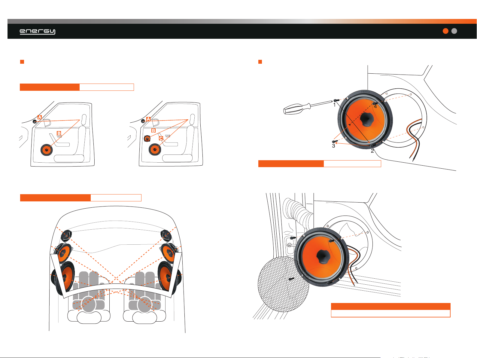
Installazione / Installation
DISTANZE CONSIGLIATE SUGGESTED LENGTH
A = B A = B = C
INCLINAZIONE CONSIGLIATA SUGGESTED ANGLE
Fissaggio woofer e coassiali / Woofer and coaxial fixing
FISSAGGIO ALTOPARLANTI LOUDSPEAKER FIXING
FISSAGGIO ALTOPARLANTI CON GRIGLIA DI SERIE
FACTORY LOCATION LOUDSPEAKER FIXING
04 05
Page 4

Manuale d’uso | Advanced manual
Montaggio EM 100 / EM 100 mounting
FISSAGGIO CON GRIGLIA HERTZ HERTZ GRILLE FIXING
E‘ possibile
rimuovere le flange
Flange is removable
USARE UNA GUARNIZIONE HOW TO USE GASKET
06
Esempi di
montaggio come
canale centrale
in sistemi Audio Video
Installation pattern as
central channel in
Audio Video systems
07
Page 5

Montaggio ET 20 / ET 20 mounting
17
Manuale d’uso | Advanced manual
MONTAGGIO A SUPERFICIE SURFACE MOUNTING
MONTAGGIO IN PREDISPOSIZIONE
FACTORY CUT-OUT MOUNTING
36
30°
60°
MONTAGGIO A FILO DEL PANNELLO FLUSH MOUNTING MONTAGGIO CON SUPPORTO INCLINATO WEDGE MOUNTING
08 09
Page 6

Manuale d’uso | Advanced manual
Regolazione del Rotative High Frequency Contour dei Coax
HERTZ Energy per l’ottimizzazione delle alte frequenze.
Rotative High Frequency Contour tuning for high frequency range
optimization of HERTZ Energy Coax.
240°
Crossover
Rimozione del coperchio
How to remove the cover
PULL
PUSH
Sistema di fissaggio
Fixing system
CX 200 dimensions CX 300 dimensions
OK
102,2
47
63
82,2
9,5
NO
10 11
87
109,8
139,3
69
11,3
Page 7

Collegamenti / Connection
Manuale d’uso | Advanced manual
OK
SISTEMI A 2 VIE 2 WAY SYSTEM
OTHER
CHANNEL
NO
TW LEVEL
+2
0-2
OK
SISTEMI A 3 VIE 3 WAY SYSTEM
OTHER
CHANNEL
TW LEVEL
0 -2
NO
MID LEVEL
+2
0 -2 +2
12 13
Page 8

Manuale d’uso | Advanced manual
Esempi di collegamento / Connection patterns Schema elettrico dei filtri / Crossover electrical diagram
Singolo, in parallelo o misto.
One speaker, parallel or mixed
MIXED
FREE AIR DC
RESISTANCE
1 Speaker
PARALLEL
1
2
3
ET 20 EM 100 EV 130 EV165 EV 165 L
3,40
3,50
2,90
3,00
3,20
22 µF
0,33 mH
3,9 Ω
2,2 Ω
1,50 mH
5,6 µF
0,22 mH
1,8 Ω
3,3 Ω
4,7 Ω
5,6 µF
4,7 Ω
5,6 Ω
6,8 Ω
0,22 mH
0,82 mH
EV 130
EV 165
EV 165 L
EV 570
ET 20
CX 200
CX 300
ET 20
EM 100
Parallel
Mixed
1
1,70
2
1,13
3
0,85
3,40
Misure espresse in Ohm /
1,75
1,17
0,88
3,50
1,45
0,97
0,73
2,90
1,50
1,00
0,75
3,00
1,60
1,07
0,80
3,20
/ Measure in Ohms
14 15
1,50 mH
EV 165
EV 165 L
EV 570
Page 9

Taratura Elettroacustica / Electro-acoustic tuning
Una volta realizzato il sistema, dedicate alcune attenzioni alla messa a punto
dell’impianto e alla taratura dell’amplificazione specifica.
After installing the speakers in your car and checking all connections, you need to spend some time to
tune your system and calibrate your amplifier.
Manuale d’uso | Advanced manual
Gain al massimo
LED sempre accesi
Amplificatore in distorsione
Maximum gain
Leds always on
Distorted amplifier
Gain regolati più bassi
Led che lampeggiano
Amplificatore in funzionamento lineare
Lower regulated gains
Flashing leds on signal peaks
Amplifier in linear functioning area
NO
OK
Regolate il livello del gain dell’amplificatore in modo
da sfruttare tutta la potenza indistorta dell’amplificatore.
Adjust the input sensitivity control tuning the amplifier input
section according to the signal which comes from the source;
this way you exploit the amplifier maximum power without distortion.
ALERT:
Distortion
Dimensionamento del cablaggio / Choosing your cables
Il cablaggio di potenza riveste un ruolo importante poichè influenza direttamente il fattore di
smorzamento del sistema e la qualità del suono; nella tabella allegata potete trovare una indicazione
della sezione del cavo, consigliata in funzione della lunghezza e della potenza applicata.
Power cables are extremely important since they directly affect the system damping factor
and sound quality; in the table below we show cable diameter, which we recommend
according to length and applied power.
La tavola si riferisce alla potenza
continua su un carico di 4 ohm.
Qualora il carico scenda, si dovranno
aumentare proporzionalmente le
dimensioni del cavo.
Flat
0Hz20 200 2K
Evitate l’utilizzo del loudness o di equalizzazioni in gamma bassa.
Avoid using loudness or excessive equalization.
16 17
The table refers to continuous power
with 4 Ohm load. If load decreases,
the cable size needs to be
proportionally increased.
Potenza applicata / Applied power
Lunghezza del collegamento / Connection length
Diametro del cavo / Cable diameter
Page 10

TECHNICAL SPECIFICATIONS
Manuale d’uso | Advanced manual
ET 20
EM 100
EV 130
EV 165
EV 165 L
ESK 130
ESK 165
ESK 165L
ESK 570
ESK 163L
ECX 87
ECX 100
ECX 130
ECX 165
ECX 570
ECX 690
Component
Tweeter
Cone Midrange
Woofer
Woofer
Woofer
2 Way System
2 Way System
2 Way System
2 Way System
3 Way System
2 W Coaxial
2 W Coaxial
2 W Coaxial
2 W Coaxial
2 W Coaxial
3 W Coaxial
mm
Size
20 (3/4”)
100 (4”)
1/4
)
130 (5”
1/2
165 (6”
)
1/2
)
165 (6”
Tweeter 20 (3/4”)
Woofer 130 (5”
Tweeter 20 (3/4”)
Woofer 165 (6”
Tweeter 20 (3/4”)
Woofer 165 (6”
1/4
)
1/2
)
1/2
)
Tweeter 20 (3/4”)
Woofer (5x7”)
Tweeter 20 (3/4”)
Midrange 100 (4”)
Woofer 165 (6”
Tweeter 15 (19/32”)
Woofer 87 (3”
1/2
)
1/2
)
Tweeter 20 (3/4”)
Woofer 100 (4”)
Tweeter 20 (3/4”)
Woofer 130 (5”
Tweeter 20 (3/4”)
Woofer 165 (6”
1/4
)
1/2
)
Tweeter 20 (3/4”)
Woofer (5x7”)
Supertweeter 15 (19/32”)
Tweeter 40 (1,5”)
Woofer (6x9”)
peak
100
150
100
140
140
150
200
200
200
250
60
80
100
140
140
200
continuous
program
Power
handling
(Watt)
100W@3,5k
Hz12dB Oct.
75
50
70
70
75
100
100
100
125
30
40
50
70
70
100
ohm
Impedance
4
2k - 23k
4
400 - 14,5k
4
65 - 8k
4
60 - 8k
4
50 - 6k
4
65 - 23k
4
60 - 23k
4
50 - 23k
4
60 - 23k
4
50 - 23k
4
120 - 21k
4
70 - 23k
4
65 - 23k
4
60 - 23k
4
60 - 23k
4
40 - 23k
Hz
Frequency
response
dB/SPL
mm
Sensitivity
Outer
diameter
mm
Mounting
hole diameter
mm
mm
Magnet size
Total depth
mm
Mounting
depth
A BCDE
33,5
102
130
165
165
130
165
165
195
165
87
102
130
165
195
237
36
95
120
145
145
120
145
145
184
145
80
95
120
145
184
225
23,5
58
80
85
85
80
85
85
85
85
60
75
80
85
85
100
91
90
91
93
92
91
93
92
93
92
87
88
91
93
93
95
11
19
28
33
56
60
66
72
66
72
56
60
66
72
66
72
65
72
66
72
35
46
46
60
73
56
77
66
77
65
98
78
kg
Weight of
one
component
0,033
0,236
0,754
0,911
0,920
0,754
0,911
0,920
0,948
0,920
0,317
0,573
0,794
0,954
0,988
1,420
mm
Voice coil
diameter
20
25
25
25
25
25
25
25
25
25
25
25
25
25
25
25
Magnet
Neodymium
REN
Neodymium
REN
High density
flux ferrite
High density
flux ferrite
High density
flux ferrite
High density
flux ferrite
High density
flux ferrite
High density
flux ferrite
High density
flux ferrite
High density
flux ferrite
High density
flux ferrite
Cone / Dome
Tetolon
V-Cone,
treated paper
V-Cone,
treated paper
V-Cone,
treated paper
V-Cone
non pressed paper
Water-repellent
paper
RHFC on
treated paper
RHFC on
treated paper
RHFC on
treated paper
RHFC on
treated paper
Water-repellent
paper
D
E
B
A
D
E
C
B
A
D
E
C
B
A
18 19
 Loading...