

Page 1
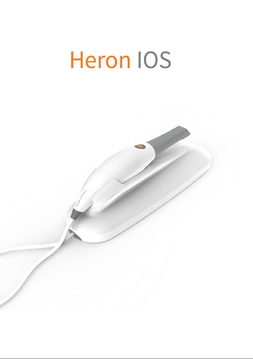
A Digital Impression Scanner Solution
User Manual
Page 2
Page 3

2
Table of Contents
Table of Contents ................................................................................... 2
1. Introducing the Heron™ IOS Solution ............................................ 5
1.1. Introduction ................................................................................ 5
1.2 Indications supported ............................................................... 5
1.3 Certification and compliance ................................................... 5
1.4 Regulatory .................................................................................... 6
1.5 Intended Use ................................................................................ 6
1.6 Classifications .............................................................................. 6
2. What’s in the Box ................................................................................ 7
3. System Requirements and Specifications .................................... 8
3.1 System Specifications ................................................................ 8
3.1.1 Scanner ................................................................................. 8
3.1.2 Scanning Process ............................................................... 8
3.1.3 Software & Lab Integration ............................................... 9
3.2 Computer Requirements........................................................... 9
3.2.1 Required Software and Misc. ........................................... 9
3.2.2 Required Hardware ............................................................ 9
3.3 Environment Conditions ........................................................ 10
3.4 Power Input ............................................................................... 10
3.5 Reusable Tips ............................................................................ 10
3.6 Scanner – Base and Handpiece ............................................ 10
4. How to Connect & Set up the Heron™ IOS Solution
..................... 11
4.1 Setting Up and Connecting the Heron™ IOS ..................... 11
4.2 Heron™ IOS Components Overview .................................... 13
4.3 Settings....................................................................................... 13
Page 4

5. Operating the Heron™ IOS Solution ............................................ 15
5.1 Getting Started .......................................................................... 15
5.1.1 Case Management Software Overview ............................. 15
5.2 Indication workflows ............................................................... 16
5.2.1 Create new order .............................................................. 16
1.2.2 Choose material and color ............................................ 18
5.3. Important things to know before scanning ....................... 19
5.4 Operating the scanner ............................................................. 20
5.4.2 Mandibular and Maxillary Scanning ............................. 21
5.4.3 Bite Alignment................................................................... 22
5.4.4 Tip ........................................................................................ 23
5.5 Communication with the Lab ................................................ 24
5.6 Scanning Tools ......................................................................... 25
5.7 Editing Tools ..................................................................... 26
6. Understanding the Software Symbols .................................. 27
7. Maintenance ..................................................................................... 28
7.1 Cleaning the Handpiece .......................................................... 28
7.2 Cleaning and Sterilization of Tip ........................................... 28
7.3 Disposal ...................................................................................... 30
7.4 Calibration .................................................................................. 30
8. Safety Guidelines and Warnings ................................................... 32
8.1 Warnings and Symbols ............................................................ 32
8.2 General Guidelines ................................................................... 32
8.3 General Warnings ..................................................................... 33
8.3.1 System Modification ........................................................ 33
8.3.2 Approved Software .......................................................... 33
8.3.3 Equipment Failure............................................................ 33
8.4 Mechanical Hazards ................................................................. 33
Page 5

4
8.4.1 Moving Parts ..................................................................... 33
8.4.2 Dropped Equipment ....................................................... 34
8.4.3 Base .................................................................................... 34
8.5 Electrical Safety ........................................................................ 34
8.5.1 Electrical Shock ................................................................ 34
8.5.2 Stress on Cables ............................................................... 34
8.6 Eye Safety................................................................................... 35
8.7 Hygiene ...................................................................................... 35
8.8 During Systems Operation ..................................................... 35
8.9 Symbols on the Heron and Transport Case ....................... 36
9. Support, Warranty and Repair Service ................................. 37
9.1 Support ...................................................................................... 37
9.2 Standard Warranty .................................................................. 37
9.3 Repair Service ........................................................................... 37
9.4 Out of Warranty Repair Service ............................................. 38
9.5 Troubleshooting Guide ........................................................... 38
Page 6

1. Introducing the Heron™ IOS Solution
1.1. Introduction
Thank you for purchasing the Heron™ IOS solution from 3DISC.
The Heron™ IOS solution is designed and developed to produce highquality digital intraoral scans, or models, for dental restoration or
analysis.
The Heron™ IOS solution is designed with you as a dentist and your
patient in mind. The scanner is lightweight, small and easy to use,
enabling a fast, accurate scanning and great patient experience. The
Case management application is order management as you know it
and designed for easy and intuitive use. Enjoy your new intraoral
scanner solution!
1.2 Indications supported
Heron™ IOS can be used for the following indications:
• Anatomy crowns
• Copings
• Provisional (Temporary) crowns
• Pontics (Anatomical, reduced and provisional)
• Inlays/Onlays
• Veneers
• Wax up (anatomical and reduced)
• Implants (Single abutments)
• 3-unit Implant bridges
• Up to 5-unit bridges
1.3 Certification and compliance
The system has been tested and conforms to the following standards:
• IEC 60601-1, Medical electrical equipment - Part 1: General
requirements for basic safety and essential performance
• IEC 60601-1-2, Medical electrical equipment - Part 1-2:
General requirements for basic safety and essential
performance - Collateral Standard: Electromagnetic
disturbances - Requirements and tests
• IEC 62471, Photobiological safety of lamps and lamp systems
Page 7
6
1.4 Regulatory
The Heron™ IOS is manufactured and marketed in accordance with US
FDA Regulations and EU Medical Device Directive 93-42-EEC.
1.5 Intended Use
The Heron™ IOS is an optical impression system. It is used to record
the topographical characteristics of teeth, dental impressions, or stone
models for use in the computer-aided design (CAD) and computeraided manufacturing (CAM) of dental restorative prosthetic devices.
CAUTION:
Federal law restricts this device to be sold by or on the
order of a Dentist.
WARNING:
Unintended use of the system can result in physical injury
to the patient and operator, and damage to the system.
1.6 Classifications
The Heron™ IOS system has the following classifications:
• Protection against electrical shock: Type B Applied Part
• Protection against harmful ingress of water: Ordinary equipment
(IPX0)
• Safety of application in the presence of a flammable anesthetic
material with air or with oxygen or nitrous oxide: Equipment not
suitable for use in the presence of a flammable anesthetic mixture
with air or with oxygen or nitrous oxide.
Page 8
2. What’s in the Box
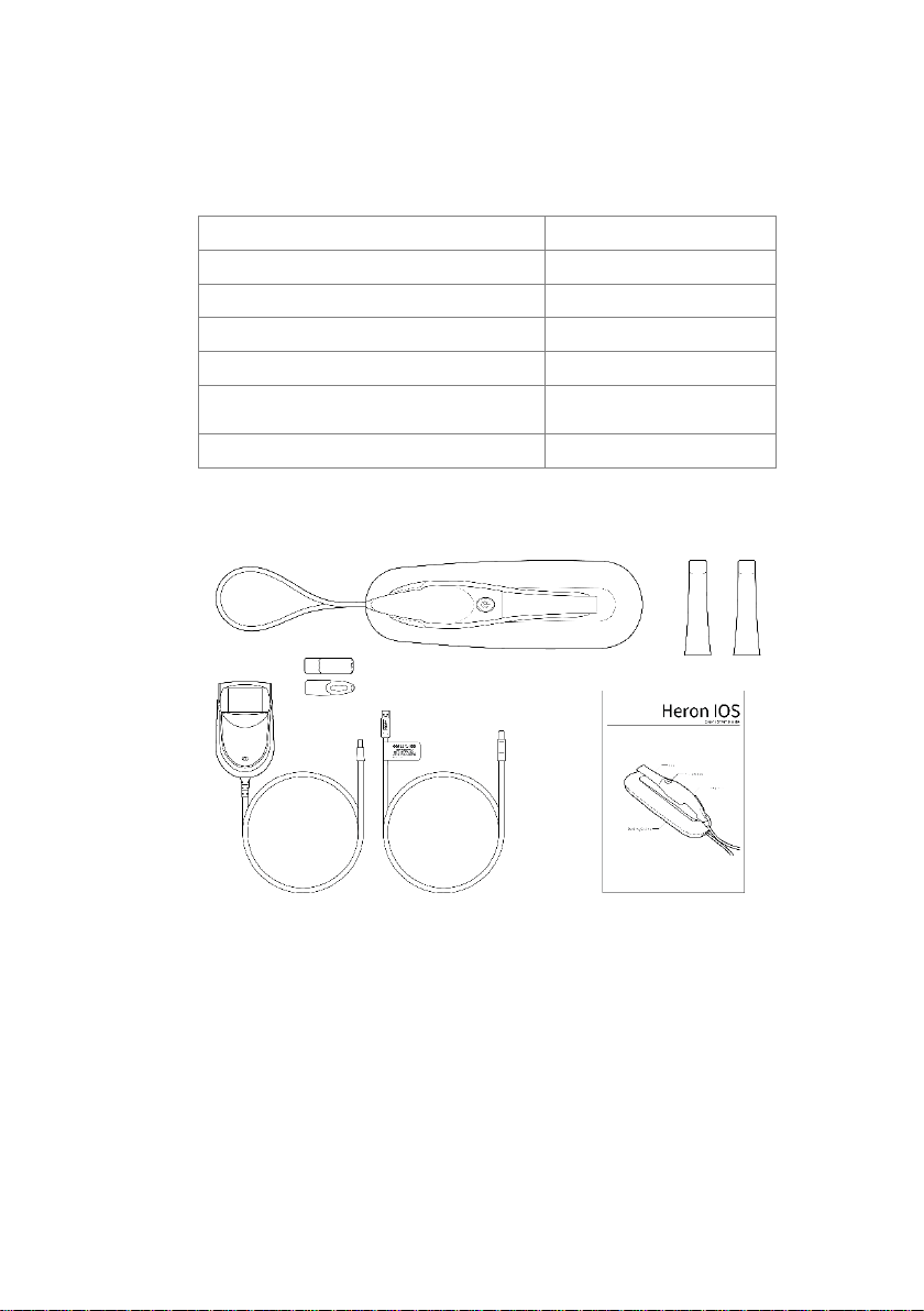
The Heron™ IOS system includes the following:
Save the Box: It is highly recommended that you store the box in a safe
place and do not throw it away. The box is optimal for any necessary
transportation or shipment of the Heron™ IOS.
Name
Part Number
Heron™ IOS System (Includes 3 Tips)
IOS-FP-71-001
USB 3.0 Cable
IOS-CP-00-043
AC/DC Power Adapter
IOS-CP-00-088
Software Licensing Dongle, QuantorClinic™
IOS-CE-71-013
Software Licensing Dongle
(Case management software only, no CAD)
IOS-CE-71-016
Quick Guide
IOS-FPM-71-002
Page 9

8
3. System Requirements and Specifications
3.1 System Specifications
3.1.1 Scanner
3.1.2 Scanning Process
Scanner Type
Hand-held (chairside) scanner that creates
optical impressions for dental restorations.
Design
Compact, lightweight, ergonomic – designed to
be operated with little physical effort.
Dimensions Base
Size: L 306mm, W 98mm, H 72mm
Dimensions Scanner
Weight: 150 grams
Size: L 256mm, W 43mm, H 43mm
Power Requirement
DC5.0V / 4A (Power supply included)
Scanner Tip
Reusable, sterilize using steam autoclave
Heating Element
Prevents formation of fog on the optics
Acquisition Method
Intraoral camera – active stereo imaging
Color Scanning
24-bit (8-bit per channel)
Tooth Preparation
No powder or spray required
Scanning Principle
Continuously scanning and accumulating
(stitching) depth and color data
Distance Scanner - Tooth
0 – 12mm
Possible contact duration by
operator
10 min ≤ t
Note: May vary with hardware configuration
Operator Accessible Part
Handpiece
Possible contact duration by
patient
10 min ≤ t
Patient accessible part (Type B
Applied Part)
Tip
Computer – Scanner Interface
USB 3.0
Page 10
3.1.3 Software & Lab Integration
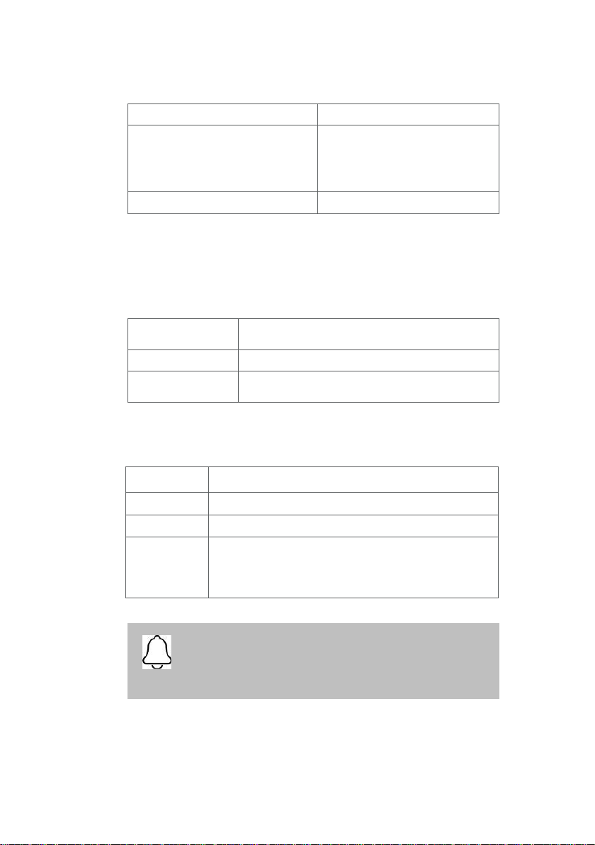
3.2 Computer Requirements
3.2.1 Required Software and Misc.
3.2.2 Required Hardware
NOTE:
AMD GPU’s are
NOT
compatible with the Heron™ IOS. Not
meeting minimum hardware requirements will affect the
performance of the scanner.
Output File Format
STL, PLY, OBJ
Compatibility with CAD/CAM Systems
Open Architecture
Output format STL, PLY, OBJ
Compatible with most Dental CAD
systems
Case Management application Interface
Touchscreen support
Operating System
Windows 10 (Excluding Windows 10 S, now defunct)
Administrative rights required
Disk Space
100 GB of free disk space or greater
Ports
1 x USB 3.0 port (SuperSpeed)
2 x USB port
CPU Type
Intel i7 - 4 Cores or greater (e.g. i7 8700)
CPU Clock
2.8 GHz clock or greater
Memory
16 GB of RAM or greater (DDR4 or better)
GPU
NVIDIA GeForce Graphics Processor000 Series (GTX): 1070 or
Greater
1000 Series (GTX): 1070 or greater - At least 6 GB video memory
2000 Series (RTX): 2060 or greater - At least 6 GB video memory
Page 11

10
3.3 Environment Conditions
3.4 Power Input
The power adapter input is 5V DC, 100-240V AC, 50-60Hz.
3.5 Reusable Tips
Scanner tip is autoclavable up to 50 times in a steam autoclave. See
chapter 6.
3.6 Scanner – Base and Handpiece
The scanner body consists of the Base and Handpiece, which are
connected by a flexible, non-detachable cable.
Operating Temperature
10°C ~ 40°C
Operating Relative Humidity
10% ~ 80% (non-condensing)
Storage Temperature
- 20°C ~ 60°C
Storage Relative Humidity
10% ~ 80% (non-condensing)
Indoor use only
Installation Category
1
Pollution Degree
2
Ingress of Liquids
IPXO
Protective Class
Class IIIb
Overvoltage category
I (Supplied from output DC source, max. 5
Vdc, 600 mA) of notebook or non-medical
grade PC certified by IEC60950-1
Max. working condition
Continuous cycles with image capture and
transmission from/to Notebook or nonmedical grade PC.
Other possible accessories
(IEC60601-1 3rd, Cl. 16)
Notebook with AC/DC Adapter.
Equipment Maintenance
No user maintenance is required, and no
user service is allowed. Please contact
technical support if there is a problem.
Cleaning
Do not try to clean the inside of the device.
Refer to Chapter 6 for cleaning and
sterilization.
Page 12
4. How to Connect & Set up the Heron™ IOS Solution
4.1 Setting Up and Connecting the Heron™ IOS
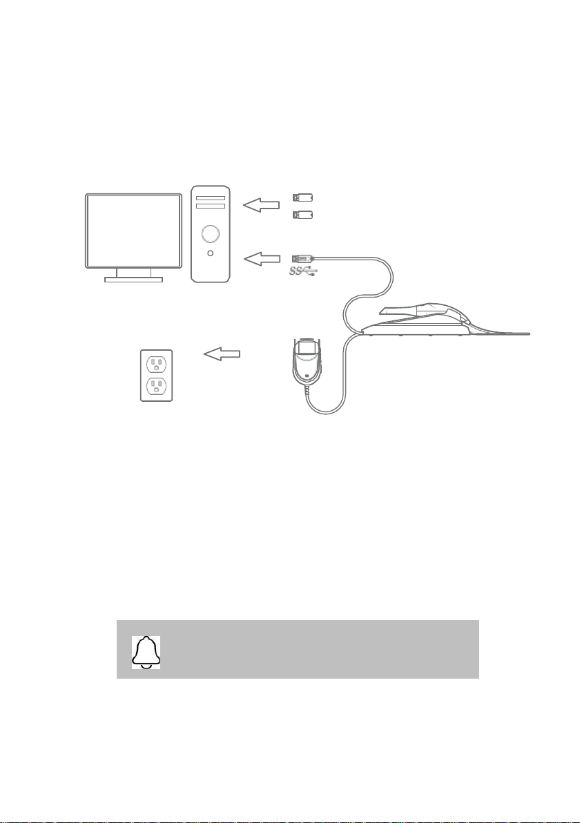
Connection Guide
Plug in the two USB
software dongles (Gray
and Blue).
USB 3.0 Cable
Heron™ IOS
AC/DC
Power Adapter
Install the system according to the following steps:
Step 1: Place the base on a flat, stable surface and place
the Heron™ IOS handpiece securely in its base.
Step 2: Connect the AC/DC power adapter cable to the Base; the
connector socket is located underneath the Base.
Step 3: Connect the provided USB 3.0 cable to the Base;
the connector socket is located underneath the Base.
Step 4: Connect the other end of the USB cable to the computer.
NOTE:
Using a USB cable other than the one provided may result in
system malfunction or reduced performance.
Page 13
12
Step 5: Connect the AC/DC power adapter to a power outlet.
NOTE:
It is strongly recommended to plug the USB cable to a USB
port located at the back of the computer; not doing so may result
in system malfunction or reduced performance.
Make sure to use a USB port that is compatible with USB 3.0
(SuperSpeed), usually indicated by the following symbol: ;
not doing so may result system malfunction or reduced
performance.
If using a laptop computer, make sure the power supply is
connected to an outlet and not running on battery power.
WARNING:
Unsuitable Installation sites
• Locations with excessive humidity or dust
• Locations subject to high temperature
• Locations subject to shaking or vibration
• Locations exposed to considerable electrical or magnetic
noise, or other forms of electromagnetic energy
Page 14
4.2 Heron™ IOS Components Overview
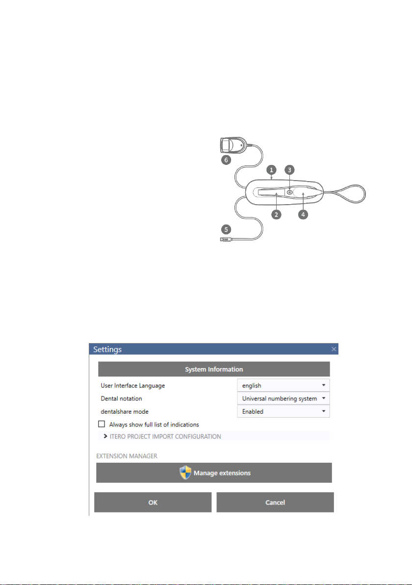
Please review the Heron™ IOS features shown in this section. This will
help you locate the features when they are described in sections 5-7.
4.3 Settings
After starting the QuantorClinic™ software, you can access the settings
menu, that contains the following options:
1
The base and scanner
2
Tip 3 Scan Button
4
Handpiece
5
USB 3.0 Cable
6
AC/DC Power Adapter
Page 15

14
User Interface Language
This function allows you to set your language preference. The system is
available in the following languages:
English
French
German
Greek
Italian
Japanese
Korean
Portuguese
Russian
Spanish
Turkish
Dental Numbering Systems
This setting allows you to select the tooth numbering system of your
preference.
The following numbering systems are available:
• FDI World Dental Federation notation
• Universal numbering system
• Palmer notation
Dentalshare Mode
• Enable
• Disable
• LAN client connection
• Toggle on-off full list of indications
• Extension management
Page 16
5. Operating the Heron™ IOS Solution
5.1 Getting Started
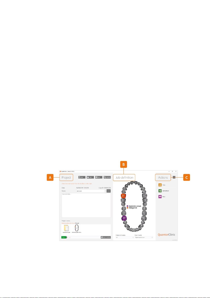
5.1.1 Case Management Software Overview
A. Patient Information
The case management screen is used to record patient
information and to create notes for your lab. Patient name and
RX notes can be filled out in the ‘Project’ Section (A), or a returning
patient can be selected from the ‘Load’ tab.
B. Job definition
The ‘Job Definition’ section (B) is used to record your desired
restoration and to indicate whether a single arch scan and/or a
bite alignment is needed.
C. Procedure
The ‘Actions’ section (C) is used to begin your scan, export scan
files to your lab using ‘dentalshare’ or to print a pdf of the patient
RX form.
Figure 1
Page 17

16
5.2 Indication workflows
QuantorClinic™ supports the following restorations and appliances:
5.2.1 Create new order
To create a new patient order for the above-mentioned indications, follow
the steps below.
Anatomic crowns
Copings
Provisional crowns
Anatomical pontics
Reduced pontics
Provisional pontics
Inlays/Onlays
Implant abutments
3-unit implant bridges
Up to 5-unit bridges
Orthodontic aligners
Nightguards
Splints
Retainers
Bleach trays
Sleep appliances
Page 18
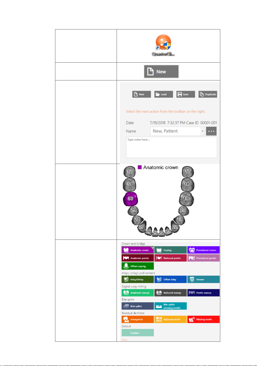
1. Start the Case
management
application, called
QuantorClinic™.
2. Click on the ‘New’
tab (Figure 1: A).
3. Enter a new patient
or select an existing
patient under the
“load” tab.
4. In the ‘Job
Definition’ section
(Figure 1B) select the
desired tooth/teeth
for restoration.
5. Once you have
selected your tooth
a library of
procedures will
appear. Select the
needed restoration
from the list.
Page 19
18
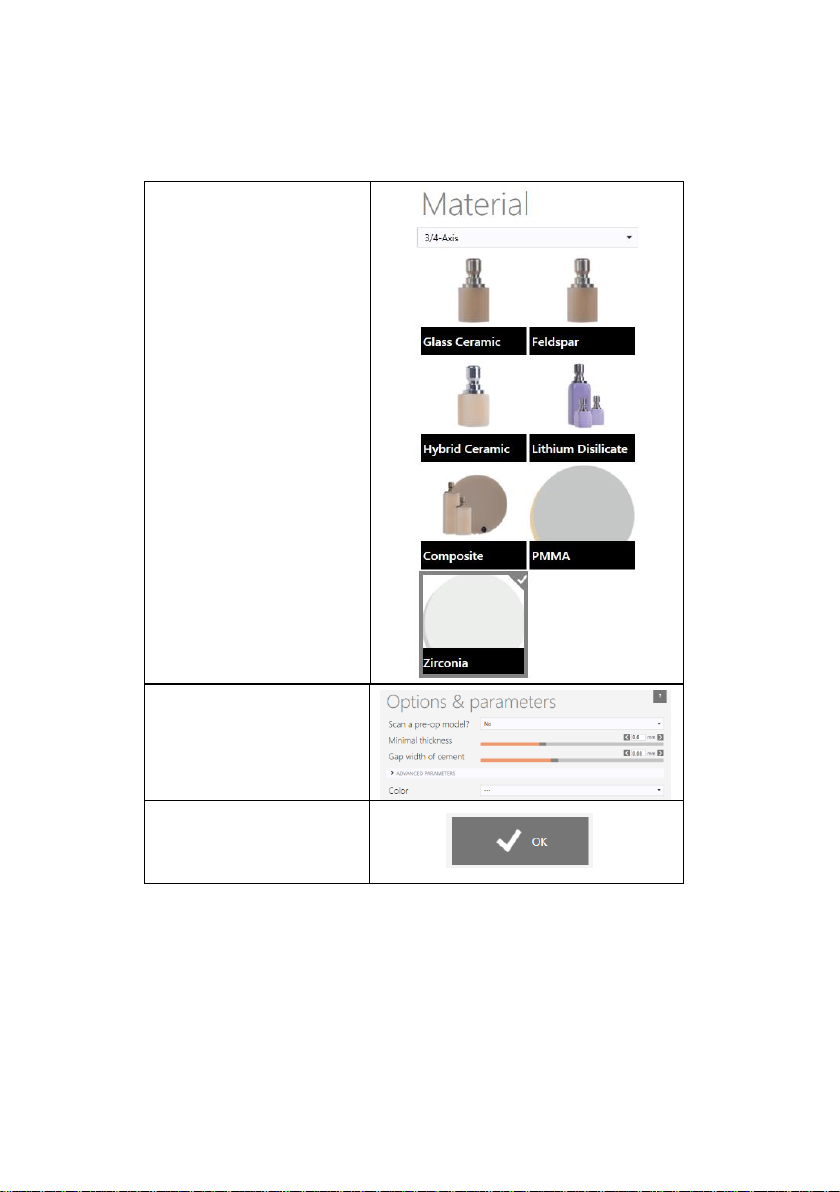
1.2.2 Choose material and color
2. Customize your
parameters or keep them
on the default setting.
3. Click ‘OK’ to confirm
selection.
1. You may choose your
preferred material;
however, this selection is
optional and not required
as your lab will likely
make this decision.
Page 20
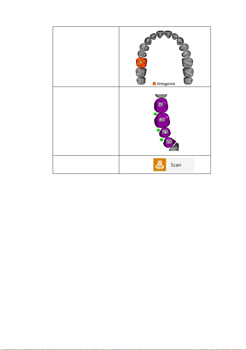
4. If a bite registration is
needed, you must select
a tooth on the opposing
arch, labeling it as an
‘antagonist’.
5. If you want to create a
bridge connection, click
on a second tooth/teeth
and then click on the
small green circle to
connect them.
6. Save order
7. Start scanning
5.3. Important things to know before scanning
If doing a crown, prepare the tooth with a gingiva retraction cord. This
is optional however highly recommended. Prior to scanning, remove
the retraction cord and dry the surface of any blood or saliva using an
air/water syringe or a 2x2 gauze.
Page 21
20
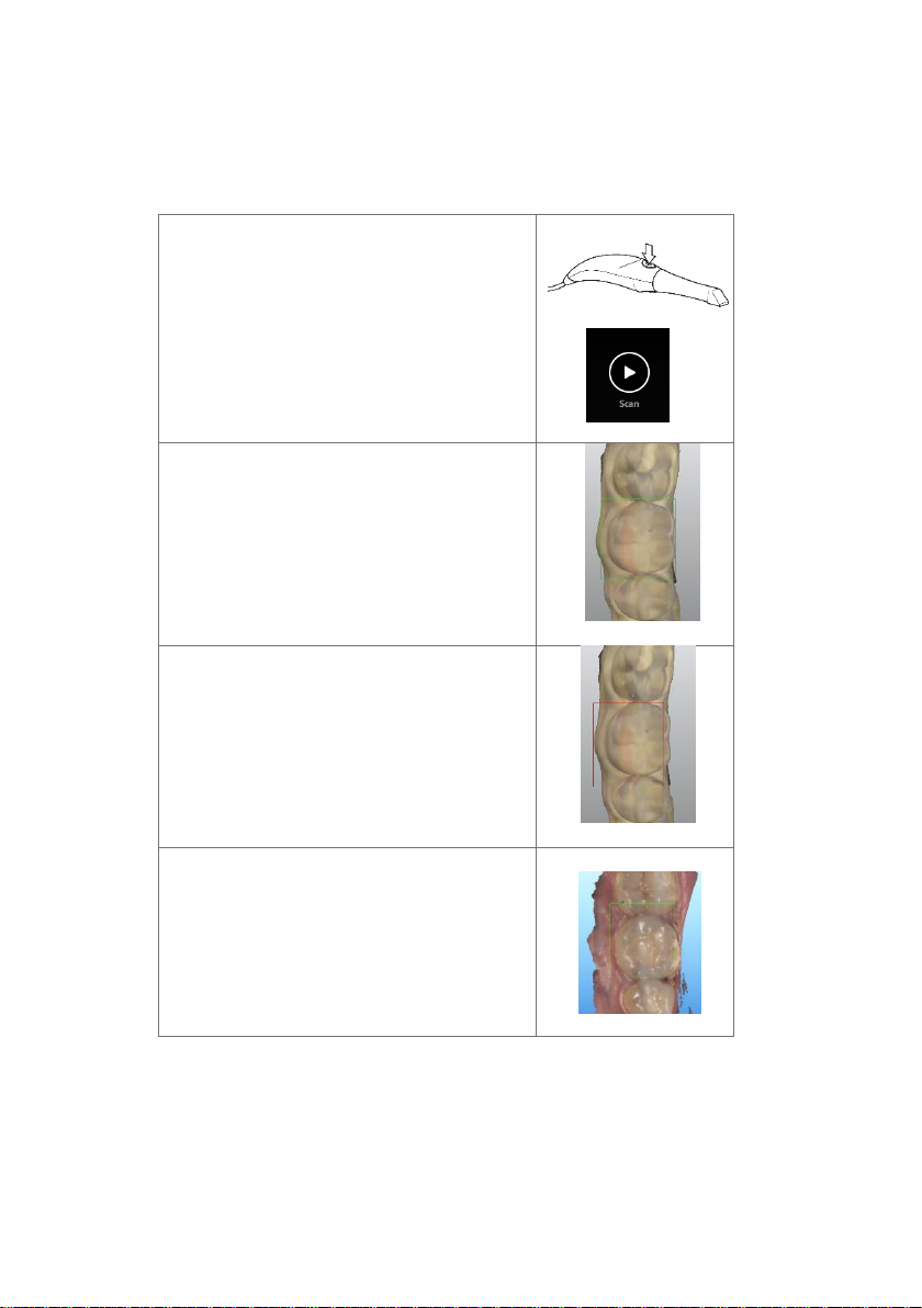
5.4 Operating the scanner
5.4.1 Scanning
1. Start Scan
To begin scanning, press the button on the top of
the scanner or you may click ‘scan’ on the right
tool bar window.
Recommended distance from tip to tooth is from
0-12 mm.
2. Green Image
When the green box is present, it indicates the
scan is successfully stitching together. To
maintain the green indicator, remain steady and
precise with your movements.
3. Red Image
In the event of a red box, the scan has lost it’s
track and is no longer stitching the scan together.
This is caused by unsteady and sudden
movements of the handpiece as well as a lack of
cheek/tongue retraction.
4. Restart
If your scan has lost track, simply place the scan
tip on the occlusal surface of an already scanned
tooth. The occlusal surface has the most detail
and will allow the software to recognize its
position quickly. Facial surfaces are difficult to
recognize as their surfaces are flatter.
Page 22
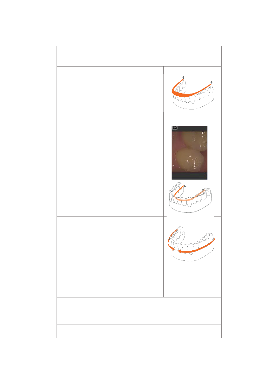
5.4.2 Mandibular and Maxillary Scanning
1. Begin your scan
by starting on the arch of chosen restoration. If scanning
both arches, you may select either arch to begin.
2a. For a full arch
, follow a scan path of occlusal,
lingual then buccal. Beginning on the posterior
terminal molar, working across the entire
occlusal plane of the arch, you will end at the
opposing terminal molar. When scanning the
anterior region, ensure to slightly roll the scan tip
at least 1mm over the incisal edges to capture
some facial surface.
2b. The live view window
to the left is the main
point of reference. While scanning, what is
shown in the live window will appear on the 3D
image. Ensure the anatomy of the tooth is
centered in the view window with little to no
cheek or tissue present.
3. When finished scanning the occlusal,
starting
at the terminal molar, slightly rotate the scanner
to 45 degrees scanning the entire lingual surface
of the entire arch ending at the opposing
terminal molar.
4. To scan the buccal surface
, again beginning
on the posterior terminal molar, you will rotate
at 45 degrees scanning the buccal segment
stopping at the midline. You will repeat the
process on the opposing terminal molar to
connect the midlines. Ensure you do not scan all
the way around the entire arch on the buccal
facial surfaces. Finalize in scanning the buccal
side of the molars with the scanner in a 90
degree angle being sure to capture at least 5mm
of gingiva.
5.
When scan is complete, turn the scanner off by the power button on the
handle of the scanner. If scanning both arches, select the other arch now in
the software.
6. Repeat
the same scan path and strategy for both arches.
Page 23
22
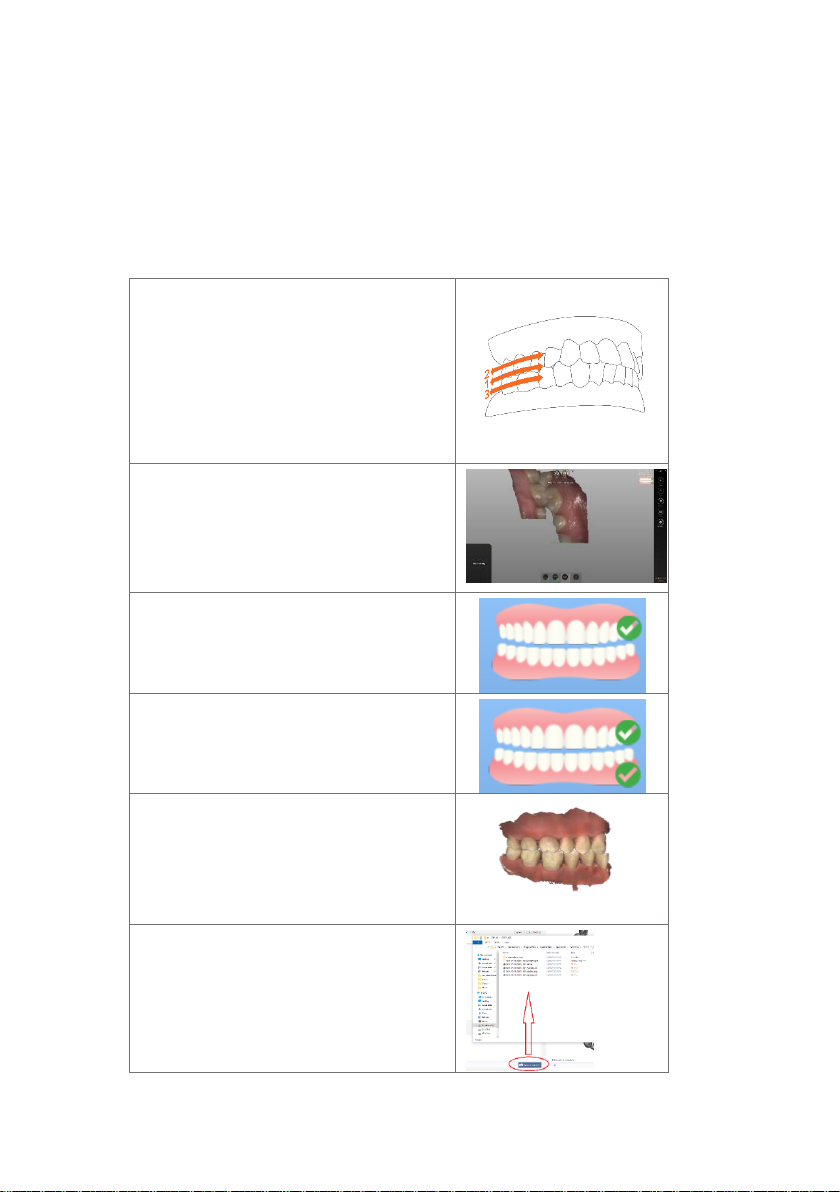
5.4.3 Bite Alignment
In the event of a quadrant scan, you will be asked to scan only the side
of the quadrant. When doing full arch scans, you will be prompted to
scan bilateral.
When selecting ‘bite’, allow a few seconds for the arch scans to load.
1. Scanning the occlusion
1a.
To capture the bite, you will begin
scanning on the central molars capturing both
mandibular and maxillary teeth in the first
pass. Then scan only the Maxillary molars and
gingiva till the arch is locked. Move down to
scan only the Mandibular molars and gingiva
untill arch is locked and Heron stops.
1b.
Once the arch is locked, the arch will get
the initial scan overlayed and a green
checkmark will apper like described below
indicating you are finished scanning that arch.
Once the arch is complete, repeat the process
for the opposing arch.
1c.
When the arch is finalized, a green check
mark will appear on the corner of the image of
the arch you captured.
2.
When both arches have registered
successfully, a green check mark will appear
on the corner of each arch image.
3a
. When the bite alignment is complete, you
may rotate the 3D image to confirm correct
patient occlusion.
3b
. In the event you may feel that the
alignment needs modification, you or your lab
can upload the file into a design software for
fine tuning. Access the files directly in Explorer
like this.
Page 24
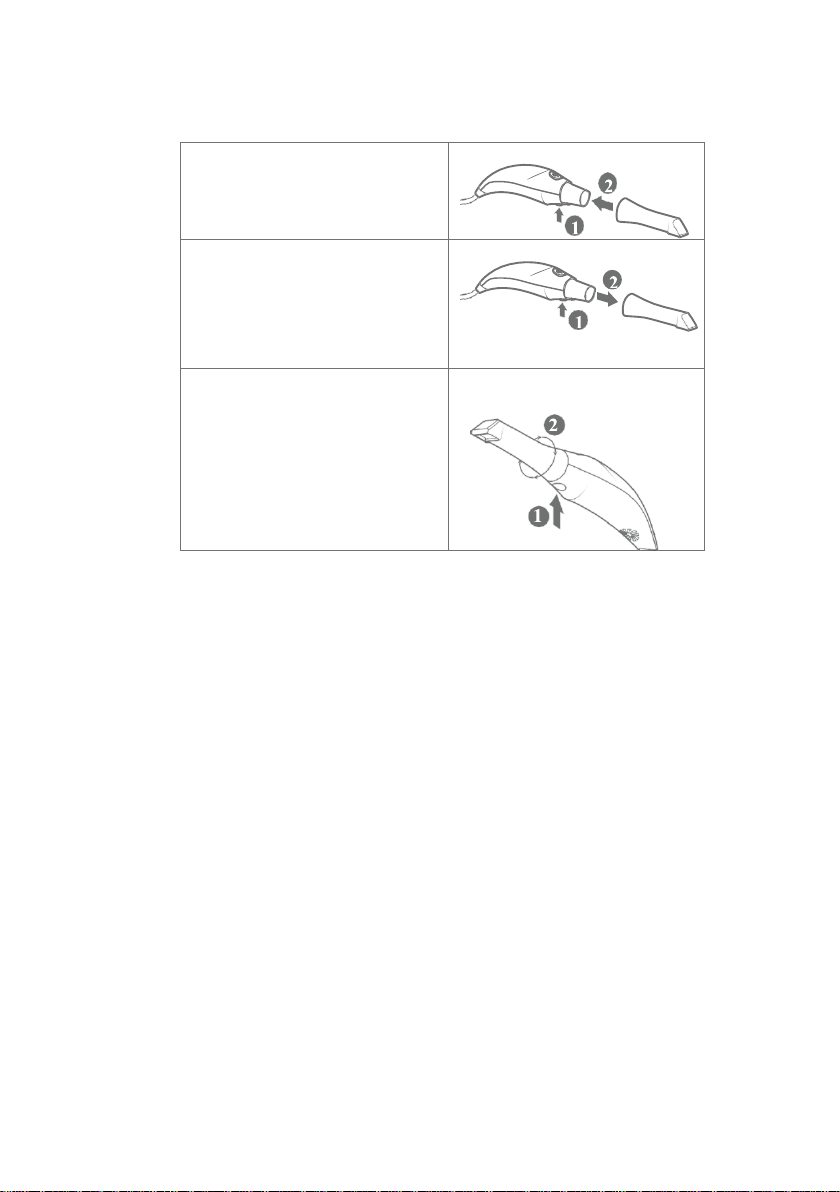
5.4.4 Tip
1. Attach
the tip with the mirror side
facing downward. Firmly press the tip
onto the scanner until you hear it lock
into place.
2. Detach
the tip by pressing the
button located on the bottom of the
handpiece (1) while pulling away from
the scanner (2).
3. Rotate
the tip 180 degrees for
maxillary scanning by pressing the
button (1) located on the bottom of
the handpiece.
*
It is not required to rotate the tip for
maxillary scanning.
Page 25
24
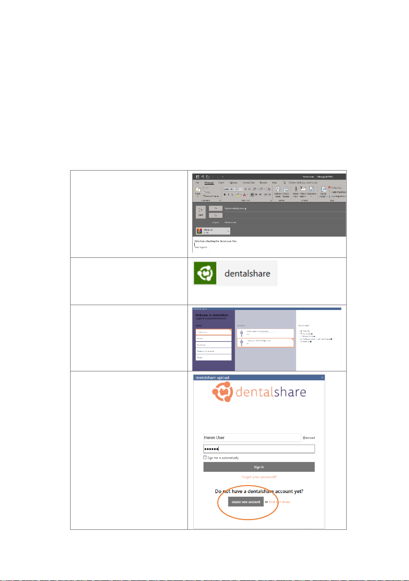
5.5 Communication with the Lab
The Case Management application, QuantorClinic™, contains two
built-in methods for communicating with the lab. You can either
1. Access the scans directly by clicking the “Open in Explorer” tab,
select desired files and drag and drop in your desired platform.
2. Use dentalshare (your lab must be an Exocad recipient in order to
receive files from dentalshare):
1.
Share files directly by locating
the file in the “open in Explorer”
tab and copying the file into
Dropbox, wetransfer.com, email
etc.
2a.
Share files via Dentalshare
by clicking the ‘dentalshare’ icon
located under the ‘Actions’
section.
2b.
If you are already a member
of dentalshare, you will simply
click on ‘collaboration’ then
select your files you wish to
export under the ‘scan data’ list.
2c. Create new account
You can create an account by
clicking ‘Create new account’ you
will then need to invite your lab
as a recipient.
Page 26
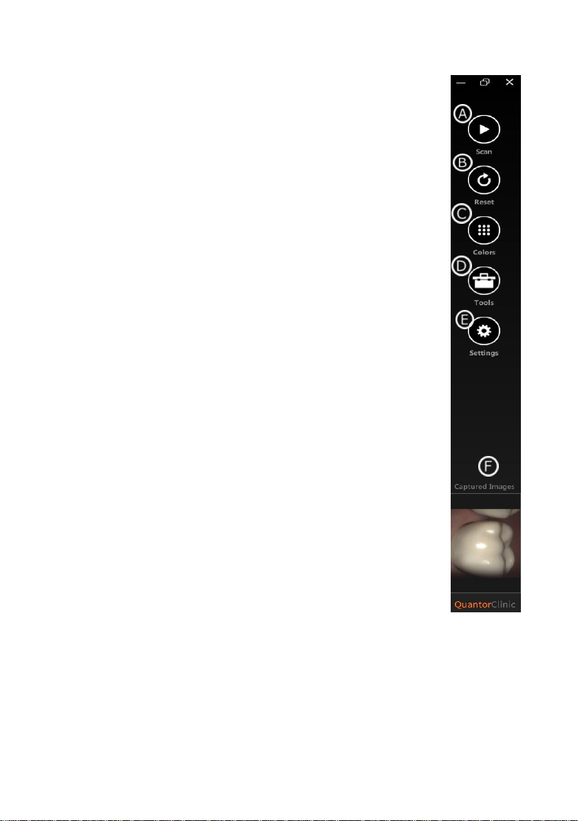
5.6 Scanning Tools
A Scan
Enables the start of scanning as well as pausing the scan.
B Reset
Reset will delete the current scan.
C Colors
You may customize the screen and background colors
D Tools
Offered tools consist of a measuring tool, box deletion, eraser
and brush for cleaning excess tissue or glove images as well as
any distortions.
E Settings
Settings will allow you to change the file format and adjust the
response sound of the scanner.
F 2D images
On your keyboard, select the key “C” to capture an intra oral
photograph to share with your lab.
Page 27
26
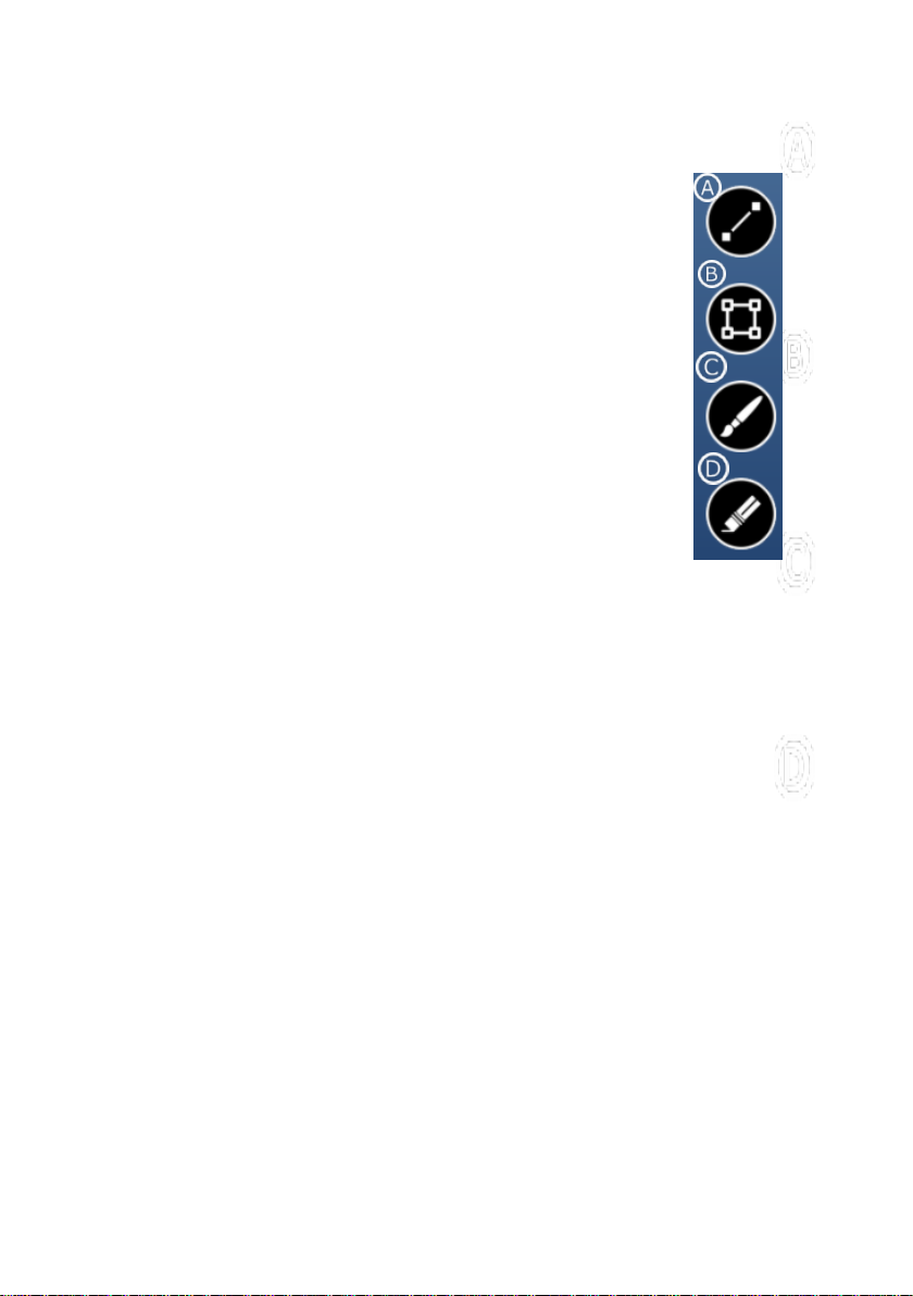
5.7 Editing Tools
A Measuring
This took is used for measuring interproximal spacing for
implant work or orthodontics. On your keyboard hold down
Ctrl and select the measuring starting point. Drag the tool to
your desired location and release the key.
B Box
This tool is used to select sections of the model to delete or
crop. After selecting the tool, Ctrl-Click to select an area and
Alt-Click to deselect an area. Press the ‘D’ or Delete key on
your keyboard to remove the selected portion. Press the ‘C’
or Insert key to crop and remove everything outside the
selected portion.
C Brush
As with the Box selection tool, you can use this tool to select
sections of the model to delete or crop. Ctrl-Click to select and
use Alt-Click to deselect. Use the ‘D’ or Delete key on the keyboard
to remove the selected portion, and the ‘C’ or Insert key to crop and remove
everything outside the selected portion. Use the +/- keys to increase or
decrease the size of the brush.
D Eraser
The Eraser tool is used to remove unwanted portions of the model. Select the
area of interest and Ctrl-Click to remove or Alt-Click to add back. As with the
Brush tool, using the +/- keys will change the size of the brush. Any changes
made using the Eraser tool are finalized whenever another tool is selected, or
when the Eraser tool is deselected.
Page 28
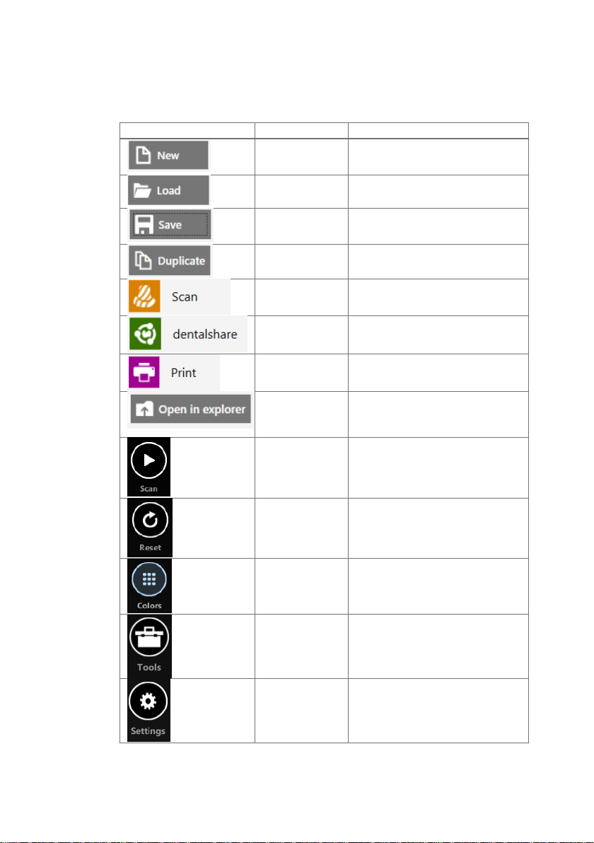
6. Understanding the Software Symbols
New Project
Create a new patient
Load Project
Open and existing patient
Save Project
Save once order form is complete.
Duplicate
Project
To send the same project to
multiple labs.
Scan
To open the scanning window.
Dentalshare
To export scan files to lab via our
cloud solution
Print
To print patient RX or create PDF
file.
Open in Explorer
To access the 3D scan files so they
can be manually transferred to a
lab (without using Dentalshare).
Scan /stop
To start or stop your scan. This is an
alternative method to using the
button located on the scanner
itself.
Reset
To delete your current scan and
start new.
Colors
To customize background colors.
Tools
To enable editing tools
Settings
To select file format and change
response sound.
Symbol
Name
Intended use
Page 29

28
7. Maintenance
7.1 Cleaning the Handpiece
The entire body, cord and base of the scanner must be wiped down
using a Federal Environmental Protection Agency (EPA) approved
disinfectant that is labeled and specified for tuberculocidal/
mycobactericidal activity.
NOTE:
All components of the scanner (excluding the tips) must be
wiped down and not sprayed. Avoid getting any moisture, alcohol
or disinfectant inside the open scanner chamber.
Recommended and approved surface disinfectants:
• Birex Wipes: TB Claim= 10 minutes- ‘Phenolic (Dual) Water-
Based’
• Prospray Wipes: TB Claim=10 minutes- ‘Phenolic (Dual)
Water-Based’
• Cavicide Wipes: TB Claim=3 minutes- ‘Phenolics (Dual)
Alcohol-Based’
• DisCide ULTRA Wipes: TB Claim-1 minute- ‘Phenolics (Dual)
Alcohol-Based’
• Maxiwipe Germicidal Cloth: TB Claim=5 minutes- ‘Phenolics
(Dual) Alcohol-Based’
7.2 Cleaning and Sterilization of Tip
NOTE:
The included tips must be autoclaved prior to use as they
do not come pre-sterilized.
NOTE:
Ensure that the surface of the mirror does not show
residues, smudges, scratches, or any damage, as this would affect
the performance of the device.
Page 30
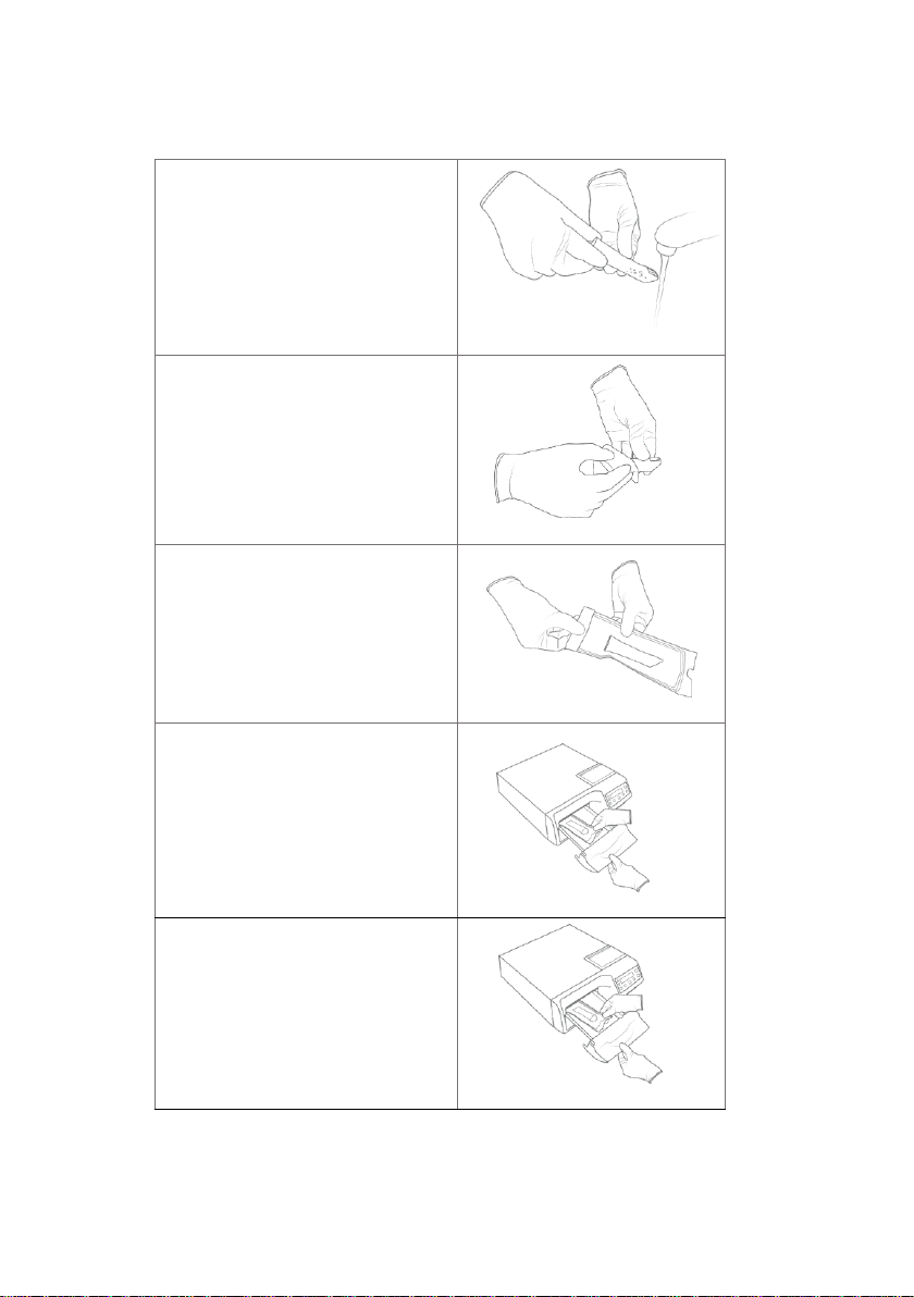
Step-by-Step Procedure
Step 1:
Clean the tip with soapy water,
ensuring that the mirror is clean and
free of smudges, stains, or any residue.
Avoid using abrasive cloth materials as
this will scratch the mirror.
Step 2:
After drying the tip exterior,
carefully dry the interior and mirror
with lint free wipes ensuring you do not
scratch the surface. The mirror should
be free of any noticeable debris or
water spots.
Step 3:
Insert and seal the tip into a
sterilization pouch. Make sure the seal
is airtight. Each tip should be packaged
individually.
Step 4:
Sterilize the wrapped tip in a
steam autoclave at following
parameters:
• 132°C (270°F) at 4 minutes, or
• 134°C (273°F) at 4 minutes
Step 5
: Ensure the dry cycle is
complete prior to removing the tip
from the autoclave. If the pouch is
damp with moisture, proper
sterilization cannot be guaranteed.
Page 31
30
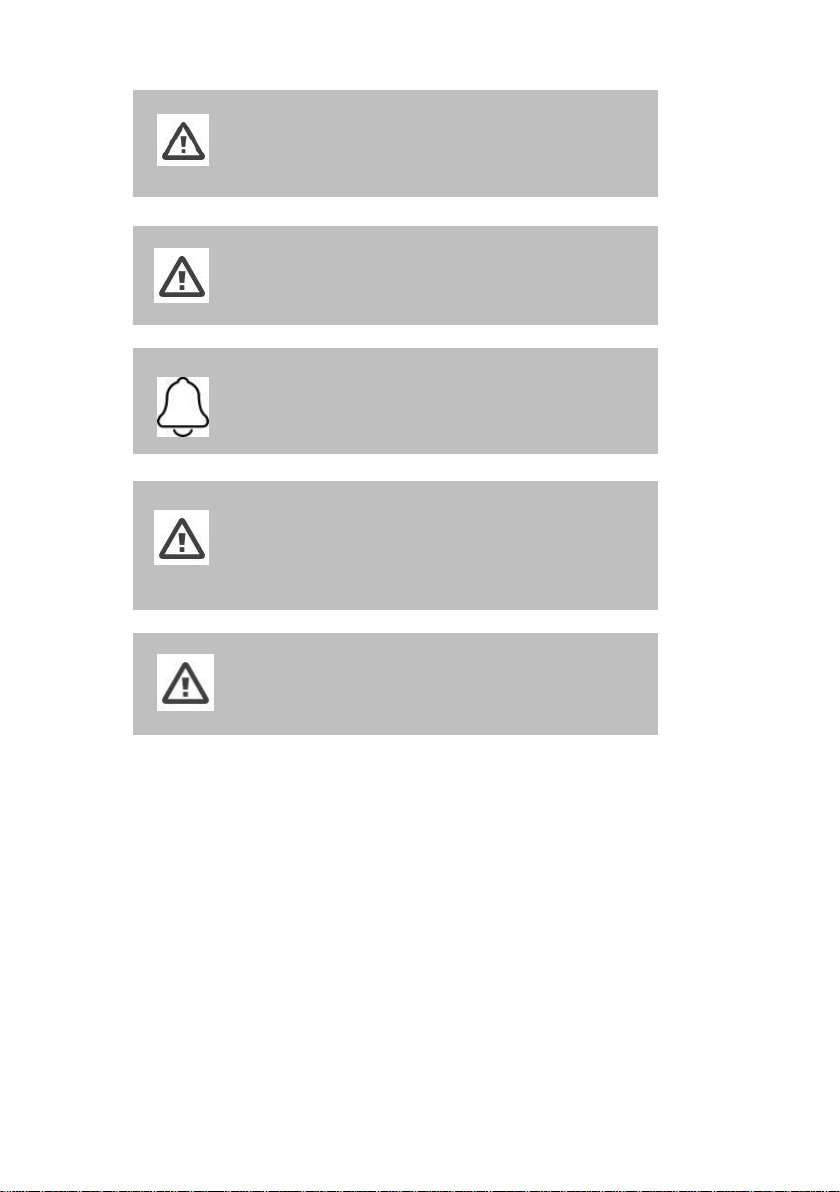
WARNING:
Always autoclave the tip wrapped in a sealed
sterilization pouch; failure to do so will result in permanent stains
on the mirror.
WARNING:
Do not autoclave the handpiece of the device.
NOTE:
Tips should not be placed in an ultrasonic cleaner or any
cold sterile solutions. The sterilant solutions will leave a sticky
residue or film on the mirror when drying.
WARNING:
Do not remove the pouch before the sterilizer
completes its full dry cycle. If the pouch is wet or has any signs of
moisture, this can potentially leave water spots on the mirror
which can affect image quality during scanning.
WARNING:
Use extreme caution when cleaning the mirror as it is
very delicate and is prone to scratching.
7.3 Disposal
The Heron is an electrical device with electronical components inside
and should be disposed of in accordance with local environmental
laws and regulations.
7.4 Calibration
The Heron™ IOS is calibrated in the factory and therefore does not
require calibration when installed.
Page 32

WARNING:
General prohibition indication. The functionality of the
system can be destroyed in the case of incorrect use. If
unauthorized changes have been made to the delivered system
and accessories, the warranty by 3DISC becomes void. 3DISC will
not accept any responsibility or liability for the improper
functioning of the product in such a case.
If the Heron™ IOS begins to have problems scanning and recognizing
teeth models, the system should be examined, which may result in the
system being returned for repair/calibration. See Section 8.4 for further
info.
Page 33
32
8. Safety Guidelines and Warnings
8.1 Warnings and Symbols
NOTE:
Notes represent information that is important to know
but which do not affect the functionality of the system.
WARNING:
The functionality of the system will be limited in the
case of incorrect use.
8.2 General Guidelines
• Do not spill liquids on the body of the device, and never operate
the device in a wet environment.
• Keep the device away from radiators and heat sources.
• Use the device only with the accessories supplied.
• Do not alter the device or open enclosures.
WARNING:
General prohibition indication. The functionality of
the system can be destroyed in the case of incorrect use. If
unauthorized changes have been made to delivered system
and accessories, the warranty by 3D Imaging and Simulation
Corp. Americas becomes void. 3D Imaging and Simulation
Corp. Americas will not accept any responsibility or liability for
the improper functioning of the product in such a case.
If any of the following conditions occur, unplug the device from the
electrical outlet and contact authorized service personnel:
• The power cord or power adapter is damaged.
• The device has been exposed to water.
• The device has been damaged.
• The device does not operate correctly when the operating
instructions are followed.
Page 34
8.3 General Warnings
8.3.1 System Modification
WARNING:
Modifying the system may result in physical injury to
the
patient and operator, and damage to the system.
8.3.2 Approved Software
The Heron™ IOS device is designed to operate with the QuantorClinic™
software. See section 4 for details.
8.3.3 Equipment Failure
WARNING:
In case of system malfunction or failure, you should:
Prevent any contact between the system and the patient.
Unplug the system from the power outlet and the computer.
Store the system away so it cannot be used by someone else.
Contact service personal.
8.4 Mechanical Hazards
8.4.1 Moving Parts
NOTE:
All moving parts are inside handheld scanner so do not
open the unit.
WARNING:
The Heron™ IOS scanner should only be used with
approved, compatible software.
Page 35
34
8.4.2 Dropped Equipment
8.4.3 Base
NOTE:
When not in use, always rest the handpiece on the Base Do
not place the Base on a slanted surface. Place the cables (power
cable and USB cable) where people cannot accidentally get
caught in them and potentially damage the system.
8.5 Electrical Safety
8.5.1 Electrical Shock
WARNING:
There is a risk of electrical shock when opening or
attempting to open any part of the system; only qualified service
personal should open parts of the system.
8.5.2 Stress on Cables
WARNING:
Care should be taken not to apply unnecessary stress
on the cables of the system, whether it is the power cable, the
USB cable or the cable between the handpiece and the Base.
WARNING:
Only use the power adapter supplied as a part of the
system.
WARNING:
If the scanner tip is dropped, ensure that the mirror is
not damaged and that it is not detached; if the tip is damaged it
should be disposed of immediately.
If the scanner handpiece is dropped or bumped, ensure that no
part of the system is damaged as it could affect performance.
Page 36
8.6 Eye Safety
WARNING:
During operation, the system emits a bright, flashing
light from its tip. Although the system complies with standard
IEC 62471 (Photobiological safety of lamps and lamp systems),
prolonged exposure to flashing light may result in discomfort,
seizure or eye irritation.
8.7 Hygiene
WARNING:
In order to maintain safety for the patient, wear
surgical gloves when handling any parts of the system.
Always ensure that the tip is mounted on the handpiece before
inserting it into the mouth of the patient. Before using the
system with a new patient, ensure that the system is disinfected,
and the tip is sterilized.
8.8 During Systems Operation
WARNING:
The Heron™ IOS system contains delicate optical and
mechanical elements and therefore should be handled
carefully. Do not drop, bump, or shake the handpiece or the tip.
Always place the handpiece on the Base when not in use. Do not
put stress on the cable connecting the handpiece to the Base.
Do not submerge the handpiece or the Base in any liquid. Do
not place the handpiece or the Base on wet or heated surfaces.
Hold the handpiece with a firm grip when handling it.
NOTE:
During operation of the system, the handpiece and the
tip may get slightly warm; this is normal.
WARNING:
In order to prevent over-heating of the system, the
ventilation opening at the bottom of the handpiece should
never be obstructed.
Page 37
36
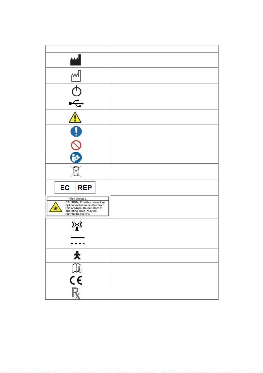
8.9 Symbols on the Heron and Transport Case
Symbol
Description
Manufacturer’s trade name and address (ISO
15223-1)
Date of manufacture (ISO 15223-1)
Equipment Power On/Off (push/push)
USB plug
Warning, Consult Accompanying Documents
General mandatory action manual
General prohibition indication
User Manual Reference
Directive on Waste Electrical and Electronic
Equipment
Authorized Representative in the European
Community
Warning label for LED
Non-ionizing electromagnetic radiation
Direct Current
Type(B) Level of protection against electric shock
Consult operating instruction for use.
European Conformity mark
Prescription symbol
Page 38

9. Support, Warranty and Repair Service
9.1 Support
If you have questions about the software, please consult the manual
and Help menu in the software. If you are experiencing issues with your
software, please check the list of common issues provided in section
8.6 prior to contacting a dealer. It could be simply a question of a
minor issue that can be fixed quickly. However, if you’re still
experiencing problems after following the recommendations in this
section, then please contact the dealer where you bought the
equipment.
9.2 Standard Warranty
3DISC warrants its non-consumable hardware products to be free from
defects in materials and workmanship. The warranty covers the cost of
parts and labor to repair the product.
Please keep the shipping container for future use. Products returned to
the factory for repair should be properly packaged. To obtain warranty
service, follow the procedure described in the Repair Service section.
Failure to do so will cause delays and additional expense to the
customer.
The warranty is valid when the product is used for its intended purpose
and does not cover products which have been modified without
written permission from 3D Imaging and Simulation Corp. Americas, or
which have been damaged by abuse, accident or connection to
incompatible equipment.
This warranty is in lieu of all other warranties, expressed or implied.
9.3 Repair Service
The Heron™ IOS cannot be serviced locally. In the event of a hardware
malfunction, contact your dealer to arrange for a swap unit (same
model or newer) so your unit can be replaced, and work can continue.
Some testing might be needed in order to verify the
Hardware/Software error or malfunction.
The company reserves the right to cease providing repair,
maintenance, parts and technical support for its non-consumable
hardware products five years after a product is discontinued. Technical
support for old versions of software products will cease 12 months
after they are upgraded or discontinued.
Page 39

38
9.4 Out of Warranty Repair Service
Out of warranty repair service is available in selected geographical
locations. Contact the supplier for current terms and rates.
9.5 Troubleshooting Guide
Issue Recommendation
The software won’t start. It shows a
License/Dongle error.
Check that the USB license dongles
are attached to the PC.
The dentalshare window is blank.
You must have a Lab connected to
your Dentalshare account for
information to appear here.
There’s a memory full error message
that pops up when the software is
open.
Clear some space on the C Drive
The status in the Live view window is
“Disconnected”.
Check that you have external power to
the Heron and that the USB cable is
connected to a USB 3 Port.
Scanning is very slow.
Check that the Laptop is connected to
an external power source.
The corners are cut in the live view
window.
Check that the Tip is correctly
mounted and when rotating it is
locking in place with a click.
There is a globe in the scan window
and “Global lock on” is shown.
Go back to a tooth that is scanned and
start from there again
No images appear when scanned but
everything else (e.g. live window image,
sounds, FPS) works fine.
The scanner might need to be
recalibrated. Please contact your local
dealer for support.
There are spots on the Live view
window.
Check and clean the mirror of the tip.
Where can I get the Heron™ IOS
software and manuals?
Please find them in the Support
section of 3DISC website.
Page 40

We hope this User Manual was helpful to you.
For additional material and user information go to
3disc.com/support.
Heron IOS Quick Guide
Heron IOS How-to Vidoes
Heron IOS Training Videos
3disc.com/support
Page 41
40
Why 3DISC Dental Solutions?
3DISC is an American manufacturer of digital imaging solutions.
Dental clinics can rely on the fact that 3DISC, with its expertise
and continuous product development, will work to secure their
investments through a product philosophy based on innovation
and reliability. The development of our solutions begins and ends
with the dentist and patient in mind and our aim is to make
affordable quality imaging solutions for dental practices.
www.3DISC.com
USA & Canada
Europe, Middle East &
Africa
Asia Pacific & Australia
3D Imaging and Simulation
Corp. Americas
365 Herndon Pkwy #18
Herndon, VA 20170
United States
Tel: +1 703 430 6080
Tel: +1 800 670 0363 (Toll free)
Contact 3DISC
Contact support
3DISC Europe
Gydevang 39-41
3450 Alleroed
Denmark
Tel: +45 88 276 650
3DISC Asia
#912, 165, Magokjungang-ro
Gangseo-gu, Seul
Rep of Korea
Tel: +82 2 6101 3110
IOS-FPM-71-001_EN_OCT19
 Loading...