

Page 1

LFP Handhe ld Rev1.0
Product Manual
Page 2

Product Manual
Customer Documentation
Version 1.0
LFP Handhe ld Ke yb oar demul ati on 07.06.2018
Page 2 of 75
0. Table of Contents
0. Table of Contents 2
1. Introduction 4
1.1 Using the Device 5
2. Version History 6
3. Abbreviations and Designations Used 6
4. General Instructions 7
4.1 Objective of th e Produ ct Manu al 7
4.2 Warranty and Liabi lity 7
5. Safety Instructions and Warnings 8
5.1 Scope and Symbols 8
5.2 Safety S ymb ols - According to DIN 4844-2 8
5.2.1 Mandatory Signs 9
5.2.2 Warning Signs 9
5.2.3 Prohibition Signs 9
5.2.4 Other S igns 10
5.3 Obligations 10
5.3.1 Operator´s Obligations 10
5.3.2 Responsibilities of Operating Personnel 11
5.3.3 ESD Ins truc tion s 11
5.3.4 Residual Risks 12
5.3.5 Supplemental Instructions 13
5.3.6 Regulations and Certifications 14
6. Functional Descri p tion 14
6.1 Functionality 14
6.1.1 General Inf orm at io n 14
6.1.2 Normal Operation 14
6.1.3 Polling Mode 14
6.2 Illustration 15
6.2.1 Membrane Keypad 15
6.2.2 Rear View 15
Description of the Comp onen ts 16
6.3 Technical Data 17
6.3.1 Device Label 17
6.3.2 Device Label FCC ID 2AP5OLFP 18
7. Installation 19
7.1 Safety I nstructions 19
7.2 Qualif ied I nst al lat io n Per so nn el 20
7.3 Unpacking 20
7.4 Power Supply 20
7.5 Dimensions 21
7.6 Connecting the LFP Reader 21
7.6.1 LFP Reader Operating Mode Keyboard Emulation 21
7.6.2 LFP Reader Operating Mode ASCII Protocol 21
HERMOS AG
Gartenstra s se 19 Tel. +49(9279) 991-0
D-95490 M istelgau Fax. +49(9279) 991-100
Page 3

Product Manual
Customer Documentation
Version 1.0
LFP Handhe ld Ke yb oar demul ati on 07.06.2018
Page 3 of 75
8. Operation 23
8.1 Operating Personnel 23
8.2 Setting the Operating Mode 23
8.3 Operating Mode K eyboard Emu lation 23
8.3.1 Setup Mode 23
8.3.2 Parameters 24
8.3.3 State Diagram Operating Modes 31
8.3.4 Proces s Dia gram 32
8.3.5 ASCII - Table 33
8.3.6 Control and Function Symbols 36
8.4 ASCII Protocol Op erating M ode 37
8.4.1 Struct ure of the C omm un icat ion Pr ot oco l 37
8.4.2 Packet Content 37
8.4.3 Data Elements 39
8.4.4 Protoc ol Com man ds 42
8.4.5 Parameters 61
8.4.6 Message Examples 68
8.4.7 Error Codes 70
9. Service and Troubleshooting 72
9.1 General Infor mation 72
9.2 Troubleshooting Personne l 72
9.3 Safety I nst ruct ion s 73
9.4 Software Releases 74
9.5 Customer Service 74
10. Disassembly and Storage 75
10.1 Disassembly 75
10.2 Storage 75
11. Transport and Disposal 75
11.1 Transport 75
11.2 Disposal 75
HERMOS AG
Gartenstra s se 19 Tel. +49(9279) 991-0
D-95490 M istelgau Fax. +49(9279) 991-100
Page 4
Product Manual
Customer Documentation
Version 1.0
LFP Handhe ld Ke yb oar demul ati on 07.06.2018
Page 4 of 75
1. Introduction
The device complies with the guideline "R adio Equipment Directive 2014/53/EU (RED)" of
the European Parliament and the Council on rad io equip m ent and te le com munications terminal
These operating instructions are addr e sse d to the opera tor , who m ust pass them over to the
personnel responsible for installation, c onnection, use and repairs of the device.
The operator has to ensure that the information given in the instr uc tion manuals and in the
The instruction manuals have to be held in a known and easily accessible place and must be
The manufacturer assumes no responsibility for damage to persons, animals, property or the
device itself caused by improper use, non-compliance with or insufficient observance of the
safety criteria contained in these ins truction manual or by modification of the device or the use
equipment and the mutual recognition of co nform ity .
enclosed documents have been read and understoo d .
consulted even in the slightest doubt.
of unsuitable spare parts.
The copyright for the instruction manual lies solely with
HERMOS AG
Reproduction or circulation of this do c ument to third par tie s only by expre s s writte n p er mission
HERMOS AG
Gartenstra s se 19 Tel. +49(9279) 991-0
D-95490 M istelgau Fax. +49(9279) 991-100
of copyright holder. This also applies if only ex cerp ts of the doc ument ar e cop ied or circulated.
These same conditions apply to the disclosur e of the doc ument in digital format.
Track & Trace - RFID Division
Gartenstr.19
95490 Mistelgau
or its legal successor.
As of: September – 2017
Page 5

Product Manual
Customer Documentation
Version 1.0
LFP Handhe ld Ke yb oar demul ati on 07.06.2018
Page 5 of 75
1.1 Using the Device
The device is used exclusively to read passive LF transponders.
Any other use of the device or any use beyond its intended purpose is considered non-intended and
thus improper.
In this case, the device safety and the device protection provided may be compromised. HERMOS AG
is not liable for damages resulting from such use.
The device has been developed for use in an industrial environment as a built-in device for other
systems. It has not been developed as a stand-alone or mobile device in a non-industrial environment,
such as domestic, vehicle or open air use.
Intended use also includes the following:
• Following all the oper ating instructions
• Following all the saf ety instruc tions
Improper use which can endanger the operator, third parties or the device include:
• The use of the device contrary to its intended purpose
• Modificatio ns to the dev ice as well as attachments and conversions
• Operating th e device when there are obviou s pr oblems
WARNING
Risk of injury due to unauthorized modifications
Dangers exist due to unauthorised modifications to the device.
Only original spare parts from the manufacturer may be used. No modifications,
attachments or conversions may be made to the device without the permission of
HERMOS AG.
WARNING
Risk of injury and malfunction due to improper use
Dangers exist due to improper use of the device.
The device must only be used in accordance with its intended purpose.
HERMOS AG
Gartenstra s se 19 Tel. +49(9279) 991-0
D-95490 M istelgau Fax. +49(9279) 991-100
Page 6

Product Manual
HERMOS AG
RK
Initial vers i on of
customer documentation
Radio Frequeny Identification
LF
Low Frequency 134,2 kHz
USB
Universal serial bus, bus syst em f or computers
Customer Documentation
Version 1.0
LFP Handhe ld Ke yb oar demul ati on 07.06.2018
Page 6 of 75
2. Version History
Version Date Author Amendments
1.0 07.06.2018
3. Abbreviations and Designations Used
RFID
HERMOS AG
Gartenstra s se 19 Tel. +49(9279) 991-0
D-95490 M istelgau Fax. +49(9279) 991-100
Page 7

Product Manual
Customer Documentation
Version 1.0
LFP Handhe ld Ke yb oar demul ati on 07.06.2018
Page 7 of 75
4. General Instructions
All previous editions of this document are no longer valid with the issue of this version.
The information in this document is compiled to the best of our knowledge and belief. HERMOS AG
does not guarantee the accuracy and completeness of the information provided in this document and
is also not liable for consequential damages due to incorrect or incomplete information.
4.1 Objective of the Product Manual
The product manual serves as support and contains all necessary information which must be observed
for general safety, transport, installation and operation.
The product manual with all safety instructions (as well as all additional documents) has to be:
• Followed, read and understood by all persons working with the device
(in particular, knowledge of the safety instructions)
• Open to the public
• Consulted in the slightest doubt (secur i t y)
Objectives:
• Prevent accidents
• Increase service life and reliability of the device
• Reduce the costs of production downtime
4.2 Warranty and Liability
The "General Terms and Conditions of Sale and Delivery" of HERMOS AG apply.
The warranty period is 12 months beginning with the delivery of the device, which is verified by the
invoice or other documents.
The warranty includes repairs of all damage to the device that occurs during the warranty period
and is clearly caused by m ater ial or manufacturing defects.
Warranty and liability claims in the event of personal injury or property damage are excluded if they
are attributable to one or more of the following causes:
• Improper use of the device
• Non-observance of the information in the operating instructions
• Unauthorised structural modifications to the device
• Inadequate repair and maintenance measures
• Disaster events due to impact with foreign objects or force majeure
HERMOS AG
Gartenstra s se 19 Tel. +49(9279) 991-0
D-95490 M istelgau Fax. +49(9279) 991-100
Page 8

Product Manual
Customer Documentation
Version 1.0
LFP Handhe ld Ke yb oar demul ati on 07.06.2018
Page 8 of 75
5. Safety Instructions and Warnings
5.1 Scope and Symbols
Follow the general safety instructions as well as the speci al saf et y instr uct ions inc lude d in the chapters.
The device is built according to the latest state of the art technology and recognized safety regulations.
To avoid danger to life and limb of the operator, third parties or the device when using it, use the device
exclusively for its intended purpose and in perfect condition with regard to safety.
Bodily injuries and/or property damages resulting from non-compliance with the instructions provided
in the operating instructions are the responsibility of the company operating the device or the
assigned personnel.
Faults that may compromise safety must be eliminated immediately.
DANGER
Risk of death, injury and property damage
There is a risk of danger due to disregard of the product manual and the
safety
information contained therein.
Read the product manual carefully before initial operation.
Fulfil all required safety conditions.
5.2 Safety Symbols - According to DIN 4844-2
The following special safety symbols in accordance with DIN 4844-2 are used at the corresponding
passages in the text of this product manual and require special attention depending on the combination
of the signal word and symbol.
WARNING
Risk of injury due to disregarding the safety symbols.
Risks exist when disregarding warnings in the operating instructions.
Follow all warnings.
HERMOS AG
Gartenstra s se 19 Tel. +49(9279) 991-0
D-95490 M istelgau Fax. +49(9279) 991-100
Page 9
Product Manual
Customer Documentation
Version 1.0
LFP Handhe ld Ke yb oar demul ati on 07.06.2018
Page 9 of 75
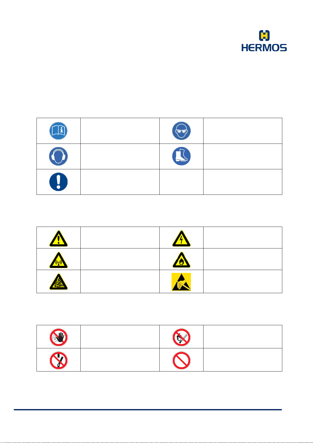
5.2.1 Mandatory Signs
5.2.2 Warning Signs
5.2.3 Prohibition Signs
Observe addi tio nal in fo rmati on
Wear ear pr otec tion
Important note
Warning of a hazardou s area
Warning of electromagnetic
radiation
Warning of explosive
substances
Use safety goggles
Wear safet y shoes
Warning of hazardous
electrical voltage
Warning of flammable
substances
Warning of electrost at ic ally
sensitive components
Unauthorised acc e ss is
prohibited
Switching prohibited
Fire, open flame and smoking
prohibited
Prohibition
HERMOS AG
Gartenstra s se 19 Tel. +49(9279) 991-0
D-95490 M istelgau Fax. +49(9279) 991-100
Page 10

Product Manual
Customer Documentation
Version 1.0
LFP Handhe ld Ke yb oar demul ati on 07.06.2018
Page 10 of 75
5.2.4 Other Signs
Dispose of packaging material
according to regulations
5.3 Obligations
5.3.1 Operator´s Obligations
A safety-related condition and use of the device is a requirement for safe operation of the device.
Theref ore, the o per ator has the obligation to ensure that the following points are observed:
The device may only be operated by trained and authorised
personnel!
Have personnel who must be trained, instructed or within
the scope of general training work only on the device under
the supervision of an experienced person!
Have the personnel confirm by their signature that the
operating instructions have been understood!
Precisely establish responsibilities according to the various
task areas (operation, installation)!
Recycling
Operating personnel must be required to immediately
report any occuring and identifiable safety deficiencies to
their superior!
HERMOS AG
Gartenstra s se 19 Tel. +49(9279) 991-0
D-95490 M istelgau Fax. +49(9279) 991-100
Page 11

Product Manual
Customer Documentation
Version 1.0
LFP Handhe ld Ke yb oar demul ati on 07.06.2018
Page 11 of 75
5.3.2 Responsibilities of Operating Personnel
The operating personnel is obligated to contribute to the prevention of work accidents and
their consequences by their personal conduct.
WARNING
5.3.3 ESD Instructions
CAUTION
Risk of injury due to in sufficient pe rsonnel qualificati ons
There are dangers to personnel and the proper operation due to
inadequately qualified personnel.
Only trained personnel may operate the unit.
New operating personnel must be instructed by the existing operating
personnel.
The operator must regulate the personnel’s areas of responsibility,
competence, and monitoring precisely.
The personnel for the areas of responsibility mentioned above must have the
corresponding qualification for this work (training, instruction).
If necessary, this can be done by the manufacturer on behalf of the operator.
In case of disregard, all warranty claims are void.
Static electricity can damage electronic components in the device. All
persons who install or maintain the device must be trained in ESD protection.
ESD pro t ect iv e m eas ur es m u st b e taken when opening the unit.
Disconnect the power supply before removing or adding components!
Observe the basic principles of ESD protection
Take the appropriate ESD precautionary measures
HERMOS AG
Gartenstra s se 19 Tel. +49(9279) 991-0
D-95490 M istelgau Fax. +49(9279) 991-100
Page 12

Product Manual
Regularly check the electrical equipment of the unit. Regularly check all
Customer Documentation
Version 1.0
LFP Handhe ld Ke yb oar demul ati on 07.06.2018
Page 12 of 75
5.3.4 Residual Risks
Despite all precautionary measures taken, there may still be residual risks that are not
apparent.
Adhering to the safety instructions, the intended use, and the product manual as a whole can
reduce residual risks.
DANGER
ATTENTION
DANGER
Danger Caused by Electrical Current
Electrical residual energy remains in lines, equipment and devices after
shuttingdown the device.
Only qualified electricians may perform work on the electrical supply
system.
Disconnect the unit from the power supply system if active parts of the
unit can be accessed using tools. Access is only permitted by
authorised personnel.
moving cables for damage within the scope of maintenance and repair
work.
Dangers of F ire a nd Explos ion
There is a risk of fire and explosions in the vicinity of the device.
Smoking, exposed flames and fire are strictly prohibited in the vicinity of
the unit. Do not store any flammable liquids within the hazardous area of
the device.
A fire extinguisher must be kept in the vicinity of the device.
Warning of Electrom agneti c Radiation
WARNING
Electromagnetic radiation is generated when data is transmitted and
received.
Position the antenna so that it is not in the vicinity of the human body or
HERMOS AG
Gartenstra s se 19 Tel. +49(9279) 991-0
D-95490 M istelgau Fax. +49(9279) 991-100
touches it during transmission.
The device complies with EN50364:2010 (Human Exposure).
Page 13

Product Manual
Customer Documentation
Version 1.0
LFP Handhe ld Ke yb oar demul ati on 07.06.2018
Page 13 of 75
5.3.5 Supplemental Instructions
Read and understand all safety and operating instruc tions b efore
installing and operating the device.
This documentation was written for specifically trained personnel. The
installation, operation and error handling may only be carried out by
specifically trained personnel.
Keep these instructions. Keep this documentation in a location that is
accessible to all personnel involved into the installation, use and error
handling of the device.
Follow all warnings. Follow all warnings given on and in the device as
well as in the docume ntation.
Install the device only in accordance with the manufacturer´s
instructions.
Use only the accessories and cables from the manufacturer.
Troubleshooting that is not described in this docume ntation may only be
performed by the manufacturer.
When plugging cable connections, only pull on the plug and not on the
cable.
Never overbend antenna cables or subject them to mechanical forces.
Only use spare parts specified by the manufacturer.
The provisions of the accident-prevention regulations of the government safety organisations
always apply to all work on the device.
Applicable, legally binding accident prevention regulations
Applicable binding regulations at the place of use
Technical standards for safety and professional work
Existing environmental protection regulat ion s
Other applicable regulations
HERMOS AG
Gartenstra s se 19 Tel. +49(9279) 991-0
D-95490 M istelgau Fax. +49(9279) 991-100
Page 14

Product Manual
Customer Documentation
Version 1.0
LFP Handhe ld Ke yb oar demul ati on 07.06.2018
Page 14 of 75
5.3.6 Regulations and Certifications
The electrical design and documentation comply with the DIN / VDE, EN / IEC regulations.
Functional Description
5.4 Functionality
5.4.1 General Information
The LFP Handheld Reader USB is a radio frequency identification system that uses radio transmission
to read or write data from LF transponders (134.2 kHz).
The core piece is an LF transponder (134.2 kHz) which operates as a forgery-proof electronic tag.
The reading unit of the system transmits an energy pulse via the antenna. The transponder is supplied
with energy by this pulse. The transponder then sends the stored data back to the device.
The reading process takes approx. 100ms (communication between transponder and device).
Since a line of sight between the device and transponder is not absolutely necessary, the transponder
can also be identified through non-metallic material.
The LF Handheld Reader USB reads all 134.2kHz transponders according to ISO18000-2 (and
ISO11785) common on the market.
5.4.2 Normal Operation
During normal operation, the LFP handheld reader is immediately ready for operation after a reset.
It does not perform any independent actions in this mode.
Pressing the read button triggers an automatic reading and, if the reading is successful, the data of the LF
tag are output.
5.4.3 Polling Mode
The reader can be set to a state of continuous reading, the so-called polling mode. The device then
performs a readout at regular intervals and outputs the data of the read LF transponder.
HERMOS AG
Gartenstra s se 19 Tel. +49(9279) 991-0
D-95490 M istelgau Fax. +49(9279) 991-100
Page 15
Product Manual
Customer Documentation
Version 1.0
LFP Handhe ld Ke yb oar demul ati on 07.06.2018
Page 15 of 75
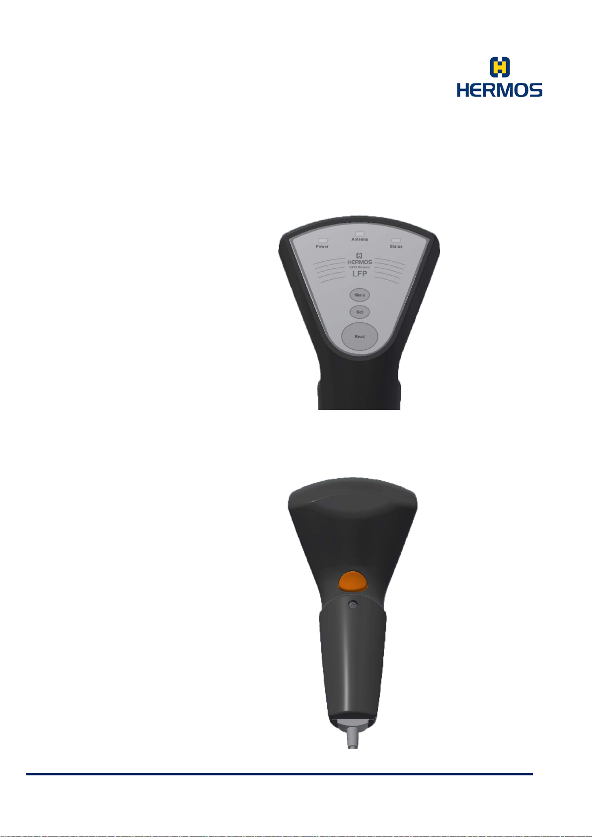
5.5 Illustration
5.5.1 Membrane Keypad
1. Power LED
2. Antenna LED
3. Status LED
4. Menu Button
5. Set Button
6. Read Button (1)
5.5.2 Rear View
1. Read Button (2)
2. USB Connection Cable
HERMOS AG
Gartenstra s se 19 Tel. +49(9279) 991-0
D-95490 M istelgau Fax. +49(9279) 991-100
Page 16

Product Manual
The status LED indicates a successful reading process. In ASCII
Customer Documentation
Version 1.0
LFP Handhe ld Ke yb oar demul ati on 07.06.2018
Page 16 of 75
Description of the Components
Component Description
Power LED
Antenna LED
Status LED
Menu Button
Set Button
Read Button (1)
The power LED illuminates when the reader is plugged into a USB
port and indicates operation readiness.
The antenna LED indicates the execution of an RF ID r ead o r wri te
process.
protocol mode, this behaviour can be activated or deactivated via
parameters.
Use the menu button to switch the LFP handheld reader to a setup
mode to configure the settings.
The set button is used to select parameters in the menu and to
transfer parameter settings.
The read button triggers an automatic reading.
The execution of the reading is indicated by the antenna LED, the
result of the reading is indicated by the status LED.
In setup mode, the read button (1) is used to configure the
parameters. The function is identical to read button (2).
USB
Connection Cable
Read Button (2)
Antenna
The USB connection cable is fixed to the LFP handheld reader.
The length of the connection cable is adjustable.
The function is identical to read button (1).
With the integrated antenna, ranges of up to 100mm are possible,
depending on the transponder type.
An internal signal buzzer is provided for acoustic indication of
Signal Buzzer
readings. In both operating modes the buzzer can be activated or
deactivated via parameters.
HERMOS AG
Gartenstra s se 19 Tel. +49(9279) 991-0
D-95490 M istelgau Fax. +49(9279) 991-100
Page 17

Product Manual
Permissible humidity at
50°C
HERMOS AG
Customer Documentation
Version 1.0
LFP Handhe ld Ke yb oar demul ati on 07.06.2018
Page 17 of 75
5.6 Technical Data
Technical Data
Connection USB, variable cable length (max. 3m)
Operat in g T em per a tur e -25 °C bis 50 °C
Storage Temperature -40 °C bis 85 °C
25 – 80 %
Transmission Frequency 134,2 kHz , ISO18000-2
Reading Range Type 100mm, with 32mm glass transponder
Protection IP 40
Housing Material ABS
Dimensions approx. 185 x 90 x 60 mm
Voltage 5 V (+/ - 5%)
Power Consumption Type 80mA / 300mA ( pass ive / active )
Protocol ASCII, Hex, Keyboard Emulation
5.6.1 Device Label
The device label is located on the LFP reading device housing.
It contains a CE mark as well as an article and serial number.
1. Designation
2. Articel Number (Variants)
3. Serial Number (Example)
4. MAC address
5. Manufacturer
LFP USB Handheld Reader CE
P/N: HRF.R.LFP.0I.YU.10.30A
S/N: 1701HAG00123
HKxxxxxx
HERMOS AG
Gartenstra s se 19 Tel. +49(9279) 991-0
D-95490 M istelgau Fax. +49(9279) 991-100
Page 18

Product Manual
This device complies with Part 15 of the
Customer Documentation
Version 1.0
LFP Handhe ld Ke yb oar demul ati on 07.06.2018
Page 18 of 75
5.6.2 Device Label FCC ID 2AP5OLFP
FCC
- The Federal Communications Commission (FCC) warns the users that changes or modifications to
the unit not expressly approved by the party responsible for compliance could void the user's
authority to operate the equipment.
RF exposure statement portable devices)
This device complies with the RF exposure SAR test exclusion requirements for portable devices, if a
minimum separation distance 50mm is kept. However, the device shall be used in such a manner that
the potential for human contact during normal operation is minimized.
- FCC §15.105 (b):
NOTE: This equipment has been tested and found to comply with the limits for a Class A digital
device, pursuant to part 15 of the FCC Rules. These limits are designed to provide reasonable
protection against harmful interference when the equipment is operated in a commercial environment.
This equipment generates, uses, and can radiate radio frequency energy and, if not installed and
used in accordance with the instruction manual, may cause harmful interference to radio
communications. Operation of this equipment in a residential area is likely to cause harmful
interference in which case the user will be required to correct the interference at his own expense.
FCC Rules. Operation is subject to the
following two conditions: (1) this device
may not cause harmful interference, and
(2) this device must accept any
interference received, including
interference that may cause undesired
HERMOS AG
Gartenstra s se 19 Tel. +49(9279) 991-0
D-95490 M istelgau Fax. +49(9279) 991-100
Page 19
Product Manual
The device is exclusively designed for indoor use in an industrial
dity level within the range of the specified technical module parameters.
Never use the unit near or in water.
technician.
Do not install the device near heat sources such as radiators, heat
Do not install the device in a flammable environment.
The device (especially the antenna) should not be installed in the
This could result in reduced read and write ranges.
Customer Documentation
Version 1.0
LFP Handhe ld Ke yb oar demul ati on 07.06.2018
Page 19 of 75
6. Installation
Follow the basic safety instructions in the chapter safety instructions.
6.1 Safety Instructions
environment.
The device may only be installed indoors with a temperat ure a nd hum i-
Never pour liquids of any type over the unit. However, if the unit should
still come in contact with liquid, disconnect it and have it checked by a
registers, stoves or ot her devices (including amplifiers) that generate
heat.
Never expose the device to extreme temperature fluctuations, since
otherwise condensation develops inside the device and causes
damages.
Do not install the device in the vicinity of voltage lines or other power
lines with which they could collide (for example, drilling), which could
result in serious inj uries or e ven d eath .
immediate vicinity of electrical equipment such as medical devices,
monitors, telephones, TV sets and magnetic disks, and metal objects.
Never use the unit in explosive areas (such as paint warehouses).
Do not use the device in areas where it is exposed to vibrations or
shocks.
The installation location must be adequately illuminated during the
installation.
Never install the unit during a lightning storm.
HERMOS AG
Gartenstra s se 19 Tel. +49(9279) 991-0
D-95490 M istelgau Fax. +49(9279) 991-100
Page 20
Product Manual
Customer Documentation
Version 1.0
LFP Handhe ld Ke yb oar demul ati on 07.06.2018
Page 20 of 75
Ensure that the installation meets FCC (country specific) requirements
for human exposure to radio frequencies.
6.2 Qualified Installation Personnel
The unit must only be installed by specially trained personnel. If you have
any doubts about the qualifications, please contact the manufacturer.
If the unit is operated by untrained personnel, the reading device and/ or
connected devices may be damaged.
6.3 Unpacking
The LFP reading device and the accessories can be packed customer-dependent under
clean room conditions. In order to maintain this condition, the devices must be unpacked
under clean room conditions.
6.4 Power Supply
The packaging material consists of cardboard and foil.
Dispose of these materials separately under the respective regulations
of your country.
Danger exists if the device is supplied with the wrong voltage.
Only use cables, plugs and adapters from the manufacturer.
Observe the connection values of the technical data.
HERMOS AG
Gartenstra s se 19 Tel. +49(9279) 991-0
D-95490 M istelgau Fax. +49(9279) 991-100
Page 21
Product Manual
Customer Documentation
Version 1.0
LFP Handhe ld Ke yb oar demul ati on 07.06.2018
Page 21 of 75
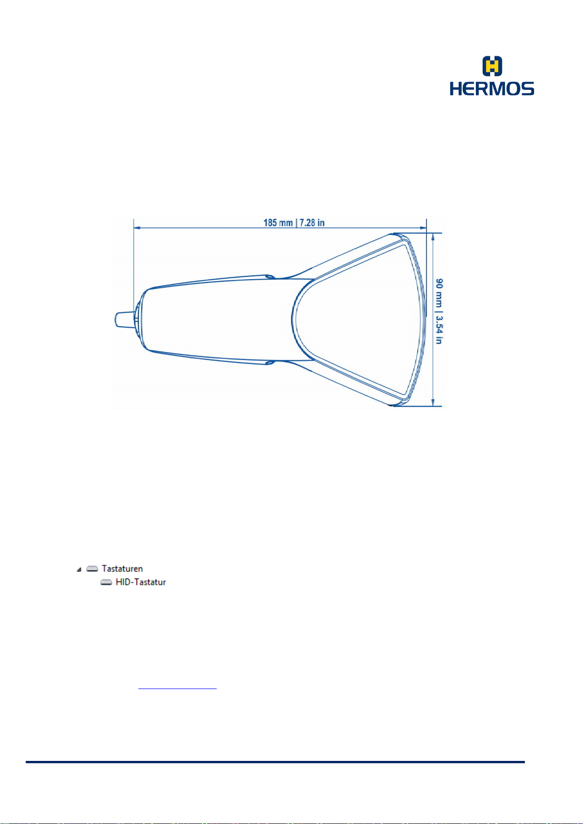
6.5 Dimensions
6.6 Connecting the LFP Reader
6.6.1 LFP Reader Operating Mode Keyboard Emulation
The LFP reader with set keyboard emulation can be connected to any USB port of a running PC. The driver
is automatically detected and installed. After a few seconds the operating system of your computer reports
the successful installation and the reader is ready for operation.
The LFP reader with keyboard emulation works like a connected
keyboard. It is displayed as an additional HID keyboard in the
device manager of your system.
6.6.2 LFP Reader Operating Mode ASCII Protocol
The LFP reader with set ASCII protocol can be connected to any USB port of a running PC. Before
connecting the reader, however, the driver for the virtual COM port must be successfully installed so that
the connected device can be addressed via the virtual COM port. The driver is available in the download
area of the RFID products on the HERMOS homepage.
Homepage: www.hermos.com
User Name: Customer_LF
Password: 781692
After downloading and unpacking the driver, the installation is started by running the application
CP210xVCPInstaller_x64.exe or CP210xVCPInstaller_x86.exe.
HERMOS AG
Gartenstra s se 19 Tel. +49(9279) 991-0
D-95490 M istelgau Fax. +49(9279) 991-100
Page 22
Product Manual
8
1
Customer Documentation
Version 1.0
LFP Handhe ld Ke yb oar demul ati on 07.06.2018
Page 22 of 75
When using a single USB reader, select the "SingleReader" driver. The reader can be operated on any
USB port of the PC.
When using several USB readers simultaneously, select the "MultiReader" driver. A virtual serial port is
assigned to each USB port. A reader can be installed on each USB port of the PC.
The USB reader is now connected to a USB interface of the PC, the computer recognizes the device
and automatically starts the driver installation.
Follow the further installation instructions and install the software via "Install the software automatically".
If the automatic installation fails, start the manual installation.
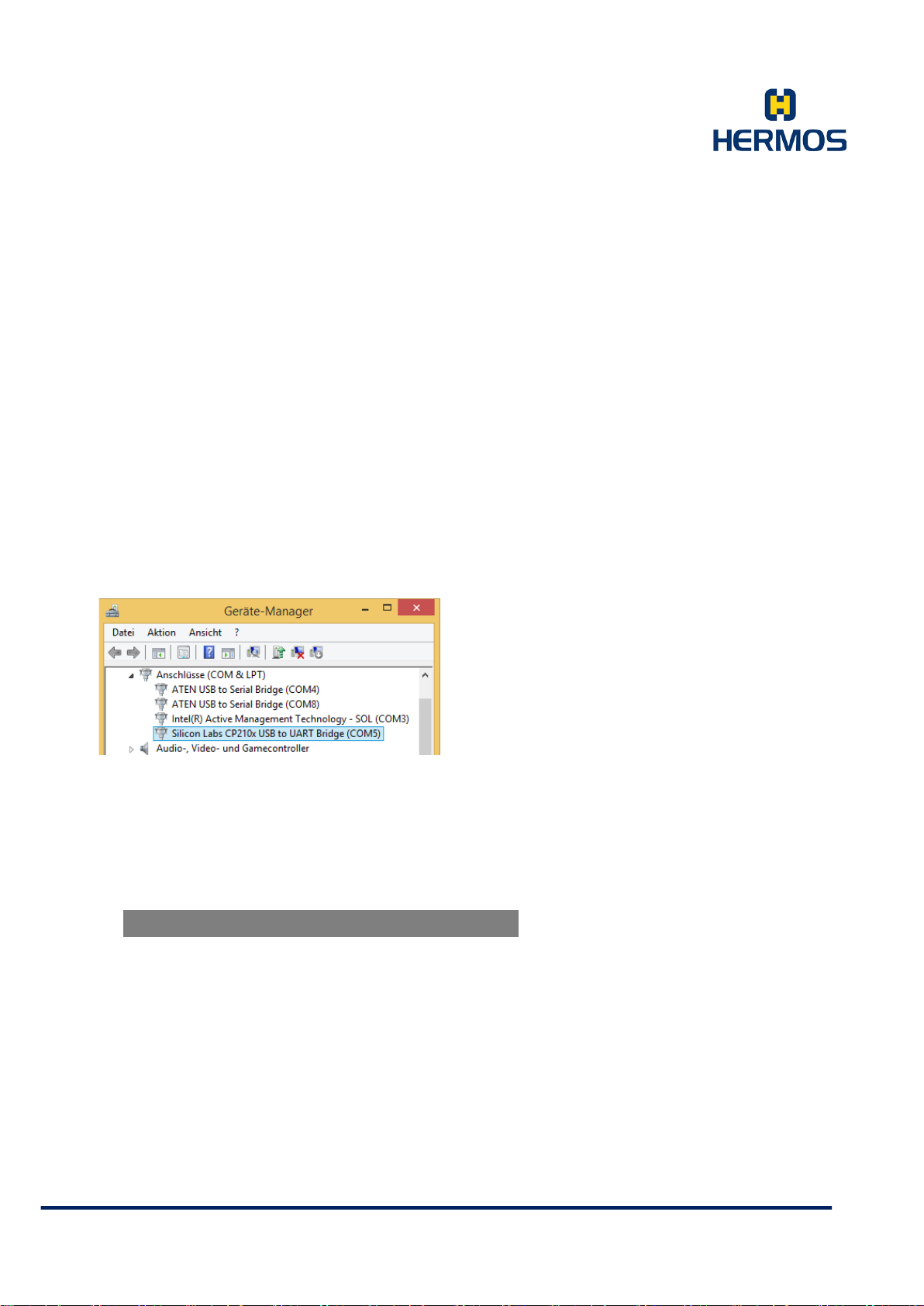
If the driver is successfully installed and the USB reader is plugged in, it can be accessed via the virtual
COM port. In the Device Manager of the Control Panel, the corresponding virtual COM port is displayed as
"Silicon Labs USB to UART Bridge.
6.6.2.1 Parameters of the Serial Interface
Serial communication takes place via a virtual COM port, which has the following unchangeable
communication parameters.
Figure
Baudrate 19200
Data bits
Stop bits
Parity
Even
HERMOS AG
Gartenstra s se 19 Tel. +49(9279) 991-0
D-95490 M istelgau Fax. +49(9279) 991-100
Page 23
Product Manual
The device should only be operated by specially trained personnel. If
damage to the device or connected devices.
Customer Documentation
Version 1.0
LFP Handhe ld Ke yb oar demul ati on 07.06.2018
Page 23 of 75
7. Operation
7.1 Operating Personnel
you are in doubt about the required qualification, please contact the
7.2 Setting the Operating Mode
The LFP reader has 2 different operating modes:
- Keyboard emulation analog keypad
- ASCII protocol communication via virtual COM port
Switch between the two operating modes via the connected membrane keypad:
Press and hold the "Read" key on the membrane keypad
Press the "Menu" key on the membrane keypad and hold it together with the "Read" key for about 10
seconds until all LEDs and the buzzer light up
When the two keys are released, the operating mode is changed and the device is restarted
manufacturer.
Operation of the device without the specific expertise can lead to
7.3 Operating Mode Keyboard Emulation
If the device is plugged in or restarted, the Keyboard Emulation operating mode is indicated by the
following combination of LEDs and signal buzzer:
- The antenna LED, the status LED and the buzzer are briefly switched on and off again
(test of the membrane keypad)
- Short waiting time
- The antenna LED, the status LED and the buzzer are briefly switched on and off twice in succession
The LFP reader USB works like a connected keyboard. To read a transponder, place the cursor in a text
document or in a text input field of the active application. Hold the device near a transponder and press the
read button.
An active reading is indicated by the antenna LED lighting up.
The LFP reader reads the transponder and writes the read data via the USB interface into the text
document or input field.
The data format (ASCII or HEX) can be adjusted in the setup mode.
7.3.1 Setup Mode
A setup mode is only available in Keyboard Emulation mode.
HERMOS AG
Gartenstra s se 19 Tel. +49(9279) 991-0
D-95490 M istelgau Fax. +49(9279) 991-100
Page 24
Product Manual
Customer Documentation
Version 1.0
LFP Handhe ld Ke yb oar demul ati on 07.06.2018
Page 24 of 75
In the setup mode of the LFP reader you can change parameter settings.
To enter the mode, connect the LFP reader to your PC and start an y text editor.
Press and hold the menu button on the reader to switch to setup mode and a setup menu appears in the
editor.
The settings in setup mode are made with the read button and the set
button. (See 8.4 State diagram operating modes)
Press and hold the menu key to return the device to operating mode. Exiting the setup mode is indicated by
the output "EXIT".
7.3.2 Parameters
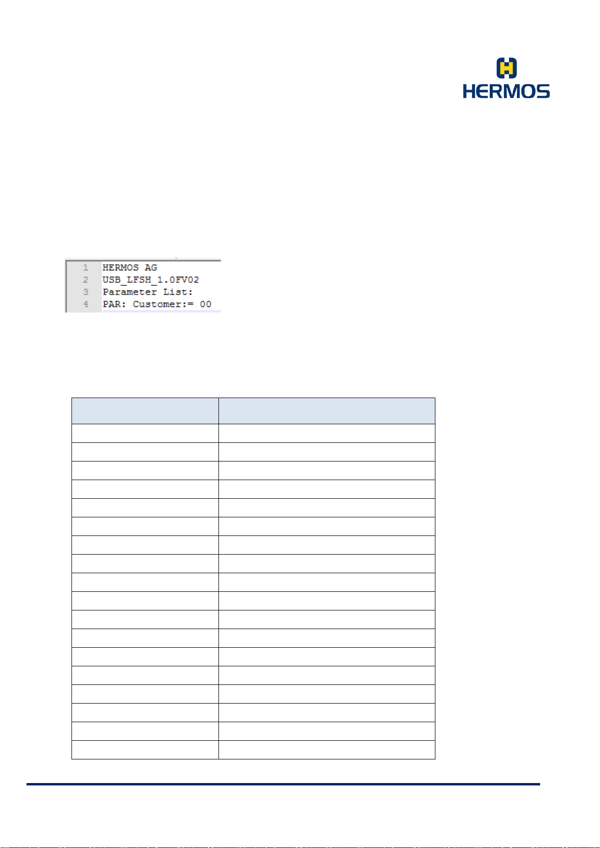
Parameter Name Short Description
Customer Selection of customer settings
Retry Number of read attempts
ShowTagType Show tag type
ReadPage Page of the tag to be read
ReadLength Length of the read data
MIDFormat Formatting the MID
Polling Activate polling mode
AddTabCR Add carriage return or tab
ASCIICoded Output in ASCII or HEX format
Prefix Preceding character before reading result
Suffix Subsequent character after reading result
Language Language setting keyboard
Peep/Summer Switching the signal buzzer on or off
ShowNoneVisibleASCII Display of invisible signs
NumPrefix Number of prefix characters
NumSuffix Number of suffix characters
PollingFrequenz Reading frequency in polling mode
SpecialSettings Configuring Special Settings
HERMOS AG
Gartenstra s se 19 Tel. +49(9279) 991-0
D-95490 M istelgau Fax. +49(9279) 991-100
Page 25

Product Manual
Customer Documentation
Version 1.0
LFP Handhe ld Ke yb oar demul ati on 07.06.2018
Page 25 of 75
7.3.2.1 Parameters - Customer
The parameter defines whether the reader is configured with the standard settings of the parameters or
with customer-specific settings.
Figures: Standard = 00
Custom er M ode 1 = 01
Custom er M ode 2 = 02
Standard: 00 (Standard Settings)
Custom er M ode P aram eter Set 1:
If the reader is in customer mode 1, the following parameters differ from the standard settings:
Parameter ReadPage 00
Parameter AddTabCR add Tab
Parameter Language English
In addition, the setup menu is locked when the reader is in customer mode 1. To access the setup menu,
press the following key combination:
Hold down the menu button and briefly press the read button 3 times. Then release the menu button. You
are now back in the parameter menu.
Custom er M ode P aram eter Set 2:
If the reader is in customer mode 2, the following parameters differ from the standard settings:
Parameter ReadPage 00
Parameter Prefix 19
Parameter Language English
7.3.2.2 Parameters - Retry
Defines the internal reading repetitions in case of an incorrect reading.
0x00 – 0x1F 0 to 31 Reading repetitions
Standard: 0x00
7.3.2.3 Parameters - ShowTagType
It is possible to display the ty pe of tran sponder. Fo r this purpose, a number for the t ransponder ty pe is output
before the actual transponder data. This behaviour can be switched on and off.
on Tr ansponder type is displayed
off Transponder type is not displayed
The transponder types are indicated by the following figures:
HERMOS AG
Gartenstra s se 19 Tel. +49(9279) 991-0
D-95490 M istelgau Fax. +49(9279) 991-100
Page 26

Product Manual
Customer Documentation
Version 1.0
LFP Handhe ld Ke yb oar demul ati on 07.06.2018
Page 26 of 75
01 - Read Only Transponder
02 - Read/Write Transponder
03 - Multipage Transponder
Standard: off
7.3.2.4 Parameters - ReadPage
This par am eter d efin es the star t po siti on ( page! ) of a rea d within a multipage transponder.
0x00 – 0x11 Page 1 to page 17
Standard: 0x01
If the value is 0, the different transponder types are read as follows:
Multipage Transponder - only page 1 is read (8 bytes)
Read Only - entire transponder is read (8 bytes)
Read/Write - entire transponder is read (8 bytes)
The transponder types Read Only and Read/Write can only be read with value 0.
7.3.2.5 Parameters - ReadLength
This par am eter d efin es the len gth of th e dat a (8-byte intervals) to be read during a read. The data of the
17 pages of a multi-page transponder can be read at most. The actual maximum possible number of bytes
to be read is limited by the first page to be read (parameter ReadPage) and is calculated from the
remaining pages.
0x08 – 0x88 read (n*8) bytes, where n = 1..17 (Page)
Standard: 0x08 (Read 8 bytes)
7.3.2.6 Parameters - MIDFormat
This parameter defines the format in which the MID data of the transponder are to be output.
0 : Not formatted; starting with the starting page
1 : MSB first output; starting with the end page; ends with the start page
2 : LSB first output; starting with the end page; ends with the start page
3 : MSB first output; starting with the start page; ending with the end page
4 : LSB first output; starting with the start page; ending with the end page
Standard: 0
Example: Data in transponder:
Data Page 1: - - - - 1234 (hex: 20 20 20 20 31 32 33 34).
HERMOS AG
Gartenstra s se 19 Tel. +49(9279) 991-0
D-95490 M istelgau Fax. +49(9279) 991-100
Page 27

Product Manual
Customer Documentation
Version 1.0
LFP Handhe ld Ke yb oar demul ati on 07.06.2018
Page 27 of 75
Data Page 2: 56789531 (hex : 35 36 37 38 39 35 33 31).
Output with different formats (StartPage=0, ReadLength=16 bytes):
Format 0: - - - - 123456789531 (Hex: 20 20 20 20 31 32 33 34 35 36 37 38 39 35 33 31).
Format 1: 56789531- - - -1234 (Hex: 35 36 37 38 39 35 33 31 20 20 20 20 31 32 33 34).
Format 2: 135987654321- - - - (Hex: 31 33 35 39 38 37 36 35 34 33 32 31 20 20 20 20).
Format 3: - - - - 123456789531 (Hex: 20 20 20 20 31 32 33 34 35 36 37 38 39 35 33 31).
Format 4: 4321- - - -13598765 (Hex: 34 33 32 31 20 20 20 20 31 33 35 39 38 37 36 35).
7.3.2.7 Parameters - Polling
This parameter defines whether the reader should work in polling mode (continuous reading at intervals of
parameter PollTimer). After the polling mode is activated in the parameter, the user has to press the read
button for the reader to start polling. Press the read button again to stop polling. With each successful
reading, the data is output.
off = 00 Polling off
on = 01 Polling on, activate the poll function with the read button.
on_read = 02 *) Polling on, activate the poll function with the read button.
Polling ends after the first successful reading.
on_reset = 03 *) Polling on, poll function is started automatically after a reset.
Standard: 0x00
*) not implemented in every software version
HERMOS AG
Gartenstra s se 19 Tel. +49(9279) 991-0
D-95490 M istelgau Fax. +49(9279) 991-100
Page 28

Product Manual
Customer Documentation
Version 1.0
LFP Handhe ld Ke yb oar demul ati on 07.06.2018
Page 28 of 75
7.3.2.8 Parameters - AddTabCR
This parameter defines whether a carriage return, a TAB or both is added to the end of the reading result.
none = 00 Do not add CR or TAB
add CR = 01 Add CR (ASCII 0x0D)
add T AB = 02 Add TAB (ASCII 0x09)
add CR TAB = 03 Add CR and TAB (ASC II 0x0D+0x09)
Standard: 0x01
7.3.2.9 Parameters – ASCII-Coded
The data read out can optionally be output in HEX or ASCII format.
HEX = 00 HEX format
ASCI I = 01 ASCII format
Standard: 0x01
7.3.2.10 Parameters - Prefix
This parameter defines whether the output string should be preceded by an additional character.
0x00 – 0x8F HEX code for prefix
Standard: 0x00 (No prefix)
7.3.2.11 Parameters - Suffix
This parameter defines whether an additional character is to be appended to the output string.
0x00 – 0x8F HEX code for suffix
Standard: 0x00 (kein Suffix)
7.3.2.12 Parameters - Language
This parameter defines the keyboard layout.
Englis h = 00 English layout
Germany = 01 German layout
Standard: 0x01
HERMOS AG
Gartenstra s se 19 Tel. +49(9279) 991-0
D-95490 M istelgau Fax. +49(9279) 991-100
Page 29

Product Manual
Customer Documentation
Version 1.0
LFP Handhe ld Ke yb oar demul ati on 07.06.2018
Page 29 of 75
7.3.2.13 Parameters - Peep/Summer
This parameter activates or deactivates the internal signal buzzer of the reader during the reading process.
off = 00 Buzzer off
on = 01 Buzzer on
Standard: 0x01
7.3.2.14 Parameter - ShowNoneVisibleASCII
This parameter defines whether a non-visible ASCII character on the screen is represented by a □ or not.
This parameter is only relevant for the ASCIICoded "ASCII" setting.
off = 00 □ not indicated
on = 01 □ indicated
Standard: 0x00
7.3.2.15 Parameters - NUMPrefix
Defines the numb er of pref ix characters to be added before the output string.
0x00 – 0x10 Number of pref ix characters
Standard: 0x00 (No prefix)
7.3.2.16 Parameters - NUMSuffix
Defines t he num b er of s uff ix characters to be added after the output string.
0x00 – 0x10 Number of suffix characters
Standard: 0x00 (No suffix)
7.3.2.17 Parameters - Polling Frequency
This parameter may not yet be available in all software versions!
The speed of the polling frequency is defined by this parameter.
0x00 Fastest frequency possible during polling
0x01 – 0x14 Breaks between polls. (Multiplication factor 100ms)
Standard: 0x0A
HERMOS AG
Gartenstra s se 19 Tel. +49(9279) 991-0
D-95490 M istelgau Fax. +49(9279) 991-100
Page 30

Product Manual
Customer Documentation
Version 1.0
LFP Handhe ld Ke yb oar demul ati on 07.06.2018
Page 30 of 75
7.3.2.18 Parameter - Special Settings
This par am eter s hou ld mak e it poss ibl e to ac tiva te f urth er s peci al fu ncti ons in the future.
This parameter is addressed bitwise (Bit0 to Bit7).
0x00 Standard behaviour
Standard: 0x00 (Standard behaviour)
HERMOS AG
Gartenstra s se 19 Tel. +49(9279) 991-0
D-95490 M istelgau Fax. +49(9279) 991-100
Page 31
Product Manual
Customer Documentation
Version 1.0
LFP Handhe ld Ke yb oar demul ati on 07.06.2018
Page 31 of 75
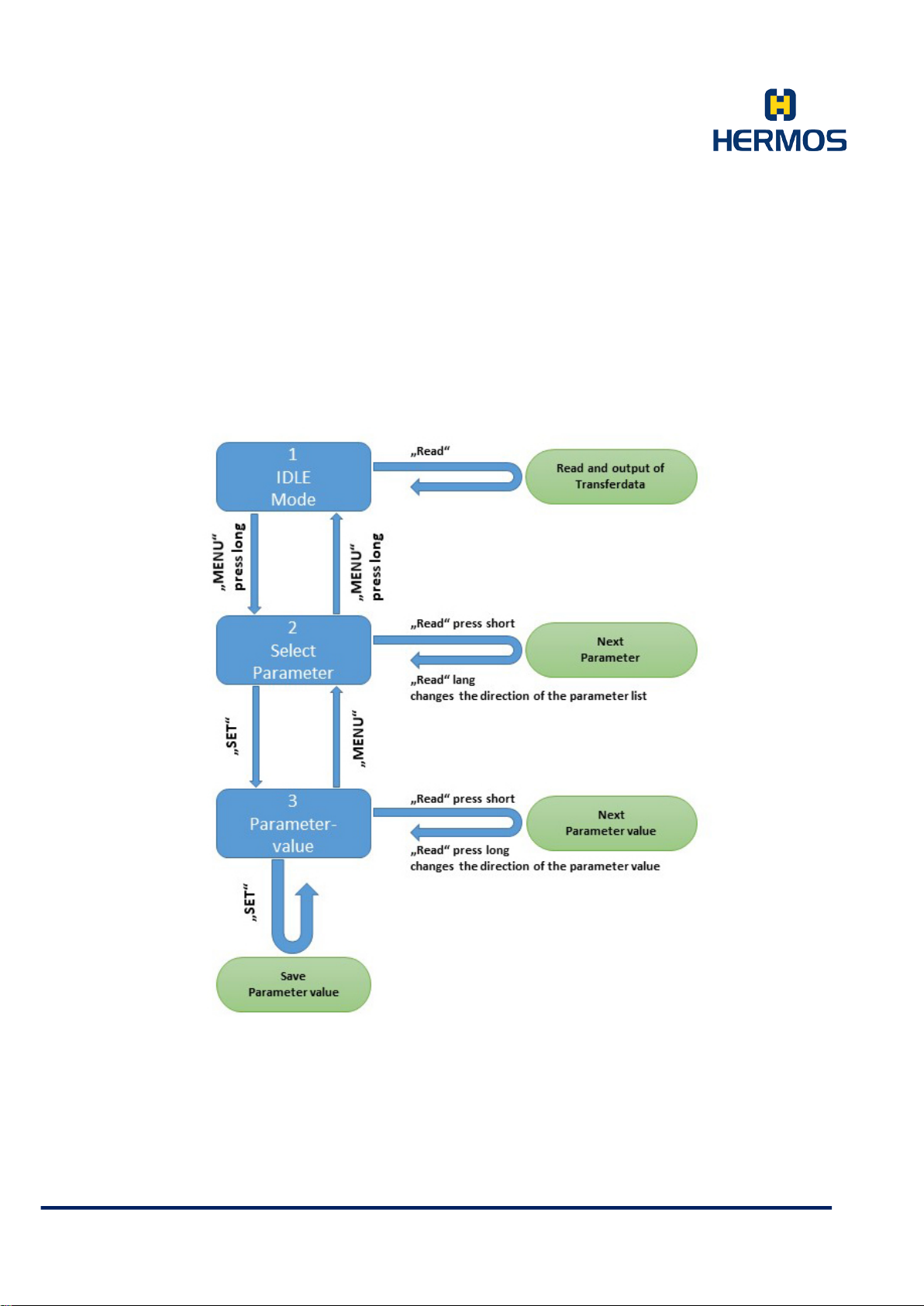
State Diagram Operating Modes
The following status diagram shows the operating modes and the transitions for the keyboard emulation
operating mode.
HERMOS AG
Gartenstra s se 19 Tel. +49(9279) 991-0
D-95490 M istelgau Fax. +49(9279) 991-100
Page 32
Product Manual
Customer Documentation
Version 1.0
LFP Handhe ld Ke yb oar demul ati on 07.06.2018
Page 32 of 75
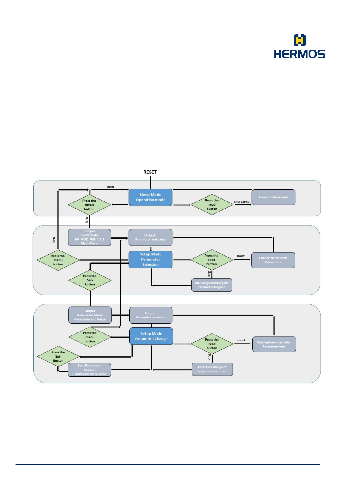
7.3.3 Process Diagram
HERMOS AG
Gartenstra s se 19 Tel. +49(9279) 991-0
D-95490 M istelgau Fax. +49(9279) 991-100
Page 33
Product Manual
DEZ
HEX
CTRL
Code
DEZ
HEX
CTRL
Code
0
0
^@
NUL
21
15
^U
NAK
^A
SOH
^V
SYN
2
2
^B
STX
23
17
^W
ETB
3
3
^C
ETX
24
18
^X
CAN
4
4
^D
EOT
25
19
^Y
EM
^E
ENQ
^Z
SUB
6
6
^F
ACK
27
1B
^[
ESC
7
7
^G
BEL
28
1C
^\
FS
^H
BS
^]
GS
9
9
^I
HT
30
1E
^^
RS
10
A
^J
LF
31
1F
^_
US
11
B
^K
VT
12
C
^L
EF
13
D
^M
CR
14
E
^N
SOH
15
F
^O
SI
16
10
^P
DLE
17
11
^Q
DC1
^R
DC2
19
13
^S
DC3
20
14
^T
DC4
Customer Documentation
Version 1.0
LFP Handhe ld Ke yb oar demul ati on 07.06.2018
Page 33 of 75
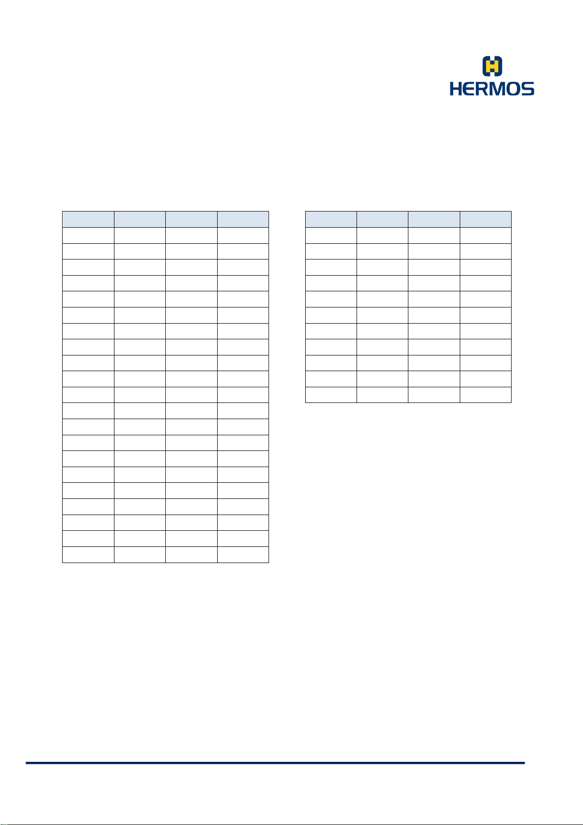
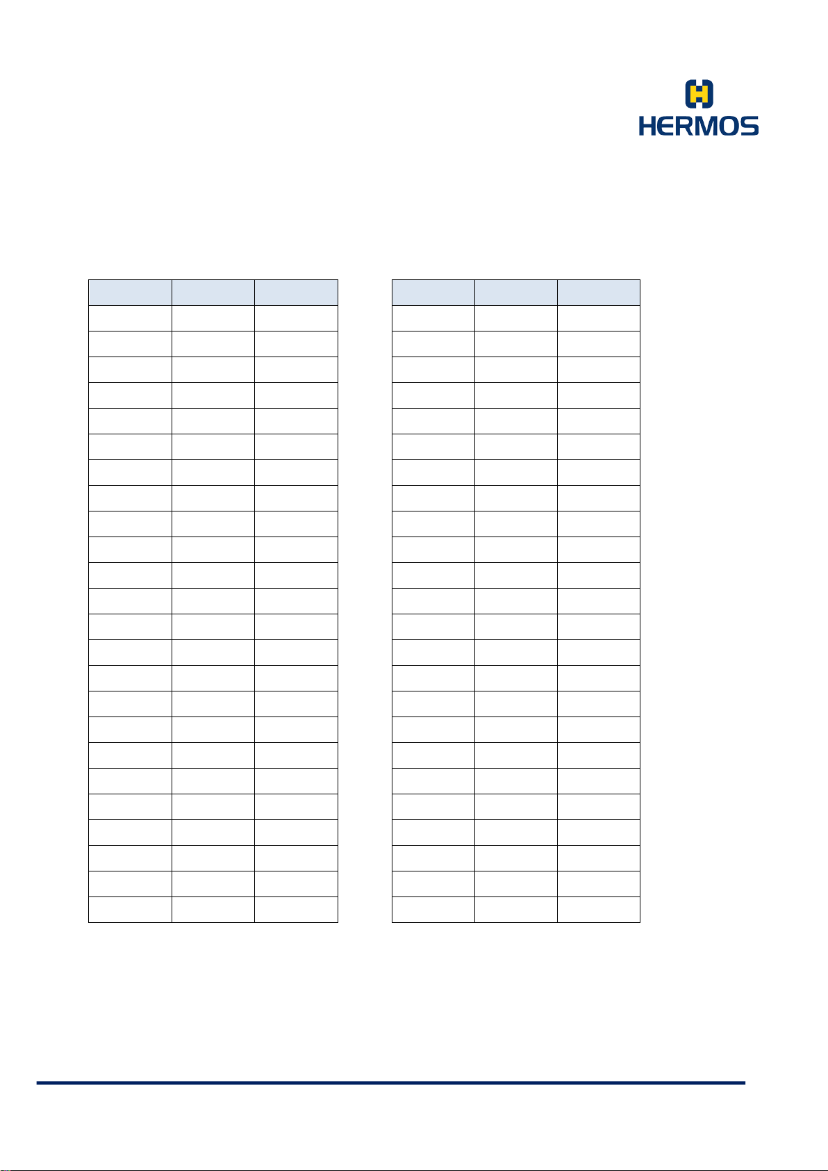
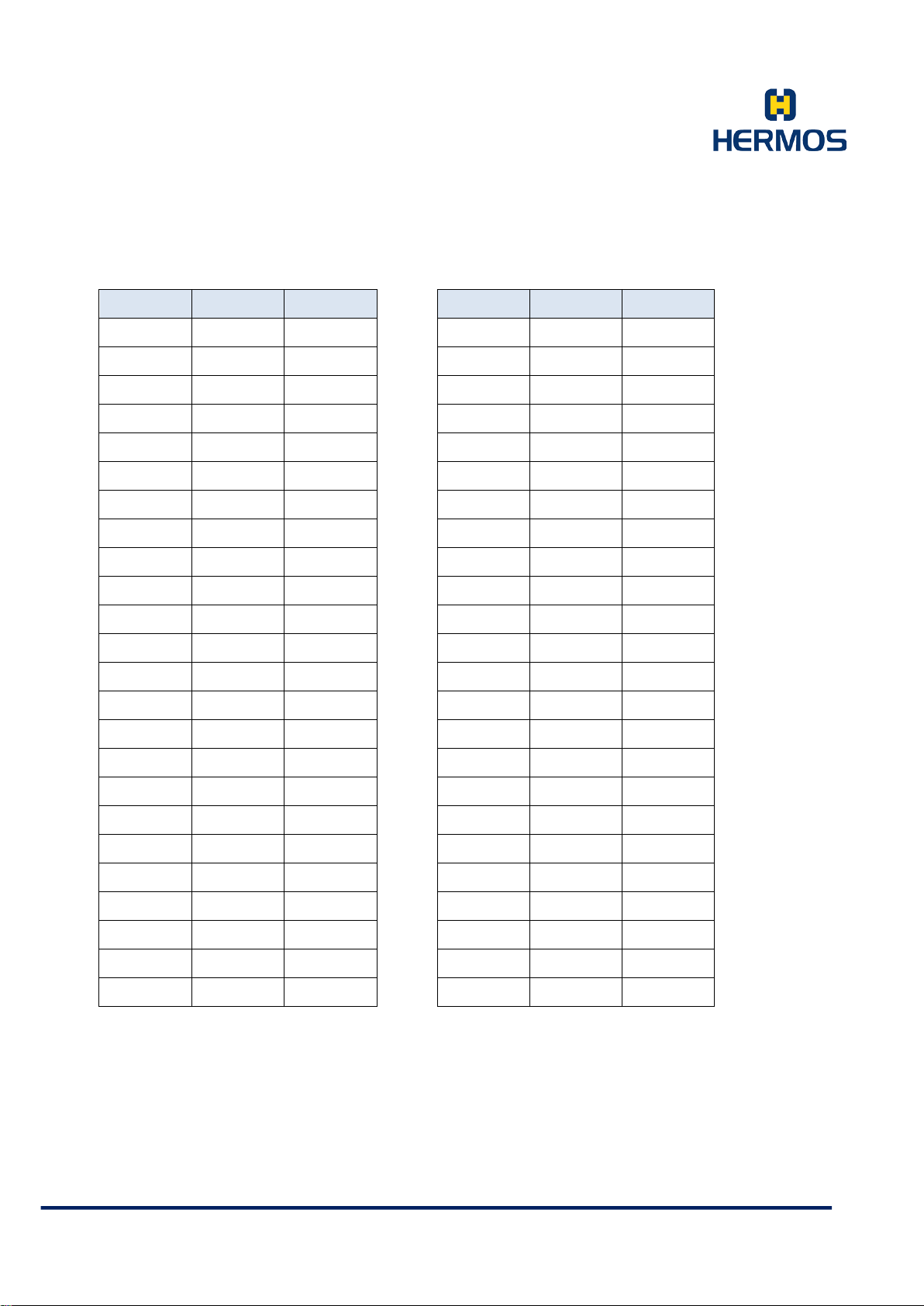
7.3.4 ASCII - Table
1 1
5 5
8 8
18 12
22 16
26 1A
29 1D
HERMOS AG
Gartenstra s se 19 Tel. +49(9279) 991-0
D-95490 M istelgau Fax. +49(9279) 991-100
Page 34
Product Manual
BLANK
8
!
9
"
:
#
;
$
<
%
=
&
>
'
?
(
@
)
A
*
B
+
C
,
D
-
E
.
F
/
G
0
H
1
I
2
J
3
K
4
L
5
M
6
N
7
O
Customer Documentation
Version 1.0
LFP Handhe ld Ke yb oar demul ati on 07.06.2018
Page 34 of 75
DEZ HEX CTRL
32 20
33 21
34 22
35 23
36 24
37 25
38 26
39 27
40 28
41 29
42 2A
43 2B
44 2C
45 2D
46 2E
DEZ HEX CTRL
56 38
57 39
58 3A
59 3B
60 3C
61 3D
62 3E
63 3F
64 40
65 41
66 42
67 43
68 44
69 45
70 46
47 2F
48 30
49 31
50 32
51 33
52 34
53 35
54 36
55 37
HERMOS AG
Gartenstra s se 19 Tel. +49(9279) 991-0
D-95490 M istelgau Fax. +49(9279) 991-100
71 47
72 48
73 49
74 4A
75 4B
76 4C
77 4D
78 4E
79 4F
Page 35
Product Manual
P
h
Q
i
R
j
S
k
T
l
U
m
V
n
W
o
X
p
Y
q
Z
r
[
s
\
t
]
u
^
v
_
w
'
x
a
y
b
z
c
{
d
|
e
}
f
~
g
□
Customer Documentation
Version 1.0
LFP Handhe ld Ke yb oar demul ati on 07.06.2018
Page 35 of 75
DEZ HEX CTRL
DEZ HEX CTRL
80 50
81 51
82 52
83 53
84 54
85 55
86 56
87 57
88 58
89 59
90 5A
91 5B
92 5C
93 5D
94 5E
95 5F
104 68
105 69
106 6A
107 6B
108 6C
109 6D
110 6E
111 6F
112 70
113 71
114 72
115 73
116 74
117 75
118 76
119 77
96 60
97 61
98 62
99 63
100 64
101 65
102 66
103 67
HERMOS AG
Gartenstra s se 19 Tel. +49(9279) 991-0
D-95490 M istelgau Fax. +49(9279) 991-100
120 78
121 79
122 7A
123 7B
124 7C
125 7D
126 7E
127 7F
Page 36
Product Manual
0x0B
CTRL-K
0x8B
F11
Customer Documentation
Version 1.0
LFP Handhe ld Ke yb oar demul ati on 07.06.2018
Page 36 of 75
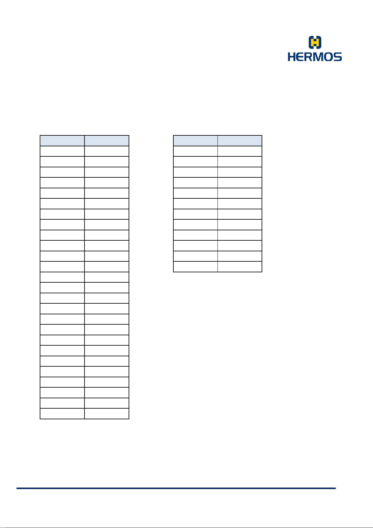
7.3.5 Control and Function Symbols
HEX Button
0x01 CTRL-A
0x02 CTRL-B
0x03 CTRL-C
0x04 CTRL-D
0x05 CTRL-E
0x06 CTRL-F
0x07 CTRL-G
0x08 CTRL-H
0x09 CTRL-I
0x0A CTRL-J
0x0C CTRL-L
0x0D CTRL-M
0x0E CTRL-N
0x0F CTRL-O
0x10 CTRL-P
0x11 CTRL-Q
0x12 CTRL-R
0x13 CTRL-S
0x14 CTRL-T
0x15 CTRL-U
0x16 CTRL-V
0x17 CTRL-W
0x18 CTRL-X
0x19 CTRL-Y
0x1A CTRL-Z
HEX Button
0x81 F1
0x82 F2
0x83 F3
0x84 F4
0x85 F5
0x86 F6
0x87 F7
0x88 F8
0x89 F9
0x8A F10
0x8C F12
HERMOS AG
Gartenstra s se 19 Tel. +49(9279) 991-0
D-95490 M istelgau Fax. +49(9279) 991-100
Page 37

Product Manual
Customer Documentation
Version 1.0
LFP Handhe ld Ke yb oar demul ati on 07.06.2018
Page 37 of 75
7.4 ASCII Protocol Operating Mode
If the device is plugged in or restarted, the ASCII protocol operating mode is indicated by the following
combination of LEDs and signal buzzers:
- The antenna LED, the status LED and the buzzer are briefly switched on and off again (test of the
membrane keypad).
- Short waiting time
- The antenna LED is switched on and off briefly at least one more time.
The LFP reader USB communicates with a higher-level host system via a virtual COM port using the ASCII
protocol. To read a transponder, hold the device near a transponder and press the read button.
An active reading is indicated by the antenna LED lighting up.
The LFP reader reads the transponder and transmits the read data either via the standard ASC-I1 pr otoc o l
or the ASC-W1 protocol. Both protocols are ASCII protocols and differ only slightly in commands and
parameters. The desired ASCII protocol specification is selected via parameter 64. In the following
chapters, the different specifications are indicated at the appropriate points.
7.4.1 Structure of the Communication Protocol
Communication is carried out via ASCII packets.
A specific response is sent to the reader after each command. We recommend waiting for this response
before sending a new command.
7.4.2 Packet Content
Each message packet consists of a packet header (header = 3 characters), the message data (2 or more
characters) and the packet end.
Packet Header Message Data Packet End
Packet Header
The packet header contains a start character and the message length. The message length consists of 2
hexadecimal bytes and defines the number of characters in a message.
Packet Header
Start Character Length 1 (high byte) Length 2 (low byte)
Start Start character (ASCII character „S“)
Length 1 High byte of the message length (ASCII character „0“-“F“)
Length 2 Low byte of the message length (ASCII character „0“-“F“)
HERMOS AG
Gartenstra s se 19 Tel. +49(9279) 991-0
D-95490 M istelgau Fax. +49(9279) 991-100
Page 38

Product Manual
Customer Documentation
Version 1.0
LFP Handhe ld Ke yb oar demul ati on 07.06.2018
Page 38 of 75
Advanced ASCII format:
The advanced ASCII format is defined for ASCII messages whose message length exceeds 255
characters. The packet header contains two start characters and the message length. The message length
consists of 4 hexadecimal bytes and defines the number of characters in a message.
Packet Header
Start 1 Start 2 Length 1 Length 2 Length 3 Length 4
Start 1 First start character (ASCII character „S“)
Start 2 Secon d s tar t c ha r act er (ASCII character "X" = extended ASCII protocol)
Length 1 High byte of the message length (ASCII-character „ 0“-„F“)
Length 2 Byte packet length (ASCII character „0“-“F“)
Length 3 Byte packet length (ASCII character „0“-“F“)
Length 4 Low byte of the message length (ASCII character „0“-“F“)
Message Data
The message contains a command character, a target or source address and the actual message data.
Message Data
Command Address Data
Command The command is defined by an ASCII character. (See protocol commands)
Address Target /s ourc e ad dr ess ( ASC II c har ac te rs „ 0“, „ 1“ , …, „E“) *
Data The defi nit ion of the message data depends on the protocol command.
* The reader address can be set via parameters. When delivered, the address is set to "0".
Packet End
The packet end contains an end character and a checksum consisting of 4 characters.
Packet End
End Character Checksum 1 Checksum 2 Checksum 3 Checksum 4
Character ASCII end character <CR> (hex 0x0D).
Checksum 1 High byte XOR logic of all data (packet header, data and end character).
(ASCII character „0“…“F“)
Checksum 2 Low byte XOR logic of all data (packet header, data and end character).
End
HERMOS AG
Gartenstra s se 19 Tel. +49(9279) 991-0
D-95490 M istelgau Fax. +49(9279) 991-100
Page 39
Product Manual
Customer Documentation
Version 1.0
LFP Handhe ld Ke yb oar demul ati on 07.06.2018
Page 39 of 75
(ASCII character „0“…“F“)
Checksum 3 High byte addition of all data (packet header, data and end character).
(ASCII character „0“…“F“)
Checksum 4 Low byte addition of all data (packet header, data and end character).
(ASCII character „0“…“F“)
7.4.3 Data Elements
The data elements that are used by default ASCII messages, which are described in the message
details section, are defined in this section.
CMD 1 Byte
Command of the message, see table in Chapter “Commands“.
Data 16 Bytes
The data is represented in HEX format by 2 ASCII characters. The data always includes every 8
bytes of the corr es ponding page of the transporter.
Example:
Transponder data in ASCII-Format „12345678“ (8 bytes)
Transponder data in HEX-Format 0x31 0x32 0x33 0x34 0x35 0x36 0x37 0x38
Data in message „3132333435363738“ (16 ASCII-characters)
Output Index 1 Byte
The output index defines the index of the output that is addressed.
1 Signal buzzer
2 Antenna LED
3 Status LED
Output State 1 Byte
The data element shows or sets the current status of the outputs.
0 Switch off the output permanently
1 Switch on the output permanently
2 Output flashes with approx. 1 Hz
HERMOS AG
Gartenstra s se 19 Tel. +49(9279) 991-0
D-95490 M istelgau Fax. +49(9279) 991-100
Page 40

Product Manual
Customer Documentation
Version 1.0
LFP Handhe ld Ke yb oar demul ati on 07.06.2018
Page 40 of 75
3 Output remains unchanged
4 Output flashes with approx. 2 Hz
Parameter No. 1 Byte
The number of the parameter is displayed as an ASCII character in HEX for m at.
Example: Par amet er 1 "0 1" ( 2 ASC II c harac ter s: 0x 30, 0x 31)
Parameter 10 "0A" ( 2 A SCII c harac ter s: 0x3 0, 0x4 1)
Parameter 20 "14" (2 ASCII char ac ters : 0x3 1, 0x 34)
In ASC-W1 mode, the data element displays the number of a parameter in hexadecimal format ("0" to
"F") using 1 ASCII character.
Example: Parameter 1 "1 " (1 ASCII character: 0x31)
Parameter 15 "F " (1 ASCII character: 0x46)
Parameter Value 2 Bytes
In the standard ASC-I1 mode, the data element displays the value of a parameter using 2 ASCII
charac ters (2 b ytes) in decimal format (“00” bis “99”).
Example: Value 45 "45" (2 ASCII characters: 0x 34, 0x 3 5)
In ASC-W1 mode the data element indicates the value of a parameter by means of 2 ASCII characters
(2 bytes) in hexadecimal format („ 00“ t o „FF“) .
Example: Value 45 ( decimal) "2D" (2 ASCII characters: 0x32, 0x44 )
Reader-ID 1 Byte
The reader ID defines the address of the device „0“ to „E“.
Adjustable via parameters.
Response-Code 4 Bytes
This feature is not required for the individual device. This code is always „0000“.
Page 1 Byte
HERMOS AG
Gartenstra s se 19 Tel. +49(9279) 991-0
D-95490 M istelgau Fax. +49(9279) 991-100
Page 41

Product Manual
Customer Documentation
Version 1.0
LFP Handhe ld Ke yb oar demul ati on 07.06.2018
Page 41 of 75
The page of the transponder for a read / write operation is defined by 2 ASCII characters (2 bytes) in
decimal format.
Example: Page 1 "01"
Page 10 "10"
Page 17 "17"
If the device is operating in ASC-W1 mode, the page should be interpreted in hexadecimal form:
The page of the transponder for a read / write operation is defined by 2 ASCII characters (2 bytes) in
hexade cim al f orm at .
Example: Page 1 "01" („81“ if page is l ock ed)
Page 10 "0A" („8A“ if page is lock ed)
Page 17 "11" („91“ if page is lock ed)
Read/Only "F0"
Read/Write "F1"
Serial Number 4 Bytes
Contains the 4-byte long serial number of the device.
The serial number is located on the bottom of the reader's label.
Example: "1707HAG04660" complete ser ia l number
Decimal „04660“ (the last 5 characters of the complete serial number)
Hexadecim al s er ial num be r „1234“
The gateway ID is the last two digits and has the value 0x34
Software Version 16 Bytes
The data item contains the software version currently used in the reader.
The version string is displayed with up to 16 characters.
Example: "4C464D3449312E31" hex-String („LFM4I1.1“)
Button No. 1 Byte
Displays the number of the button as an ASCII character whose status has changed or is being
queried.
HERMOS AG
Gartenstra s se 19 Tel. +49(9279) 991-0
D-95490 M istelgau Fax. +49(9279) 991-100
Page 42
Product Manual
Customer Documentation
Version 1.0
LFP Handhe ld Ke yb oar demul ati on 07.06.2018
Page 42 of 75
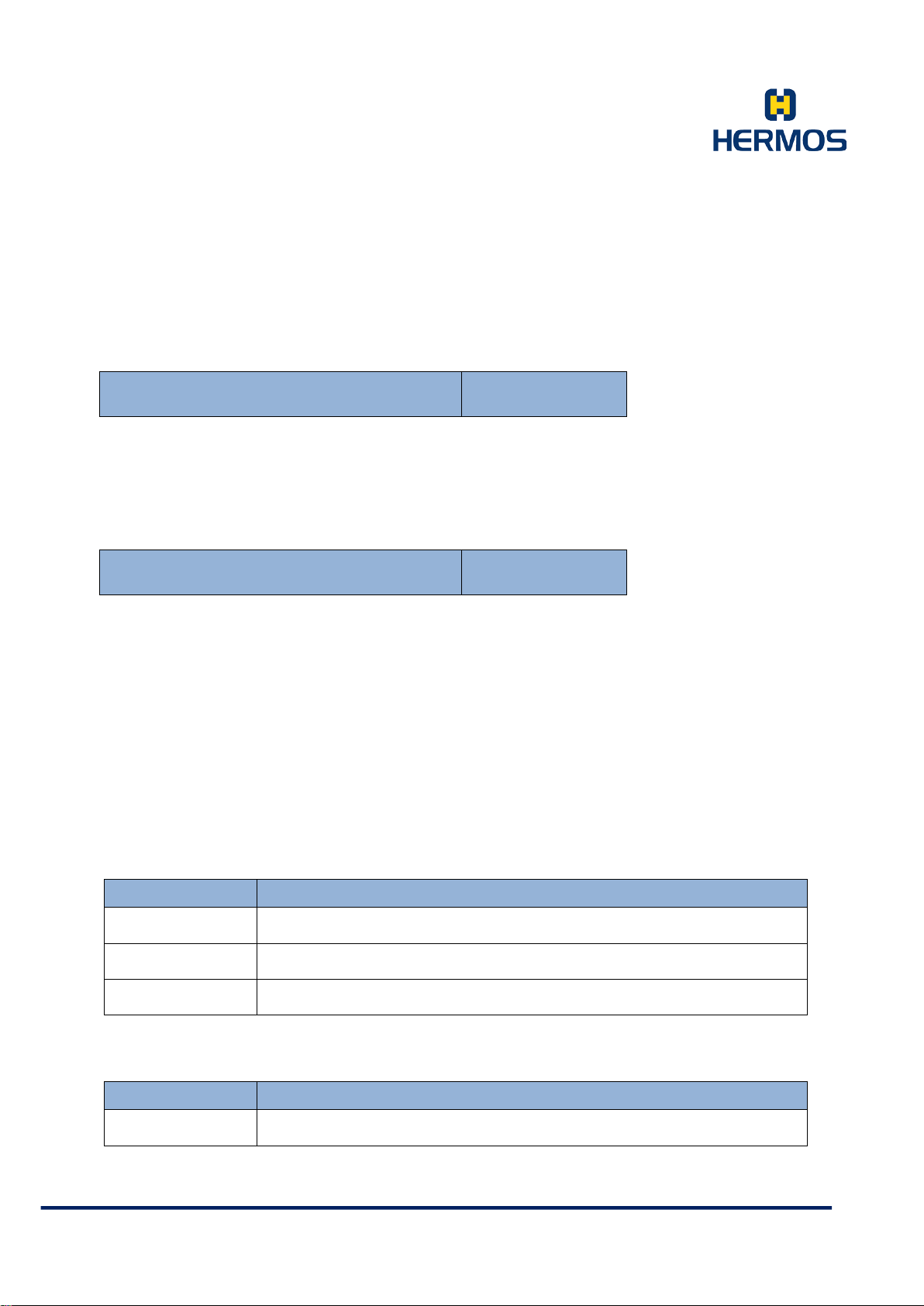
Value „1“ Read button
Value „2“ Set button
Value „3“ Menu button
Button State 1 Byte
Displays the current status of the respective button as an ASCII character.
Value „0“ But ton is not pressed
Value „1“ Bu tt on is pr es sed
Timeout 2 Bytes
The data element Timeout defines the period of time that elapses until the LEDs are switched off.
The timeout is defined in hexadecimal notation.
When th e tim eout exp ires, the L ED t urns off .
Example: „00“ ... permanently on
„01“ to „FF“ ... 1 s to 255 s timeout
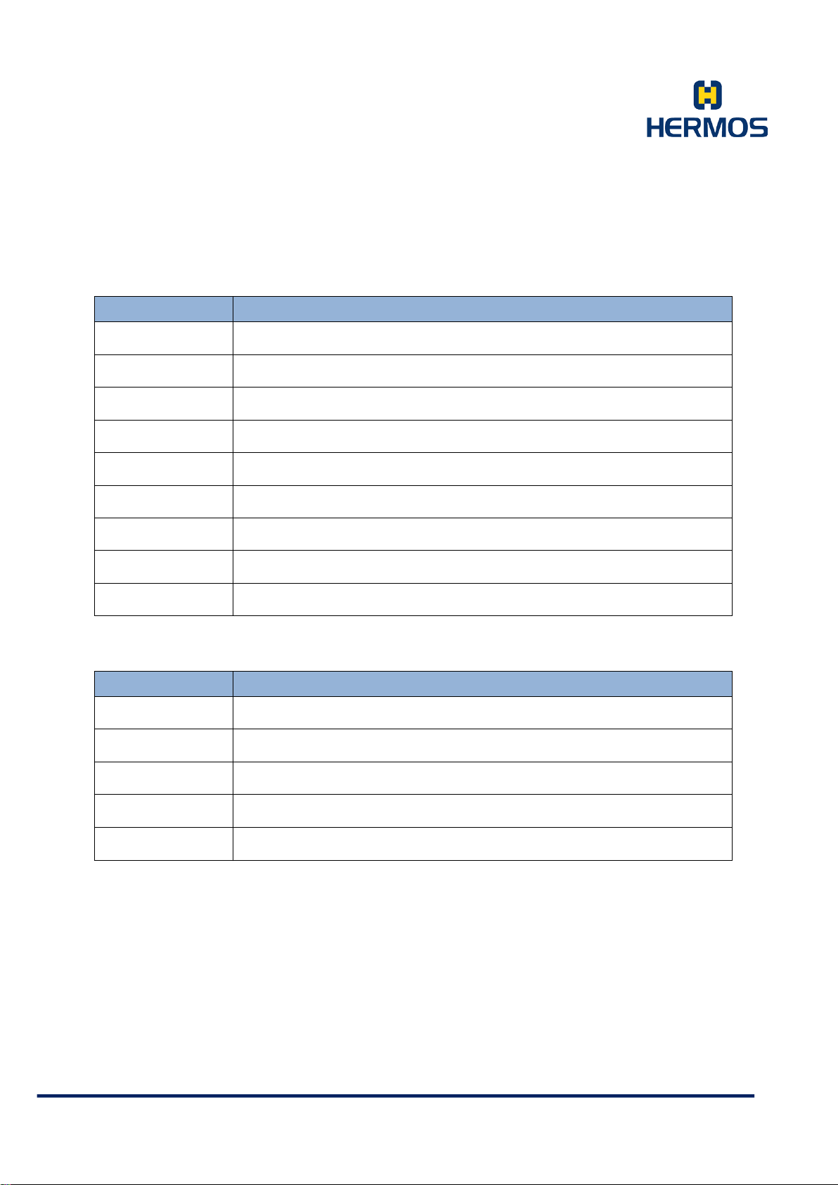
7.4.4 Protocol Commands
Read:
Command Description
X
R
K
Read Data
Automatic Read
Polling Read
Write:
Command Beschreibung
W
Write Data
HERMOS AG
Gartenstra s se 19 Tel. +49(9279) 991-0
D-95490 M istelgau Fax. +49(9279) 991-100
Page 43
Product Manual
Sensor event: Sensor detected (device is operated in ASC-W1 mode)
Sensor event: Change of a sensor status
Customer Documentation
Version 1.0
LFP Handhe ld Ke yb oar demul ati on 07.06.2018
Page 43 of 75
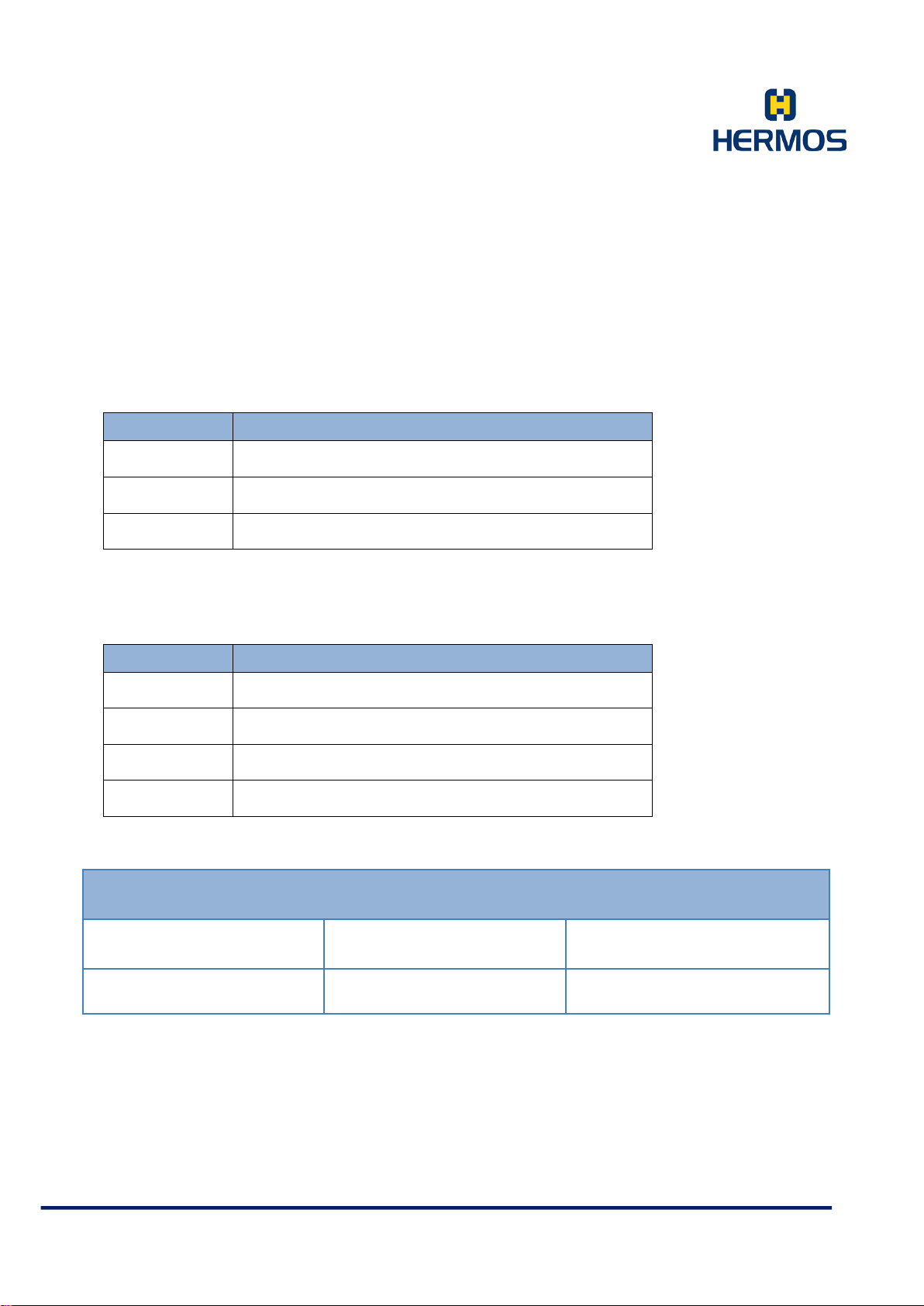
Settings:
Command Description
G
F
P
N
e
E
H
V
L
In- and Output:
Command Description
O
Q
A
B
B
Query Parameter
Query Parameter (Device is operated in ASC-W1 mode)
Set Param et er
Reset
Error Message
Error message (Device is operated in ASC-W1 m ode )
Heartbeat
Software Version
Lock page of a transponder
Set Output
Query Output/ Input State
Sensor event: Sensor removed (device is operated in ASC-W1 mode)
Sensor event: Change of a sensor status
HERMOS AG
Gartenstra s se 19 Tel. +49(9279) 991-0
D-95490 M istelgau Fax. +49(9279) 991-100
Page 44
Product Manual
Host LF Reading Device
Read multiple pages to the end character or a blank
charac ter 1 )
Customer Documentation
Version 1.0
LFP Handhe ld Ke yb oar demul ati on 07.06.2018
Page 44 of 75
7.4.4.1 X – Read Data
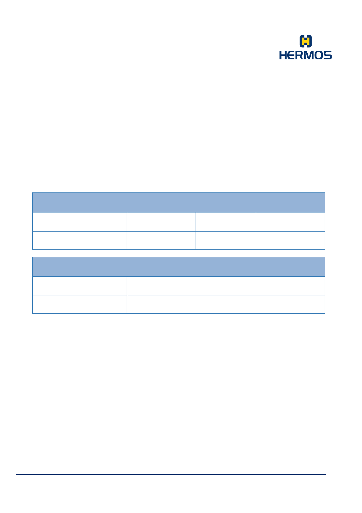
Command X starts reading a transponder.
If there is no transponder within the reading range of the antenna, the reader sends an error message
(error 4 - no transponder).
The data element "Page" can have the following values.
Value Description
„01“ … „17“
Read page #
„98“
„99“
Read out all transponder data
1) „E“ or „F“ in ID, Bit 0…3 of the read ID
In ASC-W 1 mode, the data element „page“ can have the following values:
Value Description ( ASC-W1 Mode )
„01“ … „11“
„F0“
„F1“
„00“
Read page # of a multipage transponder
Read/Only transponder
Read/Write transponder
Read the first page of all transponder types
CMD Reader-ID Page
X 1 Byte 2 Bytes
HERMOS AG
Gartenstra s se 19 Tel. +49(9279) 991-0
D-95490 M istelgau Fax. +49(9279) 991-100
Page 45

Product Manual
LF Reading Device Host
Customer Documentation
Version 1.0
LFP Handhe ld Ke yb oar demul ati on 07.06.2018
Page 45 of 75
CMD Reader-ID Page Data
x 1 Byt e 2 Bytes 16 Bytes
If there is no transponder in the reading range of the antenna, the reader repeats the reading function
several times before an error message is sent. The number of repetitions is defined in parameter 4 (‚r
/ w maxrepeat‘). If reading is still not possible, the reader sends the error message ‚no tag (4)‘ to the
host after the repetitions have been carried out.
No confirmation is expected from the host.
For a multi-page read request (98 or 99), the protocol is retried. At the end of reading, the reader
sends an additional packet.
If the sensor check is activated (parameter 1: readmode), the assignment of the external input is
checked before the initiation of a read process by the host. The reading process is only started if the
sensor is occupied, otherwise the error message ‚no tag (4)‘ is sent.
HERMOS AG
Gartenstra s se 19 Tel. +49(9279) 991-0
D-95490 M istelgau Fax. +49(9279) 991-100
Page 46
Product Manual
LF Reading Device Host
Host LF Reading Device
Customer Documentation
Version 1.0
LFP Handhe ld Ke yb oar demul ati on 07.06.2018
Page 46 of 75
7.4.4.2 R – Automatic Read
By assigning the external input, an automatic read operation can be triggered.
The command „R“ sends the read data to the host. The host then has to confirm the message.
Depending on the setting of the reader (parameter 1: readmode), the reader reads the following pages:
Read Mode:
0 Reading the page defined in parameter 2
1 sequential reading of a transponder to the end character
(‚E‘ - end charac ter or ‚F ‘ em pty) in ID bit 0 ... 3
2 Reading the entire transponder (all pages)
CMD Reader-ID Page Data
R 1 Byte 2 Bytes 16 Bytes
CMD Reader-ID
r 1 Byte
When reading several pages (par. 1: readmode „tag“ or „everything“) the command is repeated for
each read page. The last package contains the command ‚R‘ and the reader ID.
The host expects a confirmation of the read data. If there is no confirmation from the host, the
command is repeated. (Par.5: ‚RS232 delay time‘, par.6: ‚RS232 maxrepeat‘).
If a reading is not possible, the reader automatically repeats the reading with the set parameters.
(Par.3: ‚r / w delay time‘, par.4 ‚r / w maxrepeat‘).
If no reading is possible, the reader sends the error message ‚no tag (4)‘ to the host.
The dela y tim e for the presence sensor can be set (parameter 0: ‚sensor delay‘).
An automatic reading is only possible if all messages to be confirmed have been confirmed by the
previous reading or the waiting time (par.6: ‚RS232 repeattime‘) has elapsed after the last transmission.
HERMOS AG
Gartenstra s se 19 Tel. +49(9279) 991-0
D-95490 M istelgau Fax. +49(9279) 991-100
Page 47
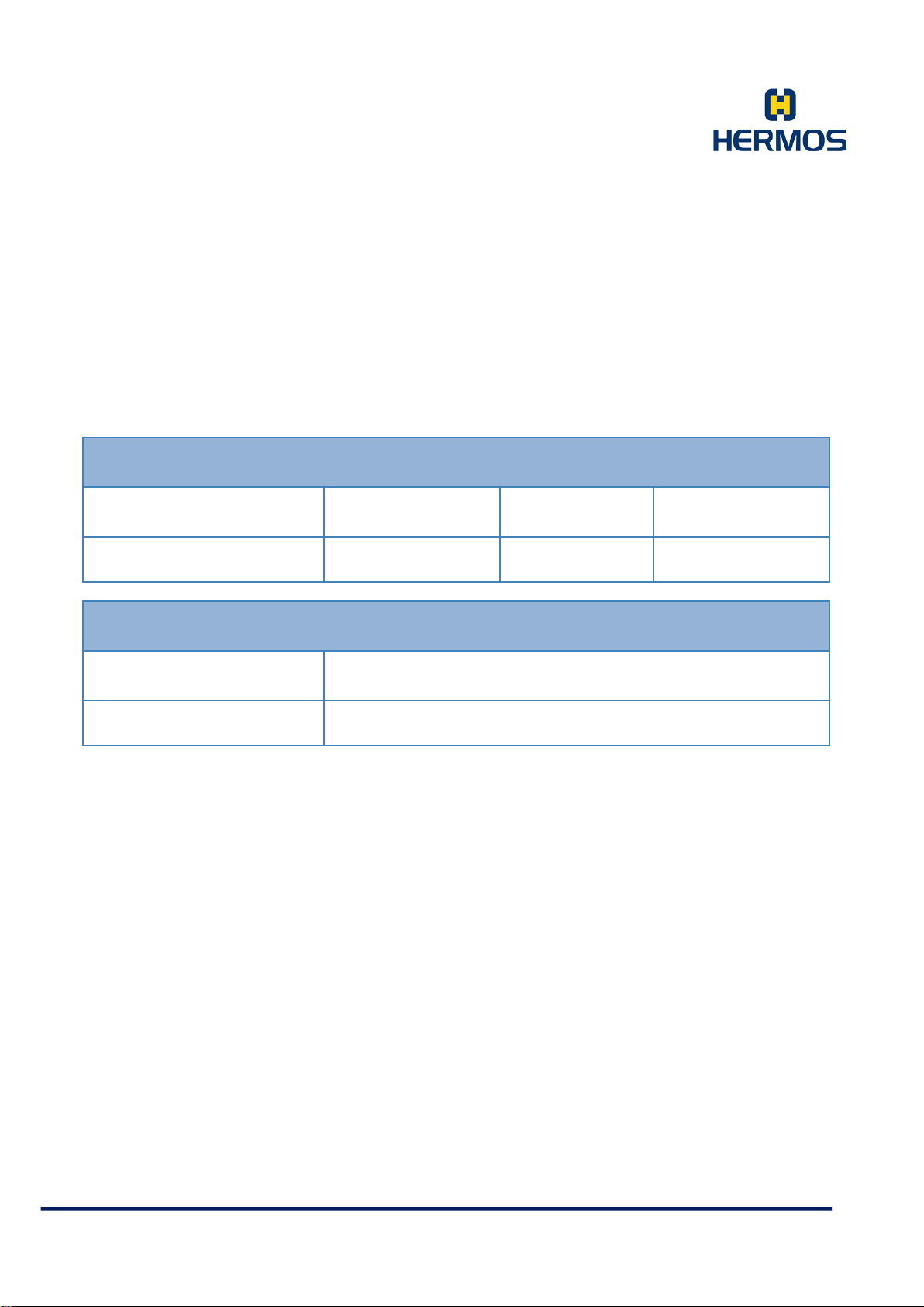
Product Manual
LF Reading Device Host
Host LF Reading Device
Customer Documentation
Version 1.0
LFP Handhe ld Ke yb oar demul ati on 07.06.2018
Page 47 of 75
7.4.4.3 K – Reading in Polling Mode
If the reader is in polling mode, cyclical readings are performed by the device. The reading frequency in
polling mode is determined by the polling frequency (parameter 39: Polling frequency). The data to be
read and the behaviour in polling mode is determined by further polling parameters (parameters 40 to
43). Polling mode is activated or deactivated via the polling frequency (parameter 39: polling frequency)
and the polling mode (parameter 40: polling mode). The read transponder data is automatically sent to
the host with the command "K".
CMD Reader-ID Page Data
K 1 Byte 2 Bytes 16 Bytes
CMD Reader-ID
k 1 Byt e
The setting of the polling mode (parameter 40: Polling Mode) determines whether a confirmation is
expected from the host or not. If there is no confirmation expected from the host, the command is
repeated. (Parameter 5: 'RS232 delay time'; Parameter 6: 'RS232 maxrepeat').
HERMOS AG
Gartenstra s se 19 Tel. +49(9279) 991-0
D-95490 M istelgau Fax. +49(9279) 991-100
Page 48
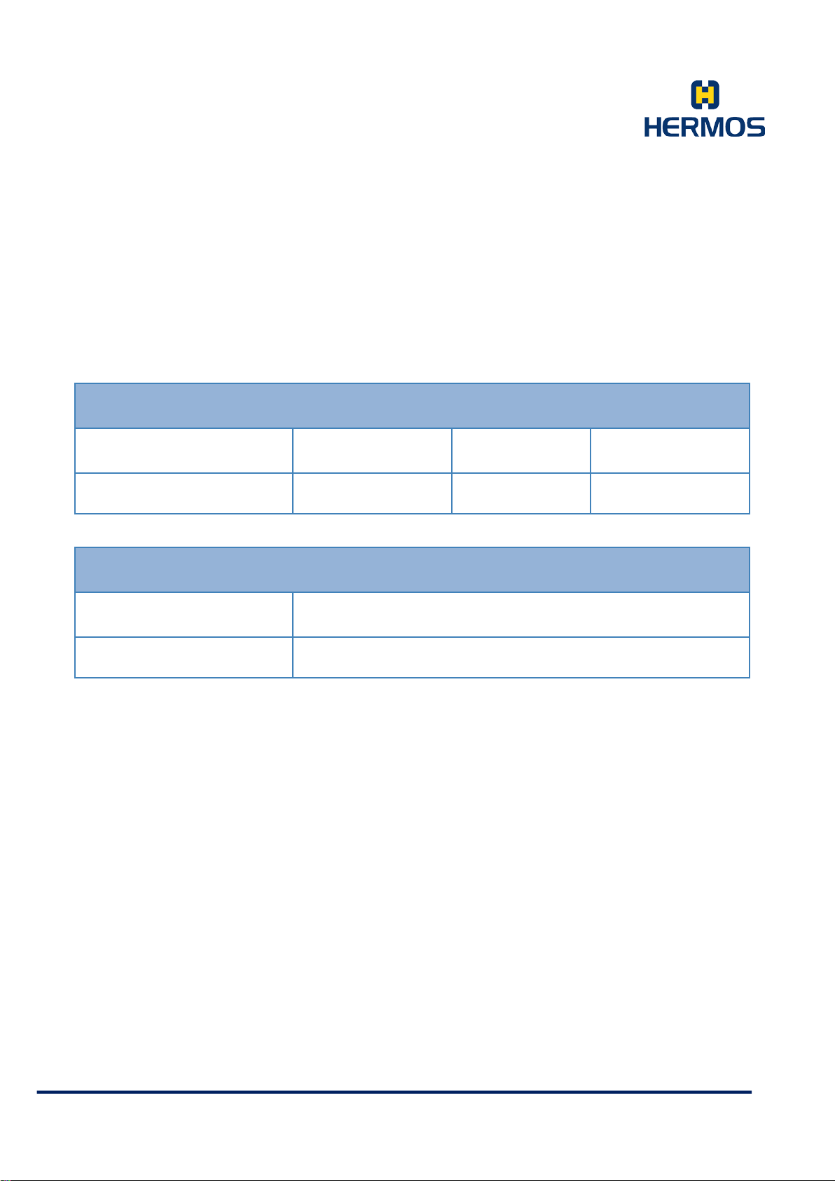
Product Manual
Host LF Reading Device
LF Reading Device Host
Customer Documentation
Version 1.0
LFP Handhe ld Ke yb oar demul ati on 07.06.2018
Page 48 of 75
7.4.4.4 W – Write Data
The command W starts writing a defined data area of a transponder.
If there is no transponder in the write range of the antenna, the reader sends an error message
(error 4 - no transponder).
CMD Reader-ID Page Data
W 1 Byte 2 Bytes 16 Bytes
CMD Reader-ID
w 1 Byte
If the describing of the tag fails, the reader repeats the writing operation several times before sending
an error message. The number of repetitions is defined in parameter 4 (‚r / w maxrepeat‘). If writing is
still not possible, the reader sends the error message ‚no tag (4)‘ to the host after the repetitions have
been carried out.
If the sensor check is activated (parameter 1: readmode), the assignment of the external input is
checked before the host starts the writing process. The writing process is only started if the sensor is
occupied, otherwise the error message 'no tag (4)' is sent.
HERMOS AG
Gartenstra s se 19 Tel. +49(9279) 991-0
D-95490 M istelgau Fax. +49(9279) 991-100
Page 49
Product Manual
Host LF Reading Device
LF Reading Device Host
Host LF Reading Device
LF Reading Device Host
Customer Documentation
Version 1.0
LFP Handhe ld Ke yb oar demul ati on 07.06.2018
Page 49 of 75
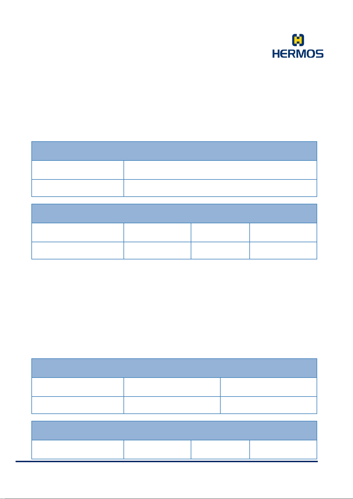
7.4.4.5 G – Query Parameter
With the command „G“ the values of all public parameters of the device can be queried.
CMD Reader-ID
G 1 Byte
CMD Reader-ID Parameter No. Parameter Value
g 1 Byte 1 Byte 2 Bytes
The reader sends an individual protocol packet for each available public parameter. After the last
parameter, the reader sends a last packet including the command ‚g‘ and the reader ID.
The values returned for the data item parameter value in the response are decimal values (00-99).
The values for the data item Parameter No. are hexadecimal values (0-F).
7.4.4.6 F – Query Parameter
The command „F“ can be used to query the value of a public parameter of the device.
CMD Reader-ID Parameter No.
F 1 Byte 2 Bytes
CMD Reader-ID Parameter No. Parameter Value
HERMOS AG
Gartenstra s se 19 Tel. +49(9279) 991-0
D-95490 M istelgau Fax. +49(9279) 991-100
Page 50
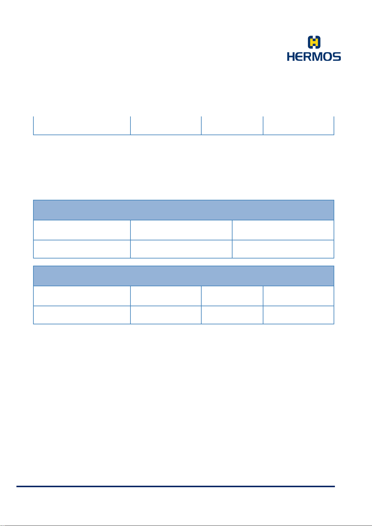
Product Manual
Host LF Reading Device
LF Reading Device Host
Customer Documentation
Version 1.0
LFP Handhe ld Ke yb oar demul ati on 07.06.2018
Page 50 of 75
f 1 Byte 2 Bytes 2 Bytes
The reader sends an individual protocol packet for the requested public parameter.
The values returned in the response for the da ta elem en ts p aram eter num ber a nd par am eter v alu e
are each hexadecimal values (00-FF).
In ASC-W1 mode, the following format results for the command F:
CMD Reader-ID Parameter No.
F 1 Byte 1 Byte
CMD Reader-ID Parameter No. Parameter Value
f 1 Byte 1 Byte 2 Bytes
The reader sends an individual protocol packet for the requested public parameter.
The val ues re tur ned i n the r espo nse for t he da ta e lemen ts p aram eter num ber a nd p aram eter value
are each hexadecimal values (00-FF).
HERMOS AG
Gartenstra s se 19 Tel. +49(9279) 991-0
D-95490 M istelgau Fax. +49(9279) 991-100
Page 51
Product Manual
Host LF Reading Device
LF Reading Device Host
Host LF Reading Device
LF Reading Device Host
Customer Documentation
Version 1.0
LFP Handhe ld Ke yb oar demul ati on 07.06.2018
Page 51 of 75
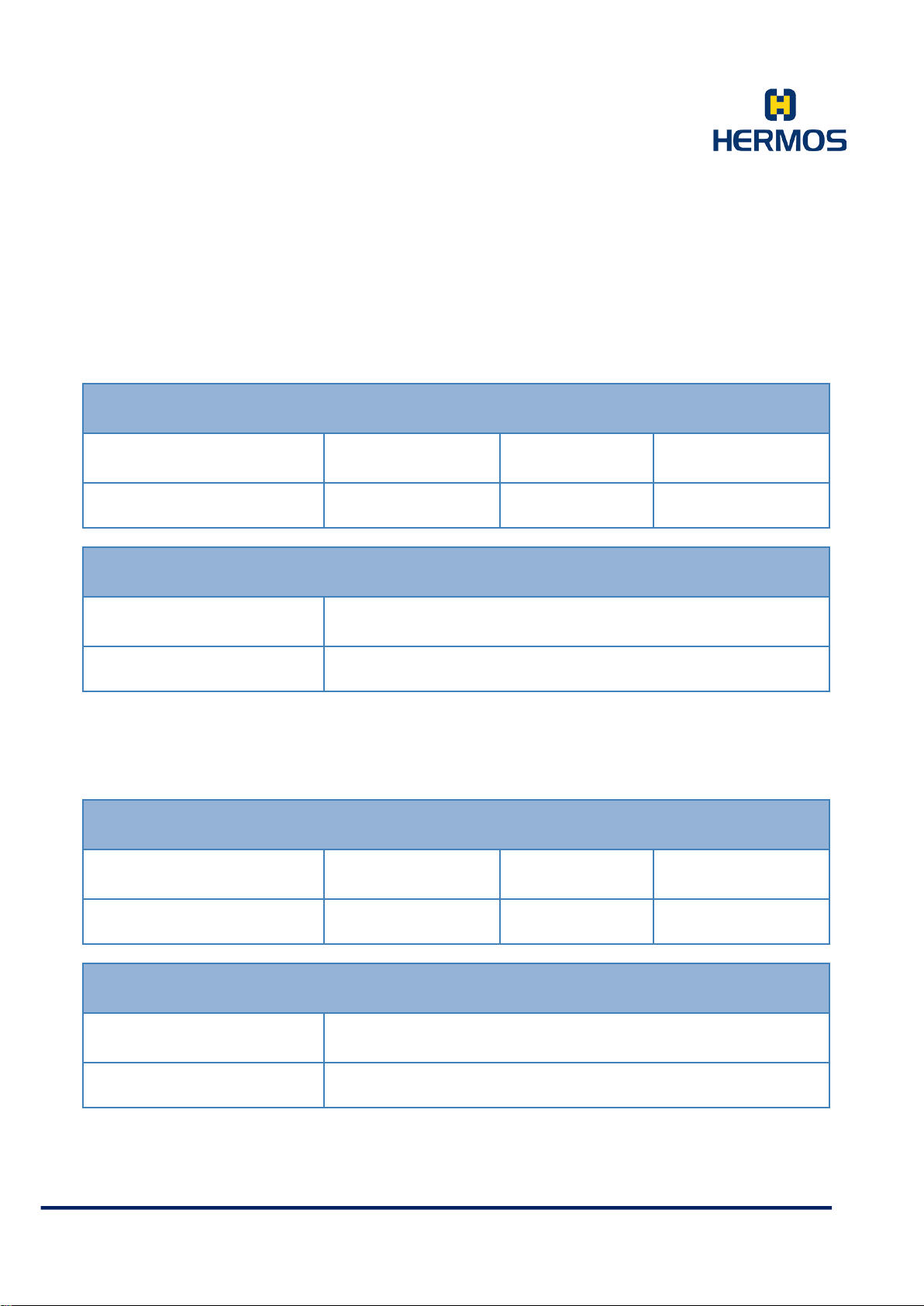
7.4.4.7 P – Set Parameters
The command „P“ can be used to change the value of individual parameters.
After a parameter has been successfully changed, the reader sends a confirm atio n m ess age .
CMD Reader-ID Parameter No. Parameter Value
P 1 Byte 2 Bytes 2 Bytes
CMD Reader-ID
p 1 Byte
The data elements parameter number and parameter value used in the query are each hexadecimal
values (00-FF).
In ASC-W1 mode, the following format is also supported for the P command:
CMD Reader-ID Parameter No. Parameter Value
P 1 Byte 1 Byte 2 Bytes
CMD Reader-ID
p 1 Byte
The data elements parameter number and parameter value used in the query are hexadecimal values
(0-F or 00-FF).
HERMOS AG
Gartenstra s se 19 Tel. +49(9279) 991-0
D-95490 M istelgau Fax. +49(9279) 991-100
Page 52
Product Manual
Host LF Reading Device
LF Reading Device Host
Customer Documentation
Version 1.0
LFP Handhe ld Ke yb oar demul ati on 07.06.2018
Page 52 of 75
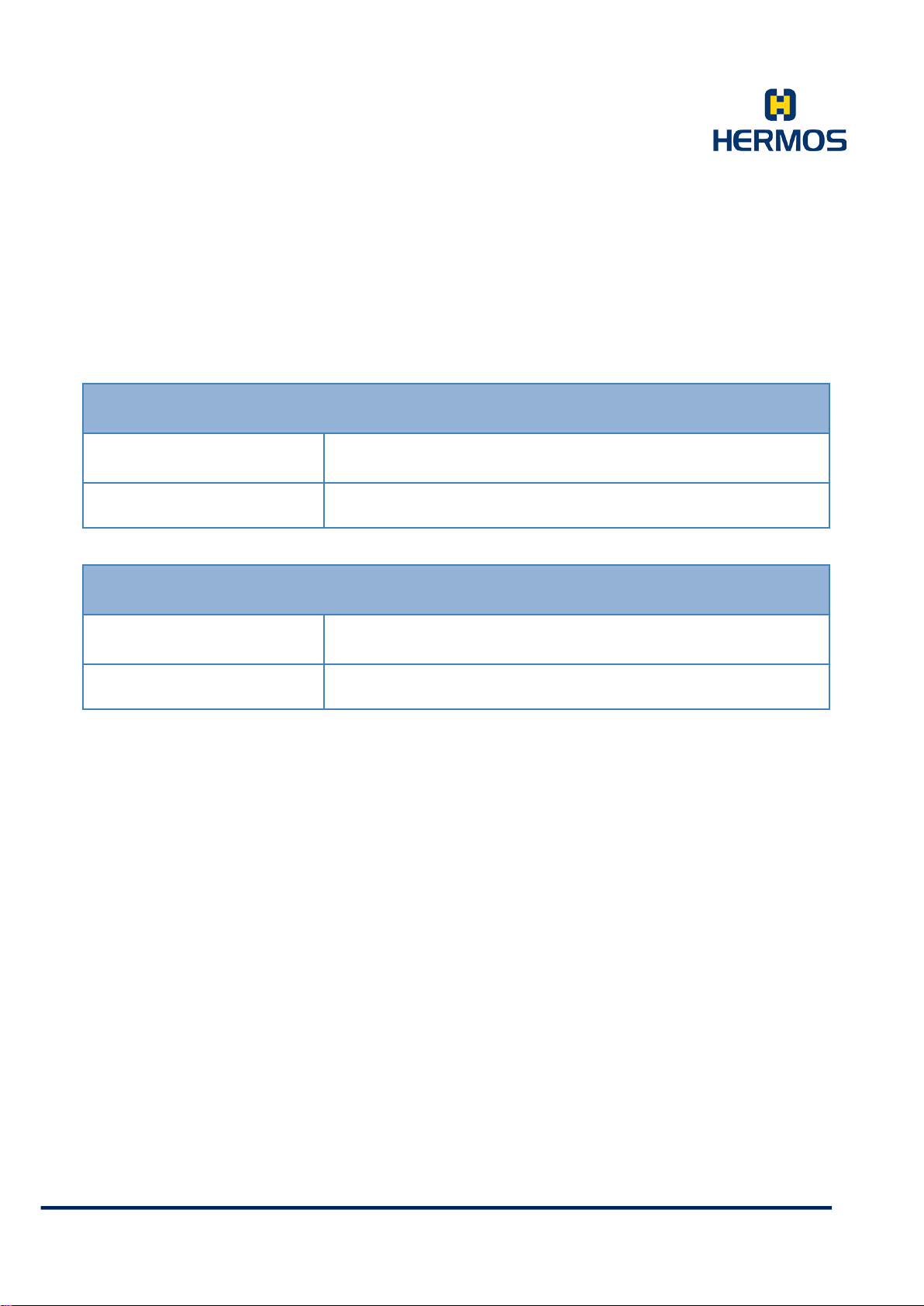
7.4.4.8 N – Reset
The command “N” performs a reset of the hardware/software of the reader.
After performing the reset operation, the device sends a confirmation message.
CMD Reader-ID
N 1 Byte
CMD Reader-ID
n 1 Byte
After a hardware reset, a confirmation („n0“) is sent to the host.
HERMOS AG
Gartenstra s se 19 Tel. +49(9279) 991-0
D-95490 M istelgau Fax. +49(9279) 991-100
Page 53
Product Manual
LF Reading Device Host
LF Reading Device Host
Host LF Reading Device
Customer Documentation
Version 1.0
LFP Handhe ld Ke yb oar demul ati on 07.06.2018
Page 53 of 75
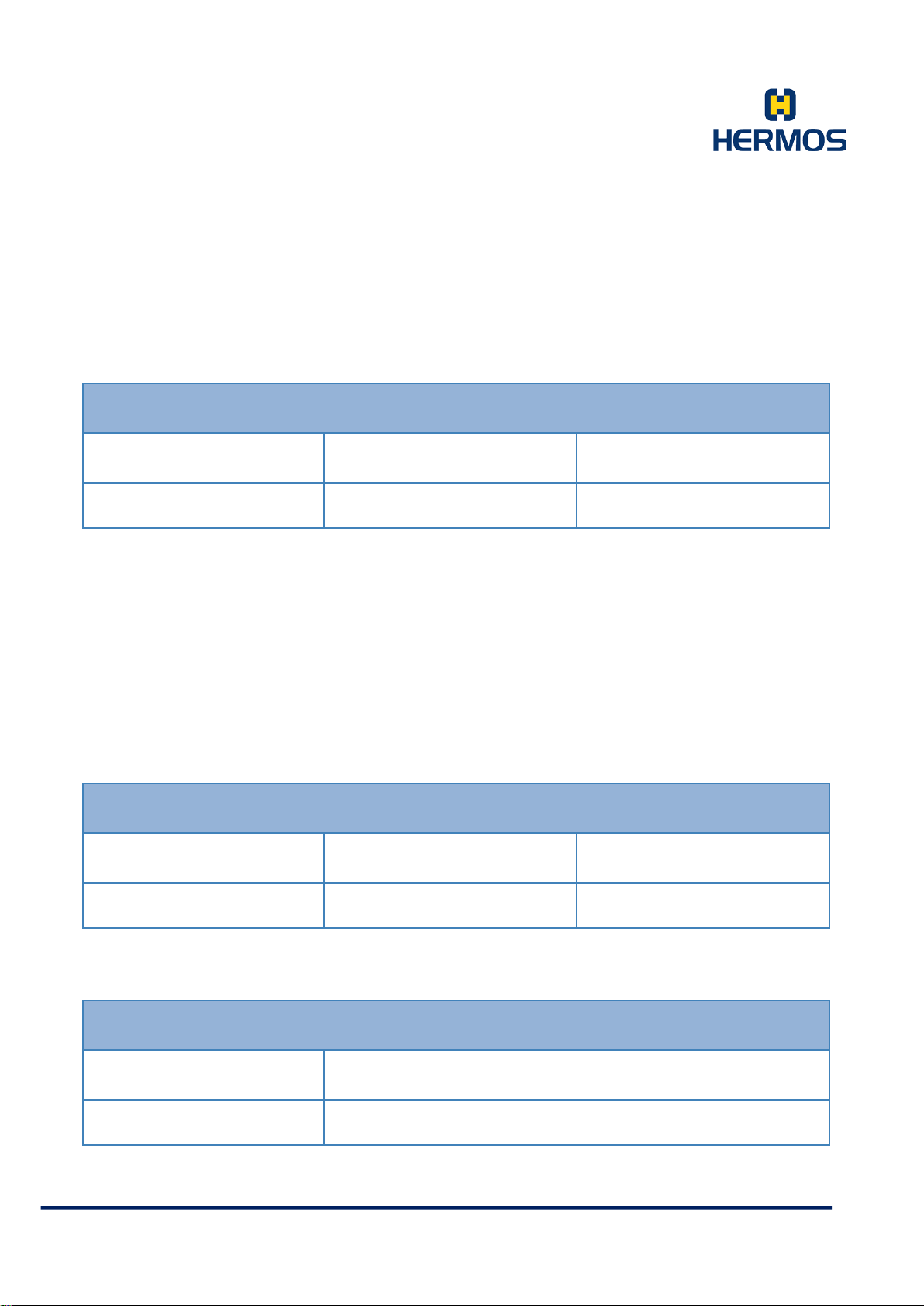
7.4.4.9 e – Error Message
This message is only available in standard ASC-I1 mo de!
If an err or oc curs the device will send an error message with the respective error code to the host.
CMD Reader-ID Error ID
e 1 Byt e 1 Byte
Further information about error codes and the corresponding corrective measures can be found in the
chapter Error C od es.
7.4.4.10 E – Error Message
This message is only available in ASC-W1 mode!
If an error occurs, the device sends an error message with the corresponding error code to the host.
The host expects a confirmation of the read data. If no confirmation is received from the host, the
command is repeated. (Par. 5: 'RS232 delay time'; Par. 6: 'RS232 maxrepeat').
CMD Reader-ID Error ID
E 1 Byte 1 Byte
Further information about error codes and the corresponding corrective measures can be found in the
chapter Err or Co des .
CMD Reader-ID
e 1 Byt e
HERMOS AG
Gartenstra s se 19 Tel. +49(9279) 991-0
D-95490 M istelgau Fax. +49(9279) 991-100
Page 54
Product Manual
Host LF Reading Code
LF Reading Device Host
Host LF Reading Device
LF Reading Device Host
Customer Documentation
Version 1.0
LFP Handhe ld Ke yb oar demul ati on 07.06.2018
Page 54 of 75
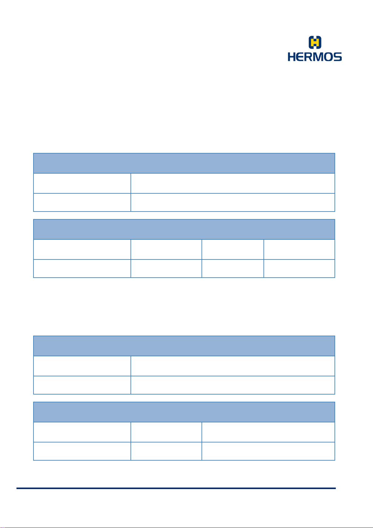
H – Heartbeat
The command „H“ sends a heartbeat request to the reader.
The reader responds with its serial number and a response code.
CMD Reader-ID
H 1 Byte
CMD Reader-ID Serial Number Response-Code
h 1 Byte 4 Bytes 4 Bytes
Only with the heartbeat command the address "F" (gateway address!) can also be used for the data
element reader ID. The response code is part of the protocol, but is not used for this device. The
response code is always'0000'.
V – Query Software Version
The command “V” is used to query the software version of the LF reading device.
CMD Reader-ID
V 1 Byte
CMD Reader-ID Software Version
v 1 Byt e 16 Bytes
HERMOS AG
Gartenstra s se 19 Tel. +49(9279) 991-0
D-95490 M istelgau Fax. +49(9279) 991-100
Page 55
Product Manual
Host LF Reading Device
LF Reading Device Host
Customer Documentation
Version 1.0
LFP Handhe ld Ke yb oar demul ati on 07.06.2018
Page 55 of 75
The 8 characters of the software version are represented by 16 ASCII characters. Each charac ter is
described in hex format and transmitted by 2 ASCII characters.
7.4.4.11 L – Lock Data Area
A single page of a multipage transponder can be disabled. The page can still be read, but not rewritten.
The process cannot be reversed.
CMD Reader-ID Page
L 1 Byte 2 Bytes
CMD Reader-ID
l 1 Byte
If the lock of the transponder page fails, the reader repeats the procedure seve ral times bef ore an err or
message is sent. The number of repetitions is defined in parameter 4 (‚r / w maxrepeat‘). If writing is
still not possible, the reader sends the error message ‚no tag (4)‘ to the host after the repetitions have
been carried out.
If the page was already locked, a positive confirmation will be sent (same as the first block).
If the sensor check is activated (parameter 1 readmode), the assignment of the external input is
checked
before the blocking process is started by the host. The locking process is only started when the
sensor is occupied, otherwise the error message ‚no tag (4)‘ is sent.
Locking a page cannot be rever s ed.
This page is permanently w r ite protected.
HERMOS AG
Gartenstra s se 19 Tel. +49(9279) 991-0
D-95490 M istelgau Fax. +49(9279) 991-100
Page 56
Product Manual
Host LF Reading Device
LF Reading Device Host
Customer Documentation
Version 1.0
LFP Handhe ld Ke yb oar demul ati on 07.06.2018
Page 56 of 75
7.4.4.12 A – Activation Button
This message is only available in ASC-W1 mode!
Sensor event messages can be activated in the "Watch Port" parameter (par. 07).
If this is activated, the reader reports every drop of the read button.
The message must be confirmed by the host.
CMD Reader-ID
A 1 Byte
CMD Reader-ID
a 1 Byt e
The button event is detected after an adjustable delay time (par. 0 Sensor Delay).
During the delay time, the sensor signal must be stable.
This message is only available in ASC-W1 mode!
All buttons can be deactivated in parameter 1 "Read Mode". The
buttons can also be deactivated individually via parameter 0x1A.
HERMOS AG
Gartenstra s se 19 Tel. +49(9279) 991-0
D-95490 M istelgau Fax. +49(9279) 991-100
Page 57
Product Manual
Host LF Reading Device
LF Reading Device Host
Customer Documentation
Version 1.0
LFP Handhe ld Ke yb oar demul ati on 07.06.2018
Page 57 of 75
7.4.4.13 B – Button Activated
This message is only available in ASC-W1 mode!
Sensor event messages can be activated in the "Watch Port" parameter (par. 07).
If this is activated, the reader reports every time the read button is pressed.
The sensor message must be confirmed by the host.
CMD Reader-ID
B 1 Byte
CMD Reader-ID
b 1 Byte
This message is only available in ASC-W1 mode!
All buttons can be deactivated in parameter 1 "Read Mode". The
buttons can also be deactivated individually via parameter 0x1A.
HERMOS AG
Gartenstra s se 19 Tel. +49(9279) 991-0
D-95490 M istelgau Fax. +49(9279) 991-100
Page 58
Product Manual
Host LF Reading Device
LF Reading Device Host
Customer Documentation
Version 1.0
LFP Handhe ld Ke yb oar demul ati on 07.06.2018
Page 58 of 75
7.4.4.14 B – Button Status Change
This message is only available in standard ASC-I1 mo de!
Sensor event messages can be activated in the "Watch Port" parameter (par. 07).
If this is activated, the reader reports every change of a button to the host.
Depending on the setting of the reader, the host must send a confirmation.
CMD Reader-ID Button No. Button State
B 1 Byte 1 Byte 1 Byte
CMD Reader-ID Button No.
b 1 Byte 1 Byte
All buttons can be dea c tiv ated in parameter 1 "Read Mode". The buttons
can also be deactiv a ted individually via parameter 0x 1 A.
HERMOS AG
Gartenstra s se 19 Tel. +49(9279) 991-0
D-95490 M istelgau Fax. +49(9279) 991-100
Page 59
Product Manual
Host LF Reading Device
Output
Index
Output
State
LF Reading Device Host
Customer Documentation
Version 1.0
LFP Handhe ld Ke yb oar demul ati on 07.06.2018
Page 59 of 75
7.4.4.15 O – Set Output
The command O can be used to set the state of the outputs.
The status of an output (Signal buzzer or LED) is changed in a message. In the current version, the
value of the data element Head-ID always has the value „1“ for the outputs.
CMD Reader-ID Head-ID
O 1 Byte 1 Byt e 1 Byte 1 Byte 2 Bytes
CMD Reader-ID Head-ID
o 1 Byte 1 Byte
* The specific ati on of a tim e durat ion (tim eout ) is optio nal.
Timeout *
HERMOS AG
Gartenstra s se 19 Tel. +49(9279) 991-0
D-95490 M istelgau Fax. +49(9279) 991-100
Page 60
Product Manual
Host LF Reading Device
LF Reading Device Host
Output State
Read Button
Output State
Set Button
Output-State
Menu Button
Customer Documentation
Version 1.0
LFP Handhe ld Ke yb oar demul ati on 07.06.2018
Page 60 of 75
7.4.4.16 Q – Querying the Status of the Outputs
The command “Q” can be used to query the current status of all outputs. The status of the outputs is
queried in a message. In the current version, the value of the data element Head-ID always has the
value „1“ for the outputs.
CMD Reader-ID Head-ID
Q 1 Byte 1 Byte
CMD Reader-ID Head-ID
q 1 Byte 1 B yte 1 Byt e 1 Byte 1 Byte
HERMOS AG
Gartenstra s se 19 Tel. +49(9279) 991-0
D-95490 M istelgau Fax. +49(9279) 991-100
Page 61
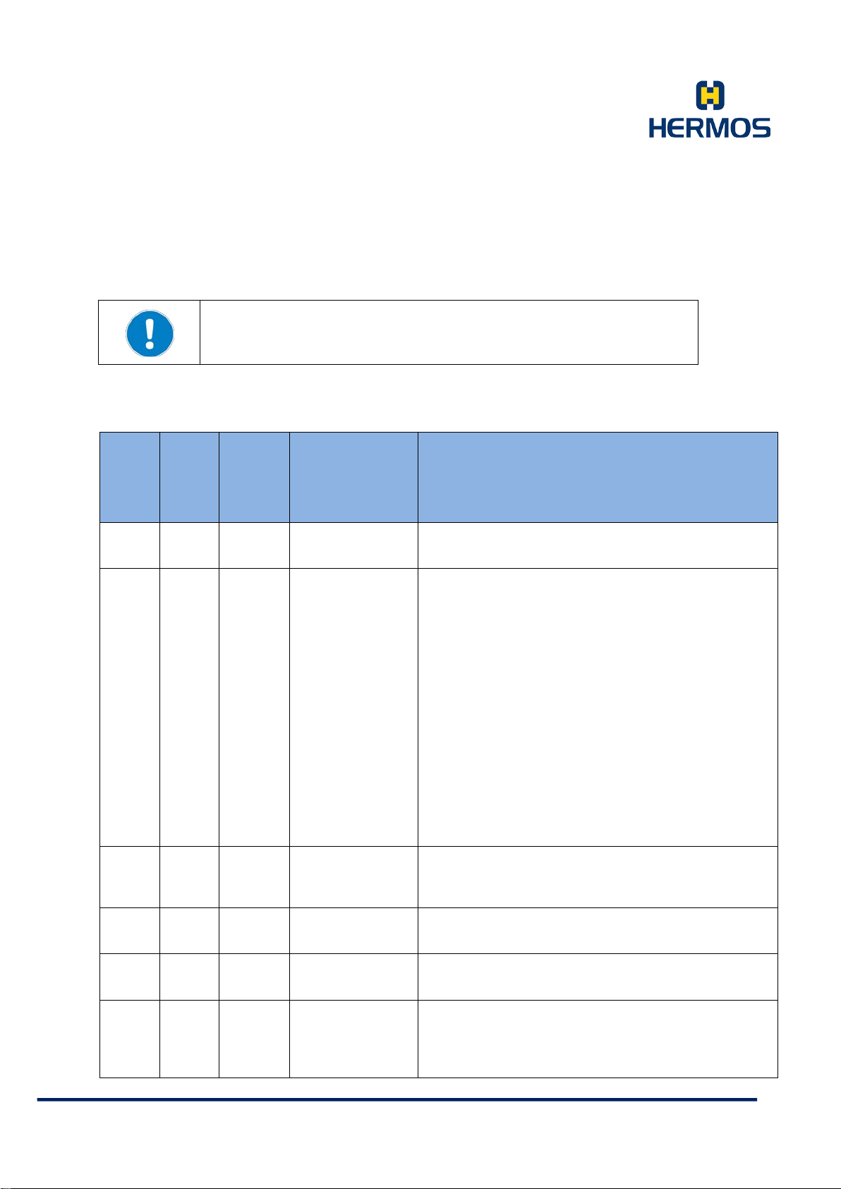
Product Manual
Delay time for the presence s ensor.
Standard: 10 … (1 second )
Read mode for readin g automatically started by
Standard: 00 … ( read only one page )
Page for readmode "00".
Standard: 00 … (read first page)
Time between two read/write attempts.
Standard: 05 … (0,5 seconds)
Max. number of read/write attempts.
Standard: 05
If no confirmation message has been received from
('RS232 max repeat').
Customer Documentation
Version 1.0
LFP Handhe ld Ke yb oar demul ati on 07.06.2018
Page 61 of 75
7.4.5 Parameters
When using the “G” command, only some of the public parameters are
retrieved!
The data element "Parameter No." can have the following values. The following list contains the public
param eters of th e ASC-I1 prot oco l:
“G“
No.
(dec)
No.
(hex)
Comm
and
Suppo
rt
Parameter
Name
Description
0 0x00 Yes
1 0x01 Yes
2 0x02 Yes
3 0x03 Yes
Sensor Delay
Read Mode
Read Page
r/w Repeat Time
01 .. 99 (0.1 seconds)
external input.
00 - read only one page
01 - read to end character or empty character2)
02 - read all pages
10 - read only one page with prev iou s s ensor Check1)
11 - read to end character/empty character with
previous sensor check 1) 2)
12 - read all pages with previous sensor check1)
99 - Deactivate sensor
1) If sensor check is activated (first byte = 1), the
assignment of the read button is c hecked before
initiating a read/ write operation.
If this is not the case, the "NOTAG" error message is
sent.
2) 'E' or 'F' in ID Bit 0...3 of the read ID
00 - First page of each transponder
01 .. 17 - Page of a multi-page tr a nsponder
01 .. 99 (0,1 s)
4 0x04 Yes
5 0x05 Yes
HERMOS AG
Gartenstra s se 19 Tel. +49(9279) 991-0
D-95490 M istelgau Fax. +49(9279) 991-100
r/w Max Repeat
RS232 Repeat
Time
01 .. 99
the host, the device waits for this time before sending
a message again.
The number of repetitions is defined in parameter 6
Page 62

Product Manual
01 .. 99 (0,1 s)
Standard: 45 … (4,5 seconds)
Customer Documentation
Version 1.0
LFP Handhe ld Ke yb oar demul ati on 07.06.2018
Page 62 of 75
HERMOS AG
Gartenstra s se 19 Tel. +49(9279) 991-0
D-95490 M istelgau Fax. +49(9279) 991-100
Page 63

Product Manual
The reader repeats the mess a ge a c c or din g to th e
Standard: 3
Bit0 (0x01): Activates/ deactivates the event
Standard: 0x1C
Transponder charging time in millise conds.
Standard: 32(50ms)
Polarity of all sensors
Standard: 00
ReaderID (0 ... E)
Standard: 0
This time defines the bounce time for pressing the
Standard: 0x01 (100ms)
This time defines the bounce time for releasing the
Standard: 0x01 (100ms)
Bit0 (0x01): Read button is a c tiv a ted/ deactivated
Customer Documentation
Version 1.0
LFP Handhe ld Ke yb oar demul ati on 07.06.2018
Page 63 of 75
value of this parameter if the host does not send the
expected confirmation message.
Then an error message is sen t.
00 - Endless
01 .. 99 - Number of attempts
message to the host th a t button has been enabled.
Default: 0 (deactivated)
Bit1 (0x02): Activates/ deactivates the event
message to the host th at the button ha s been
pressed.
Default: 0 (deactivated)
Bit2 (0x04): Activates/ deactivates automatic reading
triggered by read button
Default: 1 (activated)
Bit3 (0x08): A confirmatio n message is expected on
sensor messages A and B.
Default: 1 (confirmation expec ted )
Bit4 (0x10): A confirmatio n message is expected on
the message of automatic read R.
Default: 1 (confirmation expec ted)
6 0x06 Yes
7 0x07 Yes
RS232 Max
Repeat
Watch Port
9 0x09 No
14 0x0E No
15 0x0F Yes
18 0x12 No
19 0x13 No
20 0x14 No
HERMOS AG
Gartenstra s se 19 Tel. +49(9279) 991-0
D-95490 M istelgau Fax. +49(9279) 991-100
Transponder
Charging Time
Sensor Polarity
Reader Address
Bounce Time
Button Off
Bounce Time
Button On
Button Activity
Range: 00-FF
00 - Identification
01 - Interruption
button.
00 .. 255 (0,1 s)
button.
00 .. 255 (0,1 s)
Standard: 1 (activated)
Bit1 (0x02): Set bu tton is activated/ deactivated
Standard: 1 (activated)
Page 64

Product Manual
Bit2 (0x04): Menu button is activated/ deactivated
Standard parameter value : 0x07 (all 3 buttons active)
Customer Documentation
Version 1.0
LFP Handhe ld Ke yb oar demul ati on 07.06.2018
Page 64 of 75
Standard: 1 (activated)
HERMOS AG
Gartenstra s se 19 Tel. +49(9279) 991-0
D-95490 M istelgau Fax. +49(9279) 991-100
Page 65

Product Manual
Defines the behaviour of th e s ignal buzzer and the
Standard Parameter Valuet: 0x3F
The keyboard is subjected to a short self-test during
Standard: 0x01
Time between 2 readings when the device is in polling
1..255 Poll time in 100ms c ycle
Bit0 .. Bit3 (0x00 to 0x0F): T he lower 4 nibbles of the
of the K message.
Customer Documentation
Version 1.0
LFP Handhe ld Ke yb oar demul ati on 07.06.2018
Page 65 of 75
status LED during automatic reading and polling
Bit0 (0x01): If the reading is successful in polling
mode, the buzzer is briefly switched on if the tag is
newly recognized.
Standard: 1 (activated)
Bit1 (0x02): The s ta tus LED is briefly sw itched on
after success ful reading in pollin g m ode
Standard: 1 (activated)
Bit2 (0x04): If reading is suc c es s ful in polling mode,
36 0x24 No
LED Setup
the buzzer is br iefly switched on if the transponder is
already reported.
Standard: 1 (activated)
Bit4 (0x10): The buzz er is briefly s witched on after
successful automatic reading
Standard: 1 (activated)
Bit5 (0x20): The s ta tus LED is briefly sw itched on
after successful automatic reading.
Standard: 1 (activated)
38 0x26 No
39 0x27 No
40 0x28 No
Keyboard Test
Polling
Frequency
Polling Mode
the reset process. The log type is a ls o displayed.
00 - Keyboard test deactiva ted
01 - Keyboard test activat ed
mode.
0 Polling deactivated
poll mode determine wheth er a K -m e s sage without
data is to be sent with each read attempt if no
transponder was read.
00 - Send K message
01 - no K message
02 - Send K-message only once
Standard: 1 (No K message without da ta)
Bit4 (0x10):
Standard: 1 (Polling act ivated)
Bit6 (0x40): If bit6 is set, a K message is only output
if the tag was read for the first time. If bit 6 is
deleted, a K message is sent with each successful
reading
Standard: 1 (Send K messag e once)
Bit7 (0x80): Activates or deactivates the acknowledge
Activates or deactivat es p olling
HERMOS AG
Gartenstra s se 19 Tel. +49(9279) 991-0
D-95490 M istelgau Fax. +49(9279) 991-100
Page 66

Product Manual
Standard: 1 (Acknowledge e xpected)
Standard Parameter Value: 0xD1
Defines the page to be read durin g polling.
Standard: 0x00
Defines the number of read cy c les how often a
Standard: 0x01
Defines the number of read cy c les that a transponder
Standard: 0x03
This parameter determines the mode in which the
Standard: „00“
This read-only parameter can only be read out and
Standard: „SW_LFSH_1. x_yz“ x and yz are variable
This read-only parameter can only be read out and
variable
This read-only parameter can only be read out and
"A" defines the hardware r evision
Depending on the set customer mod e ( pa r . 0x40), the
Standard: „00“
Customer Documentation
Version 1.0
LFP Handhe ld Ke yb oar demul ati on 07.06.2018
Page 66 of 75
00 - read all transponder ty pes ( pa ge 1)
41 0x29 No
42 0x2A No
43 0x2B No
64 0x40 No
Polling Page
Polling Verify
Polling Fallout
Custom er M ode
01 ... 17 - the specified page of a multipage
transponder
transponder must be read until it is considered
recognized.
been converted.
01 .. 255
that has already been read m ust not be read until it is
considered to have been removed.
01 .. 255
reader is operated. Default pa r a m eter s a re a ls o
created when the customer m ode is s et.
0x00 - Protocol standard ASC-I1
0x03 - Protocol AS C-W1
0x10 - Keyboard emu lation with cus tom e r 0 s ettings
0x11 - Keyboard emu lation with cus tom e r 1 s ettings
0x12 - Keyboard emu lation with cus tom e r 2 s ettings
Evaluation of the parameter has not yet
70 0x46 No
71 0x47 No
72 0x48 No
96 0x60 No
HERMOS AG
Gartenstra s se 19 Tel. +49(9279) 991-0
D-95490 M istelgau Fax. +49(9279) 991-100
Software
Version
Serial Number
Hardware
Version
Default
Parameter
supplies the comp lete software version as an ASCII
string.
returns the provided 12-digit serial number as an
ASCII string.
Standard: „abcdHAGvwxyz“ abcd and vwxyz are
returns the hardware version as an ASCII string.
Standard: „LFS_HLG_RevA“
corresponding default values are created via this
parameter. The query of the par a m eter is provided by
the software fine version.
0x00 - Create default values
Page 67

Product Manual
Parameter has no further function.
Default: 1
Polling Readfactor
Parameter has no further function.
Default: 0
Customer Documentation
Version 1.0
LFP Handhe ld Ke yb oar demul ati on 07.06.2018
Page 67 of 75
For the ASC-W1 mode, the following parameters either have a different meaning or are additional
parameters:
No.
(dec)
8 0x8
No.
(hex)
Parameter Name Description
Parameter8
Range: 00-01
9 0x9
10 0xA
11 0xB
12 0xC
13 0xD
Transponder Charging Time
Polling Verify
Polling Fallout
Parameter13
Analog parameter 29 standa r d A SCI-I1
Analog parameter 42 standa r d A SCI-I1
Analog parameter 43 standa r d A SCI-I1
Analog parameter 39 standa r d A SCI-I1
Range: 00-FF
HERMOS AG
Gartenstra s se 19 Tel. +49(9279) 991-0
D-95490 M istelgau Fax. +49(9279) 991-100
Page 68

Product Manual
Customer Documentation
Version 1.0
LFP Handhe ld Ke yb oar demul ati on 07.06.2018
Page 68 of 75
7.4.6 Message Examples
ASCII HEX Description
‚S' 53
‚0‘ 30
‚2‘ 32
‚H‘ 48
‚0‘ 30
CR 0D
‚2‘ 32
‚4‘ 34
‚3‘ 33
‚A‘ 41
Start character
High byte message length
Lowbyte message length
Message first ch arac ter: value
Message second character: destination address
End character
Highbyte – Checksum XOR
Lowbyte – Checksum XOR
Highbyte – Checksum Addition
Lowbyte – Checksum Addition
Calculation of the XOR checksum:
53 XOR 30 XOR 32 XOR 48 XOR 30 XOR 0D = 24 '2' '4'
Calculation of the addition checksum:
53 + 30 + 32 + 48 + 30 + 0D = 13A '3' 'A'
(LSB is us ed)
HERMOS AG
Gartenstra s se 19 Tel. +49(9279) 991-0
D-95490 M istelgau Fax. +49(9279) 991-100
Page 69

Product Manual
Customer Documentation
Version 1.0
LFP Handhe ld Ke yb oar demul ati on 07.06.2018
Page 69 of 75
The following examples are based on the standard ASC-I1 pro toc ol:
V – Query Software Version
>> V0
<< v04C46534849312E30
Command V
Reader-ID 1
Software Version '4C46534849312E30‘ ASCII "LFSHI1.0"
X - Read data (R eadin g fro m p age 1 of the multip age t ranspo nde r)
>> X001
<< x0013132333435363738
Command X
Reader-ID 1
Page 01
Data '4142434445464748' ASCII "ABCDEFGH"
R – Automat ic R ead ing
<< R1013132333435363738
>> r1
Command R
Reader-ID 1
Page 01
Data '3132333435363738' ASCII "12345678"
W – Write Data (Write Page 17 of the multipage tran sponde r)
>> W0173137333435363738
<< w0
Command W
Reader-ID 0
Page 17 (decimal!!)
Data '3137333435363738' ASCII "12345678"
P – Set Parameter 0x27
<< P0270A
>> p0
Command P
Reader-ID 0
Parameter 27 (2-digit hexadecimal)
Parameter Value 0A (2-digit hexadecimal)
F – Query Parameter 0x27
<< F027
>> f0270A
Command F
Reader-ID 0
Parameter 27 (2-digit hexadecimal)
HERMOS AG
Gartenstra s se 19 Tel. +49(9279) 991-0
D-95490 M istelgau Fax. +49(9279) 991-100
Page 70
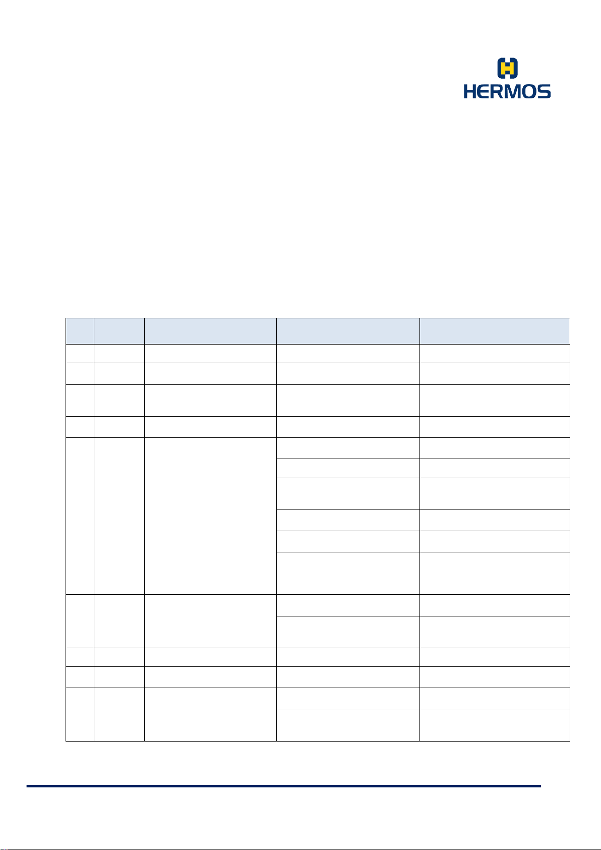
Product Manual
Automatic reading is not
possible
Reader still processes p revious
read or write requests
Wait until previous request is
completed
Action started from host
reading or writing)
Data transmission to the
transponder is not possi ble.
Reader still processes p revious
read or write requests
Wait until previous request is
completed
Antenna is not connecte d
correctly
Move the transponder into the
and function of the trans ponder
Antenna / transponders a re
misaligned
Check alignment of antenna an d
transponder
Antenna is damaged or too
close to metal
Check the antenna envi ronment
motors,...)
Data sent with a command is
wrong
Check command syntax and data
content
Transmission parameters a re
range
The device is not yet
configured
Incorrect reader address is
transmitted
Check message syntax, ch eck
parameter F "Reader address
Check the baud rate of the serial
interface (Com-Port)
Check the RS232 cable an d
interference with RS232
Customer Documentation
Version 1.0
LFP Handhe ld Ke yb oar demul ati on 07.06.2018
Page 70 of 75
K – Polling Reading
<< K0013132333435363738
>> k0
Command K
Reader-ID 0
Page 01
Data '3132333435363738' ASCII "12345678“
7.4.7 Error Codes
ID Name Description Possible Cause R emedia l Action
0 none No error none
1 auto fail
2 ext fail
3 write fail
4 no tag
5 invalid
6 unknown unkno wn fault none
7 Unconfig
cannot be executed. (e.g.
No transponder or antenna
installed
unknown parame ter or
unknown data
Reader still processes p revious
read or write requests
Antenna is not tuned Perform antenna tuning
No readable transponder within
the reading range
Interference field at
transmission frequency
not implemented or out of
Wait until previous request is
completed
Check antenna connection
antenna area. Check the type
Replace antenna, check t uning
for possible sources of
interference. (mo nitors, ser vo
Check parameter syntax and
value
8 check Parity and/or check sum error
HERMOS AG
Gartenstra s se 19 Tel. +49(9279) 991-0
D-95490 M istelgau Fax. +49(9279) 991-100
Wrong baud rate is set
Transmission error with
serial communication
connector, check sources of
Page 71

Product Manual
Check the RS232 cable an d
interference with RS232
Check Ethernet cable and
settings
Double or false
acknowledgement
Check communication settings
on the host
Locked side cannot be
written
Page to be written is
permanently write-protected
Check page number to be
written, replace tag with new one
Maximum number of trans-
specified time f rame
Check availability of host system,
An incorrect transponder type
Multipage)
Message length is longer than
length byte
Messages are displayed
longer than in the length byte
Check message length, check
length byte
Not all characters are transmitted (Intercharacter timeou t)
Check message syntax, check
RS232 or Ethernet connection
Customer Documentation
Version 1.0
LFP Handhe ld Ke yb oar demul ati on 07.06.2018
Page 71 of 75
9 void ackn
A Locked
B No ackn
No valid acknowledgement
(unexpected acknowledge)
missions of the message to
be acknowledged has
occurred (RS232
maxrepeat), the t erminal d id
not confirm within the
Serial communication
is interrupted
Ethernet communication
is interrupted
Host system does not
acknowledge the message
connector, check sources of
connector, check IP add ress
check RS232 cables and
connectors, check Ethernet
cables and connectors, check IP
address settings
C Bad type Wrong transponder type
Message too long or too
: Msg len
; Invalid I nvalid comm and Unkno wn command was sent Check message s yntax
short or message is not
received completely
is used (Read only or
Read/Write instead of
Message too long or too short
or message is not recei ved
completely
Check and replace transponder
type
displayed on the length byte
Check message length and
HERMOS AG
Gartenstra s se 19 Tel. +49(9279) 991-0
D-95490 M istelgau Fax. +49(9279) 991-100
Page 72
Product Manual
Customer Documentation
Version 1.0
LFP Handhe ld Ke yb oar demul ati on 07.06.2018
Page 72 of 75
8. Service and Troubleshooting
8.1 General Information
Follow the basi c s afety instructions in the chapter safety
instructions.
The maintenance of the reading device and its components may only be
performed by the manufacturer
Observe the instructions in this section when errors occur. Do not perform any
further troubleshooting measures in addition to the des cribed measures.
In case o f doubt concerning errors and handling the m, contact the manufacturer.
8.2 Troubleshooting Personnel
Troubleshooting must onl y be perf ormed by sp ecially t rained
personnel.
In case of doubts concerning the necessary qualifications,
contact the manufacturer.
The handling of device errors by untrained personnel as well as
the incorrect handling of the device can result in personal
injuries as well as damages to the reading device and/or
connected devices.
HERMOS AG
Gartenstra s se 19 Tel. +49(9279) 991-0
D-95490 M istelgau Fax. +49(9279) 991-100
Page 73
Product Manual
Customer Documentation
Version 1.0
LFP Handhe ld Ke yb oar demul ati on 07.06.2018
Page 73 of 75
8.3 Safety Instructions
All components of the antenna oscillating circuit carry high
voltage.
Only use spare parts specified by the manufacturer.
Unauthorised su bstitutio n of parts c an result in fire, elect ric
shock or other hazards.
Electrostatic charges damage electronic components within the
device.
ESD protective measures must be applied before op ening the
device.
Carefully remove the housing covers t o preven t damag e. Do
not operate the device when the housing is open.
Never short circuit the fuse! This may result in fire or damag es
on the device.
Only use fuses specified by the manufacturer.
HERMOS AG
Gartenstra s se 19 Tel. +49(9279) 991-0
D-95490 M istelgau Fax. +49(9279) 991-100
Page 74
Product Manual
Customer Documentation
Version 1.0
LFP Handhe ld Ke yb oar demul ati on 07.06.2018
Page 74 of 75
8.4 Software Releases
Release Date Version Description
June 2018 LFSHI1.0 Initial release
8.5 Customer Serv ice
HERMOS AG
Track & Trace RFID Division
Gartenstraße 19
D-95490 Mistelgau
Deutschland
HERMOS AG
Gartenstra s se 19 Tel. +49(9279) 991-0
D-95490 M istelgau Fax. +49(9279) 991-100
Page 75
Product Manual
Dispose of the materials separately and according to the legal
Customer Documentation
Version 1.0
LFP Handhe ld Ke yb oar demul ati on 07.06.2018
Page 75 of 75
9. Disassembly and Storage
9.1 Disassembly
To disassemble, remove the cable from the USB port.
9.2 Storage
Store the reading device and its components in a clean and dry environment.
Make sure that the power supply has been removed.
Observe the required storage conditions specified in the technical data.
10. Transport and Disposal
10.1 Transport
Use a solid cardboard box for the transport.
Use enough cushioning material to protect the device on all sides.
10.2 Disposal
The device and its components are made of various materials.
Disconnect the electronic components from the housing and attachments and dispose of them separately.
Do not dispose of the unit in normal domestic waste.
regulations of your country.
Housing and attachments as plastic waste
Electronic components, ant ennas and cables as electronic waste
HERMOS AG
Gartenstra s se 19 Tel. +49(9279) 991-0
D-95490 M istelgau Fax. +49(9279) 991-100
 Loading...