

HERKULES HSG 150 Instruction Manual
Art.-Nr.: 15.749.71 I.-Nr.: 01018
HSG
150
Bedienungsanleitung
Schutzgas-Schweißgerät
Instruction manual
Shielding Gas Welder
Mode dʼemploi
Appareil à souder au gaz inerte
Manual de instrucciones
Soldador en atmósfera protectora
Istruzioni per lʼuso
Saldatrice a gas inerte
Betjeningsvejledning
Beskyttelsesgas-svejseapparat
Bruksanvisning
MIG/MAG-svets
q
Käyttöohje
Suojakaasuhitsauslaite
Használati utasítás
Védőgáz-hegesztőkészülék
B
Upute za uporabu
Uređaj za zavarivanje sa zaštitnim plinom
j
Návod k obsluze
Svářečka pro svařování v ochranné
atmosféře
X
Navodila za uporabo
Varilni aparat na zaščitni plin
Kullanma Talimat∂
Gazaltı Kaynak Makinesi
L
Bruksanvisning
Sveiseapparat for dekkgass
E
Notandaleiðbeiningar
MIG-MAG suðutæki
H
Metināšanas aparāta
Aizsarggāzes metināšanas ierīce
Anleitung_HSG_150_SPK7:_ 11.06.2008 15:17 Uhr Seite 1

2
Vor Inbetriebnahme Bedienungsanleitung und
Sicherheitshinweise lesen und beachten
Read and follow the operating instructions and safety information
before using for the first time.
Avant la mise en service, lisez le mode dʼemploi et les consignes
de sécurité et respectez-les.
Leer detenidamente las instrucciones de uso y las advertencias de
seguridad antes de poner en marcha el aparato.
Prima della messa in esercizio leggete e osservate le istruzioni
per lʼuso e le avvertenze di sicurezza.
Betjeningsvejledningen og sikkerhedsanvisningerne skal læses,
inden maskinen tages i brug. Alle anvisninger skal følges.
Läs igenom och beakta bruksanvisningen och säkerhetsanvisningarna
före användning.
q Lue käyttöohje ja turvallisuusmääräykset ennen käyttöönottoa ja
noudata niitä.
Üzembehelyezés előtt elolvasni és figyelembe venni a használati
utasítást és a biztonsági utasításokat.
B Prije puštanja u rad pročitajte i pridržavajte se ovih uputa za uporabu
i sigurnosnih napomena.
j Před uvedením do provozu si přečíst návod k obsluze a bezpečnostní
předpisy a oboje dodržovat.
X Pred uporabo preberite in upoštevajte navodila za uporabo in
varnostne napotke.
Aleti çal∂μt∂rmadan önce Kullanma Talimat∂n∂ ve Güvenlik Uyar∂lar∂n∂
okuyun ve riayet edin.
Les bruksanvisningen nøye før montering og oppstart.
E Vinsamlegast lesi› notkunarlei›beiningarnar vandlega fyrir
uppsetningu og notkun saganna
H Pirms ekspluatācijas sākšanas izlasiet un ievērojiet lietošanas
instrukciju un drošības norādījumus.
Anleitung_HSG_150_SPK7:_ 11.06.2008 15:18 Uhr Seite 2
3
1
2
1
4
6
12
13
2
3
14
8
16
3
18
19
8
6
1
17
5
15
10
9
7
11
5
Anleitung_HSG_150_SPK7:_ 11.06.2008 15:18 Uhr Seite 3
4
7
4
6
8
5
9
24
a
b
c
d
e
f
g
h
i
j
S
23
22
25
12
13
20
19
12
26
21
q
p
o
n
m
8
6
l
k
r
Anleitung_HSG_150_SPK7:_ 11.06.2008 15:18 Uhr Seite 4
5
10
12
11
13
a
b
c
g
h
i
14
15
m
k
l
d, e, f
6
8
1
Anleitung_HSG_150_SPK7:_ 11.06.2008 15:18 Uhr Seite 5
6
17
19
20
16
p
p
p
21
o
o
o
r
p
18
1.
4.
2.
3.
q
q
n
n
q
S
S
k, l, m
Anleitung_HSG_150_SPK7:_ 11.06.2008 15:18 Uhr Seite 6
7
22
24
23
25
A
15
1.
2.
5
15
A
B
C
26
27
B
C
19
J
18
23
19
J
18
16
Anleitung_HSG_150_SPK7:_ 11.06.2008 15:18 Uhr Seite 7
8
31
H
32
I
29
A
K
B
N
J
30
1.
2.
28
A
N
H
G
G
F
E
D
L
I
M
D
B
C
1.
2.
Anleitung_HSG_150_SPK7:_ 11.06.2008 15:18 Uhr Seite 8
9
35
F
G
D
36
F
L
E
33
L
34
H
M
L
E
2.
1.
Anleitung_HSG_150_SPK7:_ 11.06.2008 15:18 Uhr Seite 9

10
D
Inhaltsverzeichnis: Seite
1. Sicherheitshinweise 11
2. Gerätebeschreibung und Lieferumfang 11
3. Bestimmungsgemäße Verwendung 11
4. Technische Daten 12
5. Vor Inbetriebnahme 13-14
6. Bedienung 14-15
7. Reinigung, Wartung und Ersatzteilbestellung 15
8. Entsorgung und Wiederverwertung 15
9. Störungssuche 16
10. Erklärung der Symbole 17
Anleitung_HSG_150_SPK7:_ 11.06.2008 15:18 Uhr Seite 10

11
D
Achtung!
Beim Benutzen von Geräten müssen einige
Sicherheitsvorkehrungen eingehalten werden, um
Verletzungen und Schäden zu verhindern. Lesen Sie
diese Bedienungsanleitung und die Sicherheitshinweise deshalb sorgfältig durch. Bewahren Sie
diese gut auf, damit Ihnen die Informationen jederzeit
zur Verfügung stehen. Falls Sie das Gerät an andere
Personen übergeben sollten, händigen Sie diese
Bedienungsanleitung/ Sicherheitshinweise bitte mit
aus. Wir übernehmen keine Haftung für Unfälle oder
Schäden, die durch Nichtbeachten dieser Anleitung
und der Sicherheitshinweise entstehen.
1. Sicherheitshinweise
Die entsprechenden Sicherheitshinweise finden Sie
im beiliegenden Heftchen!
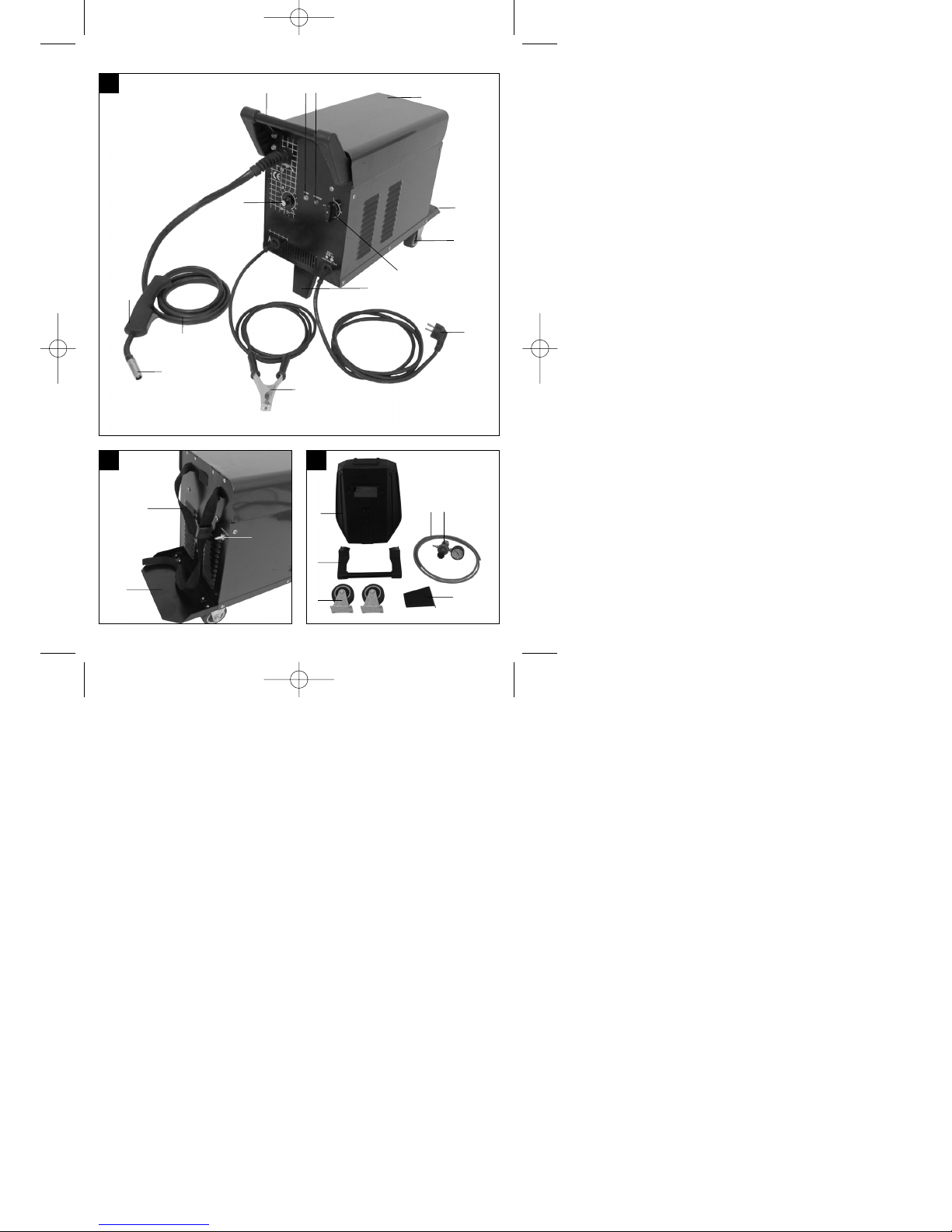
2. Gerätebeschreibung und
Lieferumfang (Bild 1-8)
1. Handgriff
2. Betriebsanzeige
3 Kontrollleuchte Thermowächter
4. Gehäuseabdeckung
5. Gasflaschen-Abstellfläche
6. Laufrollen
7. Ein-/Aus-/Schweißstrom-Schalter
8. Standfuß
9. Netzstecker
10. Masseklemme
11. Schlauchpaket
12. Gasdüse
13. Brenner
14. Schweißdraht-Geschwindigkeitsregler
15. Gurtband
16. Gaszuführungsanschluss
17. Schweißschirm
18. Schutzgasschlauch
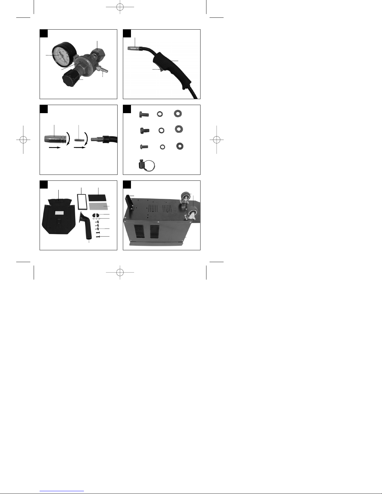
19. Druckminderer
20. Manometer
21. Verschraubung
22. Sicherheitsventil
23. Anschluss Schutzgasschlauch
24. Drehknopf
25. Brennerschalter
26. 2 x Kontaktrohr
2.1 Montagematerial
a. 8 x Schraube für Laufrollen
b. 8 x Sprengring für Laufrollen
c. 8 x Unterlegscheibe für Laufrollen
d. 4 x Schraube für Handgriff
e. 4 x Sprengring für Handgriff
f. 4 x Unterlegscheibe für Handgriff
g. 2 x Schraube für Standfuß
h. 2 x Sprengring für Standfuß
i. 2 x Unterlegscheibe für Standfuß
j. 2 x Schlauchklemme
k. 1 x Rahmen Schutzglas
l. 1 x Schweißglas
m. 1 x Transparentes Schutzglas
n. 2 x Haltebuchsen Schutzglas
o. 3 x Mutter für Haltegriff
p. 3 x Schrauben für Haltegriff
q. 2 x Haltestift Schutzglas
r. 1 x Handgriff
s. 1 x Schweißschirm-Rahmen
3. Bestimmungsgemäße Verwendung
Das Schutzgasschweißgerät ist ausschließlich zum
Schweißen von Aluminium im MIG-(Metall-InertGas)-Verfahren und Stählen im MAG-(Metall-AktivGas)-Verfahren unter Verwendung der
Entsprechenden Schweißdrähte und Gase geeignet.
Die Maschine darf nur nach ihrer Bestimmung
verwendet werden. Jede weitere darüber
hinausgehende Verwendung ist nicht
bestimmungsgemäß. Für daraus hervorgerufene
Schäden oder Verletzungen aller Art haftet der
Benutzer/Bediener und nicht der Hersteller.
Bitte beachten Sie, dass unsere Geräte
bestimmungsgemäß nicht für den gewerblichen,
handwerklichen oder industriellen Einsatz konstruiert
wurden. Wir übernehmen keine Gewährleistung,
wenn das Gerät in Gewerbe-, Handwerks- oder
Industriebetrieben sowie bei gleichzusetzenden
Tätigkeiten eingesetzt wird.
Anleitung_HSG_150_SPK7:_ 11.06.2008 15:18 Uhr Seite 11

12
D
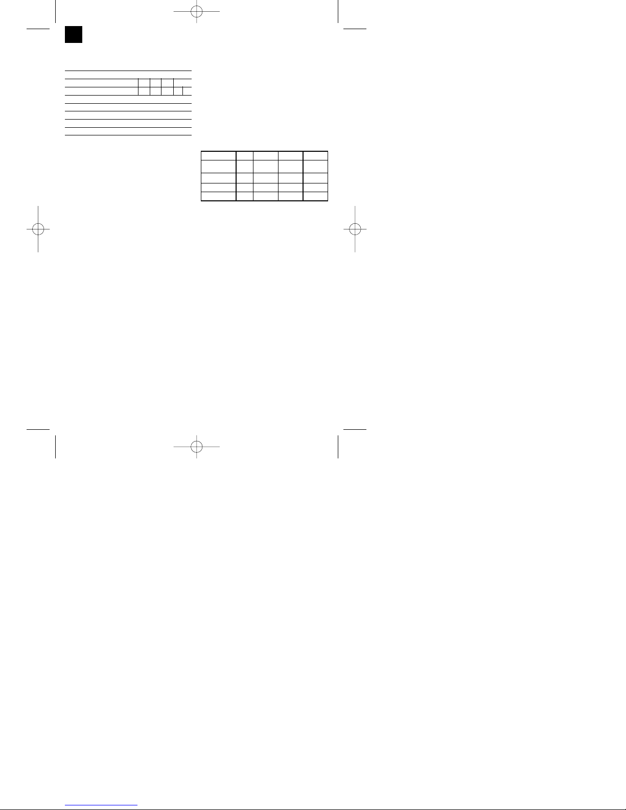
4. Technische Daten
Netzanschluss: 230 V ~ 50 Hz
Schweißstrom: 25-120 A (max. 150 A)
Einschaltdauer X%: 10 20 30 60 100
Schweißstrom I2(A): 120 90 75 52 40 25
Leerlaufstrom: 48 V
Schweißdrahttrommel max.: 5 kg
Schweißdrahtdurchmesser: 0,6/0,8 mm
Absicherung: 16 A
Gewicht: 25 kg
5. Vor Inbetriebnahme
5.1 Montage (Abb. 5-21)
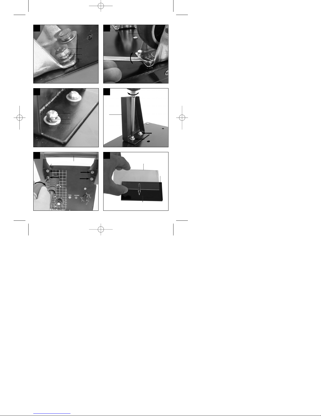
5.1.1 Montage der Laufrollen (6)
Laufrollen (6) wie in den Abbildungen 7, 9, 10, 11
dargestellt, montieren.
5.1.2 Montage des Standfußes (8)
Standfuß (8) wie in den Abbildungen 7, 9, 12, 13
dargestellt, montieren.
5.1.3 Montage des Handgriffes (1)
Handgriff (1) wie in den Abbildungen 7, 14
dargestellt, montieren.
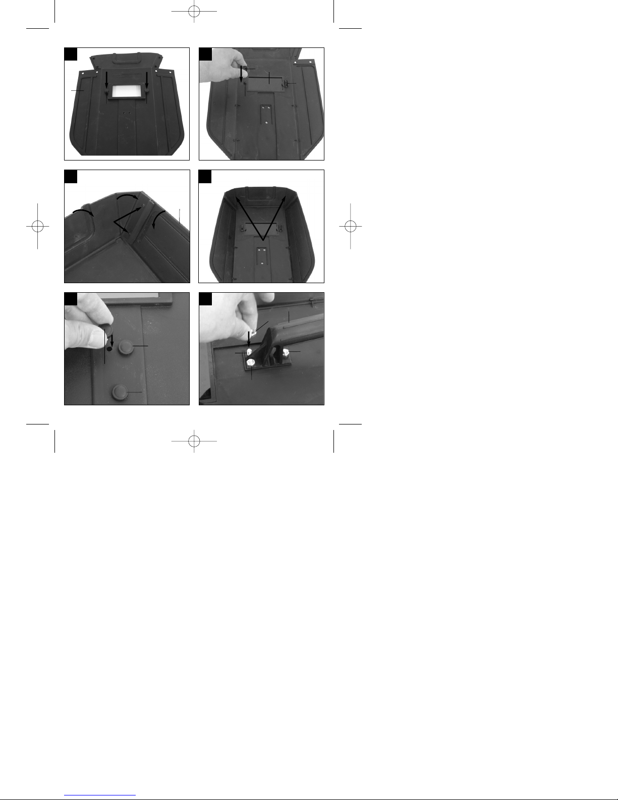
5.1.4 Montage des Schweißschirmes (17)
Schweißglas (l) und darüber transparentes
Schutzglas (m) in Rahmen für Schutzglas (k)
legen (Abb. 15).
Haltestifte Schutzglas (q) außen in Bohrungen im
Schweißschirm Rahmen (s) drücken. (Abb. 16)
Rahmen für Schutzglas (k) mit Schweißglas (l)
und transparentem Schutzglas (m) von innen in
die Aussparung im Schweißschirm-Rahmen (s)
legen, Haltebuchsen Schutzglas (n) auf
Haltestifte Schutzglas (q) drücken, bis diese
einrasten, um den Rahmen für Schutzglas (k) zu
sichern. Das transparente Schutzglas (m) muss
auf der Außenseite liegen. (Abb. 17)
Oberkante von Schweißschirm-Rahmen (s) nach
innen biegen (Abb. 18/1.) und Ecken der
Oberkante einknicken (Abb. 18/2.). Nun
Außenseiten des Schweißschirm-Rahmens (s)
nach innen biegen (Abb. 18/3.) und diese durch
festes Zusammendrücken der Oberkantenecken
und Außenseiten verbinden. Pro Seite müssen
beim Einrasten der Haltestifte 2 deutliche
Klickgeräusche wahrnehmbar sein (Abb. 18/4.)
Sind beide oberen Ecken des Schweißschirms,
wie in Abbildung 19 dargestellt, verbunden,
Schrauben für Haltegriff (p) von außen durch die
3 Löcher im Schweißschirm stecken. (Abb. 20)
Schweißschirm umdrehen und Handgriff (r) über
die Gewinde der 3 Schrauben für Haltegriff (p)
führen. Handgriff (r) mit den 3 Muttern für
Haltegriff (o) am Schweißschirm festschrauben.
(Abb. 21)
5.2 Gasanschluss (Abb. 4, 5, 22-27)
5.2.1 Gasarten
Beim Schweißen mit durchgehendem Draht ist
Gasschutz notwendig, die Zusammensetzung des
Schutzgases ist vom gewählten Schweißverfahren
abhängig:
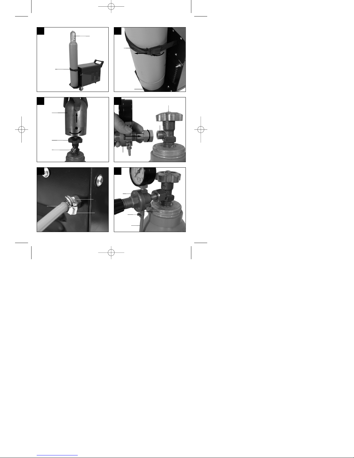
5.2.2 Gasflasche auf dem Gerät montieren
(Abb. 22-23)
Gasflasche ist nicht im Lieferumfang enthalten!
Montieren sie die Gasflasche wie in den Abbildungen
22-23 dargestellt. Achten Sie auf festen Sitz des
Gurtbandes (15) und darauf dass das Schweißgerät
kippsicher steht.
Achtung! Auf der Gasflaschen-Abstellfläche (Abb.
23/5) dürfen nur Gasflaschen bis maximal 10 Liter
montiert werden. Bei Verwendung größerer
Gasflaschen besteht Kippgefahr, diese dürfen daher
nur neben dem Gerät aufgestellt werden. Ist dies der
Fall muss die Gasflasche ausreichend gegen
Umkippen geschützt werden!
5.2.3 Anschluss der Gasflasche (Abb. 7, 24-27)
Nach dem Abnehmen der Schutzkappe (Abb. 24/A)
Flaschenventil (Abb. 24/B) in vom Körper
abgewandter Richtung kurz öffnen.
Anschlussgewinde (Abb. 24/C) gegebenenfalls mit
einem trockenen Lappen, ohne Zuhilfenahme
irgendwelcher Reinigungsmittel, von
Verschmutzungen reinigen. Kontrollieren ob
Dichtung am Druckminderer (19) vorhanden und in
einwandfreiem Zustand ist. Druckminderer (19) im
Uhrzeigersinn auf das Anschlussgewinde (Abb.
25/C) der Gasflasche schrauben (Abb. 25). Die
beiden Schlauchschellen (j) über den
Schutzgas CO2 Argon/CO2 Argon Argon/O
Zu schweißendes Metall
Unlegierter Stahl X X
Aluminium X
Edelstahl X X
Anleitung_HSG_150_SPK7:_ 11.06.2008 15:18 Uhr Seite 12

13
D
Schutzgasschlauch (18) führen. Schutzgasschlauch
(18) auf Anschluss Schutzgasschlauch (23) am
Druckminderer (19) und Gaszuführungsanschluss
(16) am Schweißgerät stecken und an beiden
Anschlussstellen mit den Schlauchschellen (j)
sichern. (Abb. 26-27)
Achtung! Achten Sie auf Dichtheit sämtlicher
Gasanschlüsse und Verbindungen! Kontrollieren Sie
die Anschlüsse und Verbindungsstellen mit
Leckspray oder Seifenwasser.
5.2.4 Erklärung des Druckminderers (Abb. 4/19)
Am Drehknopf (24) kann die Gasdurchflussmenge
eingestellt werden. Die eingestellte
Gasdurchflussmenge kann am Manometer (20) in
Litern pro Minute (l/min) abgelesen werden. Das Gas
tritt am Anschluss Schutzgasschlauch (23) aus und
wird über den Schutzgasschlauch (Abb. 3/18) zum
Schweißgerät weiterbefördert. (siehe 5.2.3)
Achtung! Verfahren Sie zum Einstellen der
Gasdurchflussmenge immer wie unter Punkt 6.1.3
beschrieben.
Der Druckminderer wird mit Hilfe der Verschraubung
(21) an der Gasflasche montiert (siehe 5.2.3).
Achtung! Eingriffe und Reparaturen am
Druckminderer dürfen nur von Fachpersonal
ausgeführt werden. Senden Sie defekte
Druckminderer gegebenenfalls an die
Serviceadresse.
5.3 Netzanschluss
Überzeugen Sie sich vor dem Anschließen, dass
die Daten auf dem Typenschild mit den
Netzdaten übereinstimmen.
Das Gerät darf nur an ordnungsgemäß
geerdeten und abgesicherten
Schutzkontaktsteckdosen betrieben werden.
5.4 Montage der Drahtspule (Abb. 1, 5, 6, 28 – 36)
Drahtspule ist nicht im Lieferumfang enthalten!
5.4.1 Drahtarten
Je nach Anwendungsfall werden verschiedene
Schweißdrähte benötigt. Das Schweißgerät kann mit
Schweißdrähten mit einem Durchmesser von 0,6 und
0,8mm verwendet werden. Die entsprechende
Vorschubrolle und Kontaktrohre liegen dem Gerät
bei. Vorschubrolle, Kontaktrohr und Drahtquerschnitt
müssen immer zusammen passen.
5.4.2 Drahtspulenkapazität
In dem Gerät können Drahtspulen bis maximal 5kg
montiert werden.
5.4.3 Einsetzen der Drahtspule
Gehäuseabdeckung (Abb. 1/4) öffnen
Kontrollieren dass sich die Wicklungen auf der
Spule nicht überlagern, um ein gleichmäßiges
Abwickeln des Drahtes zu gewährleisten.
Beschreibung der Drahtführungseinheit
(Abb. 28-30)
A Spulenarretierung
B Spulenhalter
C Mitnehmerstift
D Druckrollenhalter
E Druckrolle
F Justierschraube für Gegendruck
G Spannhebel
H Führungsrohr
I Vorschubrollenhalter
J Drahtspule
K Mitnahmeöffnung der Drahtspule
L Vorschubrolle
M Schlauchpaketaufnahme
N Justierschraube für Rollenbremse
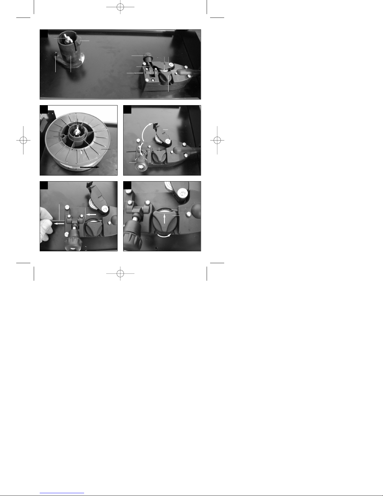
Einsetzen der Drahtspule (Abb. 28,29)
Drahtspule (J) auf Spulenhalter (B) legen. Darauf
achten dass das Ende des Schweißdrahtes auf der
Seite der Drahtführung abgewickelt wird, siehe Pfeil.
Beachten, dass die Spulenarretierung (A)
eingedrückt wird und der Mitnehmerstift (C) in der
Mitnahmeöffnung der Drahtspule (K) sitzt. Die
Spulenarretierung (A) muss wieder über der
Drahtspule (J) einrasten. (Abb. 29)
Einführen des Schweißdrahtes und justieren der
Drahtführung (Abb. 30-36)
Spannhebel (G) lösen, Druckrollenhalter (D)
hochklappen. (Abb. 30)
Führungsrohr (H) gegebenenfalls zurückziehen.
(siehe Markierung Abb. 31)
Vorschubrollenhalter (I) durch Linksdrehung aus
der Arretierung lösen und nach oben abnehmen.
(Abb. 32)
Vorschubrolle (L) überprüfen. Auf der oberen
Seite der Vorschubrolle (L) muss die
entsprechende Drahtstärke angegeben sein. Die
Vorschubrolle (L) ist mit 2 Führungsnuten
ausgestattet. Vorschubrolle (L) gegebenenfalls
umdrehen oder austauschen. (Abb. 33)
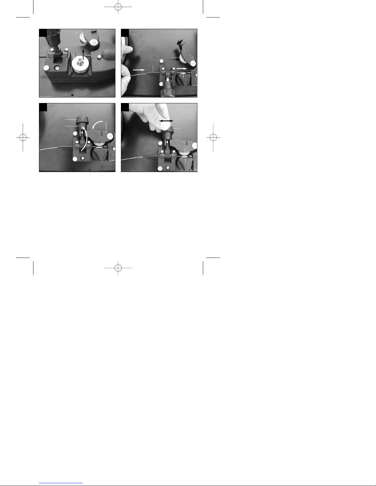
Vorschubrollenhalter (I) wieder aufsetzen und
durch Rechtsdrehung arretieren.
Führungsrohr (H) wieder so weit vorschieben,
dass es ca. 5mm von Druck- und Vorschubrolle
Anleitung_HSG_150_SPK7:_ 11.06.2008 15:18 Uhr Seite 13

14
D
(E/L) entfernt endet.
Gasdüse (Abb. 5/12) unter Rechtsdrehung vom
Brenner (Abb. 5/13) abziehen, Kontaktrohr (Abb.
6/26) abschrauben (Abb. 5 - 6). Schlauchpaket
(Abb. 1/11) möglichst gerade vom Schweißgerät
wegführend auf den Boden legen.
Die ersten 10 cm des Schweißdrahtes so
abschneiden, dass ein gerader Schnitt ohne
Vorsprünge, Verzug und Verschmutzungen
entsteht. Ende des Schweißdrahtes entgraten.
Schweißdraht durch das Führungsrohr (H),
zwischen Druck- und Vorschubrolle (E/L)
hindurch in die Schlauchpaketaufnahme (M)
schieben. (Abb. 34) Schweißdraht vorsichtig von
Hand so weit in das Schlauchpaket schieben bis
er am Brenner (Abb. 5/13) um ca. 1 cm
herausragt.
Justierschraube für Gegendruck (F) um einige
Umdrehungen lösen. (Abb. 36)
Druckrollenhalter (D) wieder nach unten klappen
und mit Spannhebel (G) arretieren. Lässt sich der
Spannhebel (G) nur schwer oder gar nicht
arretieren, muss die Justierschraube für
Gegendruck (F) weiter gelöst werden. (Abb. 35)
Justierschraube für Gegendruck (F) nun so
einstellen, dass der Schweißdraht fest zwischen
Druckrolle (E) und Vorschubrolle (L) sitzt ohne
gequetscht zu werden. (Abb. 36)
Passendes Kontaktrohr (Abb. 6/26) für den
verwendeten Schweißdrahtdurchmesser auf den
Brenner (Abb. 5/13) schrauben und Gasdüse
unter Rechtsdrehung (Abb. 5/12) aufstecken.
Justierschraube für Rollenbremse (N) so
einstellen, dass sich der Draht noch immer
führen lässt und die Rolle nach Abbremsen der
Drahtführung automatisch stoppt.
6. Bedienung
6.1 Einstellung
Da die Einstellung des Schweißgeräts je nach
Anwendungsfall unterschiedlich erfolgt, empfehlen
wir, die Einstellungen anhand einer
Probeschweißung vorzunehmen.
6.1.1 Einstellen des Schweißstromes
Der Schweißstrom kann in 6 Stufen am Ein-/Aus/Schweißstrom-Schalter (Abb. 1/7) eingestellt
werden. Der erforderliche Schweißstrom ist abhängig
von der Materialstärke, der gewünschten
Einbrenntiefe und dem verwendeten
Schweißdrahtdurchmesser.
6.1.2 Einstellen der DrahtvorschubGeschwindigkeit
Die Drahtvorschub-Geschwindigkeit wird automatisch
an die verwendete Stromeinstellung angepasst. Eine
Feineinstellung der Drahtvorschub-Geschwindigkeit
kann stufenlos am SchweißdrahtGeschwindigkeitsregler (Abb. 1/14) vorgenommen
werden. Es ist empfehlenswert bei der Einstellung in
Stufe 5 zu beginnen, welche einen Mittelwert
darstellt, und gegebenenfalls nachzuregeln. Die
erforderliche Drahtmenge ist abhängig von der
Materialdicke, der Einbrenntiefe, dem verwendeten
Schweißdrahtdurchmesser, und auch von der Größe
zu überbrückender Abstände der zu
verschweißenden Werkstücke.
6.1.3 Einstellen der Gasdurchflussmenge
Die Gasdurchflussmenge kann stufenlos am
Druckminderer (Abb.4/19) eingestellt werden. Sie
wird am Manometer (Abb. 4/20) in Liter pro Minute
(l/min) angegeben. Empfohlene Gasdurchflussmenge
in zugluftfreien Räumen: 5 – 15 l/min.
Zum Einstellen der Gasdurchflussmenge zuerst
Spannhebel (Abb. 28/G) der Drahtvorschub-Einheit
lösen, um unnötigen Drahtverschleiß zu vermeiden
(siehe 5.4.3). Netzanschluss herstellen (siehe Punkt
5.3), Ein-/Aus-/Schweißstrom-Schalter (Abb.1/7) auf
Stufe 1 stellen und Brennerschalter (Abb. 5/25)
betätigen, um Gasdurchfluss freizugeben. Nun am
Druckminderer (Abb. 4/19) gewünschte
Gasdurchflussmenge einstellen.
Linksdrehung des Drehknopfes (Abb. 4/24):
geringere Durchflussmenge
Rechtsdrehung des Drehknopfes (Abb. 4/24): höhere
Gasdurchflussmenge
Spannhebel (Abb. 28/G) der Drahtvorschub-Einheit
wieder festklemmen.
6.2 Elektrischer Anschluss
6.2.1 Netzanschluss
Siehe Punkt 5.3
6.2.2 Anschluss der Masseklemme (Abb. 1/10)
Masseklemme (10) des Gerätes möglichst in
unmittelbarer Nähe der Schweißstelle anklemmen.
Auf metallisch blanken Übergang an der
Kontaktstelle achten.
Anleitung_HSG_150_SPK7:_ 11.06.2008 15:18 Uhr Seite 14

15
D
6.3 Schweißen
Sind alle elektrischen Anschlüsse für
Stromversorgung und Schweißstromkreis sowie der
Schutzgasanschluss vorgenommen, kann
folgendermaßen verfahren werden:
Die zu schweißenden Werkstücke müssen im
Bereich der Schweißung frei von Farbe, metallischen
Überzügen, Schmutz, Rost, Fett und Feuchtigkeit
sein.
Stellen Sie Schweißstrom, Drahtvorschub und
Gasdurchflussmenge (siehe 6.1.1 – 6.1.3)
entsprechend ein.
Halten Sie den Schweißschirm (Abb. 3/17) vor das
Gesicht, und führen Sie die Gasdüse an die Stelle
des Werkstücks, an der geschweißt werden soll.
Betätigen Sie nun den Brennerschalter (Abb. 5/25).
Brennt der Lichtbogen, fördert das Gerät Draht in
das Schweißbad. Ist die Schweißlinse groß genug,
wird der Brenner langsam an der gewünschten
Kante entlang geführt. Gegebenenfalls leicht
pendeln, um das Schweißbad etwas zu vergrößern.
Die ideale Einstellung von Schweißstrom,
Drahtvorschub-Geschwindigkeit und
Gasdurchflussmenge anhand einer
Probeschweißung ermitteln. Im Idealfall ist ein
gleichmäßiges Schweißgeräusch zu hören. Die
Einbrenntiefe sollte möglichst tief sein, das
Schweißbad jedoch nicht durch das Werkstück
hindurch fallen.
6.4 Schutzeinrichtungen
6.4.1 Thermowächter
Das Schweißgerät ist mit einem Überhitzungsschutz
ausgestattet, welcher den Schweißtrafo vor
Überhitzung schützt. Sollte der Überhitzungsschutz
ansprechen, so leuchtet die Kontrolllampe (3) an
Ihrem Gerät. Lassen Sie das Schweißgerät einige
Zeit abkühlen.
7. Reinigung, Wartung und
Ersatzteilbestellung
Ziehen Sie vor allen Reinigungsarbeiten den
Netzstecker.
7.1 Reinigung
Halten Sie Schutzvorrichtungen, Luftschlitze und
Motorengehäuse so staub- und schmutzfrei wie
möglich. Reiben Sie das Gerät mit einem
sauberen Tuch ab oder blasen Sie es mit
Druckluft bei niedrigem Druck aus.
Wir empfehlen, dass Sie das Gerät direkt nach
jeder Benutzung reinigen.
Reinigen Sie das Gerät regelmäßig mit einem
feuchten Tuch und etwas Schmierseife.
Verwenden Sie keine Reinigungs- oder
Lösungsmittel; diese könnten die Kunststoffteile
des Gerätes angreifen. Achten Sie darauf, dass
kein Wasser in das Geräteinnere gelangen kann.
7.2 Wartung
Im Geräteinneren befinden sich keine weiteren zu
wartenden Teile.
7.3 Ersatzteilbestellung:
Bei der Ersatzteilbestellung sollten folgende
Angaben gemacht werden;
Typ des Gerätes
Artikelnummer des Gerätes
Ident-Nummer des Gerätes
Ersatzteilnummer des erforderlichen Ersatzteils
Aktuelle Preise und Infos finden Sie unter
www.isc-gmbh.info
8. Entsorgung und Wiederverwertung
Das Gerät befindet sich in einer Verpackung um
Transportschäden zu verhindern. Diese Verpackung
ist Rohstoff und ist somit wieder verwendbar oder
kann dem Rohstoffkreislauf zurückgeführt werden.
Das Gerät und dessen Zubehör bestehen aus
verschiedenen Materialien, wie z.B. Metall und
Kunststoffe. Führen Sie defekte Bauteile der
Sondermüllentsorgung zu. Fragen Sie im
Fachgeschäft oder in der Gemeindeverwaltung nach!
Anleitung_HSG_150_SPK7:_ 11.06.2008 15:18 Uhr Seite 15
16
D
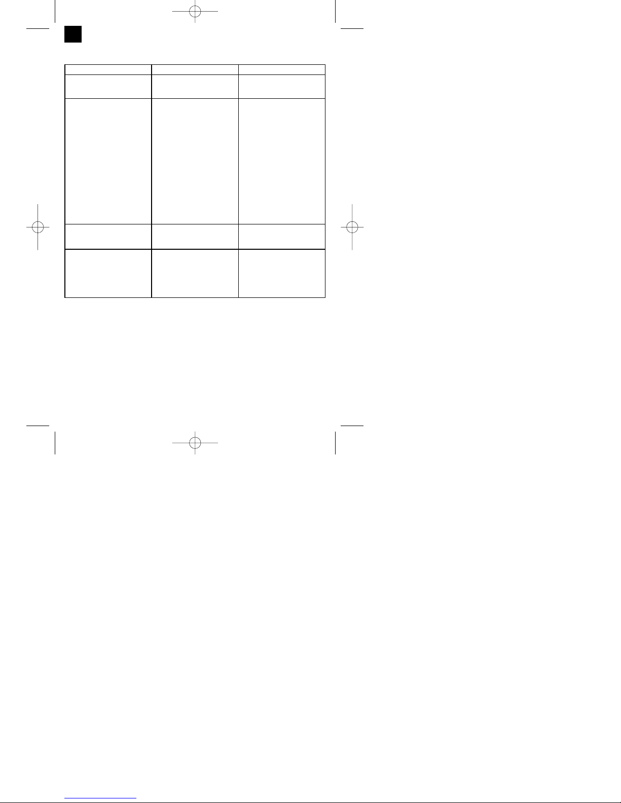
Fehler Ursache Abhilfe
Vorschubrolle dreht nicht Netzspannung fehlt
Regler Drahtvorschub auf 0
Anschluss überprüfen
Einstellung überprüfen
Vorschubrolle dreht, jedoch keine
Drahtzuführung
Schlechter Rollendruck
(siehe 5.4.3)
Rollenbremse zu fest eingestellt
(siehe 5.4.3)
Verschmutzte / beschädigte
Vorschubrolle (siehe 5.4.3)
Beschädigtes Schlauchpaket
Kontaktrohr falsche Größe /
verschmutzt / verschlissen
(siehe 5.4.3)
Schweißdraht an
Gasdüse/Kontaktrohr festgeschweißt
Einstellung überprüfen
Einstellung überprüfen
Reinigen bzw. austauschen
Mantel der Drahtführung
überprüfen
Reinigen / austauschen
lösen
Gerät funktioniert nach längerem
Betrieb nicht mehr, Kontrollleuchte
Thermowächter (3) leuchtet
Gerät hat sich durch zu lange
Anwendung bzw. Nichteinhaltung
der Rücksetzzeit überhitzt
Gerät mindestens 20-30 Minuten
abkühlen lassen
Sehr schlechte Schweißnaht Falsche Strom-/Vorschub-
einstellung
(siehe 6.1.1/6.1.2)
Kein / zu wenig Gas (siehe 6.1.3)
Einstellung überprüfen
Einstellung überprüfen bzw.
Fülldruck der Gasflasche
kontrollieren
9. Störungssuche
Anleitung_HSG_150_SPK7:_ 11.06.2008 15:18 Uhr Seite 16
17
D
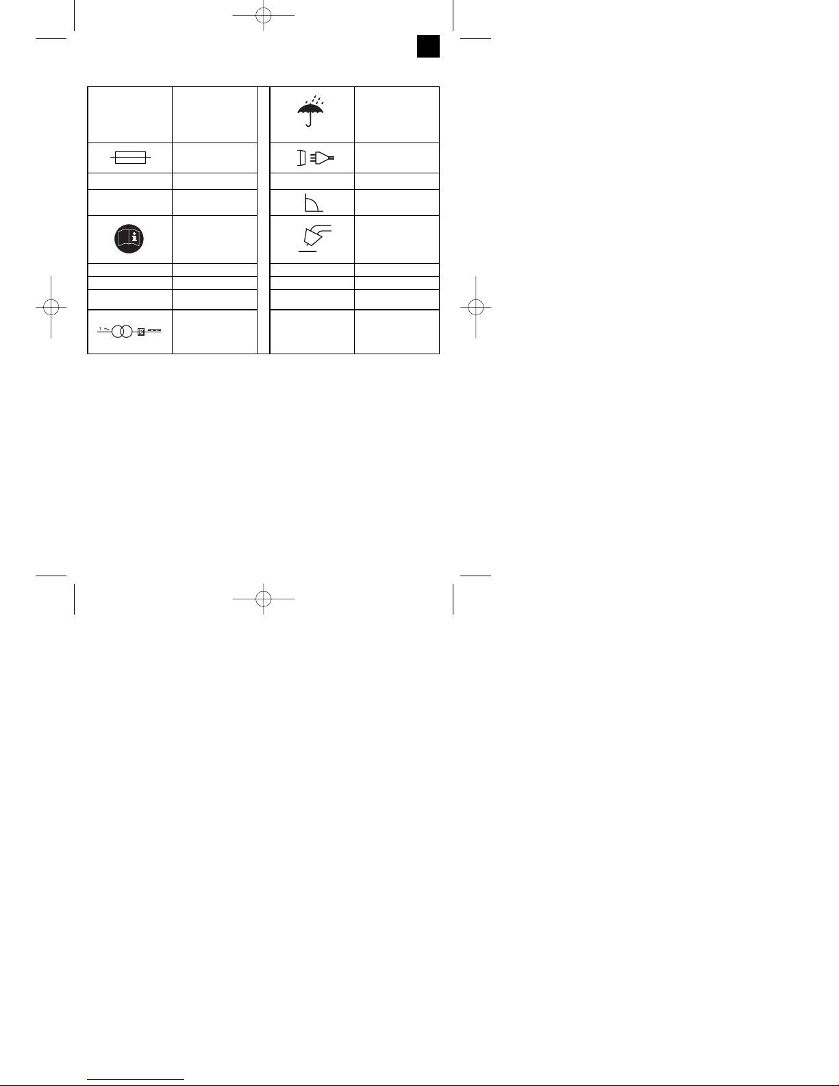
10. Erklärung der Symbole
EN 60974-1 Europäische Norm für
Lichtbogenschweißeinrichtungen und
Schweißstromquellen
mit beschränkter Einschaltdauer
Lagern oder verwenden
Sie das Gerät nicht in
feuchter oder nasser
Umgebung oder im
Regen
Sicherung mit Nennwert
in Ampere im
Netzanschluss
1 Phasen Netzanschluss
U
1
Netzspannung 50 Hz Netzfrequenz
I1max höchster Netzstrom
Bemessungswert
Symbol für fallende
Kennlinie
Vor Gebrauch des
Schweißgerätes die
Bedienungsanleitung
sorgfältig lesen und
beachten
Metall-Inert- und
Aktivgas-Schweißen
einschließlich der
Verwendung von
Fülldraht
U
0
Nennleerlaufspannung IP 21 Schutzart
I
2
Schweißstrom H Isolationsklasse
Ø mm Schweißdrahtdurch-
messer
X Einschaltdauer
Einphasiger
Transformator mit
Gleichrichter
Gerät ist funkentstört nach EG-Richtlinie 89/336/EWG
Anleitung_HSG_150_SPK7:_ 11.06.2008 15:18 Uhr Seite 17

Table of contents: Page
1. Safety regulations 19
2. Layout and items supplied 19
3. Intended use 19
4. Technical data 20
5. Before starting the equipment 20-22
6. Operation 22-23
7. Cleaning, maintenance and ordering spare parts 23
8. Disposal and recycling 23
9. Troubleshooting 24
10. Key to symbols 25
18
GB
Anleitung_HSG_150_SPK7:_ 11.06.2008 15:18 Uhr Seite 18

Important!
When using the equipment, a few safety precautions
must be observed to avoid injuries and damage.
Please read the complete operating instructions and
safety regulations with due care. Keep this manual in
a safe place, so that the information is available at all
times. If you give the equipment to any other person,
hand over these operating instructions and safety
regulations as well. We cannot accept any liability for
damage or accidents which arise due to a failure to
follow these instructions and the safety instructions.
1. Safety regulations
The corresponding safety information can be found
in the enclosed booklet.
2. Layout and items supplied (Fig. 1-8)
1. Handle
2. Operating status indicator
3. Thermostat control lamp
4. Housing cover
5. Gas bottle support surface
6. Castors
7. ON/OFF/Welding current switch
8. Supporting foot
9. Mains plug
10. Earth terminal
11. Hose package
12. Gas nozzle
13. Burner
14. Welding wire speed controller
15. Belt strap
16. Gas supply connector
17. Welding screen
18. Shielding gas hose
19. Pressure reducer
20. Pressure gauge
21. Screw connector
22. Safety valve
23. Shielding gas hose connector
24. Rotary knob
25. Burner switch
26. 2 x contact pipe
2.1 Assembly material
a. 8 x Screw for castors
b. 8 x Spring ring for castors
c. 8 x Washer for castors
d. 4 x Screw for handle
e. 4 x Spring ring for handle
f. 4 x Washer for handle
g. 2 x Screw for supporting foot
h. 2 x Spring ring for supporting foot
i. 2 x Washer for supporting foot
j. 2 x Hose clip
k. 1 x Safety glass frame
l. 1 x Welding glass
m. 1 x Transparent safety glass
n. 2 x Safety glass retaining bushes
o. 3 x Nut for handle
p. 3 x Screws for handle
q. 2 x Safety glass retaining pin
r. 1 x Handle
s. 1 x Welding screen frame
3. Intended use
The shielding gas welding set is exclusively designed
for welding aluminum with the MIG /metal inert gas)
method and steel with the MAG (metal active gas)
method using the appropriate welding wires and
gases.
The machine is to be used only for its prescribed
purpose. Any other use is deemed to be a case of
misuse. The user / operator and not the
manufacturer will be liable for any damage or injuries
of any kind caused as a result of this.
Please note that our equipment has not been
designed for use in commercial, trade or industrial
applications. Our warranty will be voided if the
machine is used in commercial, trade or industrial
businesses or for equivalent purposes.
19
GB
Anleitung_HSG_150_SPK7:_ 11.06.2008 15:18 Uhr Seite 19
4. Technical data
Mains connection: 230 V ~ 50 Hz
Welding current: 25-120 A (max. 150 A)
Duty cycle X% 10 20 30 60 100
Welding current I2(A): 120 90 75 52 40 25
Rated idling current U0: 48 V
Max. welding wire drum: 5 kg
Welding wire diameter 0.6/0.8 mm
Fuse: 16 A
Weight: 25 kg
5. Before starting the equipment
5.1 Assembly (Fig. 5-21)
5.1.1 Fitting the castors (6)
Fit the castors (6) as shown in Figures 7, 9, 10 and
11.
5.1.2 Fitting the supporting foot (8)
Fit the standing foot (8) as shown in Figures 7, 9, 12
and 13.
5.1.3 Fitting the handle (1)
Fit the handle (1) as shown in Figures 7 and 14.
5.1.4 Fitting the welding screen (17)
Place the welding glass (l) and the transparent
safety glass (m) over it in the frame for the safety
glass (k) (Fig. 15).
Press the safety glass retaining pins (q) into the
holes in welding screen frame (s) from the
outside. (Fig. 16)
Place the frame for the safety glass (k) with the
welding glass (l) and transparent safety glass (m)
from the inside into the recess in the welding
frame (s), press the safety glass retaining
bushes (n) on to the safety glass retaining pins
(q) until they engage to secure the frame for the
safety glass (k). The transparent safety glass (m)
must be on the outside. (Fig. 17)
Bend the top of the welding screen frame (s)
inwards (Fig. 18/1) and fold down the top corners
(Fig. 18/2) Now bend the outer sides of the
welding screen frame (s) inwards (Fig. 18/3) and
connect them by pressing the top corners and
outer sides together. As the retaining pins
engage, you should be able to hear two clear
clicks on each side (Fig. 18/4).
When the top corners of the welding screen are
connected as shown in Figure 19, place the
screws for the handle (p) from the outside
through the three holes in the welding screen.
(Fig. 20)
Turn over the welding screen and place the
handle (r) over the threads on the three screws
for the handle (p). Secure the handle (r) to the
welding screen the three nuts for the handle (o)
(Fig. 21).
5.2 Gas connection (Fig. 4, 5, 22-27)
5.2.1 Gas types
Gas shielding is required for welding with continuous
wire, the composition of the shielding gas depends
on the welding method you wish to use.
5.2.2 Fitting the gas bottle on the unit (Fig. 22-23)
The gas bottle is not supplied.
Fit the gas bottle as shown in Figures 22 – 23.
Ensure that the belt strap (15) is secure and that the
welding set cannot tip over.
Important. Only gas bottles with a maximum capacity
of 10 liters may be fitted on the gas bottle support
area (Fig. 23/5). If you wish to use larger gas bottles,
there is a risk that they will tip over and therefore
they may only be placed next to the unit. In this case
the gas bottle must be secured to prevent it tipping
over.
5.2.3 Connecting the gas bottle (Fig. 7, 24-27)
After removing the protective cap (Fig. 24/A), open
the bottle valve (Fig. 24/B) briefly, ensuring it is
pointing away from your body.
Clean any dirt off the connecting thread (Fig. 24/C) if
necessary using a dry cloth without adding any
cleaning products. Check whether there is a seal on
the pressure reducer (19) and that it is in perfect
condition. Turn the pressure reducer (19) clockwise
on to the connection thread (Fig. 25/C) on the gas
bottle (Fig. 25). Place the two hose clips (j) over the
shielding gas hose (18). Connect the shielding gas
hose (18) to the shielding gas hose connection (23)
on the pressure reducer (19) and gas supply
connector (16) on the welding set and secure it to
both connectors using the hose clips (j). (Fig. 26-27)
20
GB
Shielding gas CO2 Argon/CO2 Argon Argon/O
Metal to be
welded
Non-alloyed steel X X
Aluminium X
Stainless steel X X
Anleitung_HSG_150_SPK7:_ 11.06.2008 15:18 Uhr Seite 20

Important. Check all gas and other connection for
leaks. Check the connections using leak spray or
soap suds.
5.2.4 Information about the pressure reducer
(Fig. 4/19)
The gas delivery rate can be adjusted using the
rotary knob (24). The set gas delivery rate can be
read off the pressure gage (20) in liters per minute
(l/min). The gas is discharged at the shielding gas
hose connector (23) and is then forwarded to the
welding set through the shielding gas hose (Fig.
3/18). (see 5.2.3)
Important. Always proceed as described in point
6.1.3 for setting the gas delivery rate.
The pressure reducer is fitted on the gas bottle using
the screw connector (21) (see 5.2.3).
Important. The pressure reducer may only be
adjusted and repaired by trained personnel. Send
defective pressure reducers to the service address if
necessary.
5.3 Mains connection
Before you connect the equipment to the mains
supply make sure that the data on the rating
plate are identical to the mains data.
The equipment may only be operated from
properly earthed and fused shock-proof sockets.
5.4 Fitting the wire spool (Fig. 1, 5, 6, 28 – 36)
The wire spool is not supplied.
5.4.1 Wire types
Various welding wires are required for different
applications. The welding set can be used with
welding wires with a diameter of 0.6 and 0.8 mm.
The appropriate feed rollers and contact tubes are
supplied with the set. The feed roller, contact tube
and wire cross-section must always match each
other.
5.4.2 Wire spool capacity
Wire spools with a maximum weight of 5 kg can be
fitted in the welding set.
5.4.3 Inserting the wire spool
Open the housing cover (Fig. 1/4)
Check that the windings on the spool do not
overlap so as to ensure that the wire can be
unwound evenly.
Description of the wire guide unit (Fig. 28-30)
A Spool lock
B Spool holder
C Cam pin
D Pressure roller holder
E Pressure roller
F Adjusting screw for counter-pressure
G Clamp lever
H Guide tube
I Feed roller holder
J Wire spool
K Cam opening in wire spool
L Feed roller
M Hose package mounting
N Adjusting screw for roller brake
Inserting the wire spool (Fig. 28, 29)
Place the wire spool (J) on the spool holder (B).
Ensure that the end of the welding wire is unwound
on the side of the wire guide, see arrow.
Ensure that the spool lock (A) is pushed in and the
cam pin (C) is engaged in the cam opening in the
wire spool (K). The spool lock (A) must engage again
over the wire spool (J). (Fig. 29)
Inserting the welding wire and adjusting the wire
guide (Fig. 30-36)
Release the clamp lever (G), push up the
pressure roller holder (D). (Fig. 30)
Pull back the guide tube (H) if necessary. (see
marking in Fig. 31)
Release the feed roller holder (I) from the lock by
turning it counter-clockwise and remove it
upwards. (Fig. 32)
Check the feed roller (L). The appropriate wire
thickness must be specified on the top of the
feed roller (L). The feed roller (L) is fitted with two
guide grooves. Turn the feed roller (L) over if
necessary or replace it. (Fig. 33)
Fit the feed roller holder (I) again and lock it by
turning it clockwise.
Push the guide tube (H) forwards until it ends
approx. 5 mm from the pressure and feed rollers
(E/L).
Remove the gas nozzle (Fig. 5/12) from the
burner (Fig. 5/13) by turning it clockwise,
unscrew the contact tube (Fig. 6/26). (Fig. 5 – 6).
Place the hose package (Fig. 1/11) on the floor
as straight as possible pointing away from the
welding set.
Cut off the first 10 cm of the welding wire to
produce a straight cut with no shoulders, warping
or dirt. Deburr the end of the welding wire.
Push the welding wire through the guide tube (H)
between the pressure and feed rollers (E/L) into
the hose package mounting (M). (Fig. 34)
21
GB
Anleitung_HSG_150_SPK7:_ 11.06.2008 15:18 Uhr Seite 21

Carefully push the welding wire by hand into the
hose package until it projects out of the hose
package by approx. 1 cm at the burner (Fig.
5/13).
Undo the adjusting screw for counter-pressure
(F) a few turns. (Fig. 36)
Pull the pressure roller holder (D) down again
and lock it with the clamp lever (G). If you cannot
lock the clamp lever (G) or it is very difficult to do
so, the adjusting screw for counter-pressure (F)
must be undone a little more. (Fig. 35)
Now set the adjusting screw for counter-pressure
(F) so that the welding wire is positioned firmly
between the pressure roller (E) and feed roller
(L) without being crushed. (Fig. 36)
Screw the appropriate contact tube (Fig. 6/26) for
the welding wire diameter on to the burner (Fig.
5/13) and fit the gas nozzle, turning it clockwise
(Fig. 5/12).
Set the adjusting screw for the roller brake (N) so
that the wire can still be moved and the roller
stops automatically after the wire guide has been
braked.
6. Operation
6.1 Setting
Since the welding set must be set to suit the specific
application, we recommend that the settings be
made on the basis of a test weld.
6.1.1 Setting the welding current
The welding current can be set to 6 different levels
using the ON/OFF/Welding current switch (Fig. 1/7).
The required welding current depends on the
material thickness, the required penetration depth
and the welding wire diameter.
6.1.2 Setting the wire feed speed
The wire feed speed is automatically adjusted to the
current setting. The final wire feed speed setting can
be made on the welding wire speed controller (Fig.
1/14). We recommend that you start the setting work
at level 5 which is the middle value, and then adjust it
from there. The required quantity of wire depends on
the material thickness, the penetration depth, the
welding wire diameter and also of the size of the gap
to be bridged between the workpieces you wish to
weld.
6.1.3 Setting the gas delivery rate
The gas delivery rate can be infinitely adjusted on
the pressure reducer (Fig. 4/19). It is shown on the
pressure gage (Fig. 4/20) in liters per minute (l/min).
Recommended gas delivery rate in rooms with no
drafts: 5 – 15 l/min.
To set the gas flow rate, first release the clamp lever
(Fig. 28/G) on the wire feed unit to prevent
unnecessary wire wear (Fig. 5.4.3). Connect to the
mains outlet (see point 5.3), set the ON/OFF/Welding
current switch (Fig. 1/7) to setting 1 and press the
burner switch (Fig. 5/25) to start the gas flow. Now
set the required gas delivery rate on the pressure
reducer (Fig. 4/19).
Turn the rotary knob (Fig. 4/24) counter-clockwise:
Lower gas delivery rate
Turn the rotary knob (Fig. 4/24) clockwise:
Higher gas delivery rate
Secure the clamp lever (Fig. 28/G) to the wire feed
unit again.
6.2 Electrical connection
6.2.1 Mains connection
See point 5.3
6.2.2 Connecting the earth terminal (Fig. 1/10)
Connect the welding setʼs earth terminal (10) in the
immediate vicinity of the welding position if possible.
Ensure that the contact point is bare metal.
6.3 Welding
When all the electrical connections for the power
supply and welding current circuit have been made
and the shielding gas has also been connected, you
can proceed as follows:
The workpieces for welding must be clear of paint,
metallic coatings, dirt, rust, grease and moisture in
the area where they are to be welded.
Set the welding current, wire feed and gas flow rate
(see 6.1.1 – 6.1.3) as required.
Hold the welding screen (Fig. 3/17) in front of your
face and move the gas nozzle to the point on the
workpiece where you wish to complete the weld.
Now press the burner switch (Fig. 5/25).
When the arc is burning, the welding set will feed
wire into the weld pool. When the weld nugget is
large enough, move the burner slowly along the
required edge. Move it to and fro if necessary to
enlarge the weld pool a little.
Find the ideal setting of the welding current, wire
feed speed and gas delivery rate by carrying out a
22
GB
Anleitung_HSG_150_SPK7:_ 11.06.2008 15:18 Uhr Seite 22

test weld. Ideally an even welding noise will be
audible. The penetration depth should be as deep as
possible, but the weld pool must not be allowed to
fall through the workpiece.
6.4 Safety equipment
6.4.1 Thermostat
The welding set is fitted with an overheating guard
that protects the welding transformer from
overheating. If the overheating guard trips, the
control lamp (3) on your set will be lit. Allow the
welding set to cool for a time.
7. Cleaning, maintenance and ordering
of spare parts
Always pull out the mains power plug before starting
any cleaning work.
7.1 Cleaning
Keep all safety devices, air vents and the motor
housing free of dirt and dust as far as possible.
Wipe the equipment with a clean cloth or blow it
with compressed air at low pressure.
We recommend that you clean the device
immediately each time you have finished using it.
Clean the equipment regularly with a moist cloth
and some soft soap. Do not use cleaning agents
or solvents; these could attack the plastic parts
of the equipment. Ensure that no water can seep
into the device.
7.2 Maintenance
There are no parts inside the equipment which
require additional maintenance.
7.3 Ordering replacement parts
Please quote the following data when ordering
replacement parts:
Type of machine
Article number of the machine
Identification number of the machine
Replacement part number of the part required
For our latest prices and information please go to
www.isc-gmbh.info
8. Disposal and recycling
The unit is supplied in packaging to prevent its being
damaged in transit. This packaging is raw material
and can therefore be reused or can be returned to
the raw material system.
The unit and its accessories are made of various
types of material, such as metal and plastic.
Defective components must be disposed of as
special waste. Ask your dealer or your local council.
23
GB
Anleitung_HSG_150_SPK7:_ 11.06.2008 15:18 Uhr Seite 23
24
GB
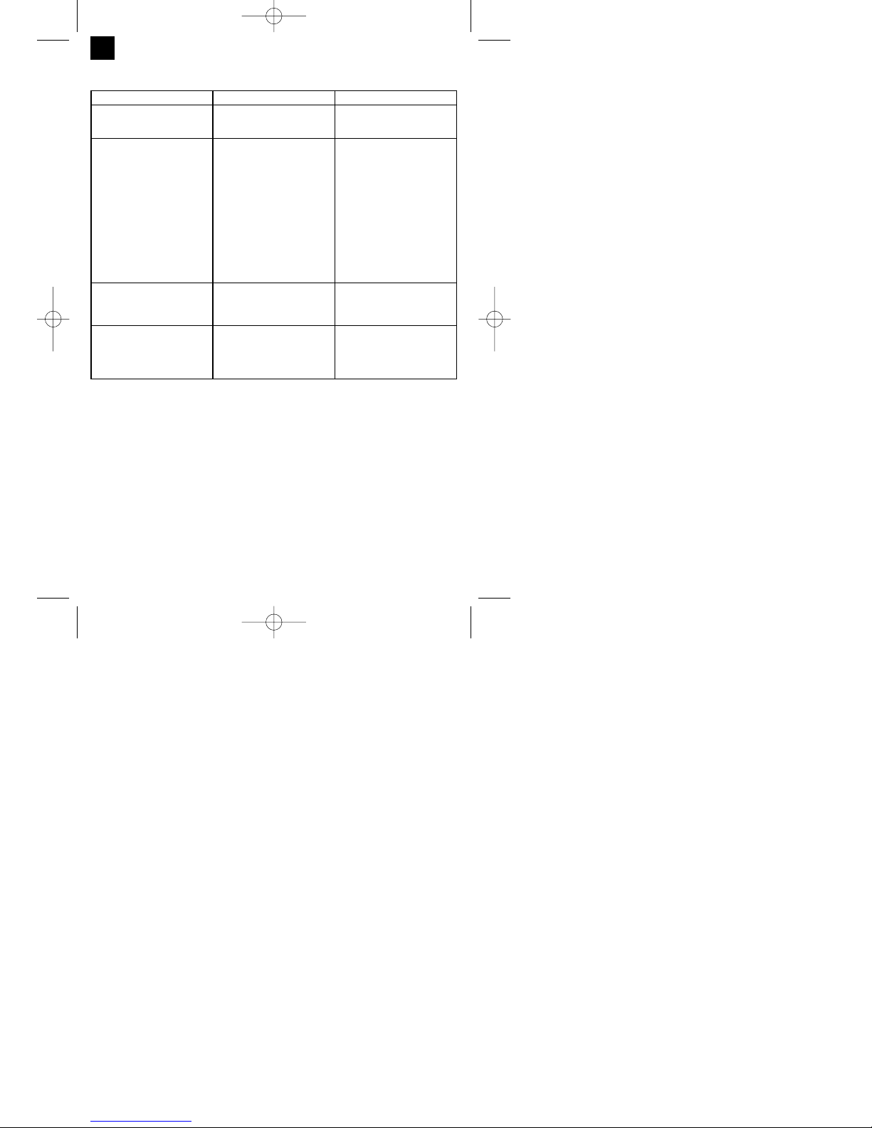
Fault Cause Remedy
Feed roller does not turn Power supply not connected
Wire feed controller set to 0
Check connection
Check setting
Feed roller turns, but does not feed
any wire
Incorrect roller pressure (see 5.4.3)
Roller brake set too firmly (see
5.4.3)
Dirty / damaged feed roller (see
5.4.3)
Damaged hose package
Contact tube wrong size / dirty /
worn (see 5.4.3)
Welding wire welded to the gas
nozzle / contact tube
Check setting
Check setting
Clean or replace
Check the wire guide jacket
Clean or replace
Release
After a lengthy period of use the
welding set does not work any
longer, the thermostat (3) control
light is lit
The welding set has overheated
due to being used for too long and
a failure to observe the reset time
Leave the set to cool down for at
least 20 – 30 minutes
Very poor weld Incorrect current / feed setting (see
6.1.1/6.1.2)
No / too little gas (see 6.1.3)
Check setting
Check setting and filling pressure
of the gas bottle
9. Troubleshooting
Anleitung_HSG_150_SPK7:_ 11.06.2008 15:18 Uhr Seite 24

25
GB
10. Key to symbols
EN 60974-1 European standard for
arc welding sets and
welding power supplies
with limited on time
Do not store or use the
appliance in wet or damp
conditions or in the rain.
Fuse with rated value in
A in the mains
connection
mains connection
U
1
Mains voltage 50 Hz Mains frequency
I1max Rated maximum mains
current
Symbol for falling
characteristic curve
Read the operating
instructions carefully
before using the welding
set and follow them
Metal inert and active
gas welding including
the use of filler wire
U
0
Rated idling voltage IP 21 Protection type
I
2
Welding current H Insulation class
Ø mm Welding wire diameter X On-load factor
transformer
The set is interference-suppressed in compliance with EC Directive 89/336/EEC
Anleitung_HSG_150_SPK7:_ 11.06.2008 15:18 Uhr Seite 25

Table des matières : Page
1. Consignes de sécurité 27
2. Description de lʼappareil et étendue de la livraison 27
3. Utilisation conforme à lʼaffectation 27
4. Caractéristiques techniques 28
5. Avant la mise en service 28-30
6. Commande 30-31
7. Nettoyage, maintenance et commande de pièces de rechange 31
8. Mise au rebut et recyclage 31
9. Dépannage 32
10. Explication des symboles 33
26
F
Anleitung_HSG_150_SPK7:_ 11.06.2008 15:18 Uhr Seite 26

Attention !
Lors de lʼutilisation dʼappareils, il faut respecter
certaines mesures de sécurité afin dʼéviter des
blessures et dommages. Veuillez donc lire
attentivement ce mode dʼemploi. Conservez-le bien
de façon à pouvoir disposer à tout moment de ces
informations. Si lʼappareil doit être remis à dʼautres
personnes, remettez-leur aussi ce mode dʼemploi.
Nous déclinons toute responsabilité pour les
accidents et dommages dus au non-respect de ce
mode dʼemploi et des consignes de sécurité.
1. Consignes de sécurité
Vous trouverez les consignes de sécurité
correspondantes dans le petit manuel ci-joint.
2. Description de lʼappareil et volume
de livraison (figure 1-8)
1. Poignée
2. Indicateur dʼétat
3 Témoin du contrôleur thermique
4. Recouvrement du boîtier
5. Emplacement pour les bouteilles de gaz
6. Galets de roulement
7. Interrupteur de mise en /hors circuit du courant
de soudage
8. Pied
9. Fiche de contact
10. Borne de mise à la terre (masse)
11. Faisceau de câbles
12. Buse de gaz
13. Chalumeau
14. Variateur de vitesse du fil de soudage
15. Sangle
16. Raccordement de lʼalimentation en gaz
17. Ecran de soudage
18. Tuyau de gaz inerte
19. Réducteur de pression
20. Manomètre
21. Vissage
22. Soupape de sécurité
23. Raccord du tuyau de gaz inerte
24. Bouton rotatif
25. Interrupteur du brûleur
26. 2 tubes de contact
2.1 Matériel de montage
a. 8 vis pour galets de roulement
b. 8 circlips pour galets de roulement
c. 8 rondelles pour galets de roulement
d. 4 vis pour poignée
e. 4 circlips pour poignée
f. 4 rondelles pour poignée
g. 2 vis pour pied
h. 2 circlips pour pied
p. 2 rondelles pour pied
j. 2 pinces pour flexible
k. 1 cadre de verre de protection
l. 1 verre de soudage
m. 1 verre de protection transparent
n. 2 douilles de maintien du verre de protection
o. 3 écrous pour poignée de retenue
p. 3 vis pour poignée de retenue
q. 2 chevilles dʼarrêt du verre de protection
r. 1 poignée
s. 1 cadre dʼécran de soudage
3. Utilisation conforme à lʼaffectation
Lʼappareil de soudage au gaz inerte est
exclusivement destiné au soudage de lʼaluminium en
processus MIG (métal-gaz inerte) et dʼaciers en
processus MAG (soudage à lʼarc avec électrode en
atmosphère active /métal-gaz actif) en utilisant les
électrodes à fil plein et les gaz correspondants.
La machine doit exclusivement être employée
conformément à son affectation. Chaque utilisation
allant au-delà de cette affectation est considérée
comme non conforme. Pour les dommages en
résultant ou les blessures de tout genre, le
producteur décline toute responsabilité et
lʼopérateur/lʼexploitant est responsable.
Veillez au fait que nos appareils, conformément à
leur affectation, nʼont pas été construits, pour être
utilisés dans un environnement professionnel,
industriel ou artisanal. Nous déclinons toute
responsabilité si lʼappareil est utilisé
professionnellement, artisanalement ou dans des
sociétés industrielles, tout comme pour toute activité
équivalente.
27
F
Anleitung_HSG_150_SPK7:_ 11.06.2008 15:18 Uhr Seite 27
4. Caractéristiques techniques
Branchement secteur : 230 V ~ 50 Hz
Courant de soudage : 25-120 A (max. 150 A)
Durée de mise en circuit X%:
10 20 30 60 100
Courant de soudage I
2
(A) :
120 90 75 52 40 25
Tension de marche à vide nominale U0: 48 V
Bobine de fil plein maxi. : 5 kg
Diamètre du fil plein : 0,6/0,8 mm
Fusible : 16 A
Poids : 25 kg
5. Avant la mise en service
5.1 Montage (fig. 5-21)
5.1.1 Montage des galets de roulement (6)
Montez les galets de roulement (6) comme indiqué
dans les figures 7, 9, 10, 11.
5.1.2 Montage du pied dʼappui (8)
Montez le pied dʼappui (8) comme indiqué dans les
figures 7, 9, 12, 13.
5.1.3 Montage de la poignée (1)
Montez la poignée (1) comme indiqué dans les
figures7, 14.
5.1.4 Montage de lʼécran de soudage (17)
Placez le verre de soudage (l) et par dessus, le
verre de protection transparent (m) dans le cadre
pour le verre de protection (k) (fig. 15).
Enfoncez les goupilles de fixation du verre de
protection (q) extérieur dans les perçages du
cadre de lʼécran de soudage (s). (fig. 16)
Mettez le cadre du verre de protection (k) avec le
verre de soudage (l) et le verre de protection
transparent (m) de lʼintérieur dans lʼencoche
dans le cadre de lʼécran de soudage (s),
appuyez les douilles de maintien du verre de
protection (n) sur les broches de maintien du
verre de protection (q), jusquʼà ce quʼelles
sʼengagent afin de sécuriser le cadre du verre de
protection (k). Le verre de protection transparent
(m) doit se trouver sur le côté extérieur. (fig. 17)
Plier le bord supérieur du cadre de lʼécran de
soudage (s) vers lʼintérieur (fig. 18/1.) et fléchir
les coins du bord supérieur (fig. 18/2.). Plier à
présent les côtés extérieurs du cadre de lʼécran
de soudage (s) vers lʼintérieur (fig. 18/3.) et
joindre,en appuyant avec force sur les coins des
bords supérieurs et les côtés extérieurs. Il faut
entendre nettement deux bruits dʼencliquetage
lorsque les broches de support sʼencrantent pour
chaque côté (fig. 18/4.)
Si les deux angles supérieurs de lʼécran de
soudage sont reliés, comme indiqué en figure
19, enfoncez les vis de la poignée de retenue (p)
de lʼextérieur dans les 3 trous de lʼécran de
soudage. (fig. 20)
Retournez lʼécran de soudage et mettez la
poignée (r) via le filetage des 3 vis de poignée de
retenue (p). Vissez à fond la poignée (r) avec les
3 écrous de la poignée de retenue (o) sur lʼécran
de soudage. (fig. 21)
5.2 Raccord de gaz (fig. 4, 5, 22-27)
5.2.1 Type de gaz
Lorsque lʼon soude avec un fil ininterrompu, une
protection antigaz est nécessaire, la composition du
gaz inerte dépend du procédé de soudage
sélectionné :
5.2.2 Montez la bouteille de gaz sur lʼappareil
(fig. 22-23)
La bouteille de gaz nʼest pas comprise dans la
livraison !
Montez la bouteille de gaz comme indiqué dans les
figures 22 à 23. Veiller à ce que la sangle (15) tienne
correctement et à ce que lʼappareil à souder ne
puisse pas basculer.
Attention ! Il est uniquement autorisé de monter des
bouteilles de gaz de 10 l au maximum sur les
emplacements réservés aux bouteilles de gaz (fig.
23/5). Si vous utilisez des bouteilles de gaz, elles
risquent de basculer, raison pour laquelle elles
doivent être placées uniquement à côté de lʼappareil.
Dans un tel cas, il faut alors bloquer la bouteille de
gaz pour lʼempêcher de basculer.
5.2.3 Raccord de la bouteille de gaz (fig. 7, 24-27)
Après avoir enlevé le capuchon de protection (fig.
24/A), ouvrez brièvement la valve de la bouteille
dans le sens écarté du corps (fig. 24/B).
Nettoyez le cas échéant les salissures du filet de
raccordement (fig. 24/C) avec un chiffon sec, sans
produit de nettoyage. Contrôlez si le joint sur le
28
F
Gaz inerte CO2 Argon/CO2 Argon Argon/O
Métal à souder
Acier non allié X X
Aluminium X
Acier inoxydable X X
Anleitung_HSG_150_SPK7:_ 11.06.2008 15:18 Uhr Seite 28

réducteur de pression (19) est présent et sʼil est dans
un état impeccable. Vissez le réducteur de pression
(19) dans le sens des aiguilles dʼune montre sur le
filet de raccordement (fig. 25/C) de la bouteille de
gaz (fig. 25). Faites passer les deux colliers de
serrage (j) au-dessus du tuyau de gaz inerte (18).
Enfichez le tuyau de gaz inerte (18) sur le raccord du
tuyau de gaz inerte (23) sur le réducteur de pression
(19) et le raccordement de lʼalimentation en gaz (16)
sur lʼappareil à souder et bloquez-le au niveau des
deux points de raccordement à lʼaide des colliers de
serrage (j). (fig. 26-27)
Attention ! Veillez à ce que tous les raccords (de gaz
ou autres) soient bien étanches ! Contrôlez les
raccords et les points de raccordement à lʼaide dʼun
spray à fuites ou en utilisant de lʼeau savonneuse.
5.2.4 Explication du réducteur de pression
(fig. 4/19)
On peut régler le débit du gaz sur le bouton rotatif
(24). Le débit de gaz réglé peut-être lu sur le
manomètre (20) en litres par minute (l/min). Le gaz
sort du raccord du tuyau de gaz inerte (23) et est
refoulé ensuite via le tuyau de gaz inerte (fig. 3/18)
jusquʼà lʼappareil à souder. (voir 5.2.3)
Attention ! Pour régler le débit de gaz, procédez
toujours comme indiqué au point 6.1.3.
Le réducteur de pression se monte sur la bouteille de
gaz à lʼaide du raccord vissé (21) (voir 5.2.3).
Attention ! Seul le personnel dûment qualifié est
autorisé à travailler sur le réducteur de pression et à
le réparer. Envoyez le cas échéant le réducteur de
pression défectueux à lʼadresse du service aprèsvente.
5.3 Raccord réseau
Assurez-vous, avant de connecter la machine,
que les données se trouvant sur la plaque de
signalisation correspondent bien aux données du
réseau.
Il est uniquement autorisé de faire fonctionner
lʼappareil lorsquʼil est raccordé à des prises de
courants de sécurité mises à la terre dans les
règles de lʼart.
5.4 Montage de la bobine de fil
(fig. 1, 5, 6, 28 – 36)
La bobine de fil nʼest pas comprise dans la livraison !
5.4.1 Types de fil
En fonction des cas dʼapplication, on a besoin de
différents fils de soudage. On peut utiliser lʼappareil à
souder avec des fils dʼun diamètre allant de 0,6 à 0,8
mm. Le cylindre dʼavance et les tubes de contact
correspondants se trouvent dans lʼappareil. Le
cylindre dʼavance, le tube de contact et le diamètre
du fil doivent toujours être adaptés.
5.4.2 Capacité de la bobine de fil
On peut monter des bobines de fil de maximum cinq
kilos dans lʼappareil.
5.4.3 Montage de la bobine de fil
Ouvrir le recouvrement du boîtier (fig. 1/4)
Contrôlez que les enroulements sur la bobine ne
se superposent pas pour pouvoir garantir un
déroulement homogène du fil.
Description de lʼunité de guidage de fil
(fig. 28-30)
A Arrêt de bobine
B Support de la bobine
C Broche dʼentraînement
D Support des rouleaux presseurs
E Rouleau presseur
F Vis dʼajustage pour contre-pression
G Levier de serrage
H Tube de guidage
I Support des cylindres dʼavance
J Bobine de fil
K Orifice dʼentraînement de la bobine fil
L Cylindre dʼavance
M Logement du faisceau de tuyaux
N Vis dʼajustage pour frein du rouleau
Montage de la bobine de fil (fig. 28,29)
Montez la bobine de fil (J) sur le support de la bobine
(B). Veillez à ce que lʼextrémité du fil plein soit bien
déroulée sur le côté du guidage de fil métallique, voir
la flèche.
Veillez au fait que lʼarrêt de bobine (A) soit enfoncé
et que la broche dʼentraînement (C) se trouve bien
dans lʼorifice dʼentraînement de la bobine de fil (K).
Lʼarrêt de bobine (A) doit à nouveau sʼencranter audessus de la bobine de fil (J). (fig. 29)
Introduction du fil plein et ajustage du guidage
de fil métallique (fig. 30-36)
Desserrez le levier de serrage (G), relever le
support des rouleaux presseurs (D). (fig. 30)
Retirez le tube de guidage (H) le cas échéant.
(voir le repère en fig. 31)
Défaire le support des cylindres dʼavance (I) du
dispositif dʼarrêt en le tournant vers la gauche et
sortez-le vers le haut. (fig. 32)
29
F
Anleitung_HSG_150_SPK7:_ 11.06.2008 15:18 Uhr Seite 29

Contrôlez le cylindre dʼavance (L). Lʼépaisseur
du fil correspondante doit être indiquée sur la
face supérieure du cylindre dʼavance (L). Le
cylindre dʼavance (L) est doté de 2 rainures de
guidage. Retournez le cylindre dʼavance (L) le
cas échéant, ou remplacez-le. (fig. 33)
Remettez le support des cylindres dʼavance (I)
en place et bloquez-le dʼune rotation à droite.
Entrez le tube de guidage (H) à nouveau jusquʼà
ce quʼil se termine à environ 5 mm du cylindre de
pression et dʼavance (E/L).
Retirez la buse de gaz (fig. 5/12) en tournant le
brûleur vers la droite (fig. 5/13), dévissez le tube
de contact (fig. 6/26) (fig. 5 - 6). Posez le
faisceau de tuyaux (fig. 1/11) le plus droit
possible sur le sol en partant de lʼappareil à
souder.
Couper les premiers 10 cm du fil plein de
manière à obtenir une coupe droite, sans saillie,
distorsion ni salissure. Enlever les bavures de
lʼextrémité du fil plein.
Poussez lʼélectrode à fil plein dans le tube de
guidage (H), entre le cylindre de pression et celui
dʼavance (E/L) dans le logement du faisceau de
tuyaux (M). (Fig. 34) Introduisez
précautionneusement le fil plein à la main dans
le faisceau de tuyaux jusquʻà ce quʼil dépasse
dʼenv. 1 cm du brûleur (fig. 5/13).
Desserrez la vis dʼajustage de la contre-pression
(F) de quelques tours. (fig. 36)
Rabattez le support des rouleaux presseurs (D)
vers le bas et arrêtez-le avec le levier de serrage
(G). Sʼil est impossible ou difficile dʼarrêter le
levier de serrage (G), il faut desserrer encore la
vis dʼajustage de la contre-pression (F). (fig. 35)
Réglez à présent la vis dʼajustage de la contre-
pression (F) de manière que lʼélectrode à fil plein
se trouve entre le rouleau presseur (E) et le
cylindre dʼavance (L) sans être écrasé. (fig. 36)
Vissez le tube de contact qui convient (fig. 6/26)
au diamètre du fil plein utilisé sur le brûleur (fig.
5/13) et enfichez la buse de gaz en tournant vers
la droite (fig. 5/12).
Réglez la vis dʼajustage du frein du rouleau (N)
de manière que le fil puisse encore être guidé et
que la bobine sʼarrête automatiquement après le
freinage du guidage de fil.
6. Commande
6.1 Réglage
Comme le réglage de lʼappareil de soudage se fait
de façon différente en fonction du cas dʼapplication,
entreprenez les réglages sur la base dʼun soudage
test.
6.1.1 Réglage du courant de soudage
Le courant de soudage peut être réglé en 6 étapes
sur lʼinterrupteur de mise en /hors circuit du courant
de soudage (fig. 1/7). Le courant de soudage requis
dépend de lʼépaisseur du matériau, de la profondeur
de marquage désirée et du diamètre du fil plein
utilisé.
6.1.2 Réglage de la vitesse de lʼavance de fil
La vitesse de lʼavance de fil est automatiquement
adaptée au réglage du courant utilisé. Un réglage de
précision de la vitesse de lʼavance de fil peut se faire
en continu sur le variateur de vitesse du fil de
soudage (fig. 1/14). Il est recommandé de
commencer le réglage à lʼétape 5 qui représente une
moyenne et de régler une nouvelle fois
ultérieurement, le cas échéant. La quantité de fil
requise dépend de lʼépaisseur du matériau, de la
profondeur de marquage, du diamètre du fil plein
utilisé et même de la grandeur des distances à
ponter des pièces à souder.
6.1.3 Réglage du débit de gaz
Le débit de gaz peut être réglé en continu sur le
réducteur de pression (fig. 4/19). Il est indiqué sur le
manomètre (fig. 4/20) en litres par minute (l/min).
Débit de gaz recommandé dans les pièces sans
courant dʼair : 5 – 15 l/min.
Pour réguler le débit du gaz, desserrez tout dʼabord
le levier de serrage (fig. 28/G) de lʼunité dʼavance de
fil afin dʼéviter une usure inutile du fil (voir 5.4.3).
Etablissez le branchement secteur (voir point 5.3),
mettez lʼinterrupteur de mise en /hors circuit du
courant de soudage (fig.1/7) sur le niveau 1 et
actionnez lʼinterrupteur du brûleur (fig. 5/25) pour
libérer le flux de gaz. Réglez à présent le flux de gaz
désiré sur le réducteur de pression (fig. 4/19).
Rotation à gauche du bouton rotatif (fig. 4/24) :
Débit moindre
Rotation à droite du bouton rotatif (fig. 4/24) :
Débit de gaz plus important
Serrez à fond le levier de serrage (fig. 28/G) de
lʼunité dʼavance de fil.
6.2 Raccordement électrique
6.2.1 Raccord réseau
Cf. point 5.3
30
F
Anleitung_HSG_150_SPK7:_ 11.06.2008 15:18 Uhr Seite 30
 Loading...