

Page 1
INSTRUCTIONS
Part# 1002437
6/28/05
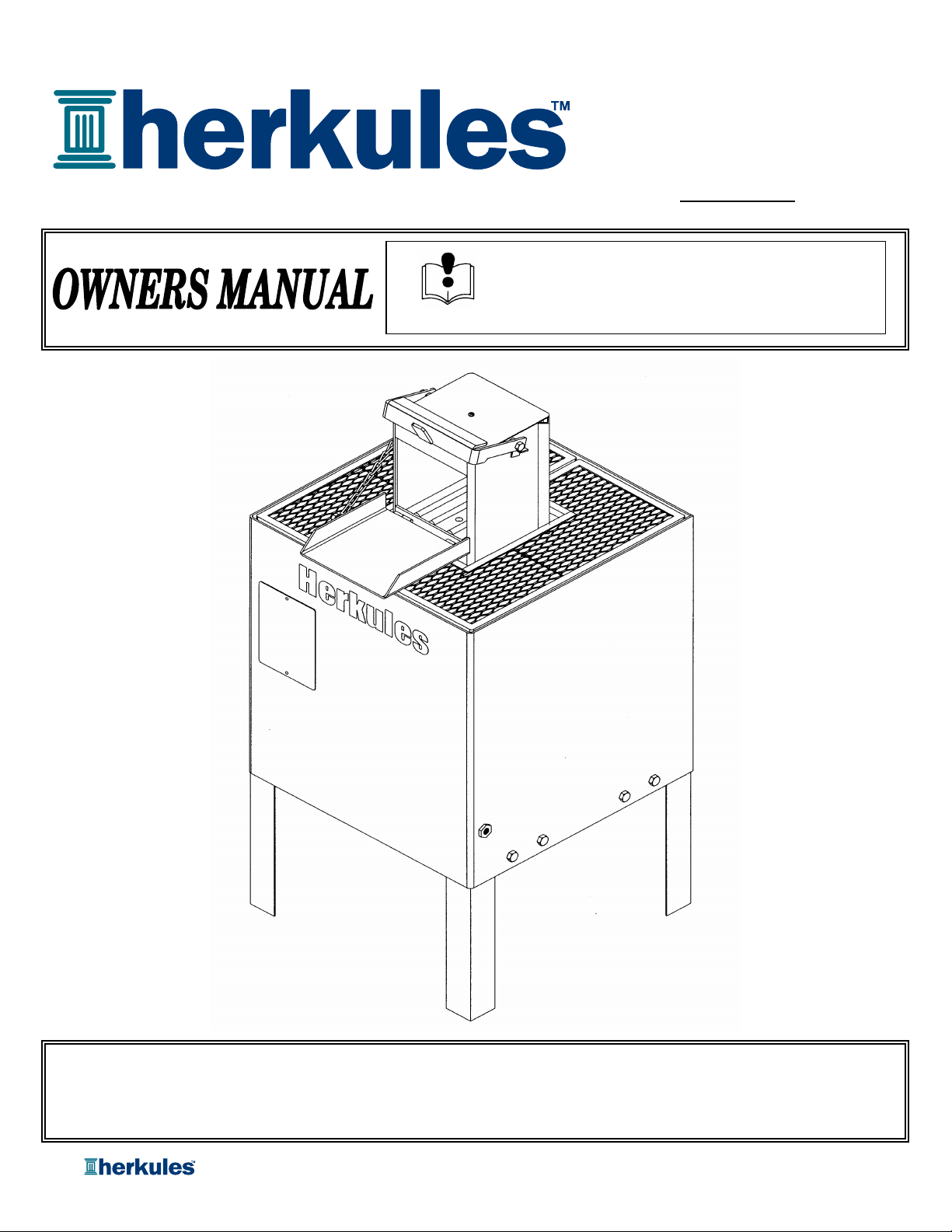
Model: OFC3
This manual contains important information concerning the
installation and operation of the crusher listed above.
Read manual thoroughly and keep for future reference
Herkules Equipment Corporation 2760 Ridgeway Court Walled Lake, MI 48390-1662 USA
248-960-7100 800-444-4351 Fax 248 960-7109
website: www.herkules.us e-mail: [email protected]
Page 1 of 8
Page 2

Table of Contents
Warnings …………………………………………………………………………………………………………………. 3
Model Information (List of models with descriptions and data) ……………………………………………… 4
Installation
Inspection
Operation ………………………………………………………………………………………………………………… 6
Maintenance …………………………………………………………………………………………………………. 7
Repair …………………………………………………………………………………………………………………….. 7
Drawings with part lists: ……………………………………………………………………………………………. 7-8
……………………………………………………………………………………………………………….. 5
………………………………………………………………………………………………………………… 6
Warning Symbol Caution Symbol
WARNING
This symbol alerts you to the possibility of
serious injury or death if you do not follow
the instructions.
Serial Number
Model Number
Purchase Date
Distributor
CAUTION
This symbol alerts you to the possibility of
damage to or destruction of equipment if you
do not follow the instructions.
Page 2 of 8
Page 3

WARNING
FAILURE TO HEED THE FOLLOWING WARNINGS MAY RESULT
IN PERSONAL INJURY AND/OR PROPERTY DAMAGE.
1 Herkules will not be held responsible for any personal injury and/or property damaged caused
due to owner/operator failure to follow the warnings and cautions listed in this manual.
2 Read and understand all warnings, cautions and instructions before operating this equipment.
3 It is the owner/operators responsibility to maintain the legibility of all warning and instruction labels.
4 Do not alter or modify any part of this equipment.
5 Do not attempt to bypass the door/latch interlock system. The door interlock is provided for operator safety.
6 DO NOT open the door while the unit is operating. Always wait for the crusher to cycle completely.
7 Crush only intended matter for the crusher.
8 Always wear safety glasses when operating the crusher.
9 Always wear suitable industrial gloves when handling crushed objects to prevent injury.
10 Check equipment regularly for proper operation and repair or replace worn or damaged parts immediately.
11 Any crusher that appears to be damaged in any way, is badly worn or operates abnormally shall be removed
from use until repairs are made. Use only manufacture's approved accessories and service parts.
Contact a factory authorized service center for repairs.
12
DO NOT REMOVE THIS LABEL. REPLACE IF DAMAGED.
Page 3 of 8
Page 4
Model Information
SPECIFICATIONS
Maximum crushing pressure 30,000 Ibs.
Filter capacity Four filters
Filter type Car/light truck
Filter crush Up to 80%
Residual oil removed from crushed filter 95 - 98%
Time to crush filter 55 seconds
Overall width 27-1/2"
Overall height 55"
Overall depth 27-1/2"
Chamber width 9"
Chamber height 8-7/8"
Chamber depth 9"
Required air pressure 100-120 p.s.i.
Total weight 550 Ibs.
DESCRIPTION
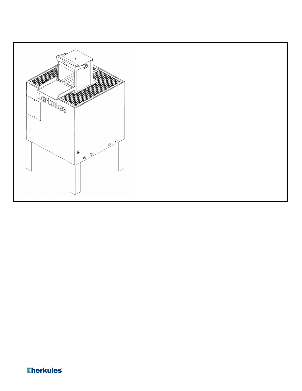
Model OFC3 is a production crusher capable of crushing four filters at one time. The crusher is designed for
automotive and light truck shops to crush and dispose of used oil filters in an environmentally correct manner. The
crusher provides the following features:
• Powerful 15 ton air bag crushing plate technology assures the force necessary to do the job when
crushing four filters.
• Operates with external air only. No electric power is required.
• Safe double lock door protects operator.
• Removes 95-98% of residual oil from oil filter.
• Easy connection for oil drain off.
• Four oil filter capacity.
Page 4 of 8
Page 5
OWNER/OPERATOR RESPONSIBILITY
r
It is the responsibility of the owner/operator to properly use and maintain this equipment.
The instructions and warnings contained in this manual shall be read and understood by the owner/operator prior
to operating this equipment.
If an owner/operator does not understand English, the contents of this manual shall be explained in the owner/
operator native language to assure the owner/operator comprehends.
It is the responsibility of the owner/operator to maintain the legibility of all warning and Instruction labels.
The owner/operator shall retain this manual for future reference to Important warnings, operating and maintenance
instructions.
INSTALLATION
Installation consists of anchoring the unit
to the floor, connecting an external air
supply with 100 to 120 p.s.i. and routing
the waste oil drain to a suitable waste oil
reservoir.
DO NOT attempt to operate the unit while
on a skid. The initial crush of the oil
filter(s) will cause the unit to move or jump
if not secured properly. The unit is
equipped with a 125 p.s.i. relief valve that
will bleed off air if the unit is inadvertently
connected to an air source greater than
125 p.s.i.
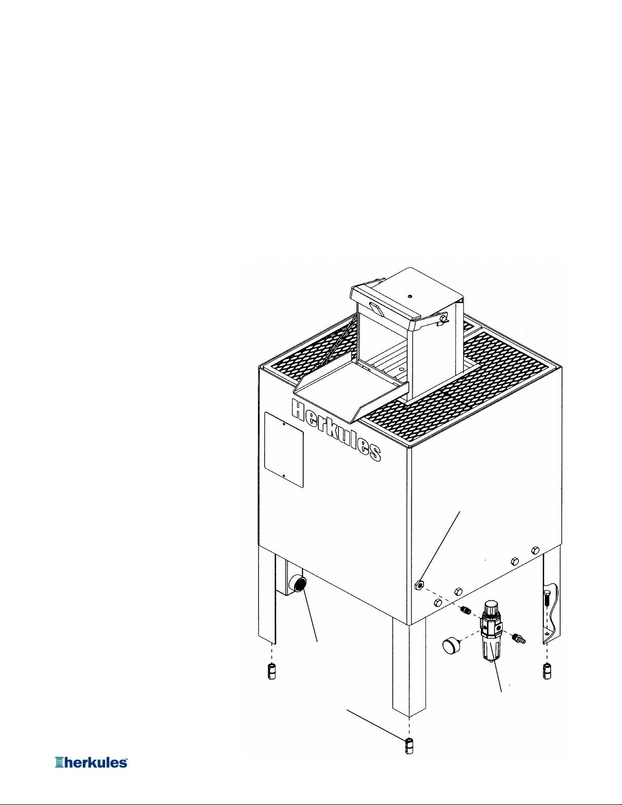
See Figure (1). Install the crusher as follows.
A. Anchor the unit to the floor using
1/2" diameter hardware.
B. Connect the supplied pressure
regulator/filter to the crusher 3/8"
NPT air inlet fitting.
Figure 1
3/8 NPT Air Inlet
C. Connect the external air supply to
the pressure regulator/filter.
D. Connect the waste oil drain line to
the crusher 1-1/2' NPT waste oil
drain fitting.
Waste oil
drain fitting
Filter/Regulator
1/2" Floor Ancho
Page 5 of 8
Page 6

INSPECTION
e
Prior to operation a visual Inspection shall be made. Check crusher for leaks, worn or missing parts.
Any crusher that appears to be damaged in any way, is badly worn or operates abnormally shall be removed
from use until repairs are made. Contact a factory authorized service center for repairs.
If over pressurizing of the equipment is believed to have occurred, contact a factory authorized service center for
inspection of the crusher.
An annual inspection by a factory authorized service center is recommended.
OPERATION
Turn the external air supply on.
Verify the pressure gauge on the pressure regulator/filter reads between 100 and 120 p.s.i. Adjust the regulator
as required.
NOTE:
If the external air supply is less than 100 p.s.i., the crusher will operate but the crushing performance is reduced.
Lift the door latch and pull the door down to gain access to the crushing chamber.
Place the oil filter(s) to be crushed gasket side down on the bottom of the crushing chamber. Arrange the filters as
follows:
Quantity & Typ
(1) Auto filter Center of ram plate
(2) Auto filters Opposite corners
(3) Auto filters (2) in back corners and (1) in front center
(4) Auto filters (2) in back corners and (2) in front corners
Close the door and pull the door latch down securely. The crusher will operate for approximately 55 seconds with an
audible air sound.
Wait until the air flow stops.
Position
WARNING
The crushing mandrel may be still moving when the
door is opened. Wait until the mandrel stops before
placing hand in chamber.
Lift door latch and open door.
WARNING
A crushed oil filter may have jagged metal edges. Use
good industrial work gloves to protect the hands
when removing a crushed oil filter.
Remove the crushed oil filter and dispose of it in an environmentally correct manner.
Page 6 of 8
Page 7
SAFETY INFORMATION
R
t
Read and understand all warnings, cautions and instructions before operating this equipment. Caution should be used
when operating this equipment as personal injury and/or property damage can result from equipment misuse. Adequate
personal protection is recommended to prevent splashing of oil on the skin or in the eyes.
MAINTENANCE
Regularly check the pressure filter/regulator moisture trap for water. Drain as required.
Regularly check the waste oil drain line system to prevent oil backing up in the crusher chamber. and causing an oil spill.
Clean, repair, adjust as required.
Regularly clean the crusher chamber to remove any accumulated oil sludge, metal particles or any other debris that
could affect the crusher operation or block the waste oil drain system.
Apply grease to door hinges on a regular basis to prevent the door from binding.
Apply motor oil to door latch pivot points on a regular basis to prevent latch from binding.
REPAI
No service parts are available for this oil filter crusher. Special tools and procedures are required for repair. If
repair is required, contact Herkules Equipment Corporation Customer Service, (800-444-4351) for your nearest authorized
service center.
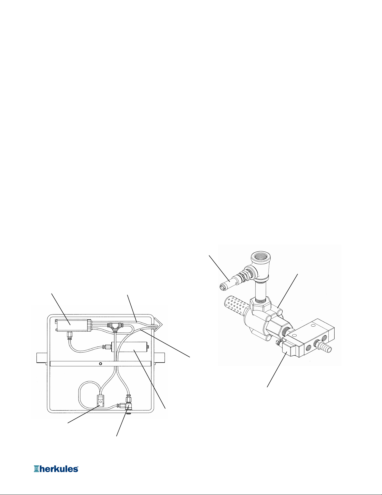
SERVICE PARTS
Pneumatic Timer
#008-369
Limit Valve
#M1B
Safety Valve
#700-114
Valve Exhaus
#008-368
Tubing 5/32 black
#M5-BLACK
Tubing 5/32 blue
#M5
Valve 4-Way
#009-141
Volume Chamber
#008-379
Limit Valve
#M2
Page 7 of 8
Page 8
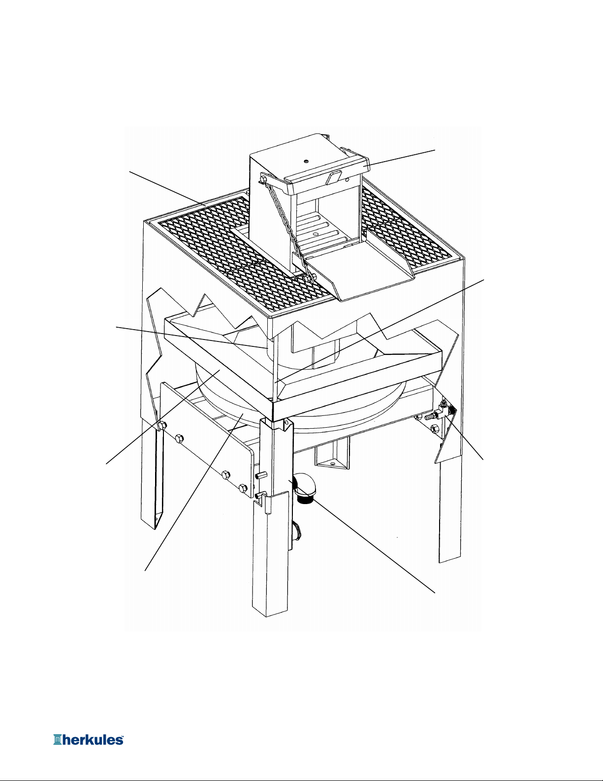
SERVICE PARTS
Grating Assembly
#11843
Piston Assembly
#11846
Handle Assembly
#11844
Clean Out Rod
#10028
Drain Pan
#11857
Tee Assembly
#C12EB
Air Bag
#11859
Reservoir Assembly
#10031
Page 8 of 8
 Loading...