

Part# 1000556C
07-09-02 TN
Revision: C
Manufacturing Systems and Equipment for the Automotive and Industrial Markets
CRUSHING
Equipment Corporation
HANDLING
LIFTING CURING VACUUMING
WASHING
Herkules Equipment Corporation
248-960-7100 1-800-444-4351 Fax 248-960-7109
TM
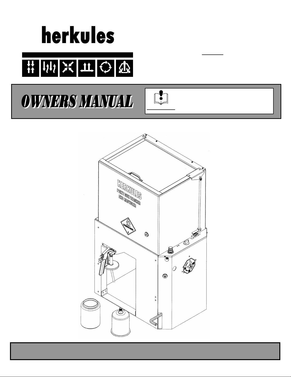
GW/R-SS GW/R-SS-R
GW/R-3-SS GW/R-3-SS-R
This manual contains important information
concerning the installation and operation of the gun
washers listed at the right. Read manual thoroughly
INSTRUCTIONS and keep for future reference.
Models:
01001245(200)
2760 Ridgeway Court Walled Lake, MI 48390-1662 USA
Table of Contents
Warnings ……………………………………………………………………………………….. 3-4
Model Information …………………………………………………………………………….. 5
Installation ....................................................................................................................... 6
Operation ....................................................................................................................... 6-9
Preventive Maintenance ................................................................................................ 10
Troubleshooting .............................................................................................................. 11
Notes ........................................................................................................................... 12-13
Parts layout for GW/R-SS ……………………………………………………………………… 14-15
Parts layout for GW/R-3-SS ………………………………………………………………….. 16-17
Additional Parts for GW/R-SS-R, GW/R-3-SS-R ………………………………………….. 18
Warning Symbol Caution Symbol
This symbol alerts you to the possibility of
serious injury or death if you do not follow
the instructions.
WARNING
This symbol alerts you to the possibility of
damage to or destruction of equipment if
you do not follow the instructions.
Serial Number _____________ Purchase Date
Distributor _______________ Model Number
CAUTION
2 3
WARNING
INSTRUCTIONS
EQUIPMENT MISUSE HAZARD
Equipment misuse can cause the equipment to rupture, malfunction, or start unexpectedly
and result in serious injury.
•
This equipment is for professional use only.
•
Read all instruction manuals, tags, and labels before operating the equipment.
•
Use the equipment only for its intended use.
•
Do not alter or modify this equipment.
•
Do not exceed the maximum working pressure of the lowest rated system component.
•
Do not operate the gun washer at a pressure above the maximum working pressure rating of the
gun(s) being cleaned.
•
Route the hoses away from traffic areas, sharp edges, moving parts, and hot surfaces.
• Do not use the hoses to pull the equipment.
• Do not move pressurized equipment.
• Use fluids or solvents that are compatible with the equipment wetted parts. Read the fluid and
solvent manufactures warnings.
• Comply with all applicable local, state and national fire, electrical and other safety regulation.
PRESSURIZED EQUIPMENT HAZARD
Spray from hose leaks, ruptured components, or from operating the gun washer with an open
lid can splash fluid in the eyes or on the skin and cause serious injury.
• A safety device has been installed to shut off the pump when the gun washer lid is opened. Do not tamper with
or alter this device.
• Open the gun washer lid slowly.
• Do not prop the gun washer lid open with an object or by any other means.
• Do not stop or deflect fluid leaks with your hand, body, glove, or rag.
• Tighten all fluid connections before operating the equipment.
• Replace worn, damaged, or loose parts immediately.
WARNING
FIRE AND EXPLOSION HAZARD
Improper grounding, poor air ventilation, open flames, or sparks can cause a hazardous
condition and result in fire or explosion and serious injury.
•
Ground the equipment. See Installation for grounding procedure.
Provide fresh air ventilation to avoid the build up of flammable fumes from the solvent.
•
•
Extinguish all open flames or pilot lights in gun washer area.
• Electrically disconnect all equipment in the gun washer area.
• Keep the gun washer area free of debris, including solvent, rags, and gasoline.
• Do not turn on any light switch in the gun washer area while operating or if fumes are present.
• Do not smoke in the gun washer area.
Do not operate a gasoline engine in the gun washer area.
•
•
Follow the gun manufactures solvent and other cleaning recommendations.
• Use solvent with the highest possible flash point.
• If there is any static sparking while using the equipment, stop operation immediately. Identify and correct
the problem.
• Drain the solvent into a proper storage container when gun washer(s) is not in use.
TOXIC FLUID HAZARD
Hazardous fluids or toxic fumes can cause serious injury or death if splashed in eyes or on
the skin, swallowed, or inhaled.
•
Know the specific hazards of the fluid you are using. Read the fluid manufactures warnings.
•
Store hazardous fluid in an approved container. Dispose of hazardous fluid according to all local, state and
national guidelines.
•
Wear the appropriate protective clothing, gloves, eyewear and respirator.
• Pipe and dispose of the exhaust air safely. If diaphragm fails, the fluid may be exhausted along with the air.
4
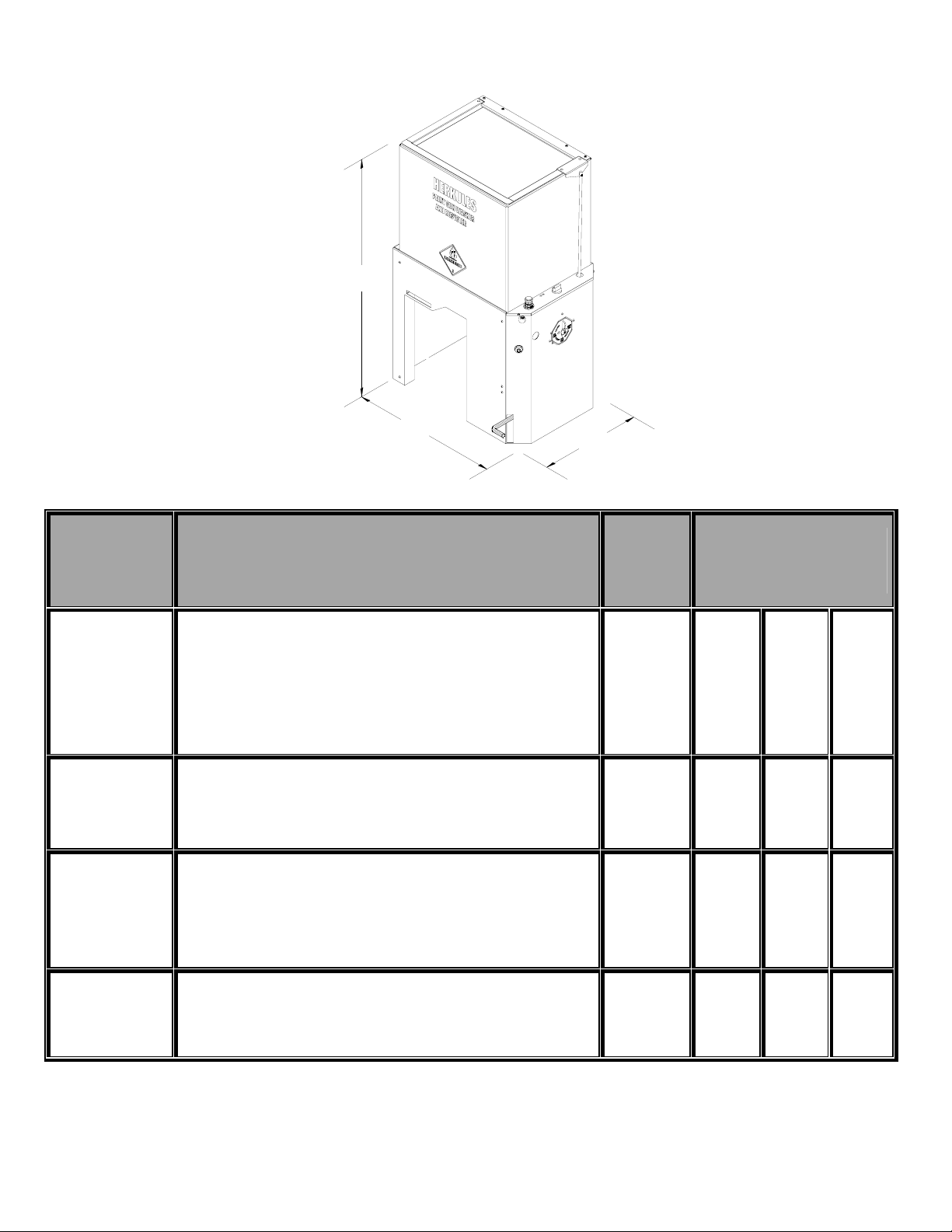
Model Information
A
B
Model Description
01001245(203)
C
Weight
lb. (kg.)
Dimension in. (mm.)
A
B
*C
GW/R-SS
GW/R-SS-R
GW/R-3-SS
GW/R-3-SS-R
Two gun, two cup paint gun washer/recycler equipped with high
volume diaphragm pump, foot operated lid opener, filter-regulator,
timer, stainless steel tank, and stainless steel lid for use with water
based cleaning solutions or standard lacquer thinner solvents.
GW/R-SS equipped with two diaphragm pumps, one for washing
and one for rinsing.
GW/R-SS adapted for cleaning pressure pot systems, paint
hoses, and cans up to five gallons plus a hand held brush for
manual cleaning of parts
GW/R-3-SS equipped with two diaphragm pumps, one for washing
and one for rinsing
(38.6)
(39.5)
85
86
(39)
86
(39)
87
42
(1067)
42
(1067)
42
(1067)
42
(1067)
25.5
(648)
**25.5
(648)
25.5
(648)
**25.5
(648)
18
(457)
18
(457)
18
(457)
18
(457)
Note: Models GW/R-SS-X, GW/R-SS-R-X, GW/R-3-SS-X, and GW/R-3-SS-R-X include a factory installed Fume Extractor
* Foot Pedal Protrudes 4.5” (114 mm.) past the front of the Gun Washer.
** Must allow room for 5-gallon can of solvent for the clean rinse option on the left side of the Gun Washer.
5
Installation
Installing the Gun Washer
Place gun washer on a level surface in a properly
ventilated paint mixing room.
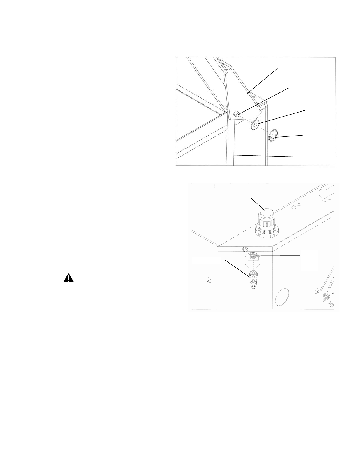
Connection the Foot Operated Lid Opener
1. Align the hole in the Lid Rod with the hole in the Lid Bracket
and insert the Clevis Pin through the holes (see fig. 1).
2. Place the 1/4” Flat Washer over the Clevis Pin
3. Attach the Circle Cotter Pin to the Clevis Pin (see Fig. 1).
Grounding the Gun Washer
1. Connect the ground wire on the gun washer’s pump
to a true earth ground.
2. Ground all equipment used or located in the gun
washer area.
Connecting the Air Line
1. Install a 1/4 in. npt male coupler, that is compatible
with the quick disconnect of your air supply line, into
the air inlet elbow (see Fig. 1).
2. Connect air line with 90-120 psi to the coupler.
CAUTION
Do not change the setting of the filter/regulator.
this could damage the filter/regulator or pump.
Figure 1
Figure 2
Q.D. Coupler
01001245(220)
Lid Bracket
Clevis Pin
Flat
Washer
Circle
Cotter Pin
Lid Rod
Filter/Regulator
Air Inlet
Elbow
6

Operation
Filling the Gun Washer with Fluid
1. Close ball valve located on the bottom of the tank. To clean guns not mentioned here, use the long or short stem
2. Pour five gallons (18.9 liters) of high quality, slow
evaporating solvent into the tank. DuPont 3661S or
equivalent is recommended.
Preparing the Equipment to be Washed
1. Remove paint cup or paint line and the air line from
the paint gun.
2. Drain excess paint from cup and gun.
3. Remove all gauges and regulators.
CAUTION
All pressure gauges must be removed before
placing the equipment in the gun washer to
avoid damaging the gauges.
4. Lock the gun trigger in the open position by placing
the trigger lock around the gun handle and trigger
(see Fig. 3).
Figure 3
Long Stem Support
Placing Equipment in the Gun Washer
supports as needed (see Fig. 3). For questions or adapter kits
contact your paint gun washer distributor.
Siphon Feed Guns
Place the gun siphon tube on the short stem support.
Gravity Feed Guns (HVLP)
Place the paint inlet of gun over the 45 deg. stem support so
that the gun rests in between the wire supports. Attach the air
cap assembly to the air inlet of the gun (see fig 3).
Pressure Feed Guns
Place the long stem support over the short stem support.
Place paint inlet of gun on long stem support (see fig.3).
Pots and Cups
Place pots and/or cups on divider platform over front spray
nozzles.
Trigger Lock
Air Cap Assembly
Paint Cup
Short Stem Support
Siphon Feed Gun
01001245(206)
45 Deg. Stem Support
7

Operation
Additional Hose and Can Washing Features
(Models GW/R-3-SS, GW/R-3-SS-R)
Internal Washing of Paint Lines
Remove the brass plugs from the hose wash bulkheads (see
Fig. 4). Install a female fluid quick coupler with 1/4 in. npt male
threads (suitable for lacquer thinner) into the hose wash
bulkheads. Connect the paint line to the couplers. Set the
pointer on the shield to hose clean and operate the gun
washer.
Hose Wash
Bulkhead
Hose Wash
Bulkhead
Figure 4
01001245(204)
Internal Washing of Paint Lines with Guns Attached
Remove the brass plug from the hose wash bulkhead on the
front of the shield. Install a female fluid quick coupler with 1/4
in. npt male threads (suitable for lacquer thinner). Connect
paint line with gun attached, to the coupler. Set the pointer on
the shield to the hose clean position and operate the gun
washer. To “bleed” the paint (into a container) hold the trigger
of the gun open until thinner begins to flow.
Internal and External Washing of Paint Lines with Guns
Attached
Install a female fluid quick coupler with 1/4 in. npt male threads
(suitable for lacquer thinner) into the Q.D coupler in the center
of the manifold (see Fig. 5). Connect the paint line with gun
attached, to the coupler. Place the paint line with gun attached
inside the gun washer. Lock the gun trigger in the open
position with the wire trigger lock. Set the pointer on the shield
to the gun clean position. Operate the gun washer.
Washing Pressure Pot and Lid
Insert the spray nozzle assembly, hanging on the back of the
manifold, into the Q.D. coupler in the center of the manifold
(see Fig. 5). Place pot over spray nozzle. Place the pickup
tube of lid over one of the short stem supports (remove
gauges). Operate gun washer.
Washing Five Gallon Cans
Insert the spray nozzle assembly, hanging on the back of the
manifold, into the Q.D. coupler in the center of the manifold
(see Fig. 5). Place five-gallon can over spray nozzle. Operate
gun washer.
Figure 5
Spray nozzle
assembly
01991149(102)
8

Operation
Rinsing of Paint Equipment
Manual Cleaning of Paint Equipment
(Models GW/R-SS-R, GW/R-3-SS-R) (Models GW/R-3-SS, GW/R-3-SS-R)
Place a five-gallon can of clean solvent next to gun washer.
Remove the cap from the can and replace it with the plug
provided in the parts bag. Insert the siphon tube through the
plug, and connect it to the flare fitting on the side of the gun
washer (see Fig. 6). After the washing cycle is finished, press
and hold the rinse button for approximately 3-6 seconds.
Operating Fume Extractor
(Models GW/R-SS-X, GW/R-SS-R-X, GW/R-3-SS-X,
GW/R-3-SS-R-X)
Attach a 1-1/4” exhaust hose (not supplied) to the fume
extractor on the back of the gun washer (see fig. 6). Run the
other end of the hose to the exhaust of the shop paint booth.
DO NOT OPERATE THE GUN WASHER WITHOUT
CONNECTING THE EXHAUST HOSE. The fume extractor will
activate whenever the lid is opened.
Figure 6
Fume Extractor
Exhaust Hose
Rinse Button
Siphon Tube
Plug
01001245(205)
Set the pointer on the shield to the brush clean position. With
the pointer in the brush clean position, the brush will be
activated whenever the lid is opened.
Figure 7
Manual Clean
Brush
Operating the Gun Washer
1. Make sure all wire trigger locks and other accessories are
inside the gun washer tank.
2. If washing only one set of equipment, place empty cans
over the unused nozzles and/or stem supports to prevent
solvent spray from hitting the underside of the gun washer
lid.
3. Close the gun washer lid.
4. Set the pointer to Gun Clean.
5. Turn the timer knob clockwise 90 degrees to the ON
position to start the gun washer. The gun washer will run for
90 seconds. Turning the timer knob less than 90 degrees
will reduce the timing cycle. Paint equipment will clean in 60
to 90 seconds.
6. If the lid is opened prior to the end of the timing cycle, the
safety air cutoff switch will stop the gun washer. The gun
washer will start again when the lid is closed if time
remains on the timer.
Note: Open and close the lid slowly to minimize solvent
vapor escape.
7. Remove the equipment from the gun washer and wipe off
any remaining solvent. The gun hanger on the front of the
stand can be used to dry the guns.
9
Orifice
Plate
Brush
Filter
01001245(200)

Preventive Maintenance
1. Drain excess paint from cup or pot before placing in gun washer.
2. Drain paint sludge from gun washer tank weekly. Do this after a weekend so that it has settled. Open ball valve and drain until clear
solvent flows. Add solvent to 1” above intake filter.
4. Remove the filter bowl and check the filter inside the regulator for excess buildup approx. every 6 months
5. Change solvent completely when objects being cleaned become tacky to the touch.
6. Clean inside of tub and intake filter assembly #70 before filling with solvent.
CAUTION
Do not change the setting of the filter/regulator.
This could damage the filter/regulator or pump.
Figure 8
Filter/Regulator
#T17M
Filter
#1001382
Filter Bowl
10

Problem Possible Solution
Gun washer will not turn on.
shield assembly.
Gun washer turns on but
pumps slowly or not at all.
MAINTENANCE.
The solvent should be an inch above the intake filter (#70).
the pump bracket is closed in the downward position.
Troubleshooting
1. Make sure the air line is properly connected with 90-120 psi.
2. Make sure lid is fully closed. Make sure the limit valve
on the pump bracket is closed in the downward position.
3. Check all air connections to ensure that there are no leaks.
4. Make sure timer cam is engaging the limit valve (#M1C) on the
5. Make sure timer is on and functioning correctly.
1. Make sure intake filter (#70) is not clogged (Clean or replace).
2. Make sure the air line is properly connected with 90-120 psi.
3. Check all air connections to ensure that there are no leaks.
4. Drain filter/regulator of water. See number 3 of PREVENTIVE
5. Make sure there are 5 gallons of clean solvent in the gun washer.
6. Make sure lid is fully closed. Make sure the limit valve on
7. Make sure manifold nozzles and stem supports are not clogged.
Gun washer will not shut off. 1. Make sure timer cam (#M230-001A) is moving. If its not, slightly
loosen the nuts holding the limit valve (#M1C) on the shield.
Reposition valve and tighten nuts.
Rinse cycle will not work. 1. Check the level of the rinse solvent.
2. Check all fluid connections to ensure that there are no leaks.
Manual Brush will not work 1. Clean or replace the brush filter (see fig. 7).
2. Check Orifice plate for obstructions (see fig. 7).
11

Notes
12

Notes
13

Tank Assembly
#10099
Parts Layout for GW/R-SS
Lid Assembly
#10444
Filter Assembly
Manifold Tube
#75BA
#70
Foam Seal
#69A
Manifold Assembly
10618
Actuator
#28
Lid Rod
#10654
Ball Valve
#6
Pump Assembly
#10619
Pump Bracket
#10638
Foot Pedal
#1001099
Shield Assembly
#10656
01001245(208)
14

Manifold Assembly
#10618
Limit Valve
Removable Cap
#1000903
Timer Knob
#M230-002
Spacer
#M230-004
#1000905
Timer Cam
#M230-003
Regulator Nut
#1000215
Socket Screw
#002-171
Jet Nozzle
#54P1
Stem Support
#53A
Hex Plug
Manifold Bolt
#59
#002-136S
Connector
#1000134
Limit Valve
#M1C
Stem Support
#53B
Adaptor
#1001107
Wire Support
#23
01991152(101)
Q.D. Coupler
#1001106
Shield Assembly
#10656
01001242(100)
Hex Head Screw
#005-119
Hex Head Screw
#005-118
Filter/Regulator
#T17M
Tube Fitting
#T4
Spacer
#M230-005
Timer
#M230-001A
Note:
Nylon Tubing #M5 not shown
15

Manual Brush
#1000563
Flex Tube
#100-079
Parts Layout for GW/R-3-SS
Lid Assembly
#10444
Foam Seal
#69A
Check Valve Assembly
(Includes Orifice Plate & Filter)
#002-139
Tank Assembly
#10099
Ball Valve
#6
Filter Assembly
#70
Manifold Tube
#75AB
Manifold Assembly
#10609
Lid Rod
#10654
Actuator
#28
Pump Assembly
#10608
Pump Bracket
#10638
Foot Pedal
#1001099
Shield Assembly
#10636
16
01001245(207)

Jet Nozzle
#54P1
Wire Support
#23
Manifold Assembly
#10609
Stem Support
01991149(101)
Shield Assembly
#10636
#53A
Hex Plug
Adaptor
#1001107
Q.D. Coupler
#1001106
Actuator
#1000907
#59
Manifold Bolt
#002-136S
Connector
#M230-001A
Or Valve
#1000851
#1000134
Timer Cam
#M230-003
Timer
Stem Support
Hex Head Screw
#005-119
Limit Valve
#1000905
Spacer
#M230-005
#53B
Timer Knob
#M230-002
Spacer
#M230-004
Socket Screw
#002-171
Regulator Nut
#1000215
Removable Cap
#1000903
Limit Valve
#M1C
Tube Fitting
#T4
Filter/Regulator
#T17M
Hose Barb
#57
Mounting Bracket
#1000906
3-Way Valve
#C26
Connector
#1000218
Note:
The following tubing is not shown.
5/32” blue nylon tubing #M5
5/32” black nylon tubing #M5-BLACK
5/32” clear nylon tubing #M5-NEUTRAL
3/8” ID blue rubber hose #100-084
Hose Barb
#1000967
Panel
#1001000
17
Limit Valve
#M1C
Tube Fitting
#T25
Reducing Coupler
#C7
Tube Fitting
#T4
01991195(101)

Manifold Assembly
#10642
*Model GW/R-3-SS-R only
Limit Valve
#M2
Tube Fitting
#T3
Diaphragm Pump
#318
5/32”Nylon Tubing
#M5
Additional Parts for GW/R-SS-R, GW/R-3-SS-R
Wire Support
#23
Stem Support
#53A
Jet Nozzle
#54P1
Stem Support
#53B
Check Ball
Assy.
#005-145
Tube Fitting
#T24
Street Tee
#C12D
01991216(100)
Connector
#1000134
Acorn Nut
#008-244
Hex Plug
#59
*Adaptor
#1001107
*Q.D. Coupler
#1001106
Manifold Bolt
#002-136S
Shield Assembly
#10637
Tube Fitting
#T4
Reducing Coupler
#C7
Street Elbow
#002-131
Panel
#1001001
1/2” Polyethylene Tubing
#64PE
Connector
#002-146
Flat Washer
#85D
Elbow
#C4B
Hose Barb
#57
3/8” Polyethylene Tubing
#M7APE
01991199(102)
18
 Loading...