

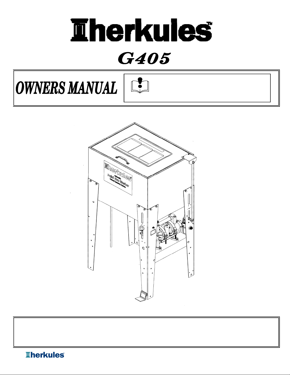
Herkules G405 User Manual
INSTRUCTIONS
Part# 1002750-04
8/21/2007
This manual contains important information concerning the
installation and operation of the gun washers listed above.
Read manual thoroughly and keep for future reference
Herkules Equipment Corporation 2760 Ridgeway Court Walled Lake, MI 48390-1662 USA
248-960-7100 800-444-4351 Fax 248 960-7109
Patents USA 7070167 4793369, 4960142, 5174317, 5193561, 5485860 Canada 1299468 & Patents Pending
website: www.herkules.us Made in the USA e-mail: info@herkules.us
Page 1 of 23
Table of Contents
Warnings ……………………………………………………………………………………………………………………… 3-4
Assembly Instructions ……………………………………………………………………………………………………….. 5-10
Model Information ……………………………………………………………………………………………………………. 11
Installation ………………………………………………………………………………………………………………….. 12
Operation ……………………………………………………………………………………………………………………. 13-14
Preventive Maintenance ………………………………………………………………………………………………………. 14
Troubleshooting ……………………………………………………………………………………………………………… 15
Drawings with part lists: …………………………………………………………………………………………………… 16-21
Notes ………………………………………………………………………………………………………………………….. 22
Warning Symbol Caution Symbol
WARNING
This symbol alerts you to the possibility of serious
injury or death if you do not follow the instructions.
Serial Number
Model Number
Purchase Date
Distributor
CAUTION
This symbol alerts you to the possibility of damage to
or destruction of equipment if you do not follow the
instructions.
PATENT NUMBERS
This product has patent protection under
one or more of the following patent num ber s :
7070167, 5485860, 5193561, 5174317
4960142, 4793369, 1299468
and Patents Pending
website: www. h erk u les . us
1002742
Page 2 of 23
Page 2 of 23
WARNING
EQUIPMENT MISUSE HAZARD
Equipment misuse can cause the equipment to rupture, malfunction, or start unexpectedly
and result in serious injury.
• This equipment is for professional use only.
• Read all instruction manuals, tags, and labels before operating the equipment.
• Use the equipment only for its intended use.
• Do not alter or modify this equipment.
• Do not exceed the maximum working pressure of the lowest rated system component.
• Do not operate the gun washer at a pressure above the maximum working pressure rating of the
gun(s) being cleaned.
• Route the hoses away from traffic areas, sharp edges, moving parts, and hot surfaces.
• Do not use the hoses to pull the equipment.
• Do not move pressurized equipment.
• Use fluids or solvents that are compatible with the equipment wetted parts. Read the fluid and
solvent manufacturer's warnings.
• Comply with all applicable local, state and national fire, electrical and other safety regulation.
PRESSURIZED EQUIPMENT HAZARD
Spray from hose leaks, ruptured components, or from operating the gun washer with an open lid
can splash fluid in the eyes or on the skin and cause serious injury.
• A safety device has been installed to shut off the pump when the gun washer lid is opened.
Do not tamper with or alter this device.
• Open the gun washer lid slowly.
• Do not prop the gun washer lid open with an object or by any other means.
• Do not stop or deflect fluid leaks with your hand, body, glove, or rag.
• Tighten all fluid connections before operating the equipment.
• Replace worn, damaged, or loose parts immediately.
Page 3 of 23
Page 3 of 23
WARNING
FIRE AND EXPLOSION HAZARD
Improper grounding, poor air ventilation, open flames, or sparks can cause a hazardous condition
and result in fire or explosion and serious injury.
• Ground the equipment. See Installation for grounding procedure.
• Provide fresh air ventilation to avoid the build up of flammable fumes from the cleaning solution.
• Extinguish all open flames or pilot lights in the gun washer area.
• Disconnect all electrical equipment in the gun washer area.
• Keep the gun washer area free of debris, including cleaning solutions, rags, and gasoline.
• Do not turn on any light switch in the gun washer area while operating or if fumes are present.
• Do not smoke in the gun washer area.
• Do not operate a gasoline engine in the gun washer area.
• Follow the gun manufacturer's solvent and other cleaning recommendations.
• Use solvent with the highest possible flash point.
•
correct the problem.
• Drain the cleaning solution into a proper storage container when gun washer(s) is not in use.
If there is any static sparking while using the equipment, stop operation immediately. Identify and
TOXIC FLUID HAZARD
Hazardous fluids or toxic fumes can cause serious injury or death if splashed in eyes or on the
skin, swallowed, or inhaled.
• Know the specific hazards of the fluid you are using. Read the fluid manufacturer's warnings.
• Store hazardous fluid in an approved container. Dispose of hazardous fluid according to all local, state
and national guidelines.
• Wear the appropriate protective clothing, gloves, eyewear and respirator.
• Pipe and dispose of the exhaust air safely. If diaphragm fails, the fluid may be exhausted along with
the air.
Page 4 of 23
Page 4 of 23
Assembly
r
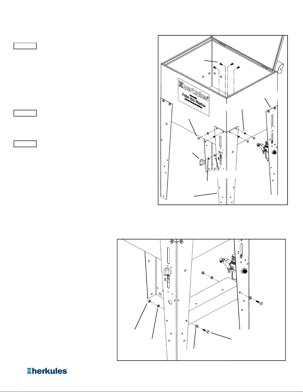
Stand and Pump Installation
STEP 1
Install the legs to the tank using (4) x Hex Bolt 1/4-20 x 1/2"
SS (1002751), (4) x Acorn Nut (008-244), (4) x Lock Washer
(85)and (4) x Nylon Washer (1002656) per leg (see fig.1).
Notes:
STEP 2
Timer Leg (See fig.1).
STEP 3
1. Filter/Regulator and Timer Leg Assemblies must be
positioned as shown in fig.1.
2. Opposite legs must have holes for mounting
rinse pump in correct orientation (see fig 3a).
Install the Timer Knob (M230-002) with Nylon Spacer
(M230-005) and Flat Washer #10 Zinc (002-161) to the
Install the Pump Bracket (1002747) to the legs using (2) x
Hex Bolt 1/4-20 x 1" (83), (2) x Flat Washer (001-705),
(2) x Lock Washer (85) and (2) x Hex Nut (84) (see fig.2).
Hex Bolt SS
1/4-20 x 1/2"
Acorn Nut
Timer Knob
Filter/Regulator Leg
Lock Washer
Nylon Space
Timer Leg
Flat Washer
fig.1
Hex Nut
Lock Washer
Flat Washer
Hex Bolt 1/4-20 x 1"
fig.2
Page 5 of 23
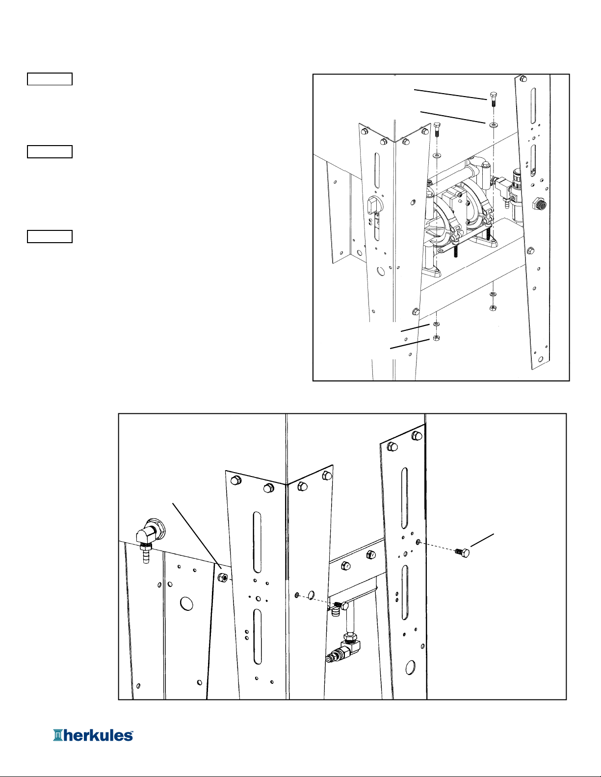
Assembly
fig.3
STEP 4
Install the Pump Assembly (12771) to the stand using
(2) x Hex Bolt 1/4-20 x 1" (83), (2) x Flat Washer
(001-705), (2) x Lock Washer (85) and (2) x Hex Nut
(84) (see fig.3).
STEP 5
Install the Rinse Pump Assembly (13638) to the stand using
(2) x Hex Bolt 1/4-20 x 1/2" (1002751), (2) x Lock Nuts
(005-130)(see fig.3a).
Fluid and Air Hose Connections
STEP 6
Make all necessary hose connections
(see fig 4-7).
Hex Bolt
1/4-20 x 1"
Flat Washer
Lock Washer
Hex Nut
fig.3a
Lock Nut
Hex Bolt
1/4-20 x 1/2"
Page 6 of 23
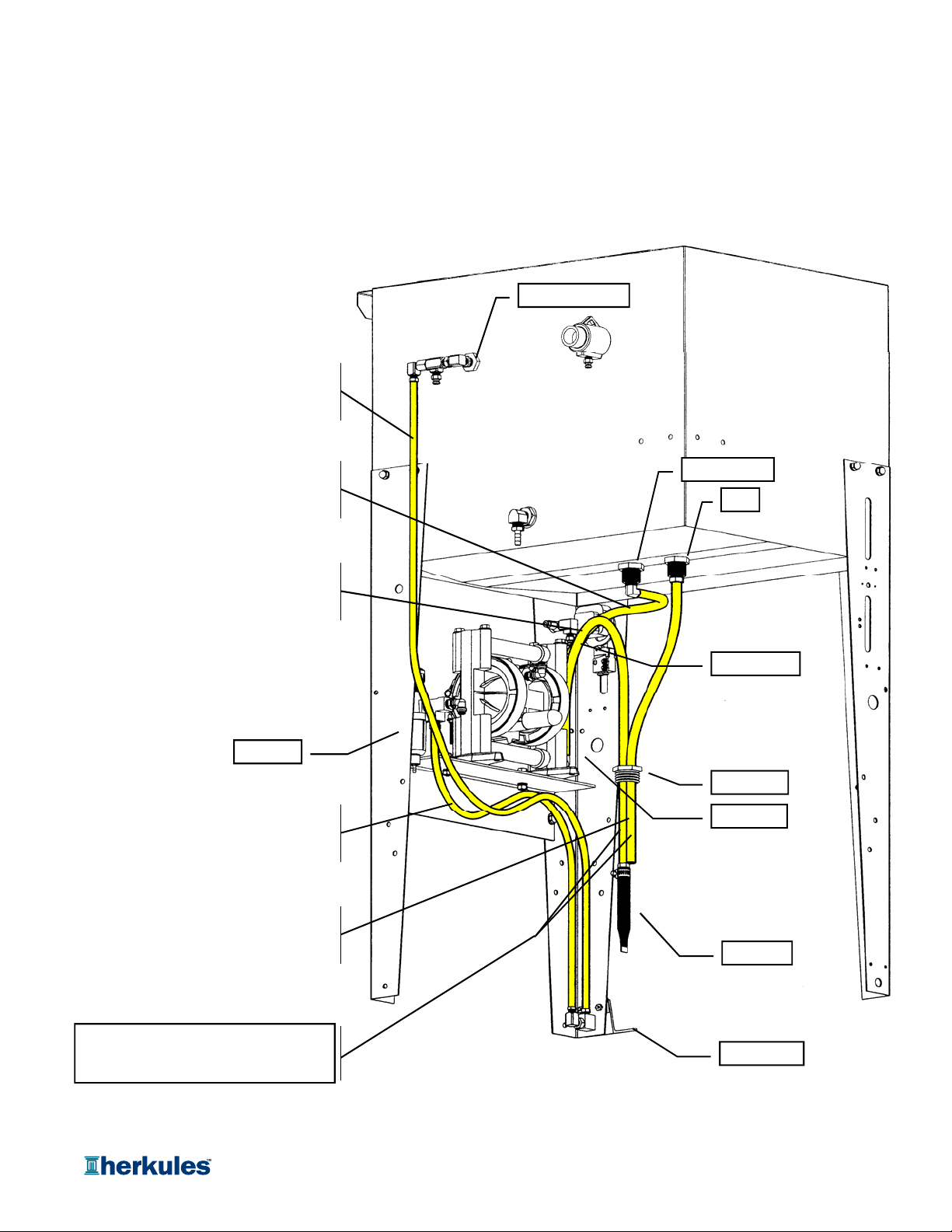
Fig.4 shows the unit without the rear left leg
1/2 OD Hose x 34
and excludes all hoses other than those
called out.
DO NOT heat hoses to install.
Test connection by pulling firmly on hose.
3/8" OD Hose x 50"
Pre-Installed at Foot Switch
Install to Brush Bulkhead Fitting
Assembly
Brush Bulkhead
1/2" OD Hose x 11"
Install to Pump Outlet Port
Install to Manifold Inlet Port
"
Install to Inlet Filter through Nylon Plug
Install to Pump Inlet Port
NOTE: Threads of the Nylon Plug must
face towards the Inlet Filter
Regulator
3/8" OD Hose x 23"
Pre-Installed at Foot Switch
Install to Air Out Fitting on Regulator
1/2" OD Hose x 22"
Install to Drain Port in Tank
No Installation on Opposite End
Manifold Inlet
Drain
"
Pump Outlet
Nylon Plug
Pump Inlet
Inlet Filter
securing Nylon Plug in can opening
Two (2) hoses are installed
into cleaning solution can
Foot Switch
fig.4
Page 7 of 23
 Loading...