

Herkules G202 User Manual
INSTRUCTIONS
Part# 1002759-08
4/7/2009
This manual contains important information concerning the
installation and operation of the gun washers listed above.
Read manual thoroughly and keep for future reference
Herkules Equipment Corporation 2760 Ridgeway Court Walled Lake, MI 48390-1662 USA
248-960-7100 800-444-4351 Fax 248 960-7109
Patents USA 7070167 4793369, 4960142, 5174317, 5193561, 5485860 Canada 1299468 & Patents Pending
website: www.herkules.us Made in the USA e-mail: info@herkules.us
Page 1 of 18

Table of Contents
Warnings ……………………………………………………………………………………………………………………… 3-4
Assembly Instructions ……………………………………………………………………………………………………….. 5
Model Information ……………………………………………………………………………………………………………. 6
Installation ………………………………………………………………………………………………………………….. 6
Operation ……………………………………………………………………………………………………………………. 7-8
Preventive Maintenance ………………………………………………………………………………………………………. 8
Troubleshooting ……………………………………………………………………………………………………………… 9
Drawings with part lists: …………………………………………………………………………………………………… 10-18
Warning Symbol Caution Symbol
WARNING
This symbol alerts you to the possibility of serious
injury or death if you do not follow the instructions.
Serial Number
Model Number
Purchase Date
Distributor
CAUTION
This symbol alerts you to the possibility of damage to
or destruction of equipment if you do not follow the
instructions.
PATENT NUMBERS
This product has patent protection under
one or more of the following patent num ber s :
7070167, 5485860, 5193561, 5174317
4960142, 4793369, 1299468
and Patents Pending
website: www. h erk u les . us
1002742
Page 2 of 18
Page 2 of 18
WARNING
EQUIPMENT MISUSE HAZARD
Equipment misuse can cause the equipment to rupture, malfunction, or start unexpectedly
and result in serious injury.
• This equipment is for professional use only.
• Read all instruction manuals, tags, and labels before operating the equipment.
• Use the equipment only for its intended use.
• Do not alter or modify this equipment.
• Do not exceed the maximum working pressure of the lowest rated system component.
• Do not operate the gun washer at a pressure above the maximum working pressure rating of the
gun(s) being cleaned.
• Route the hoses away from traffic areas, sharp edges, moving parts, and hot surfaces.
• Do not use the hoses to pull the equipment.
• Do not move pressurized equipment.
• Use fluids or solvents that are compatible with the equipment wetted parts. Read the fluid and
solvent manufacturer's warnings.
• Comply with all applicable local, state and national fire, electrical and other safety regulation.
PRESSURIZED EQUIPMENT HAZARD
Spray from hose leaks, ruptured components, or from operating the gun washer with an open lid
can splash fluid in the eyes or on the skin and cause serious injury.
• A safety device has been installed to shut off the pump when the gun washer lid is opened.
Do not tamper with or alter this device.
• Open the gun washer lid slowly.
• Do not prop the gun washer lid open with an object or by any other means.
• Do not stop or deflect fluid leaks with your hand, body, glove, or rag.
• Tighten all fluid connections before operating the equipment.
• Replace worn, damaged, or loose parts immediately.
Page 3 of 18
Page 3 of 18

WARNING
FIRE AND EXPLOSION HAZARD
Improper grounding, poor air ventilation, open flames, or sparks can cause a hazardous condition
and result in fire or explosion and serious injury.
• Ground the equipment. See Installation for grounding procedure.
• Provide fresh air ventilation to avoid the build up of flammable fumes from the cleaning solution.
• Extinguish all open flames or pilot lights in the gun washer area.
• Disconnect all electrical equipment in the gun washer area.
• Keep the gun washer area free of debris, including cleaning solutions, rags, and gasoline.
• Do not turn on any light switch in the gun washer area while operating or if fumes are present.
• Do not smoke in the gun washer area.
• Do not operate a gasoline engine in the gun washer area.
• Follow the gun manufacturer's solvent and other cleaning recommendations.
• Use solvent with the highest possible flash point.
•
correct the problem.
• Drain the cleaning solution into a proper storage container when gun washer(s) is not in use.
If there is any static sparking while using the equipment, stop operation immediately. Identify and
TOXIC FLUID HAZARD
Hazardous fluids or toxic fumes can cause serious injury or death if splashed in eyes or on the
skin, swallowed, or inhaled.
• Know the specific hazards of the fluid you are using. Read the fluid manufacturer's warnings.
• Store hazardous fluid in an approved container. Dispose of hazardous fluid according to all local, state
and national guidelines.
• Wear the appropriate protective clothing, gloves, eyewear and respirator.
• Pipe and dispose of the exhaust air safely. If diaphragm fails, the fluid may be exhausted along with
the air.
Page 4 of 18
Page 4 of 18
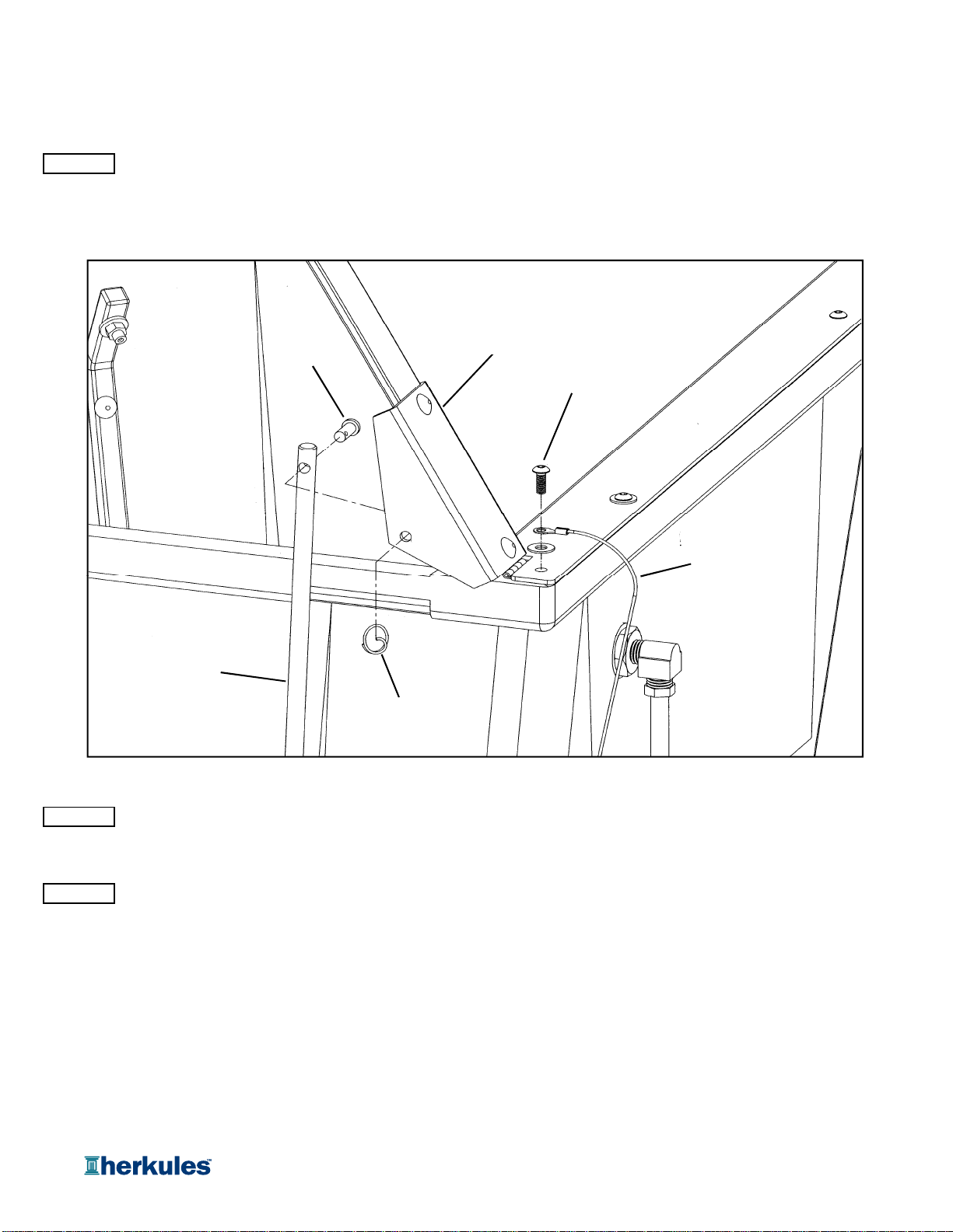
Assembly
Connecting lid rod and actuator linkage
STEP 1
Attach the lid rod to the lid bracket using the 1/4" clevis pin and circular cotter pin supplied (see fig.1).
NOTE: The lid rod installs to the back side of the lid bracket.
Grounding the lid
Lid rod
Clevis pin
Lid bracket
Lid screw
Ground wire
Cotter Pin
fig.1
STEP 2
Using an 1/8" allen wrench, remove the back right lid screw. Connect the ground wire (with an aluminum
terminal attached to both ends) from the pump to the lid screw and reconnect it to the tub (see fig.1).
STEP 3
Proceed to Installation on page 6.
Page 5 of 18

Model Information
)
()
A
r
r
p
g
B
A
D
NOTE: Dimensions listed are overall measurements.
Model Weight
Two gun, two cup paint gun washer equipped with
G202
diaphragm pump, filter-regulator, timer, manual brush
clean and foot pedal for solvent and water based paints.
Description
lbs/(kg)
68
(31)
C
Dimensions in./(mm
BCD
46.25 22.6 25 21.25
(1175) (574) (635) (635)
Installation
Installing the Gun Washe
1) Place gun washer on a level surface in a properly
ventilated paint mixing room or paint booth.
Grounding the Gun Washe
1) Connect the ground wire on the gun washer’s pump to a
true earth ground.
2) Ground all equipment used or located in the gun washer
area.
Connecting the Air Line
1) Install a 1/4 in. npt male coupler, that is compatible with
the quick disconnect of your air supply line, into the air
supply port of the filter/regulator located on the right rear
leg (see fig.2).
2) Connect air line with at least 75 psi to the coupler.
Filter/regulator is preset. Do not adjust.
Air supply
port
fig.2
Page 6 of 18
 Loading...