

Herkules 11981 INSTALLATION INSTRUCTIONS

Part# 1002389
Y
7/13/2005
INSTALLATION INSTRUCTIONS
11981 TIMED DIAPHRAGM PUMP CONVERSION ASSEMBL
FOR CONVERTING A TIMED GUN WASHER FROM
A PISTON PUMP TO A DIAPHRAGM PUMP
Plastic Bag Contents Assembling Diaphragm Pump Housing onto
Gun Washer
• Installation Instructions
• 2 nuts, 2 flat washers, 2 lock washers, and 1) Loosely mount the 11981 diaphragm pump
2 nylon spacers assembly onto the gun washer stand.
• Solvent intake filter
• 2 steel tubes with flare nuts. Note: The timer knob is at the front of the
• Operating instructions decal for washer lid housing assembly and the filter and air
• Owner's Manual: GW/R-T-OM tubing lines are at the rear.
Removal of Gun Washer's Piston Pump
2) Place the two nylon spacers over the housing
Assembly bolts and insert into the gun washer frame
holes. Place flat washer, then lock washer,
1) Disconnect shop air line from Gun Washer. then nut onto the 1" bolt. Finger tighten only.
2) Drain and clean inside of tub.
3) Remove filter from inside tub. 3) Connect the steel tubes between the pump and
4) Disconnect ground wire from pump. the tub. Use finger force to engage threads on
5) Disconnect the solvent tube fittings at the tub flare nuts.
inlet and outlet locations.
6) Cut or disconnect the ties holding the grey a) Connect the shorter, 3/8" diameter tube
timer tube to the Gun Washer frame. between the "Material Outlet" of the pump
7) Remove the two plastic air lines on the safety and the upper bulkhead of the tub. Finger
shut-off switch at the lid. tighten.
Note: To remove air lines use a fingernail or
b) Connect the longer, 1/2" diameter tube
screw driver to press in brass collar on the between the "Material Inlet" of the pump to
roller switch, then pull on tubing to remove. the lower bulkhead of the tub. Finger
tighten.
8) Remove piston pump saddle clamp from Gun
Washer frame. Dispose of the entire piston
c) When the housing and solvent tubes are
pump assembly, including the timer tube. aligned, tighten the four flare nuts
4) Tighten the diaphragm pump housing's two
1/4-20 x 1" hex head bolts, washers, and nuts
as loosely assembled in step 1.
Herkules Equipment Corporation 2760 Ridgeway Court Walled Lake, MI 48390-1662 USA
248-960-7100
1-800-444-4351 Fax 248-960-7109
www.herkulesequipment.com
■ info@herkules.us
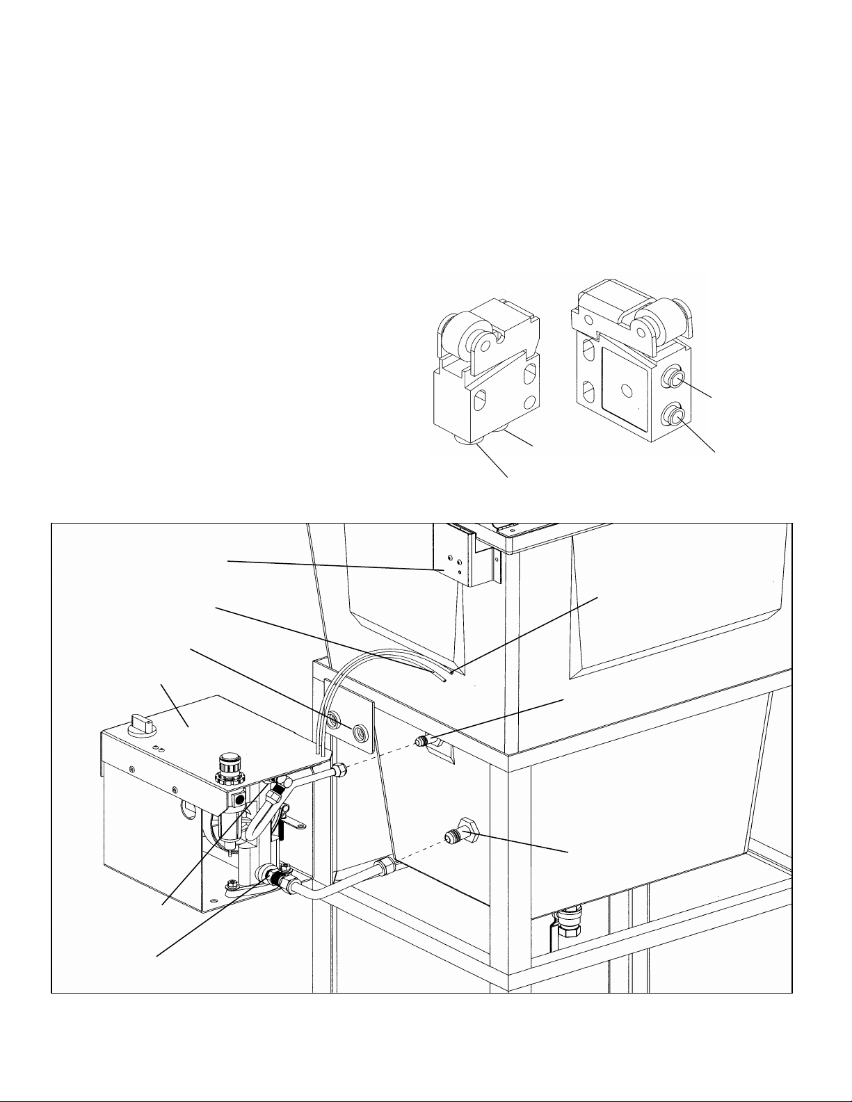
5) Connect the blue plastic air tubing running from 7) Connect a shop air line of 65-120 psi. The paint
the housing (timer cut off switch) to the in port gun washer's filter-regulator is factory preset
of the safety shut-off switch at the lid. The and locked at 65 psi. DO NOT ATTEMPT TO
switch is shielded by an aluminum panel. See CHANGE THIS SETTING.
drawings. Press tubing in through the collar
until seated in the black, roller safety shut-off
8) Connect the coiled ground wire attached at the
switch. The hose must bottom out in the front of the pump to the shop's ground. Route
switch. Then, pull firmly to test for a tight the wire through the housing and out the back.
connection.
In the same way, connect the black plastic air
tubing line running from housing (pump) to the
out port of the safety shut-off switch at the lid.
Again press tubing in through the collar until
seated in the roller safety shut-off switch. The
hose must bottom out in the switch. Then, pull
firmly to test for a tight connection.
6) Install your own 1/4" male connector into the
filter-regulator inlet at the back of the pump
housing. IMPORTANT: Hand tighten your air
coupler male connector into the filter-regulator
inlet. Then, wrench tighten it 1/4 turn only.
Safety shut off switch
Black air tubing
Nylon spacer
#M1C
IN PORT
OUT PORT
#M1
OUT PORT
IN PORT
Blue air tubing
Pump housing
Material outlet
Material inlet
Upper bulkhead
Lower bulkhead
 Loading...