

Herkules 10792 INSTALLATION INSTRUCTIONS

V
Equipment Corporation
Manufacturing Systems and Equipment for the Automotive and Industrial Markets
Part# 1001483
6-21-01 TN
TM
CRUSHING
HANDLING
LIFTINGCURING
WASHING
ACUUMING
This manual contains important information
concerning the installation and operation of the
equipment listed below. Read manual
INSTRUCTIONS thoroughly and keep for future reference.
Herkules Equipment Corporation 2760 Ridgeway Court Walled Lake, MI 48390-1662 USA
248-960-7100 1-800-444-4351 Fax 248-960-7109
9
8
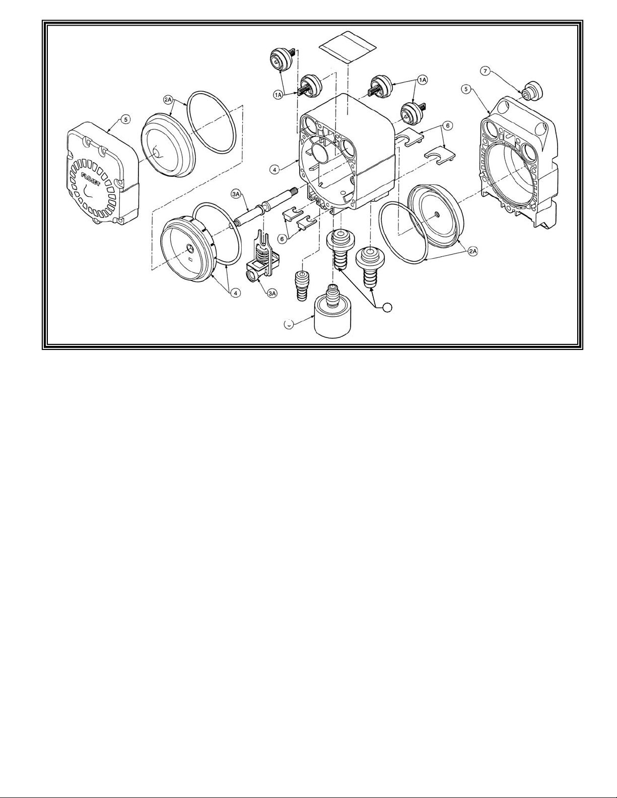
Item Description
1A. Check Valve
2A. Diaphragm & O-ring
3A. Slide Valve Assembly
4. Flange & O-ring
5. End Caps
6. Retaining Clips
7. Rubber Grommet
8. Muffler
9. Suction/Discharge Fitting
Disassemble Procedure
First remove all air in lines and suction/discharge
fittings from the pump. This is accomplished by using
a flat bladed screwdriver to slide the retaining clip
away from the air in and suction/discharge fittings and
pulling the fittings away from the pump body. Now
remove the
muffler by sliding the retaining clip away from the
muffler base and pulling the muffler out of the pump
body.
Using a Phillips screwdriver remove the seven screws
from the front-end cap followed by the seven screws
from the rear end cap. With the front end facing up
and the rear end facing down on the workbench,
position a flat bladed screwdriver into the slot located
above the muffler port and just below the pad marked
Air/CO
can be removed by placing the flat bladed screwdriver
under the fully opened port retaining clip and lifting off.
Note the position of the suction and discharge valves
before removing them from the pump body. The first
diaphragm is removed from the pump shaft by
unscrewing in a counter clockwise direction. The
second diaphragm is removed by the flat tip of a
screwdriver into he exposed slot at the end of the shaft
and unscrewing the diaphragm from the shaft. To
remove the flange housing, place the tip of a flat
bladed screwdriver into the air bleed hole on the lower
side of the flange housing and lift up the lower end
separating the flange housing from the pump body.
The slide valve assembly and the pump shaft can be
removed by simply pulling them from the pump body.
The pump shaft then can be removed from the slide
valve yoke assembly.
2 and lift off the front end cap. The rear end cap
Reassemble Procedure
Assemble the slide valve and the pump shaft with the
yoke placed between the two bumpers on the pump
shaft. Install the slide valve/pump shaft assembly into
the pump body making sure the o-rings in the slide
valve are in place. To install the flange housing,
prelube the o-ring with Parker Super “O” Lube and
install on flange housing and place housing over the
pump body aligning the flange housing with the pump
body ribs pressing it into place.
Install the first diaphragm and o-ring onto the pump
shaft threading it onto the shaft using a flat blade
screwdriver to hold the pump shaft until the diaphragm
is tight. Install the second diaphragm and o-ring onto
he pump shaft turning clockwise until tight.
Install the suction valves with springs facing into the
pump body and the discharge valves with the springs
facing out. See arrows on pump rear end cap below
suction and discharge ports.
Install the port retaining clips (large) into the pump end
cap (mounting base) and install the seven Phillips
screws into the pump body and cross tighten until
snug and the cross torque to 22-24 inch pounds.
Install port retaining clips (small) into the pump body,
tabs facing out, position the front end cap and install
the seven Phillips screws into the pump body and
cross tighten until snug and the cross torque to 22-24
inch pounds.
Install the muffler in the center port by pushing it in
and sliding the retaining clip into place. Install the
suction and discharge and the air in port fitting and
slide the retaining clips into place. Check for leaks.
 Loading...