

Page 1
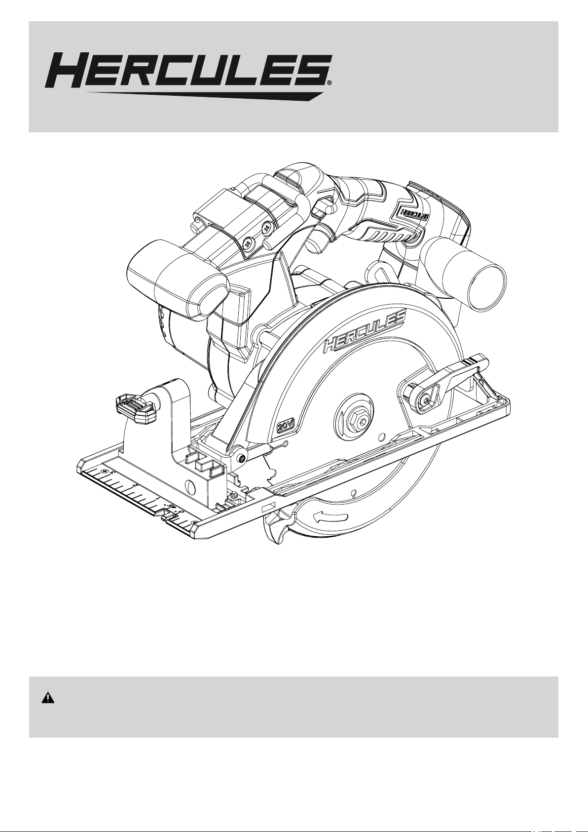
Owner’s Manual &
Safety Instructions
19k
Model
HC72B
6-1/2″ Cordless Circular Saw
WARNING: To prevent serious injury, User must read and
understand Owner’s Manual. SAVE THIS MANUAL.
When unpacking, make sure that the product is intact and
undamaged. If any parts are missing or broken, please call
1-888-866-5797 as soon as possible. Reference 64984.
Page 2

IMPORTANT SAFETY INFORMATION
General Power Tool Safety Warnings
Read all safety warnings, instructions, illustrations
and specifications provided with this power tool.
Failure to follow all instructions listed below may
result in electric shock, fire and/or serious injury.
Save all warnings and instructions
for future reference.
The term “power tool” in the warnings refers
to your mains-operated (corded) power tool or
battery-operated (cordless) power tool.
1. Work area safety
a. Keep work area clean and well lit.
Cluttered or dark areas invite accidents.
b. Do not operate power tools in explosive
atmospheres, such as in the presence of
flammable liquids, gases or dust. Power tools
create sparks which may ignite the dust or fumes.
c. Keep children and bystanders away
while operating a power tool. Distractions
can cause you to lose control.
2. Electrical safety
a. Power tool plugs must match the outlet.
Never modify the plug in any way. Do not use
any adapter plugs with earthed (grounded)
power tools. Unmodified plugs and matching
outlets will reduce risk of electric shock.
b. Avoid body contact with earthed or grounded
surfaces, such as pipes, radiators, ranges
and refrigerators. There is an increased risk of
electric shock if your body is earthed or grounded.
c. Do not expose power tools to rain or wet
conditions. Water entering a power tool
will increase the risk of electric shock.
d. Do not abuse the cord. Never use the cord
for carrying, pulling or unplugging the power
tool. Keep cord away from heat, oil, sharp
edges or moving parts. Damaged or entangled
cords increase the risk of electric shock.
e. When operating a power tool outdoors,
use an extension cord suitable for outdoor
use. Use of a cord suitable for outdoor
use reduces the risk of electric shock.
f. If operating a power tool in a damp location
is unavoidable, use a ground fault circuit
interrupter (GFCI) protected supply. Use of
a GFCI reduces the risk of electric shock.
3. Personal safety
a. Stay alert, watch what you are doing and
use common sense when operating a
power tool. Do not use a power tool while
you are tired or under the influence of
drugs, alcohol or medication. A moment
of inattention while operating power tools
may result in serious personal injury.
b. Use personal protective equipment. Always
wear eye protection. Protective equipment
such as dust mask, non-skid safety shoes, hard
hat, or hearing protection used for appropriate
conditions will reduce personal injuries.
c. Prevent unintentional starting. Ensure the
switch is in the off-position before connecting
to power source and/or battery pack, picking
up or carrying the tool. Carrying power tools
with your finger on the switch or energizing power
tools that have the switch on invites accidents.
d. Remove any adjusting key or wrench
before turning the power tool on. A wrench
or a key left attached to a rotating part of the
power tool may result in personal injury.
e. Do not overreach. Keep proper footing and
balance at all times. This enables better control
of the power tool in unexpected situations.
f. Dress properly. Do not wear loose clothing or
jewelry. Keep your hair, clothing and gloves
away from moving parts. Loose clothes, jewelry
or long hair can be caught in moving parts.
g. If devices are provided for the connection of
dust extraction and collection facilities, ensure
these are connected and properly used. Use of
dust collection can reduce dust-related hazards.
h. Do not let familiarity gained from frequent
use of tools allow you to become
complacent and ignore tool safety principles.
A careless action can cause severe
injury within a fraction of a second.
i. Only use safety equipment that has been
approved by an appropriate standards agency.
Unapproved safety equipment may not provide
adequate protection. Eye protection must be
ANSI-approved and breathing protection
must be NIOSH-approved for the
specific hazards in the work area.
j. Avoid unintentional starting.
Prepare to begin work before turning on the tool.
k. Do not lay the tool down until it has come to
a complete stop. Moving parts can grab the
surface and pull the tool out of your control.
Page 2 For technical questions, please call 1-888-866-5797. Item 64984
Page 3

l. When using a handheld power tool,
maintain a firm grip on the tool with both
hands to resist starting torque.
m. Do not depress the spindle lock when
starting or during operation.
n. Do not leave the tool unattended when
it is plugged into an electrical outlet the
Battery Pack is connected. Turn off the
tool, and unplug it from its electrical outlet
remove the Battery Pack before leaving.
o. This product is not a toy.
Keep it out of reach of children.
p. People with pacemakers should consult their
physician(s) before use. Electromagnetic fields in
close proximity to heart pacemaker could cause
pacemaker interference or pacemaker failure.
In addition, people with pacemakers should:
• Avoid operating alone.
• Do not use with Trigger locked on.
• Properly maintain and inspect to avoid
electrical shock.
• Properly ground power cord.
Ground Fault Circuit Interrupter (GFCI)
should also be implemented – it prevents
sustained electrical shock.
q. The warnings, precautions, and instructions
discussed in this instruction manual cannot
cover all possible conditions and situations
that may occur. It must be understood by the
operator that common sense and caution are
factors which cannot be built into this product,
but must be supplied by the operator.
4. Power tool use and care
a. Do not force the power tool. Use the correct
power tool for your application. The correct
power tool will do the job better and safer
at the rate for which it was designed.
b. Do not use the power tool if the switch
does not turn it on and off. Any power
tool that cannot be controlled with the switch
is dangerous and must be repaired.
c. Disconnect the plug from the power
source and/or remove the battery pack,
if detachable, from the power tool before
making any adjustments, changing
accessories, or storing power tools.
Such preventive safety measures reduce the
risk of starting the power tool accidentally.
d. Store idle power tools out of the reach of
children and do not allow persons unfamiliar
with the power tool or these instructions
to operate the power tool. Power tools are
dangerous in the hands of untrained users.
e. Maintain power tools and accessories.
Check for misalignment or binding of moving
parts, breakage of parts and any other
condition that may affect the power tool’s
operation. If damaged, have the power tool
repaired before use. Many accidents are
caused by poorly maintained power tools.
f. Keep cutting tools sharp and clean. Properly
maintained cutting tools with sharp cutting edges
are less likely to bind and are easier to control.
g. Use the power tool, accessories and tool bits
etc. in accordance with these instructions,
taking into account the working conditions
and the work to be performed. Use of the
power tool for operations different from those
intended could result in a hazardous situation.
h. Keep handles and grasping surfaces
dry, clean and free from oil and grease.
Slippery handles and grasping surfaces
do not allow for safe handling and control
of the tool in unexpected situations.
5. Service
a. Have your power tool serviced by a
qualified repair person using only identical
replacement parts. This will ensure that
the safety of the power tool is maintained.
b. Maintain labels and nameplates on the tool.
These carry important safety information.
If unreadable or missing, contact
Harbor Freight Tools for a replacement.
6. Circular Saw Safety Warnings
- Cutting procedures
a. DANGER: Keep hands away from
cutting area and the blade. Keep your
second hand on auxiliary handle, or
motor housing. If both hands are holding
the saw, they cannot be cut by the blade.
b. Do not reach underneath the workpiece.
The guard cannot protect you from
the blade below the workpiece.
c. Adjust the cutting depth to the thickness of
the workpiece. Less than a full tooth of the blade
teeth should be visible below the workpiece.
d. Never hold the workpiece in your hands or
across your leg while cutting. Secure the
workpiece to a stable platform. It is important
to support the work properly to minimise body
exposure, blade binding, or loss of control.
e. Hold the power tool by insulated gripping
surfaces, when performing an operation where
the cutting tool may contact hidden wiring or
its own cord. Contact with a “live” wire will also
make exposed metal parts of the power tool “live”
and could give the operator an electric shock.
f. When ripping, always use a rip fence or
straight edge guide. This improves the accuracy
of cut and reduces the chance of blade binding.
Page 3For technical questions, please call 1-888-866-5797.Item 64984
Page 4

g. Always use blades with correct size and shape
(diamond versus round) of arbor holes. Blades
that do not match the mounting hardware of the
saw will run off-center, causing loss of control.
h. Never use damaged or incorrect blade
washers or bolt. The blade washers and
bolt were specially designed for your saw, for
optimum performance and safety of operation.
7. Kickback causes and related warnings
- kickback is a sudden reaction to a pinched,
jammed or misaligned saw blade, causing
an uncontrolled saw to lift up and out of
the workpiece toward the operator;
- when the blade is pinched or jammed
tightly by the kerf closing down, the blade
stalls and the motor reaction drives the
unit rapidly back toward the operator;
- if the blade becomes twisted or misaligned
in the cut, the teeth at the back edge of the
blade can dig into the top surface of the
wood causing the blade to climb out of the
kerf and jump back toward the operator.
Kickback is the result of saw misuse and/or incorrect
operating procedures or conditions and can be avoided
by taking proper precautions as given below.
a. Maintain a firm grip with both hands on the
saw and position your arms to resist kickback
forces. Position your body to either side
of the blade, but not In line with the blade.
Kickback could cause the saw to jump backwards,
but kickback forces can be controlled by the
operator, if proper precautions are taken.
b. When blade is binding, or when interrupting
a cut for any reason, release the trigger
and hold the saw motionless in the material
until the blade comes to a complete stop.
Never attempt to remove the saw from
the work or pull the saw backward while
the blade is in motion or kickback may
occur. Investigate and take corrective actions
to eliminate the cause of blade binding.
c. When restarting a saw in the workpiece,
centre the saw blade in the kerf so that the
saw teeth are not engaged into the material.
If a saw blade binds, it may walk up or kickback
from the workpiece as the saw is restarted.
d. Support large panels to minimise the risk of
blade pinching and kickback. Large panels tend
to sag under their own weight. Supports must
be placed under the panel on both sides, near
the line of cut and near the edge of the panel.
e. Do not use dull or damaged blades.
Unsharpened or improperly set blades
produce narrow kerf causing excessive
friction, blade binding and kickback.
f. Blade depth and bevel adjusting locking
levers must be tight and secure before
making the cut. If blade adjustment shifts while
cutting, it may cause binding and kickback.
g. Use extra caution when sawing into existing
walls or other blind areas. The protruding
blade may cut objects that can cause kickback.
8. Lower guard function
a. Check the lower guard for proper closing
before each use. Do not operate the saw if the
lower guard does not move freely and close
instantly. Never clamp or tie the lower guard
into the open position. If the saw is accidentally
dropped, the lower guard may be bent. Raise the
lower guard with the retracting handle and make
sure it moves freely and does not touch the blade
or any other part, in all angles and depths of cut.
b. Check the operation of the lower guard
spring. If the guard and the spring are
not operating properly, they must be
serviced before use. Lower guard may
operate sluggishly due to damaged parts,
gummy deposits, or a build-up of debris.
c. The lower guard may be retracted manually
only for special cuts such as “plunge cuts”
and “compound cuts”. Raise the lower guard
by the retracting handle and as soon as the
blade enters the material, the lower guard
must be released. For all other sawing, the
lower guard should operate automatically.
d. Always observe that the lower guard
is covering the blade before placing
the saw down on bench or floor. An
unprotected, coasting blade will cause the
saw to walk backwards, cutting whatever is
in its path. Be aware of the time it takes for
the blade to stop after switch is released.
9. Riving knife function
a. Use the appropriate saw blade for the riving
knife. For the riving knife to function, the body
of the blade must be thinner than the riving
knife and the cutting width of the blade must be
wider than the thickness of the riving knife.
b. Adjust the riving knife as described in
this instruction manual. Incorrect spacing,
positioning and alignment can make the riving
knife ineffective in preventing kickback.
c. Always use the riving knife except when
plunge cutting. The riving knife must be
replaced after plunge cutting. The riving
knife causes interference during plunge
cutting and can create kickback.
d. For the riving knife to work, it must be engaged
in the workpiece. The riving knife is ineffective
in preventing kickback during short cuts.
e. Do not operate the saw if the riving
knife is bent. Even a light interference
can slow the closing rate of a guard.
Page 4 For technical questions, please call 1-888-866-5797. Item 64984
Page 5

10. Battery tool use and care
a. Prevent unintentional starting. Ensure the
switch is in the off-position before connecting
to battery pack, picking up or carrying the
power tool. Carrying the power tool with your
finger on the switch or energizing power tool
that have the switch on invites accidents.
b. Disconnect the battery pack from the
power tool before making any adjustments,
changing accessories, or storing power tool.
Such preventive safety measures reduce the
risk of starting the power tool accidentally.
c. Recharge only with the charger specified by
the manufacturer. A charger that is suitable
for one type of battery pack may create a risk
of fire when used with another battery pack.
d. Use power tools only with specifically
designated battery packs. Use of any other
battery packs may create a risk of injury and fire.
e. When battery pack is not in use, keep it away
from other metal objects, like paper clips,
coins, keys, nails, screws or other small metal
objects, that can make a connection from
one terminal to another. Shorting the battery
terminals together may cause burns or a fire.
f. Under abusive conditions, liquid may be
ejected from the battery; avoid contact.
If contact accidentally occurs, flush with
water. If liquid contacts eyes, additionally
seek medical help. Liquid ejected from the
battery may cause irritation or burns.
g. Do not use a battery pack or power tool that
is damaged or modified. Damaged or modified
batteries may exhibit unpredictable behavior
resulting in fire, explosion or risk of injury.
h. Do not expose a battery pack or power tool to
fire or excessive temperature. Exposure to fire
or temperature above 265°F may cause explosion.
i. Follow all charging instructions and do
not charge the battery pack or power tool
outside of the temperature range specified
in the instructions. Charging improperly or at
temperatures outside of the specified range may
damage the battery and increase the risk of fire.
j. Have servicing performed by a qualified
repair person using only identical
replacement parts. This will ensure that
the safety of the product is maintained.
k. Do not modify or attempt to repair the power
tool or the battery pack except as indicated
in the instructions for use and care.
l. The battery Charger gets hot during
use. The Charger’s heat can build up
to unsafe levels and create a fire
hazard if it does not receive adequate
ventilation, due to an electrical fault, or if it is used
in a hot environment. Do not place the Charger
on a flammable surface. Do not obstruct any
vents on the Charger. Especially avoid placing
the Charger on carpets and rugs; they are not
only flammable, but they also obstruct vents
under the Charger. Place the Charger on a
stable, solid, nonflammable surface (such as a
stable metal workbench or concrete floor) at least
1 foot away from all flammable objects, such as
drapes or walls. Keep a fire extinguisher and a
smoke detector in the area. Frequently monitor
the Charger and Battery Pack while charging.
m. Charge Battery Pack using Hercules 20V
Lithium Battery Charger only (sold separately).
11. Lithium Battery Safety Warnings
LITHIUM BATTERIES STORE
A LARGE AMOUNT OF ENERGY AND
WILL VENT FIRE OR EXPLODE
IF MISTREATED:
a. Keep Battery Pack dry.
B. DO NOT DO ANY OF THE FOLLOWING
TO THE BATTERY PACK:
• Open,
• Drop,
• Short-circuit,
• Puncture,
• Incinerate, or
• Expose to temperatures greater than 265°F.
c. Charge Battery Pack only according
to its Charger’s instructions.
d. Inspect Battery Pack before every use;
do not use or charge if damaged.
12. Vibration Safety
This tool vibrates during use.
Repeated or long-term exposure to vibration may
cause temporary or permanent physical injury,
particularly to the hands, arms and shoulders.
To reduce the risk of vibration-related injury:
a. Anyone using vibrating tools regularly or for
an extended period should first be examined
by a doctor and then have regular medical
check-ups to ensure medical problems are not
being caused or worsened from use. Pregnant
women or people who have impaired blood
circulation to the hand, past hand injuries,
nervous system disorders, diabetes, or
Raynaud’s Disease should not use this tool.
If you feel any symptoms related to vibration
(such as tingling, numbness, and white or blue
fingers), seek medical advice as soon as possible.
b. Do not smoke during use. Nicotine reduces
the blood supply to the hands and fingers,
increasing the risk of vibration-related injury.
Page 5For technical questions, please call 1-888-866-5797.Item 64984
Page 6

c. Wear suitable gloves to reduce the
vibration effects on the user.
d. Use tools with the lowest vibration
when there is a choice.
e. Include vibration-free periods each day of work.
f. Grip tool as lightly as possible (while still keeping
safe control of it). Let the tool do the work.
g. To reduce vibration, maintain the tool as
explained in this manual. If any abnormal
vibration occurs, stop use immediately.
Grounding Instructions
Extension cords must not be used with this
item’s Charger.
Warning Symbols and Definitions
V
A
n0 xxxx/min.
Symbology
Volts
Direct Current
Amperes
No Load Revolutions per Minute (RPM)
WARNING marking concerning Risk
of Eye Injury. Wear ANSI-approved
safety goggles with side shields.
Read the manual before set-up and/or use.
This is the safety alert symbol. It is used to
alert you to potential personal injury hazards.
Obey all safety messages that follow this symbol to
avoid possible injury or death.
Indicates a hazardous
situation which, if not
avoided, will result in death or serious injury.
Indicates a hazardous
situation which, if not
avoided, could result in death or serious injury.
Indicates a hazardous
situation which, if not
avoided, could result in minor or moderate injury.
Addresses practices not
related to personal injury.
SPECIFICATIONS
Battery Type 20V Li-Ion Hercules Battery
Keep hands clear of fence area.
DANGER marking concerning
Risk of Amputation.
Keep hands well clear of cutting area.
Charge on fireproof surface only.
Spindle No Load Speed 5,000 RPM
Max. Accessory Diameter
Arbor 5/8" Round
Max. Depth of Cut 45°: 1-5/8″, 90°: 2-3/16″
Page 6 For technical questions, please call 1-888-866-5797. Item 64984
6-1/2"
Page 7

FUNCTIONAL DESCRIPTION
Trigger Lock
Trigger
Handle
Dust
Port
Angle Gauge
Lock Knob
Angle
Gauge
Saw Blade
Upper
Guard
Saw
Blade
Bolt
Lower
Guard
Lever
Lower
Guard
Outer Flange
Page 7For technical questions, please call 1-888-866-5797.Item 64984
Page 8

OPERATION
Read the ENTIRE IMPORTANT SAFETY
INFORMATION section at the beginning of
this manual including all text under
subheadings therein before set up or use
TO PREVENT SERIOUS INJURY: DO NOT
OPERATE WITH ANY GUARD DISABLED,
DAMAGED, OR REMOVED. Moving guards
must move freely and close instantly.
.
Tool Set Up
TO PREVENT SERIOUS INJURY FROM ACCIDENTAL
OPERATION: Release the Trigger and remove the
Battery Pack before performing any procedure in
this section.
Note: For additional information regarding the
parts listed in the following pages, refer to the
Assembly Diagram near the end of this manual.
Replacing the Blade
1. Push and hold Spindle Lock, located above
Upper Guard, to keep Spindle from rotating.
2. Use a hex key to loosen (clockwise) and remove
Saw Blade Bolt. Remove Outer Flange.
3. Use the Lower Guard Lever to pull Lower Guard
all the way up into Upper Guard. While holding
Lower Guard in upward position, remove old
blade if needed and install new Saw Blade.
WARNING! Blade must be rated to at least 5,000 RPM.
Note: Install the new Saw Blade with its
teeth and its arrow pointing in the same
direction as the Lower Guard’s arrow.
4. Replace Outer Flange on Spindle with the
cupped side towards the blade, then tighten the
Blade Bolt by turning counterclockwise.
Depth Adjustment
1. Push the Depth Gauge Lever down to unlock.
2. Hold Base Plate down with one hand and
raise or lower Saw with the other hand until
the Blade is at the desired depth of cut,
using the Depth Gauge as a guide.
3. Pull Depth Gauge Lever up to lock.
WARNING! To reduce the risk of Serious Injury:
Depth of cut must be adjusted to just clear the workpiece.
Angle Adjustment
1. Loosen Angle Gauge Lock Knob.
2. Adjust Base Plate to desired angle between
0° and 45°, using the Angle Gauge as a guide.
3. Tighten Angle Gauge Lock Knob.
Rip Fence Installation and Use
1. Loosen Rip Fence Lock Knob.
2. Slide Rip Fence through slots on Base Plate.
3. Adjust Rip Fence, then tighten the Fence Lock Knob.
Workpiece and Work Area Set Up
1. Workpiece selection:
a. Workpiece must be free of foreign
objects and loose knots.
b. Do not use to cut logs, tree limbs,
or uneven lumber.
c. Wet lumber, green (unseasoned) lumber,
and pressure treated lumber all have an
increased potential for kickback and should
only be cut with a blade designed for cutting
that lumber. Wear a NIOSH-approved
respirator and have appropriate ventilation
whenever cutting pressure treated lumber.
2. Designate a work area that is clean and well-lit.
The work area must not allow access by children
or pets to prevent distraction and injury.
3. Secure loose workpieces using a vise or clamps
(not included) to prevent movement while working.
4. Verify that there are no utility lines or
hardware in or near the workpiece.
This is especially critical for plunge cuts.
5. Connect a dust collection system
(sold separately) to the Dust Port.
Charging
Refer to Hercules charger manual for instructions on how
to properly charge a Hercules battery (sold separately).
General Operation
1. Make all necessary adjustments to the Circular Saw.
2. Make sure that all guards are in place in
proper working order and that all adjustment
knobs are tight before operation.
3. Connect a 20V Hercules battery (sold
separately) to back of handle.
4. Firmly grip the Main Handle with one hand and
the Auxiliary Handle with the other hand.
5. Press and hold Trigger Lock, then the
Trigger to turn on the Circular Saw.
6. Release Trigger Lock.
7. Allow the Saw Blade to reach full speed before
feeding Saw Blade into the workpiece.
8. Make straight cuts only. DO NOT twist Saw while
cutting. If this occurs, the Saw Blade will “bind” in
the workpiece causing kickback, potential injury,
and/or damage to the workpiece and Circular Saw.
9. Do not force the Circular Saw to cut faster
than it is designed to cut. Feed the Saw
Blade gradually into the workpiece.
10. Release Trigger if the Saw Blade is to be backed
out of an uncompleted cut. Wait until the Saw
Blade stops spinning before removing the Saw.
Do not press against the Saw Blade to stop it.
11. Once the cutting job is completed, release the
Trigger and wait until the Saw Blade stops spinning.
Page 8 For technical questions, please call 1-888-866-5797. Item 64984
Page 9

12. Disconnect battery by pressing down on release
button and removing from back of handle.
13. Clean, then store the tool indoors
out of children’s reach.
MAINTENANCE AND SERVICING
Procedures not specifically explained
in this manual must be performed
only by a qualified technician.
TO PREVENT SERIOUS INJURY FROM ACCIDENTAL
OPERATION: Release the Trigger and remove the
Battery Pack before performing any procedure in
this section.
TO PREVENT SERIOUS INJURY FROM TOOL
FAILURE:
Do not use damaged equipment.
If abnormal noise or vibration occurs, have
the problem corrected before further use.
Cleaning, Maintenance,
and Lubrication
1. BEFORE EACH USE, inspect the general
condition of the tool. Check for:
• leaking, swollen, or cracked battery pack,
• loose hardware
• misalignment or binding of moving parts
• cracked or broken parts
• damaged electrical wiring
• any other condition that may
affect its safe operation.
2. AFTER USE, wipe external surfaces
of the tool with clean cloth.
3. Li-Ion BATTERY MUST BE RECYCLED OR
DISPOSED OF PROPERLY.
Do not short, incinerate or open battery.
4. WARNING! If the supply cord of this
power tool is damaged, it must be replaced
only by a qualified service technician.
5. For making accurate cuts, the Saw Blade must
be adjusted to be exactly vertical to the Table.
If adjustment is necessary, have the Miter Saw
serviced by a qualified service technician.
Troubleshooting
Problem Possible Causes Likely Solutions
Tool will not start. 1. No power at outlet.
2. Cord not connected.
Tool operates
sporadically or
at low power.
Wood burns at
ends when cut.
Material frays
or chips out.
Blade binds, slowing
or stopping saw.
Blade does not
cut completely
through workpiece.
Motor runs but
blade does not turn.
1. Low power supply or
improper extension cords.
2. Worn or cracked
Carbon Brushes.
1. Dirty Blade.
2. Material is binding.
1. Finished side is down.
2. Blade chipped or dull.
3. Blade inappropriate for material.
4. Material is unsupported.
1. Material is misaligned on the
saw or ends are not supported.
2. Material is wet, contaminated or
inappropriate blade is being used.
1. Depth Stop setting in use.
2. Depth Stop set too shallow.
Drive belt has failed. Have qualified technician service tool.
1. Check power at outlet.
2. Check that cord is plugged in.
1. Check power supply and power cords.
2. Check Carbon Brushes. Replace if damaged or worn.
1. Clean Blade using blade cleaner or mineral spirits.
2. Check position of work material on Table. Material must
be flat, flush against Fence and supported on ends.
1. Keep finished side of material up or facing operator.
Bottom and back side are prone to chip out.
2. Check for damaged teeth. Sharpen or replace blade.
3. Check blade manufacturer’s recommendations for
material being cut. For cross cutting hard wood and for
precision cuts use a thin kerf blade with 60 or more teeth.
4. Use a thin piece of scrap material, such as 1/4″
plywood, underneath or behind the material to support
the edges of the material as it is being cut.
1. Material must be flat on table, flush against
the fence and supported on both ends.
2. Check condition of material and check
compatibility of blade to material.
1. Swing Depth Stop up to its vertical position to disengage.
2. Adjust Depth Adjustment Bolt for desired depth of cut.
Follow all safety precautions whenever diagnosing or servicing the tool.
Disconnect power supply before service.
Page 9For technical questions, please call 1-888-866-5797.Item 64984
Page 10

PLEASE READ THE FOLLOWING CAREFULLY
THE MANUFACTURER AND/OR DISTRIBUTOR HAS PROVIDED THE PARTS LIST AND ASSEMBLY DIAGRAM
IN THIS MANUAL AS A REFERENCE TOOL ONLY. NEITHER THE MANUFACTURER OR DISTRIBUTOR
MAKES ANY REPRESENTATION OR WARRANTY OF ANY KIND TO THE BUYER THAT HE OR SHE IS
QUALIFIED TO MAKE ANY REPAIRS TO THE PRODUCT, OR THAT HE OR SHE IS QUALIFIED TO REPLACE
ANY PARTS OF THE PRODUCT. IN FACT, THE MANUFACTURER AND/OR DISTRIBUTOR EXPRESSLY
STATES THAT ALL REPAIRS AND PARTS REPLACEMENTS SHOULD BE UNDERTAKEN BY CERTIFIED AND
LICENSED TECHNICIANS, AND NOT BY THE BUYER. THE BUYER ASSUMES ALL RISK AND LIABILITY
ARISING OUT OF HIS OR HER REPAIRS TO THE ORIGINAL PRODUCT OR REPLACEMENT PARTS
THERETO, OR ARISING OUT OF HIS OR HER INSTALLATION OF REPLACEMENT PARTS THERETO.
PARTS LIST AND DIAGRAM
Parts List
Part Description Qty
1 Pan head Self-Tapping Screw 8
2 Cover cap 1
3 Socket pan head triplex screw 4
4 Housing 1
5 Brush component 1
6 Rubber column 1
7 Cross pan head screw 2
8 Deep groove ball bearing 1
9 Rotor 1
10 Deep groove ball bearing 2
11 Stator 1
12 Pan head screw 5
13 Trigger 1
14 Windshield 1
15 Screw 1
16 Washer 1
17 Screw 1
18 Right handle 1
19 Spacer 1
20 Bracket 1
21 Compression spring 1
22 Self-Tapping Screw 2
23 Fixing sleeve 1
24 Elastic cylindrical pin 2
25 Hook 1
26 Baseboard 1
27 Guide plate 1
28 Flat washer 2
29 Thin head semi-tubular rivet 1
30 Left handle 1
31 Gear box 1
32 Seal Ring 1
33 Compression spring 1
34 Lockpin 1
35 Button 1
36 Shaft sleeve 1
37 Flange head-tapping screw 1
38 Electronic component 1
39 Inner socket-tapping screw 1
40 Hex socket set screw 2
Part Description Qty
41 Guide plate 1
42 Oval head semi-tubular rivet 1
43 Knob component 1
44 Flat washer 1
45 Guide ruler 1
46 Cross countersunk screw 4
47 Spring 1
48 Knob component 1
49 Screw 1
50 Guide ruler 1
51 Wrench 1
52 Cylindrical pin 1
53 Button 1
54 Reverse lock button spring 1
55 Shield 1
56 Cover cap 1
57 Spring pin 1
58 Absorber 1
59 Socket screw 1
60 Circlip 1
61 Gear 1
62 Circlip for hole 1
63 Wave washer 1
64 Output shaft 1
65 Oil seal 1
66 End cover 1
67 Socket countersunk head screw 8
68 Inner flange 1
69 Outer flange 1
70 Saw blade bolt 1
71 Torsion spring 1
72 Shield 1
73 Stop collar 1
74 Guard handle 1
75 Socket pan head screw 2
76 Compound slot pan head screw 1
77 Dust chute 1
78 Blade 1
79 Hex Key (not shown) 1
Page 10 For technical questions, please call 1-888-866-5797. Item 64984
Page 11

Assembly Diagram
Record Product’s Serial Number Here:
Note: If product has no serial number, record month and year of purchase instead.
Note: Some parts are listed and shown for illustration purposes only,
and are not available individually as replacement parts.
Page 11For technical questions, please call 1-888-866-5797.Item 64984
Page 12

LIMITED 90 DAY WARRANTY
Harbor Freight Tools Co. makes every effort to assure that its products meet high quality and durability standards,
and warrants to the original purchaser that this product is free from defects in materials and workmanship for the
period of one year from the date of purchase. This warranty does not apply to damage due directly or indirectly,
to misuse, abuse, negligence or accidents, repairs or alterations outside our facilities, criminal activity, improper
installation, normal wear and tear, or to lack of maintenance. We shall in no event be liable for death, injuries
to persons or property, or for incidental, contingent, special or consequential damages arising from the use of
our product. Some states do not allow the exclusion or limitation of incidental or consequential damages, so the
above limitation of exclusion may not apply to you. THIS WARRANTY IS EXPRESSLY IN LIEU OF ALL OTHER
WARRANTIES, EXPRESS OR IMPLIED, INCLUDING THE WARRANTIES OF MERCHANTABILITY AND FITNESS.
To take advantage of this warranty, the product or part must be returned to us with transportation charges
prepaid. Proof of purchase date and an explanation of the complaint must accompany the merchandise.
If our inspection verifies the defect, we will either repair or replace the product at our election or we may
elect to refund the purchase price if we cannot readily and quickly provide you with a replacement. We will
return repaired products at our expense, but if we determine there is no defect, or that the defect resulted
from causes not within the scope of our warranty, then you must bear the cost of returning the product.
This warranty gives you specific legal rights and you may also have other rights which vary from state to state.
Visit our website at: http://www.harborfreight.com
Email our technical support at: productsupport@harborfreight.com
For technical questions, please call 1-888-866-5797
Copyright© 2018 by Harbor Freight Tools®. All rights reserved. No portion of this manual or
any artwork contained herein may be reproduced in any shape or form without the express
written consent of Harbor Freight Tools. Diagrams within this manual may not be drawn
proportionally. Due to continuing improvements, actual product may differ slightly from the
product described herein. Tools required for assembly and service may not be included.
26541 Agoura Road • Calabasas, CA 91302 • 1-888-866-5797
 Loading...