

herborner pumpen UNIBLOCK-GF, UNIBLOCK-D, UNIBLOCK-GF-PM, UNIBLOCK-GFC, UNIBLOCK-W Operating Manual
...Page 1
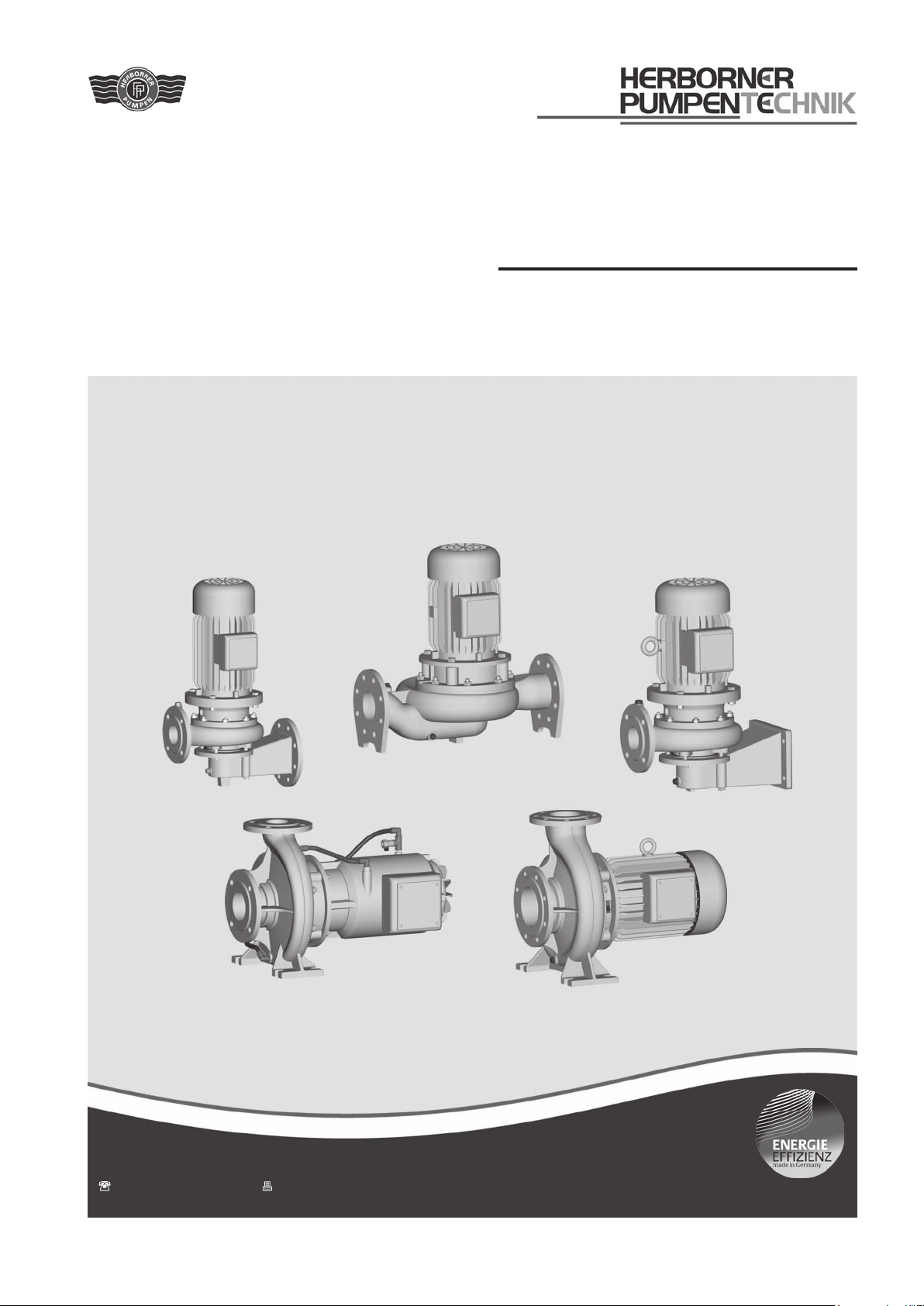
UNIBLOCK
Close coupled centrifugal pump
Operating manual Model - GF
- GFC
- GF-PM
- D
- W
- WS
Herborner Pumpentechnik GmbH & Co KG | Littau 3-5 | DE-35745 Herborn
+49 (0) 27 72 / 933-0 | +49 (0) 27 72 / 933-100
[email protected] | www.herborner-pumpen.de
Original operating manual
A - BR40 GB
Page 2

Translation
Deliveries to countries of the EEA require the operating
manual to be translated in accordance with the language
spoken in the respective country.
If any discrepancies should occur in the translated text,
reference should be made to the original operating manual
(German) for clarification or the manufacturer is to be contacted.
Copyright
The transfer and duplication of this document and utilisation
and communication of its content is prohibited, unless explicitly stated otherwise. Non-compliance with this stipulation
will result in compensation for damages.
All rights reserved.
Page 3
EC Declaration of Conformity
Herborner Pumpentechnik
GmbH & Co KG
Littau 3-5, DE-35745 Herborn
Ms J. Weygand is authorised to create the technical documentation.
Herborner Pumpentechnik
GmbH & Co KG
J. Weygand
Littau 3-5, DE-35745 Herborn
We hereby declare that the
Close coupled centrifugal pump
UNIBLOCK-GF/ -GFC/ -GF-PM/ -D/ -W/ -WS
complies with all pertinent provisions of the EC Machinery Directive 2006/42/EC.
The machine also complies with all pertinent provisions of the following EC directives:
- Directive 2004/108/EC, Appendices I and II
- Directive 94/9/EC (for explosion protection version)
Herborn, 29-12-2009 ....................................................................
Signature
(Management)
Herborner Pumpentechnik GmbH & Co KG | Littau 3-5 | DE-35745 Herborn
+49 (0) 27 72 / 933-0 | +49 (0) 27 72 / 933-100
[email protected] | www.herborner-pumpen.de
Original
Page 4

Page 5

Table of contents
Table of contents
1 General information .................................... 6
1.1 Intended use ................................................. 6
1.2 Exploded view ............................................... 8
1.3 Wear parts ...................................................10
1.4 Technical specifications............................... 10
1.4.1 Model designation ....................................... 10
1.4.2 Impellers ...................................................... 11
1.4.3 Installation ................................................... 11
1.4.4 Shaft sealing ............................................... 11
1.4.5 Drive ............................................................ 11
1.4.6 Dimensions, weight, performance data ....... 12
1.4.7 General data ............................................... 12
2 Safety ......................................................... 14
2.1 Notes / explanations.................................... 14
2.1.1 Machine identification.................................. 14
2.2 Integrated safety systems (optional) ........... 15
2.3 Connections on the pump ........................... 16
2.4 Safety measures ......................................... 16
2.5 Obligations of the operator .......................... 16
3 General hazard warnings ......................... 18
3.1 Dangers....................................................... 18
3.2 Danger zones on the pump ......................... 18
3.3 Assembly, operation and maintenance
personnel .................................................... 18
3.4 Installation of replacement parts and wear
parts ............................................................ 18
3.5 Shut off procedures ..................................... 19
4 Transport ....................................................20
4.1 Scope of delivery......................................... 20
4.2 Transport and packaging ............................20
4.2.1 Delivery (including spare parts and re-
placement parts) ........................................... 20
4.2.2 Intermediate storage ................................... 20
4.3 Transport to the site of installation
(by the customer) ........................................ 20
4.3.1 Transport with a forklift truck ....................... 20
4.3.2 Transport with a crane ................................21
5 Installation / fitting .................................... 22
5.1 Installation ................................................... 22
5.2 Dimensions ................................................. 23
5.2.1 Dimensions of GF/GF-PM model ................ 23
5.2.2 Dimensions of GFC model .......................... 28
5.2.3 Dimensions of D model ............................... 29
5.2.4 Dimensions of W model .............................. 31
5.2.5 Dimensions of WS model ............................ 33
5.3 Technical specifications............................... 35
5.4 Electrical connection ................................... 37
5.5 Motor protection .......................................... 37
5.6 Direction of rotation check........................... 38
5.6.1 Change of direction of rotation .................... 38
5.7 Motor connection diagrams ......................... 39
5.7.1 PTC thermistor connection.......................... 39
5.8 Frequency converter operation ................... 39
5.9 ETS X4 ........................................................ 40
5.10 Laying the pipes .......................................... 40
5.11 Frost protection ........................................... 40
6 Commissioning ......................................... 41
6.1 Operating modes and connecting
frequency .................................................... 41
6.2 Starting up ................................................... 42
7 Maintenance / cleaning ............................. 43
7.1 Maintenance................................................ 43
7.2 Maintenance instructions for prolonged
periods of inactivity...................................... 44
7.3 Bearing lubrication ...................................... 45
7.3.1 Relubrication unit ........................................ 45
7.3.2 Greasing intervals ....................................... 46
7.4 Seals ........................................................... 46
7.5 Cleaning ...................................................... 46
7.6 Tightening torques for nuts and bolts .......... 47
7.7 Disposal ...................................................... 47
8 Disturbance / cause / trouble shooting ... 48
9 Disassembly / assembly ........................... 50
9.1 Disassembly ................................................ 50
9.2 Assembly ..................................................... 52
Table of figures
Figure 1a Exploded view (GF/GF-PM model) ............... 8
Figure 1b Exploded view (GFC model) ......................... 8
Figure 1c Exploded view (D model) .............................. 9
Figure 1d Exploded view (W/WS model)....................... 9
Figure 2a Name plate (standard) ................................ 15
Figure 2b Name plate (explosion protection pump) .... 15
Figure 3 Connections on the pump .......................... 16
Figure 4 Transport with a crane ................................21
Figure 5a Dimensions (GF/GF-PM model) .................. 23
Figure 5b Dimensions (GFC model) ............................ 28
Figure 5c Dimensions (D model) ................................. 29
Figure 5d Dimensions (W model) ................................ 31
Figure 5e Dimensions (WS model) ............................. 33
Figure 6 Dry running label ......................................... 44
Figure 7 Relubrication label....................................... 45
5
Page 6
General information
1 General information
1.1 Intended use
The UNIBLOCK centrifugal pump is particularly suitable for
pumping clean water, cooling water, bathing water, thermal
brine, sea water, leaching solution, and oils.
It is used in indoor, outdoor, and adventure swimming baths,
water parks, waterworks, heating and air conditioning technology, ice sports, recreation and hotel facilities for water
slides, attractions, condensation plants, water treatment
systems, watering systems, washing and cleaning machines,
fountains, heat recovery systems, and industrial facilities.
Type UNIBLOCK-GF
Close coupled centrifugal pump
Type UNIBLOCK-GFC
Energy-saving, close-coupled centrifugal pump with watercooled motor (heat loss from the motor heats the pumped
medium)
Type UNIBLOCK-GF-PM
Energy-saving close-coupled circulation pump in version
with PM motor (permanent-magnet motor) with extremely
high efficiencies
Type UNIBLOCK-D
Close-coupled centrifugal inline pump
Type UNIBLOCK-W
Close-coupled centrifugal pump for tank fitment with rectangular tank connection
Type UNIBLOCK-WS
Close-coupled centrifugal pump for tank fitment with round
tank connection
Notice!
Lack of safety equipment can damage the pump.
The pumping station must conform to the respective directives and all safety equipment must be installed and fully
operational.
Only then should the pump be operated.
Danger!
Pumping flammable or explosive liquids is perilous.
Only use pumps with an explosionproof construction (Ex) in potentially
explosive atmospheres and in accordance with the corresponding specifications.
Caution!
Pumping any liquid which chemically
attacks the pump material or contains
abrasive ingredients can destroy the
pump.
Use bronze or stainless steel as the
pump material for these media.
Each pump is solely intended for the purpose previously
specified. Any other application or applications extending
beyond the stated purpose or alterations made to the pump
without prior written agreement with the manufacturer is
not permitted. The manufacturer is not liable for damages
resulting from unintended use. The responsibility is solely
that of the user.
The media used for the intended operation of the pump
and the associated dangers are the responsibility of the
operator.
6
Page 7
General information
Danger!
Air bubbles or accumulations of gas
around the mechanical seal create a
dangerous explosive atmosphere.
Provide a constant supply of pumped
media to the feed and pressure pipe as
well as the interior of the pump.
Provide appropriate monitoring measures to ensure this.
Important!
Intended use also extends to observing the operating and
maintenance conditions prescribed by the manufacturer.
The explosion-proof centrifugal pumps satisfy the requirements of electrical equipment for use in potentially explosive
atmospheres in accordance with
Directive 94/9/EC of the European Council dated 23 March
1994 for intended use in potentially explosive atmospheres
for
device group II category 2.
Operational conditions for Zone I and Zone II
Danger!
Exceeding the limit values specified
in the instructions and on the name
plate can result in a potentially fatal
explosive atmosphere.
Comply with the limit values.
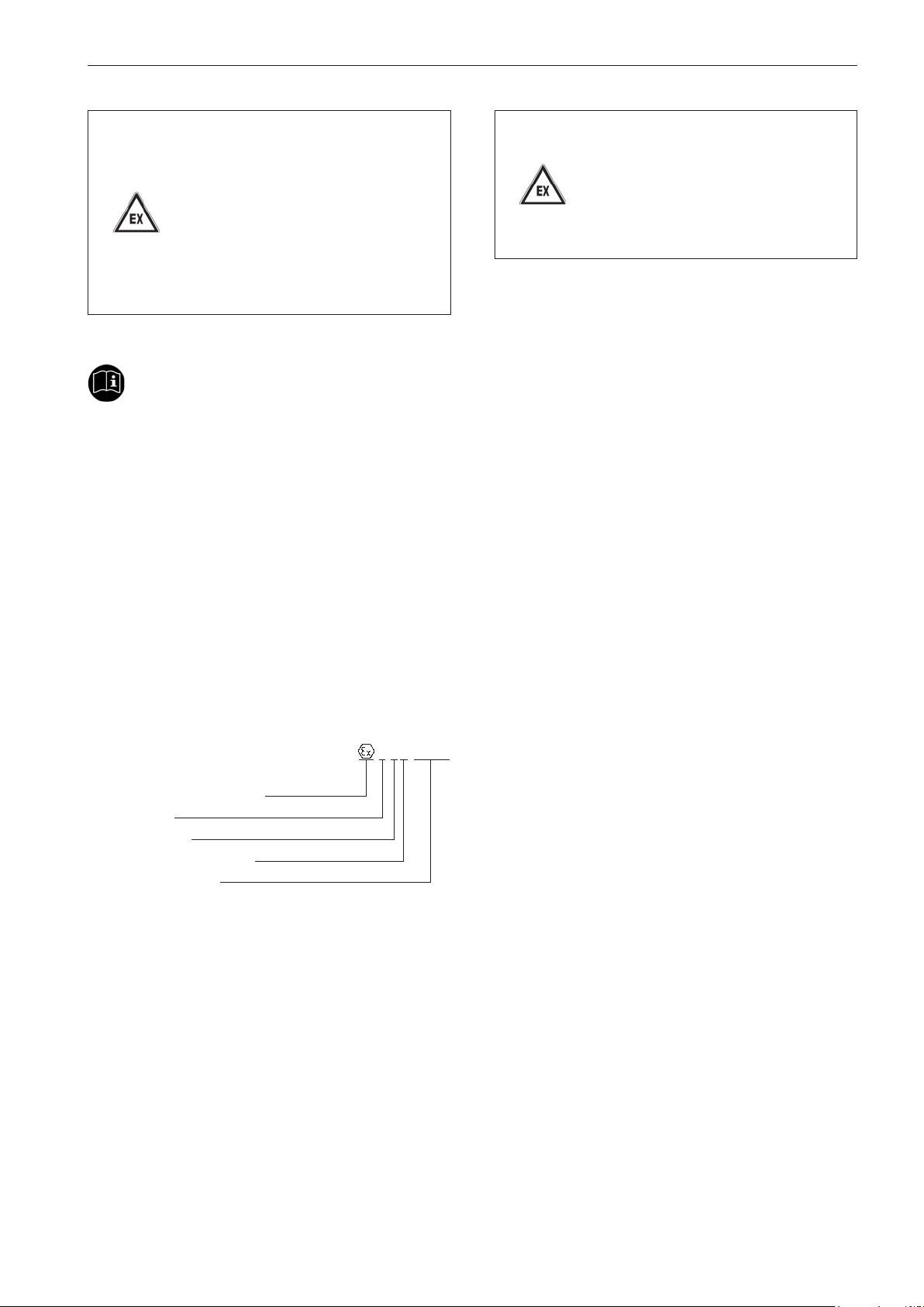
The explosion protection marking on the pump is only relevant to the pumping component. The motor has its own
explosion protection marking.
II 2G T1-T3
Explosion protection symbol
Device group
Device category
Explosive gas atmosphere
Temperature classes
The temperature class T3 means the pumps also fulfil the
requirements of temperature classes T1 to T2.
7
Page 8
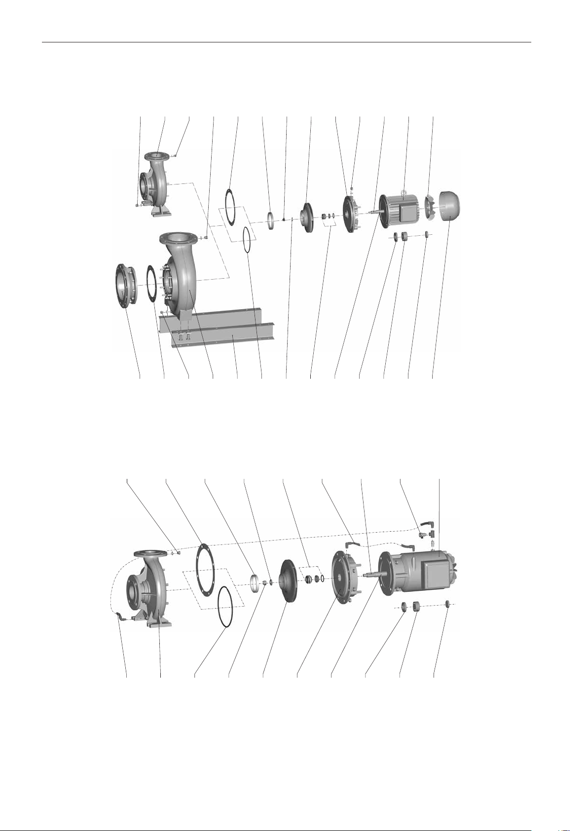
General information
1.)
1) 2)
162
400.2
903.2
101
593
554
433
819
423
320.2
320.1
412
832
1.2 Exploded view
Model GF/GF-PM
903.2
101
903.3
903.3
400.1
502
920
230
113
903.1
940
802
831
Figure 1a Exploded view (GF/GF-PM model)
Model GFC
903
704
400
101
502
412
920
554
230
433
113
702
819
940
423
006
320.2
802
320.1
Figure 1b Exploded view (GFC model)
1)
Only available in a construction with closed multi vane impeller in material version W3.
2)
In 150-401/... second casing wear ring available.
8
Page 9
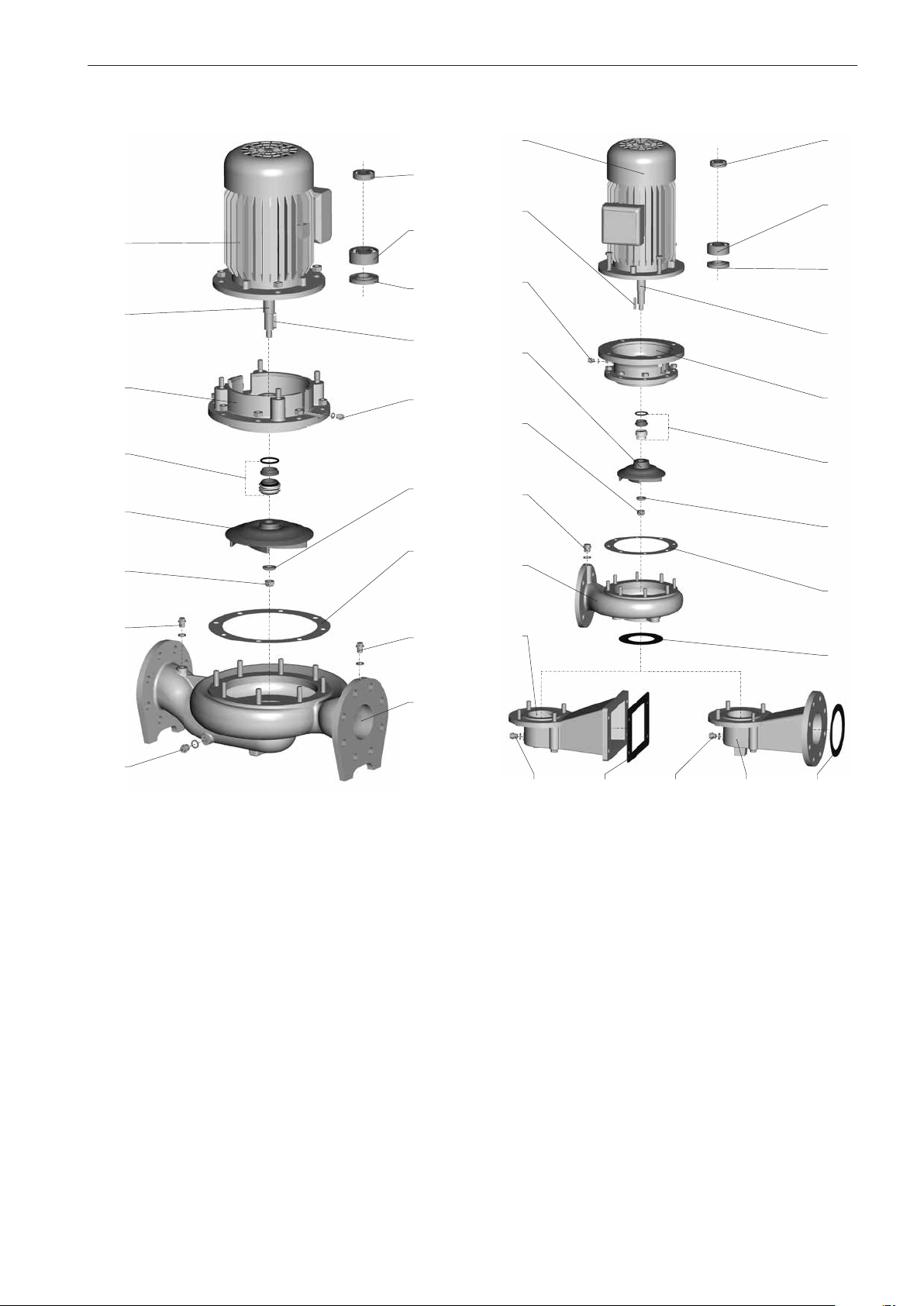
General information
Model D
802
819
113
433
230
920
320.1
320.2
423
940
903.1
554
400
Model W/WS
802
940
903.1
230
920
903.3
101
320.1
320.2
423
819
113
433
554
400.1
903.3
903.2
Figure 1c Exploded view (D model)
Individual components
006 Ball valve
101 Pump casing
113 Intermediate casing
139 Suction elbow
162 Suction cover
230 Impeller
320.1 Anti-friction bearing (non drive side)
320.2 Anti-friction bearing (drive side)
400 Gasket
400.1 Gasket
400.2 Gasket
400.3 Gasket
400.4 Gasket
412 O-ring
423 Labyrinth ring
433 Mechanical seal
903.4
101
139
400.2
400.3903.2 139 400.4903.2
Figure 1d Exploded view (W/WS model)
502 Casing wear ring
554 Washer
593 Rail
702 Return pipe
704 Cooling water pipe
802 Block motor
819 Motor shaft
831 Fan
832 Fan hood
903 Screwed plug
903.1 Screwed plug
903.2 Screwed plug
903.3 Screwed plug
903.4 Screwed plug
920 Nut
940 Key
9
Page 10
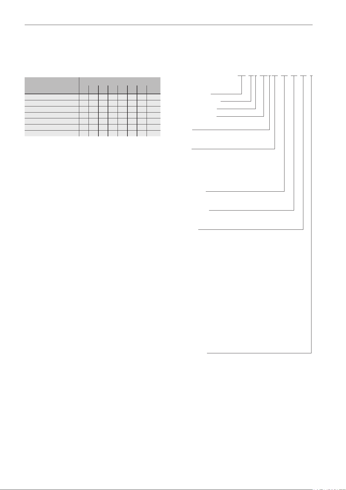
General information
1.3 Wear parts
The specifications relating to the selection of wear parts are
based on the demand for a two-year operation in accordance
with DIN 24296.
Wear parts Number of pumps
(if available) 1 2 3 4 5 6-7 8-9 10-...
Impeller 1 1 1 1 2 2 2 20%
Suction cover 1 1 1 1 2 2 2 20%
Mechanical seal set 1 1 1 2 2 2 3 25%
Anti-friction bearing set 1 1 1 2 2 2 3 25%
Labyrinth ring 1 1 1 2 2 2 3 25%
Casing wear ring 1 2 2 2 3 3 4 50%
Seal set 2 4 6 8 8 9 12 150%
1.4 Technical specifications
1.4.1 Model designation
Example:
150-270/0554GF-PM-EX-W1-S
Nominal diameter pressure
ange DN [mm]
Design dimensions
Hydraulic version
Motor rating [kW]
E.g.: 055 = 5.5 kW
Speed
2 = 3000 (60 Hz: 3600) min
4 = 1500 (60 Hz: 1800) min
Model
GF = UNIBLOCK-GF
GFC = UNIBLOCK-GFC (cooling jacket
version)
D = UNIBLOCK-D
W = UNIBLOCK-W
WS = UNIBLOCK-WS
Motor model
= standard
PM = Permanent magnet motor
Permitted use
= standard
EX = Explosion protection
Materials
W0 = mixed materials
W1 = all castings manufactured from
EN-GJL-250
W2 = all castings apart from the impeller
manufactured from EN-GJL-250,
impeller manufactured from
CuAl10Fe5Ni5-C
W3 = all castings apart from the impeller
manufactured from CuSn10-C,
impeller manufactured from
CuAl10Fe5Ni5-C
W4 = all castings manufactured from 1.4408
W5 = all castings manufactured from
EN-GJS-400-15
W6 = all castings manufactured from 1.4439
W9 = Impeller manufactured from
CuAl10Fe5Ni5-C, intermediate casing
manufactured from CuSn10-C, pump
casing manufactured from EN-GJL-250
with epoxy resin hot powder coating
Construction
= standard
S = special construction
-1
-1
10
Page 11
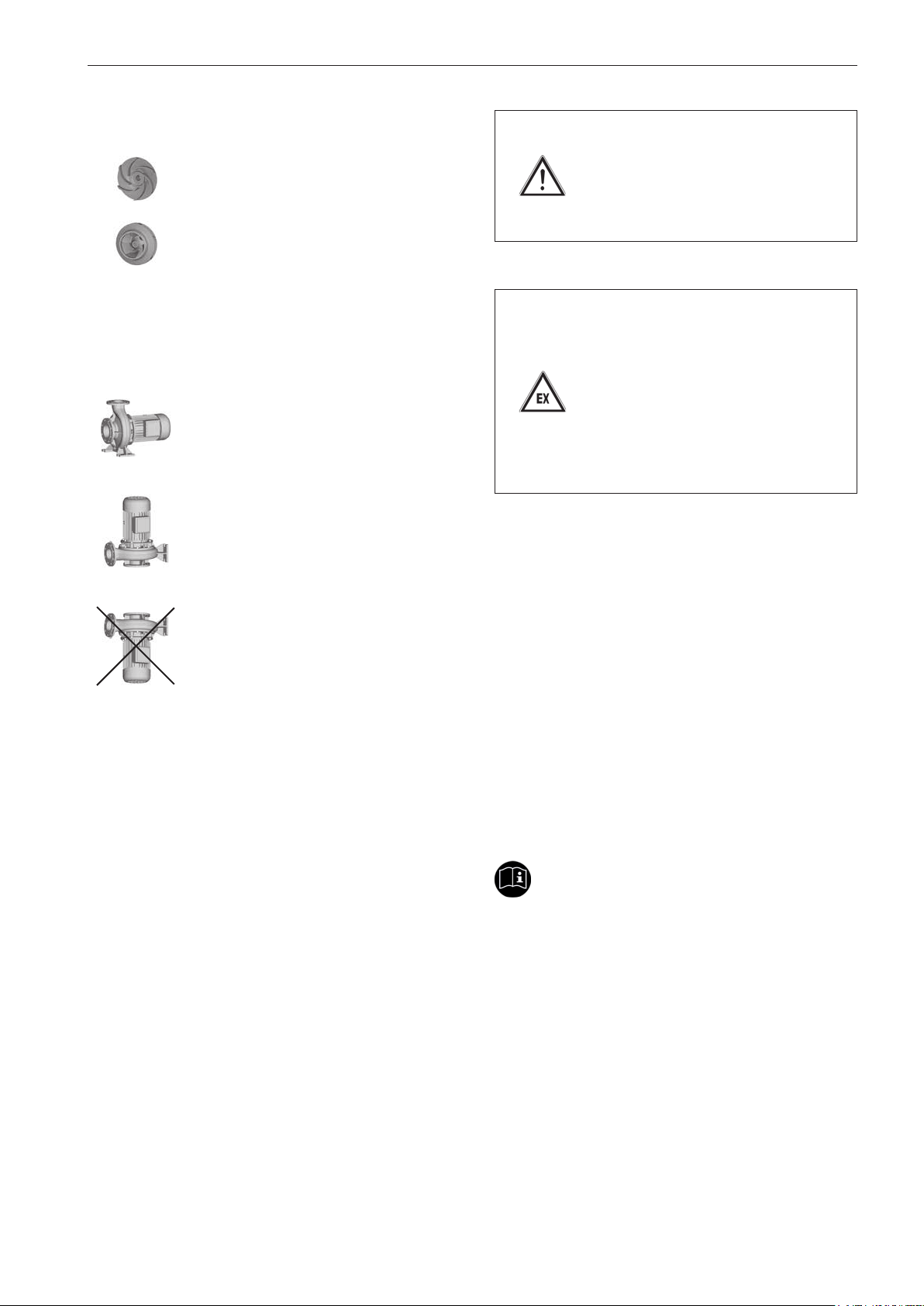
1.4.2 Impellers
Open and closed multi vane impellers for
clean to slightly soiled pumped media and
operationally safe pumping are used.
1.4.3 Installation
The pumps can be delivered in various installations:
Horizontal installation of the pump
General information
Caution!
Dry running the pump will destroy the
mechanical seal!
Ensure there is adequate cooling and
lubrication for the sliding surfaces.
Danger!
Air bubbles or accumulations of gas
around the mechanical seal create a
dangerous explosive atmosphere.
Provide a constant supply of pumped
media to the feed and pressure pipe as
well as the interior of the pump.
Provide appropriate monitoring measures to ensure this.
Vertical installation of the pump
It is not permitted to install the pump with the
"motor facing downwards" for operational
safety reasons.
1.4.4 Shaft sealing
The shaft sealing on the pump side is effected in all models
via a wear-resistant, maintenance-free mechanical seal that
is adapted to the respective operating conditions.
All motors are equipped with a special seal for splash-proofing on the pump side.
An existing ETS X4 permits monitoring of the mechanical
seal to protect it from dry running.
1.4.5 Drive
A three-phase motor with squirrel-cage drives the pump. The
motor is cooled by the dissipation of heat from the cooling
fins to the ambient air.
The motor in UNIBAD-GFC pumps is also equipped with
a jacket. The pumped medium cools this and absorbs the
motor heat.
In the case of pumps of the type UNIBAD-GF-PM, a synchronous motor with permanent excitation for operating the
frequency converter drives the pump. Observe the operating
instructions included in delivery!
Important!
Observe the limit temperatures specified in section 1.4.7
'General data'.
11
Page 12
General information
The exact motor data can be found on the name plate.
Caution!
Incorrect warming will damage the
three-phase motor.
Maintain the voltage tolerance of ± 10%
according to DIN EN 60034-1.
Motor data of models GF/GFC/D/W/WS
Design IM B5
Motor connection Manufacturer-specific
Protection type IP 55
Speed 1500 (1800) min
3000 (3600) min
-1
-1
Frequency 50 (60) Hz
Connection ≤ 2.2 kW
Connection ≥ 3.0 kW
230 5 / 400 3 (460 3) V
400 5 / 690 3 (460 5) V
Insulation class VDE 0530 F
Motor data for model X-PM GF-PM
1.4.6 Dimensions, weight, performance data
The measurements, installation dimensions and weight details can be found in section 5.2 'Dimensions'. The instruction
documents and the name plate data specify the performance
and connection data of the respective pump type.
The performance verification of the pumps is performed according to DIN EN ISO 9906 (Rotodynamic pumps - Hydraulic
performance acceptance tests), Class 2.
1.4.7 General data
Media temperature range for:
lower limit temperature: - 5 °C
upper limit temperature: + 120 °C
+ 40 °C (explosion protection
version)
Caution!
In type UNIBAD-GFC pumps, pumped
media < 15°C and > 40°C damage the
motor.
Connect another cooling circuit to the
motor.
Design IM B5
Motor connection Manufacturer-specific
Protection type IP 55
Speed 1500 min
3000 min
Connection
3 300 - 400 V
-1
-1
Insulation class VDE 0530 F
Customised solutions may differ from this standard data.
Ambient temperature range for:
lower limit temperature: - 5 °C
upper limit temperature: + 40 °C
Density and viscosity of the pumped medium:
Density: max. 1000 kg/m
3
Kinematic viscosity: max. 1 mm2/s (1 cST)
Customised solutions may differ from this standard data.
12
Page 13
General information
Power correction:
Reduce the power according to the specifications of the motor manufacturer if motors are used at ambient temperatures
> 40 °C or at altitudes > 1000 m above sea level.
A differing density or viscosity alters the hydraulic performance of the pump. Observe the motor performance with
these media.
Sound pressure level:
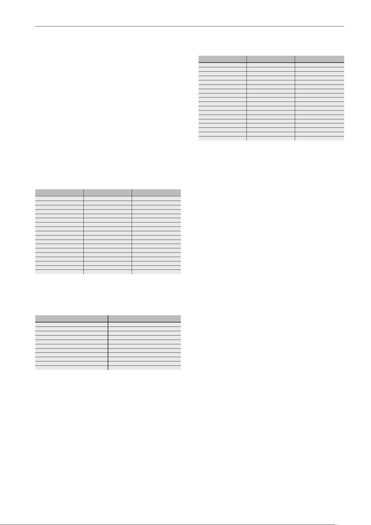
The sound pressure level dB(A) of the pump during cavitation-free operation lies within the range of Q
below the
optimal
limit values specified in EC Machinery Directive 2006/42/
EC.
Model GF/D/W/WS
50/60 Hz
P2 [kW] 1500/1800 min
0.37/0.44 52/56 61/65
0.55/0.66 50/54 61/65
0.75/0.9 50/54 63/67
1.1/1.3 55/59 63/67
1.5/1.8 55/59 67/71
2.2/2.6 59/63 67/71
3.0/3.6 59/63 72/76
4.0/4.8 59/63 74/78
5.5/6.6 63/67 74/78
7.5/9.0 63/67 74/78
11.0/13.2 65/69 75/79
15.0/18.0 65/69 75/79
18.5/22.2 65/69 75/79
22.0/26.4 67/71 75/79
30.0/36.0 68/72 -
37.0/44.4 70/74 -
45.0/54.0 70/74 -
55.0/66.0 71/75 -
-1
3000/3600 min
-1
Model GF-PM
P2 [kW] 1500 min
0.37 52 61
0.55 52 61
0.75 52 61
1.1 52 61
1.5 55 61
2.2 55 67
3.0 55 67
4.0 56 67
5.5 61 68
7.5 63 68
11.0 63 74
15.0 65 74
18.5 65 74
22.0 67 75
30.0 67 -
37.0 70 -
45.0 70 -
55.0 71 -
-1
3000 min
-1
Model GFC
50/60 Hz
P2 [kW] 1500/1800 min
1.5/1.8 49/53
2.2/2.6 49/53
3.0/3.6 49/53
4.0/4.8 49/53
5.5/6.6 49/53
7.5/9.0 49/53
11.0/13.2 50/54
15.0/18.0 50/54
18.5/22.2 52/56
22.0/26.4 52/56
30.0/36.0 52/56
-1
13
Page 14
Safety
2 Safety
2.1 Notes / explanations
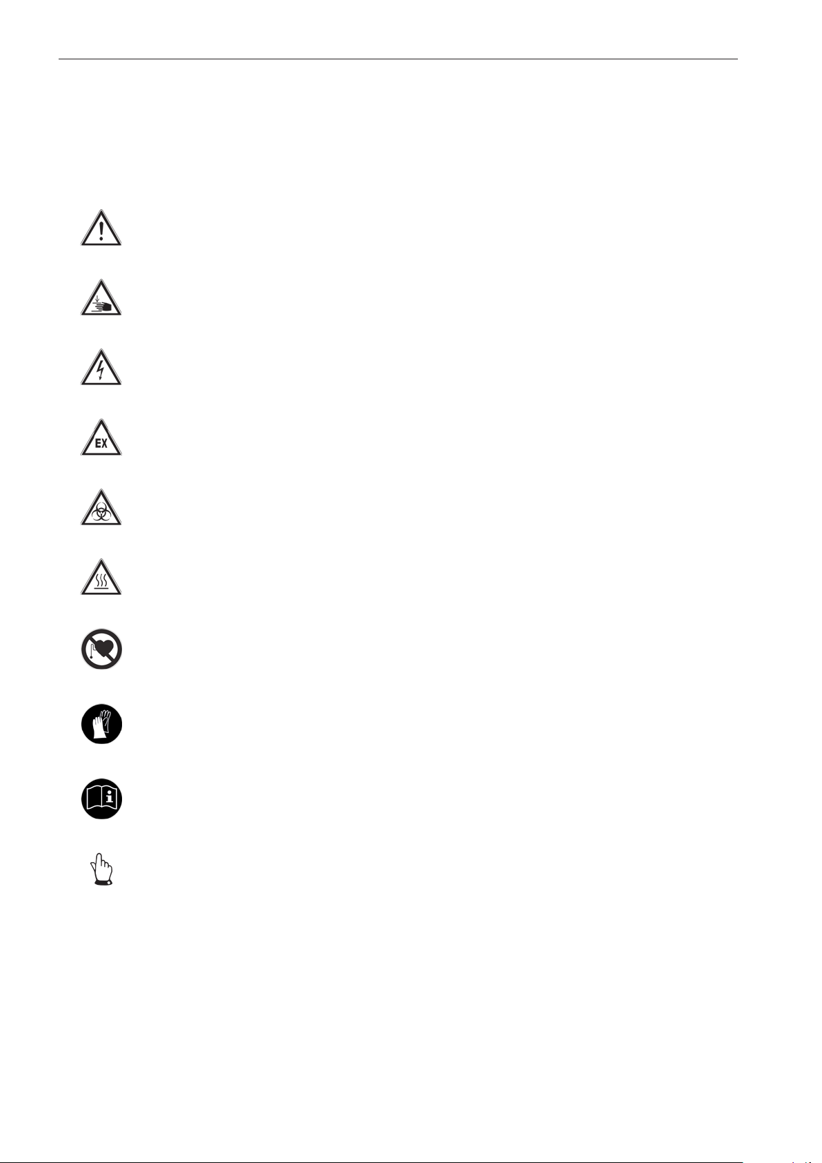
The following symbols represent
Warning of a hazardous area
Warning of hand injuries
Warning of dangerous electrical voltage
Warning of explosive atmospheres
Warning of a biohazard
The following signal words represent
This indicates an imminent danger. If it is
Danger!
Warning!
Caution!
Notice!
Important!
not avoided it will result in death or the most
severe of injuries.
This indicates a potentially dangerous situation. If it is not avoided it can result in death
or the most severe of injuries.
This indicates a potentially dangerous situation. If it is not avoided it can result in slight
or minor injuries or damage to property.
This indicates a potentially hazardous situation. If it is not avoided the product or items
in its vicinity may be damaged.
This indicates application tips and other
particularly useful information. It is not a
signal word for a dangerous or hazardous
situation.
Warning of hot surfaces
Prohibited for people with pacemakers
Command to wear protective gloves
Command to refer to the operating instructions
General information
2.1.1 Machine identification
The information contained in this operating manual is only
applicable to the pump that is indicated on the title page.
Stick the supplied name plate of the pump into the operating
manual or on the control panel. This will ensure the relevant
data is available at any time.
14
Page 15
Important!
When making any inquiries and ordering spare parts
please make sure you specify the pump type and the order
number.
Also observe the name plate on the motor.
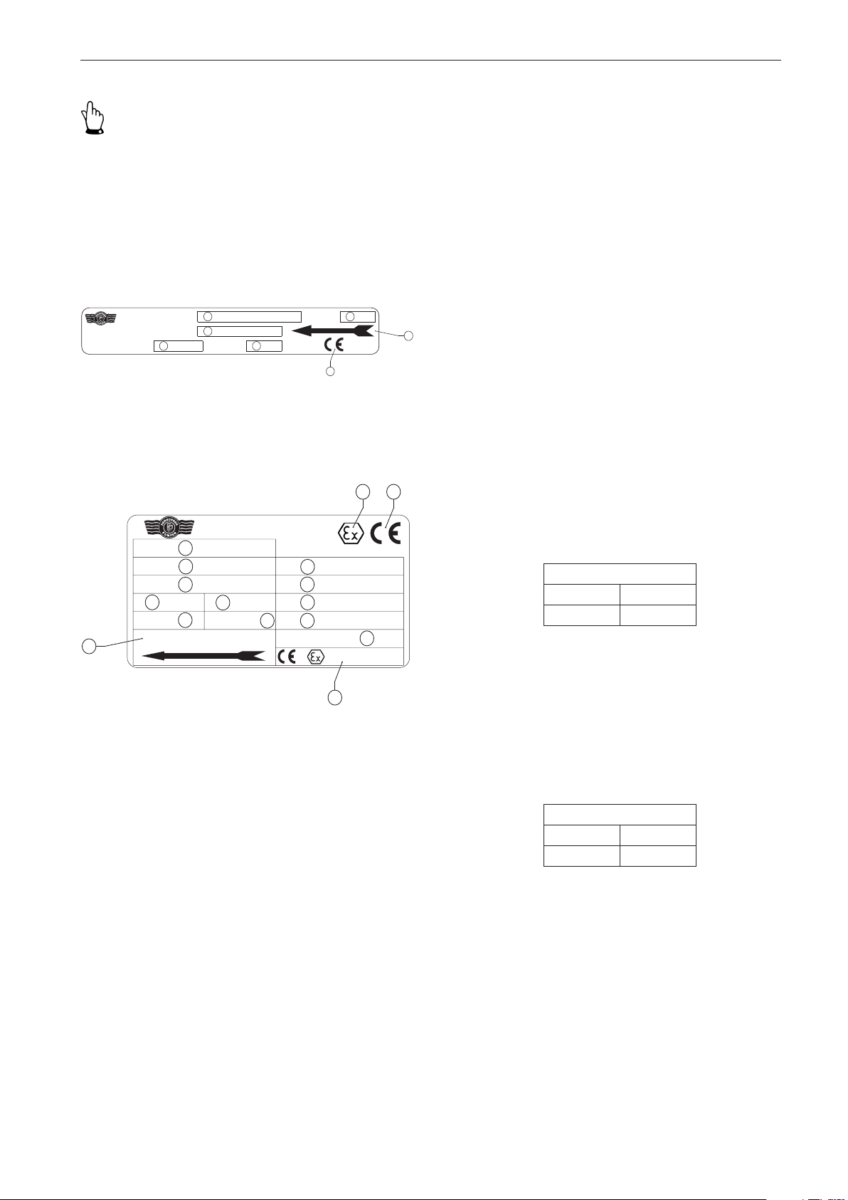
The name plate is attached to the fan hood or the motor
housing (UNIBAD-GFC).
Pumpe
Herborner Pumpenfabrik
J.H. Hoffmann GmbH&Co. KG
Littau3-5, DE-35745 Herborn
UNIBLOCK
Auftrag-Nr.
11
Q
2
1
m/h
3
10
m
Bj./ Mon.
14
16
9
Figure 2a Name plate (standard)
Safety
8. Explosion protection symbol (only for explosion protection pumps)
9. CE symbol
10. Nominal head [m]
11. Nominal flow rate [m
12. Speed (only for explosion protection pumps) [min
13. Operating voltage (only for explosion protection pumps) [V]
14. Year of manufacture/ month
15. Explosion protection marking (only for explosion protection pumps)
16. Observe the direction of rotation!
2.2 Integrated safety systems (optional)
Check the integrated safety devices in regular inspection
intervals j = annually.
The inspection methods applied here are:
S = Visual inspection, F = Functional check.
3
/h]
-1
]
Herborner Pumpenfabrik
J.H. Hoffmann GmbH&Co. KG
Littau 3-5, DE-35745 Herborn
Auftr.-Nr.:
Typ
Art.-Nr.:
16
1
2
3
4
Hz
5
6
IP 55
Isol.-Klas. F
Drehrichtung beachten!
Pumpe
H:
Q:
n:
kW
U:
7
Baujahr/Monat
10
11
12
13
II 2G T1-T3
15
Figure 2b Name plate (explosion protection pump)
Key to figure 2a and 2b
1. Order No.
2. Model designation
3. Item No. (only for explosion protection pumps)
4. Frequency (only for explosion protection
pumps)
5. Power output (only for explosion protection
pumps)
1)
6. Protection type (only for explosion protection
pumps)
7. Insulation class F (only for explosion protection pumps)
8
U/min
14
3
m/h
[kW]
9
m
V
[Hz]
Winding protection
If the pump is also equipped with thermal winding protection with direct temperature monitoring, this switches off the
pump's motor if it starts to get too hot.
Inspection
Interval Method
j S, F
ETS X4
An existing ETS X4 (electronic dry running protection system)
that uses a vibrating fork sensor prevents the dry running
of the slide ring seal. This protects the functionability of the
pump.
Inspection
Interval Method
j S, F
1)
Either power input of the pump in duty point or power output of
the motor (check by comparing with the motor name plate)
15
Page 16
Safety
Caution!
Incorrect warming will damage the
three-phase motor.
Do not decommission safety equipment
or change its mode of operation.
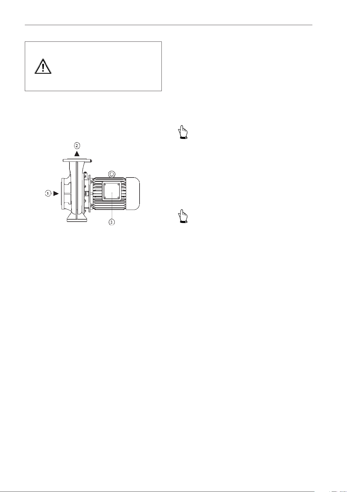
2.3 Connections on the pump
The work described in this operating manual is specified in
such a way that enables
- a trained person to understand and im-
plement instructions associated with the
section 'Commissioning',
- a specialist to understand and implement
instructions associated with the sections
'Transport', 'Installation / fitting', 'Maintenance / cleaning' and 'Disturbance / cause
/ trouble shooting'.
Important!
A trained person is understood to be a person who
- has been instructed by a specialist about the tasks they
are assigned and the possible dangers associated with
improper conduct,
- has received practical training, if necessary, and
- has been informed about the necessary protective equipment and precautions.
Figure 3 Connections on the pump
The following connections are available on the pump:
1. Inlet connecting flange
2. Outlet connecting flange
3. Electric connection (terminal box)
2.4 Safety measures
This operating manual is part of the machine and, as such,
must always be made available to operating personnel.
Please make sure that
- you observe the safety precautions it contains.
- you retain this operating manual for future use.
- you adhere to the frequency of inspections and control
measures.
Important!
According to EN 60204-1 a person is understood to be a
specialist if they
- are able to use their professional training, knowledge and
experience as well as knowledge of the relevant standards
to assess the work they have been assigned and
- are also able to identify any potential dangers.
2.5 Obligations of the operator
The operator is obligated to:
- instruct his/her operating and maintenance personnel with
regard to the pump's safety equipment and
- monitor compliance with the safety measures.
16
Page 17

Important!
In the European Economic Area observe and comply with
- the national realisation of the framework directive (89/391/
EEC) with regard to the implementation of measures for
improving the protection of health and safety of workers
at work,
- as well as the associated specific directives and the directive (89/655/EEC), in particular, concerning the minimum
requirements for the protection of health and safety of
workers when using equipment at work and
- the occupational safety regulations.
The operator has to obtain the local operating licences and
observe the associated conditions.
In addition he/she also has to comply with the local statutory
provisions for
- the safety of personnel (accident prevention regulations)
- the safety of operating equipment (protective equipment and maintenance)
- product disposal (waste management
law)
- material disposal (waste management
law)
- cleaning (cleaning agents and their disposal)
- and the relevant environmental constraints.
Safety
Connections:
Observe the local regulations (e.g. for electrical connection)
for fitting, installation and commissioning.
17
Page 18
General hazard warnings
3 General hazard warnings
3.1 Dangers
Warning!
Maintenance and repair work can
cause hand injuries.
Observe all of the safety precautions.
Observe the safety systems and safety precautions that are
described in this manual. The pump is operated by the control
elements or by the superordinate system. Keep the access
area free from any clutter while operating the pump in order
to ensure unrestricted access at all times.
3.2 Danger zones on the pump
A radius of approximately 1 m around the pump is designated
a danger zone for maintenance and cleaning work. The
control elements form the only operating area.
3.3 Assembly, operation and maintenance personnel
Assembly, operation and maintenance personnel are responsible for the transportation, fitting, installation, operation,
cleaning and reparation of the pump.
1. Only trained and authorised persons may
install and operate the pump.
2. Clearly define and observe the responsibilities for operating the pump.
3. Observe the shut off procedures specified in the operating manual for all work
processes (operation, maintenance,
repair, etc.).
4. The operator should not impair the safety
of the pump.
5. The operator has to ensure that only authorised persons work with the pump.
6. The user must notify the operator immediately of any alterations to the pump
which affect the safety measures.
7. The operator may only actuate the pump
if it is in a perfect condition.
8. The operator has to provide the operating staff with the appropriate protective
equipment according to the statutory
requirements and the pumped medium.
Caution!
Material escaping from the pump can
cause injuries.
Install or secure the pump in such
a way that the direction of pumping
is away from areas personnel may
frequent.
3.4 Installation of replacement parts and wear parts
Replacement parts and accessories that are not supplied
by the manufacturer are unchecked and, as such, are not
approved. The installation and/or use of such products may
adversely affect the specified properties of your pump.
The manufacturer accepts no responsibility whatsoever for
any damage caused by the use of non-original parts and
accessories.
18
Page 19

3.5 Shut off procedures
The following shut off procedure must be complied with
before conducting any maintenance, cleaning and/or repair
work (only by specialists).
Warning!
Electric current can result in death.
Disconnect the block motor (802) according to the 5 safety rules.
When cleaning close any electrical
cabinets that are open to prevent dust
or water from entering.
The five safety rules are as follows:
1. Disconnect.
2. Secure against reactivation.
3. De-energise.
4. Earth and short-circuit.
5. Cover or shield any adjacent live parts.
General hazard warnings
19
Page 20
Transport
4 Transport
4.1 Scope of delivery
The detailed scope of delivery can be viewed in the order
confirmation.
4.2 Transport and packaging
The pumps are carefully checked and packed before being
shipped. However, damage developing during transport
cannot be excluded.
4.2.1 Delivery (including spare parts and replacement parts)
Receiving inspection
Check the completeness of the order based on the delivery
note!
Damage
Check the delivery for signs of damage (visual inspection)!
Packaging for transportation by HGV
When the pump is transported by HGV it is packed and
secured on a transport pallet.
4.2.2 Intermediate storage
The freight packaging of the pump and the spare parts
are suitable for storage for a period of approximately 3
months.
Storage conditions
An enclosed and dry room with an ambient temperature of
5 - 40 °C.
4.3 Transport to the site of installation (by the customer)
The pump should only be transported on a transport pallet by
specialist personnel in accordance with local conditions.
Complaints
If the delivery has been damaged during transport:
- Contact the last shipping agent immediately!
- Keep the packaging (for possible review
by the shipping agent or for return shipment)
Packaging for return shipment
If possible, use the original packaging and the original
packaging material.
If neither is available:
- Contact a packaging company with specialist staff if necessary.
Place the pump on a pallet (which must
be capable of supporting the weight).
- Please contact the manufacturer if you
have any queries with regard to packaging
and transport security.
Warning!
An improperly secured pump can
cause severe injuries.
Make sure that lifting devices and stop
belts are adequate for the total weight
of the pump (see section 5.2 'Dimensions').
If necessary, secure the pump during
transport using separate lifting accessories.
Only set up the pump on a sufficiently
solid surface that is level in all directions.
4.3.1 Transport with a forklift truck
- The forklift must be designed to support
the weight of the pump.
- The driver must be authorised to operate
the forklift truck.
20
Page 21
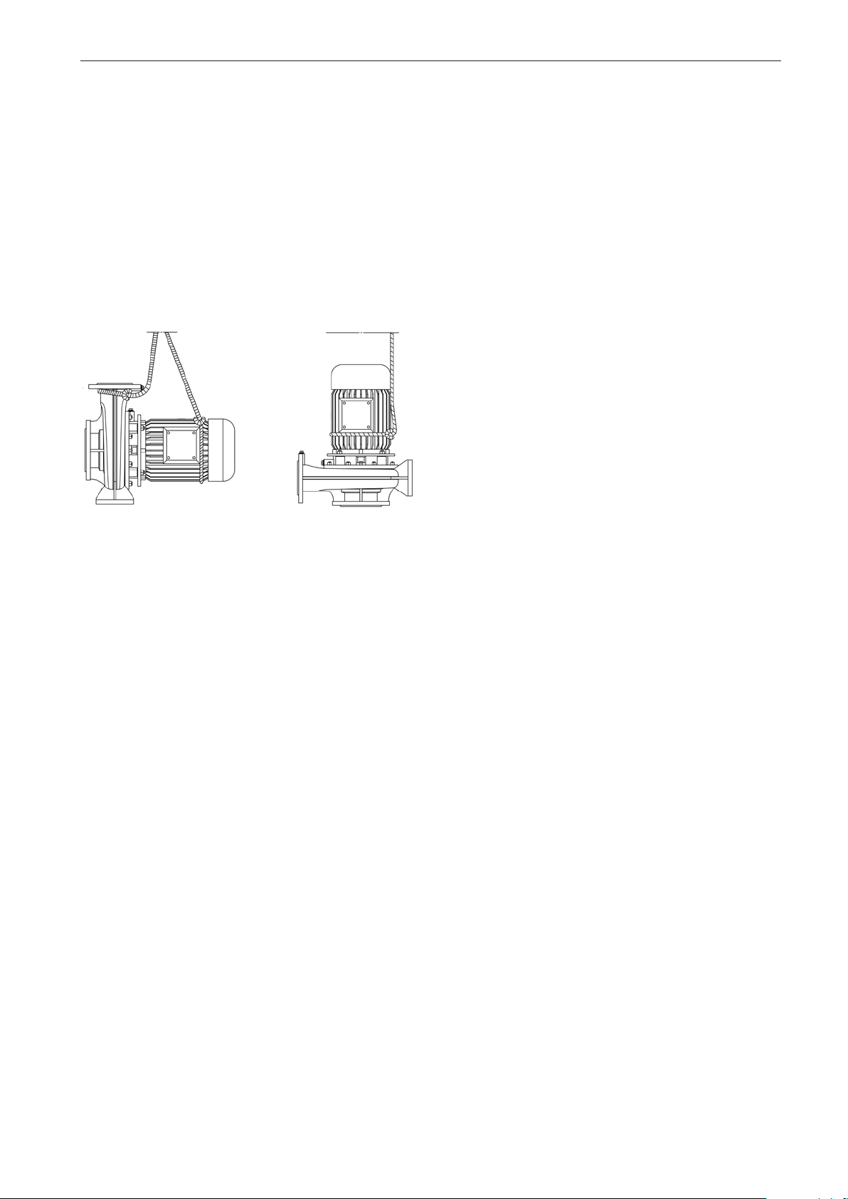
4.3.2 Transport with a crane
- The crane must be able to support the full
weight of the pump.
- The operator must be authorised to operate the crane.
- Attach the pump to the crane using the
corresponding separate lifting accessories
(e.g. cross bar, stop belt, ropes, etc.) and
the respective attachment points.
Transport
Figure 4 Transport with a crane
The measurements, installation dimensions and weight
details can be found in section 5.2 'Dimensions'.
21
Page 22
Installation / fitting
5 Installation / fitting
5.1 Installation
Prepare the construction in accordance with the pump
dimensions.
Important!
Provide sufficient room for maintenance and repair procedures!
Plan for sufficient room for opening the terminal box, for
the electrical connection, and for any existing frequency
converters.
The concrete foundation must
- have hardened,
- exhibit satisfactory rigidity (at least class
X0 according to DIN EN 206),
- have a horizontal and flat surface and
- be able to absorb vibrations, effects of
force and impacts, etc.
Only then should the pump be installed.
Caution!
Injuries may be caused when installing
the pump.
Observe the safety regulations and
the generally recognised "codes of
practice".
Caution!
A hot pump casing and hot suction
cover can burn hands and arms.
Do not touch pumps that deliver hot
water. Take precautionary measures
to prevent burning.
The connection flanges must be perfectly aligned and
screwed in such a way that prevents leakage. The seals
must be resistant to the pumped medium.
Caution!
Incorrect warming will damage the
three-phase motor.
Ensure there is an adequate supply of
cooling air during operation (except for
type UNIBAD-GFC).
In order to prevent transferring vibrations to the building
and the pipeline system it is recommended to install pipe
compensators and vibration dampers.
22
Page 23
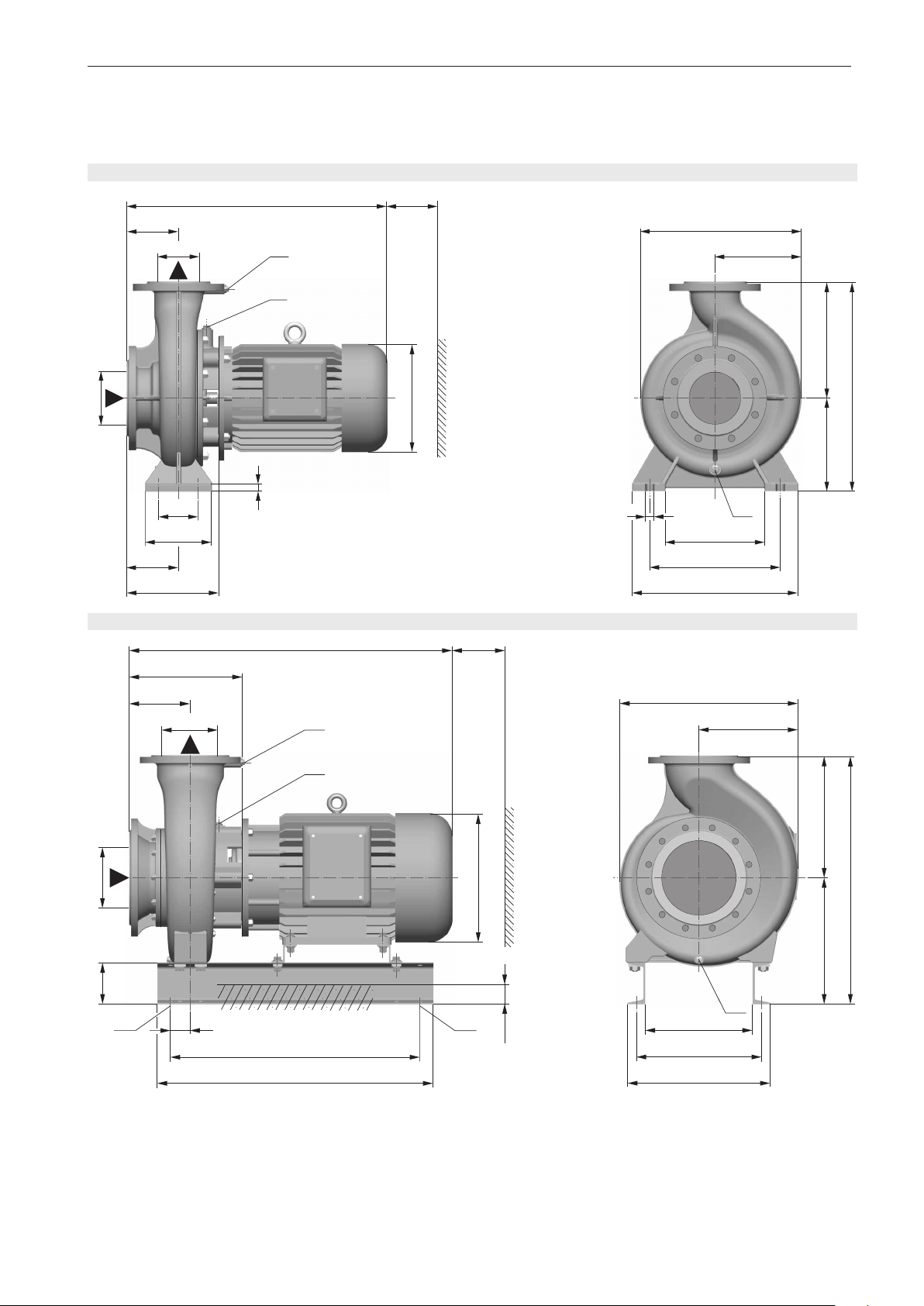
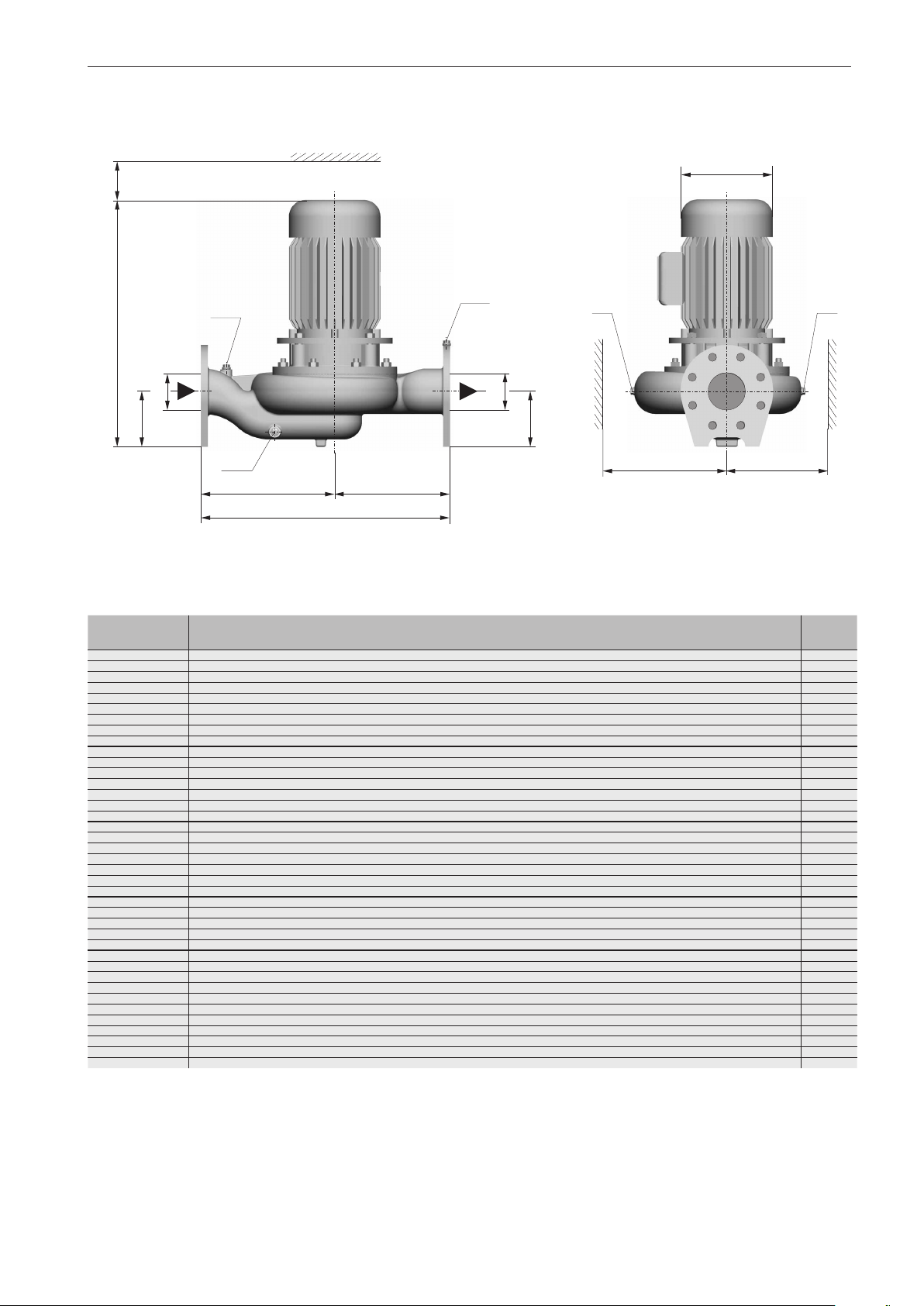
5.2 Dimensions
5.2.1 Dimensions of GF/GF-PM model
Standard
Installation / fitting
L
a
1
DN
2
G
G
1
DN
h
b
i
a
2
r
Base rail ≥ 37 kW
r
a
1
DN
2
x
g
1
4/
1
f
c
e
øk
d
q
3
G
8/
o
n
m
L
x
g
1
/
4
G
f
G
1
1
DN
b
øq
p
h
i
Figure 5a Dimensions (GF/GF-PM model)
Flange connection dimensions according to DIN 2501 PN 10
Dimensions with integrated frequency converter on request.
øq
øk
b/2
c
e
d
3
G
/
8
o
n
m
23
Page 24
Installation / fitting
Model GF
1500 (60 Hz: 1800) min
-1
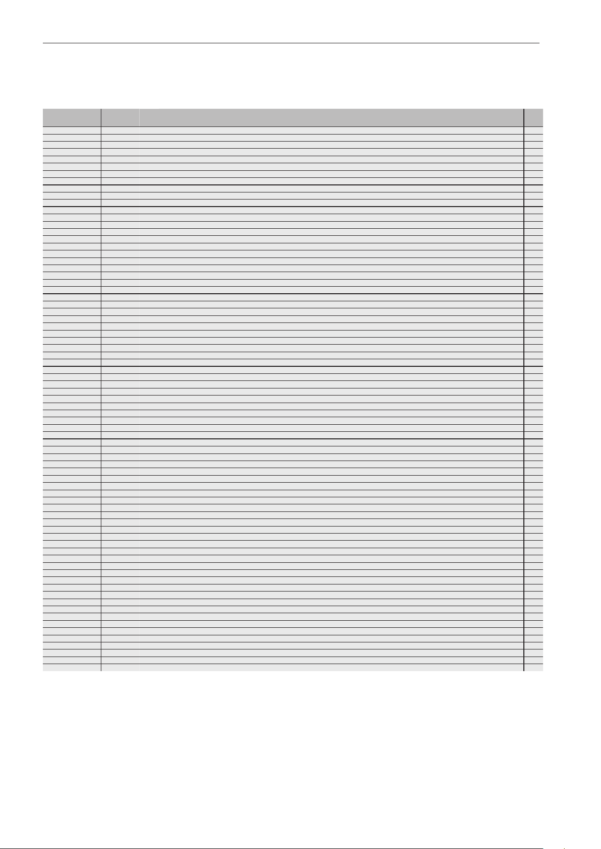
Model DN1DN2G1L a 1a 2b c d e f g h øk i o n m p q r x
25-110/0034GF 32 25
25-111/0034GF 32 25
25-112/0034GF 32 25
25-161/0034GF 32 25
25-181/0034GF 32 25
25-182/0034GF 32 25
25-183/0034GF 32 25
25-201/0054GF 32 25
32-201/0054GF 40 32
32-202/0054GF 40 32
32-201/0074GF 40 32
40-161/0034GF 50 40
40-161/0054GF 50 40
40-221/0114GF 50 40
40-221/0154GF 50 40
50-161/0034GF 65 50
50-161/0054GF 65 50
50-161/0074GF 65 50
50-191/0114GF 65 50
50-191/0154GF 65 50
50-241/0224GF 65 50
50-241/0304GF 65 50
50-241/0404GF 65 50
65-191/0114GF 80 65
65-191/0154GF 80 65
65-243/0224GF 80 65
65-243/0304GF 80 65
65-243/0404GF 80 65
65-270/0404GF 80 65
65-270/0554GF 80 65
65-301/0754GF 80 65
65-302/0754GF 80 65
65-302/1104GF 80 65
80-171/0114GF 100 80
80-171/0154GF 100 80
80-241/0224GF 100 80
80-241/0304GF 100 80
80-241/0404GF 100 80
80-242/0554GF 100 80
80-255/0754GF 100 80
80-331/1104GF 100 80
80-332/1104GF 100 80
80-332/1504GF 100 80
100-201/0224GF 125 100
100-201/0304GF 125 100
100-201/0404GF 125 100
100-270/0554GF 125 100
100-270/0754GF 125 100
100-270/1104GF 125 100
100-270/1504GF 125 100
100-333/1104GF 125 100
100-333/1504GF 125 100
100-332/1854GF 125 100
100-332/2204GF 125 100
125-250/0404GF 150 125
125-250/0554GF 150 125
125-250/0754GF 150 125
125-251/0754GF 150 125
125-250/1104GF 150
125-251/1104GF 150 125
125-251/1504GF 150 125
125-301/1504GF 150 125
125-301/1854GF 150 125
125-301/2204GF 150 125
150-270/1104GF 200 150
150-270/1504GF 200 150
150-270/1854GF 200 150
150-270/2204GF 200 150
150-331/3004GF 200 150
150-401/3704GF
150-401/4504GF
150-401/5504GF
200-350/3704GF
200-350/4504GF
200-350/5504GF
1.)
200 1503/81110 180 - 140 400 420 820 328 576 840 433 930 550 648 738 75.5 22 392 200 494
1.)
200 1503/81110 180 - 140 400 420 820 328 576 840 433 930 550 648 738 75.5 22 392 200 543
1.)
200 1503/81175 180 - 140 400 420 820 360 608 840 480 930 550 648 738 75.5 22 392 200 630
1.)
250 2003/8990 204 - 140 410 425 835 335 600 840 433 930 360 430 480 113.5 18 379 150 545
1.)
250 2003/8990 204 - 140 410 425 835 335 600 840 433 930 360 430 480 113.5 18 379 150 594
1.)
250 2003/81055 204 - 140 410 425 835 360 625 890 480 980 360 430 480 111 .0 18 379 150 702
1
/4420 100 95 15 120 11 2 232 122 204 70 138 100 90 140 190 - 14 204 150 21
1
/4420 100 95 15 120 112 232 122 204 70 138 100 90 140 190 - 14 204 150 22
1
/4420 100 95 15 120 112 232 122 204 70 138 100 90 140 190 - 14 204 150 21
1
/4420 100 100 15 150 132 282 122 229 70 138 100 140 190 240 - 14 204 150 28
1
/4415 100 100 15 150 132 282 122 239 70 138 100 140 190 240 - 14 199 150 29
1
/4415 100 100 15 150 132 282 122 239 70 138 100 140 190 240 - 14 199 150 29
1
/4415 100 100 15 150 132 282 122 239 70 138 100 140 190 240 - 14 199 150 29
1
/4445 100 100 15 180 132 312 135 262 70 156 100 140 190 240 - 14 205 150 40
1
/4445 100 100 15 180 160 340 141 268 70 156 100 140 190 240 - 14 204 150 40
1
/4445 100 100 15 180 160 340 141 268 70 156 100 140 190 240 - 14 204 150 40
1
/4445 100 100 15 180 160 340 141 268 70 156 100 140 190 240 - 14 204 150 41
1
/8425 11 0 11 0 15 160 132 292 122 229 70 138 100 140 190 240 - 14 209 150 34
1
/4450 11 0 11 0 15 160 132 292 135 242 70 156 100 140 190 240 - 14 209 150 40
1
/4480 11 0 11 0 15 200 160 360 158 295 70 176 100 165 212 265 - 14 204 150 48
1
/4505 11 0 11 0 15 200 160 360 158 295 70 176 100 165 212 265 - 14 204 150 50
1
/8430 11 5 11 5 15 180 132 312 138 251 70 138 100 140 190 240 - 14 216 150 36
1
/4460 11 5 11 5 15 180 132 312 138 251 70 156 100 140 190 240 - 14 216 150 42
1
/4460 11 5 11 5 15 180 132 312 138 251 70 156 100 140 190 240 - 14 216 150 43
3
/8490 11 5 11 5 15 200 160 360 152 279 70 176 100 165 212 265 - 14 215 150 51
3
/8515 11 5 11 5 15 200 160 360 152 279 70 176 100 165 212 265 - 14 215 150 54
3
/8515 11 5 11 5 18 220 180 400 167 317 95 198 125 190 250 320 - 14 203 150 68
3
/8555 11 5 11 5 18 220 180 400 167 317 95 198 125 190 250 320 - 14 213 150 77
3
/8590 11 5 11 5 18 220 180 400 169 319 95 220 125 190 250 320 - 14 213 150 83
3
/8500 125 125 15 210 160 370 165 303 95 176 125 150 212 280 - 14 225 150 56
3
/8525 125 125 15 210 160 370 165 303 95 176 125 150 212 280 - 14 225 150 59
3
/8520 11 5 11 5 18 230 180 410 182 338 95 198 125 190 250 320 - 14 205 150 72
3
/8560 11 5 11 5 18 230 180 410 182 338 95 198 125 190 250 320 - 14 215 150 81
3
/8595 11 5 11 5 18 230 180 410 182 338 95 220 125 190 250 320 - 14 215 150 88
3
/8575 100 100 18 225 200 425 182 347 120 220 160 200 280 360 - 18 198 150 87
3
/8630 100 100 18 225 200 425 195 360 120 260 160 200 280 360 - 18 198 150 110
3
/8670 125 125 18 270 225 495 226 427 120 260 160 240 315 400 - 18 221 150 132
3
/8670 105 105 14 270 225 495 215 411 120 260 160 240 320 400 - 18 221 150 155
3
/8730 105 105 14 270 225 495 253 449 120 315 160 240 320 400 - 18 217 150 200
1
/8505 125 125 15 220 160 380 170 302 95 176 125 150 212 280 - 14 229 150 61
1
/8530 125 125 15 220 160 380 170 302 95 176 125 150 212 280 - 14 229 150 64
3
/8530 125 125 18 250 200 450 211 379 120 198 160 200 280 360 - 18 216 150 76
3
/8565 125 125 18 250 200 450 211 379 120 198 160 200 280 360 - 18 221 150 84
3
/8600 125 125 18 250 200 450 211 379 120 220 160 200 280 360 - 18 221 150 93
3
/8680 125 125 18 250 200 450 201 366 120 260 160 200 280 360 - 18 248 150 122
3
/8695 125 125 18 270 225 495 212 386 120 260 160 240 315 400 - 18 249 150 147
3
/8745 125 125 20 280 250 530 253 474 120 315 160 240 315 400 - 18 235 150 201
3
/8760 125 125 20 315 247 562 253 467 120 315 160 240 315 400 - 18 247 150 227
3
/8795 125 125 20 315 247 562 253 467 120 315 160 240 315 400 - 18 247 150 247
3
/8570 160 160 18 280 200 480 210 369 120 198 160 200 280 360 - 18 256 150 84
3
/8605 160 160 18 280 200 480 210 369 120 198 160 200 280 360 - 18 261 150 93
3
/8640 160 160 18 280 200 480 210 369 120 220 160 200 280 360 - 18 261 150 100
3
/8650 125 125 18 280 225 505 206 384 120 260 160 240 315 400 - 18 222 150 122
3
/8670 125 125 18 280 225 505 206 384 120 260 160 240 315 400 - 18 222 150 140
3
/8745 125 125 18 280 225 505 253 431 120 315 160 240 315 400 - 18 235 150 189
3
/8785 125 125 18 280 225 505 253 431 120 315 160 240 315 400 - 18 235 150 210
3
/8745 125 125 20 290 250 540 253 458 120 315 160 240 315 400 - 18 235 150 209
3
/8785 125 125 20 290 250 540 253 458 120 315 160 240 315 400 - 18 235 150 229
3
/8880 140 140 20 370 280 650 318 561 150 350 200 300 400 500 - 24 290 150 289
3
/8915 140 140 20 370 280 650 318 561 150 350 200 300 400 500 - 24 290 150 292
3
/8620 140 140 20 355 280 635 272 467 150 220 200 300 400 500 - 24 240 200 114
3
/8670 140 140 20 355 280 635 272 467 150 260 200 300 400 500 - 24 240 200 141
3
/8690 140 140 20 355 280 635 272 467 150 260 200 300 400 500 - 24 240 200 160
3
/8735 140 170 20 355 280 635 276 483 150 260 200 300 400 500 - 24 285 200 168
1253/8765 140 140 20 355 280 635 272 467 150 315 200 300 400 500 - 24 253 200 214
3
/8810 140 170 20 355 280 635 276 483 150 315 200 300 400 500 - 24 298 200 220
3
/8845 140 170 20 355 280 635 276 483 150 315 200 300 400 500 - 24 298 200 240
3
/8795 140 140 20 355 280 635 264 474 150 315 200 300 400 500 - 24 247 200 239
3
/8905 160 160 20 400 315 715 313 559 150 350 200 300 400 500 - 24 315 200 280
3
/8940 160 160 20 400 315 715 313 559 150 350 200 300 400 500 - 24 315 200 288
3
/8815 160 160 20 400 315 715 325 574 150 315 200 350 450 550 - 24 303 200 252
3
/8850 160 160 20 400 315 715 325 574 150 315 200 350 450 550 - 24 303 200 272
3
/8920 160 160 20 400 315 715 325 574 150 350 200 350 450 550 - 24 332 200 312
3
/8960 160 160 20 400 315 715 325 574 150 350 200 350 450 550 - 24 332 200 316
3
/81015 200 200 20 400 315 715 327 587 150 400 200 350 450 550 - 24 365 200 406
min.
2.)
[kg]
1)
Base rail
2)
Total weight of the pump
24
Flange connection dimensions according to DIN 2501 PN 10
Dimensions with integrated frequency converter on request.
Page 25

Model GF
3000 (60 Hz: 3600) min
Installation / fitting
-1
Model DN1DN2G1L a 1a 2b c d e f g h øk i o n m q r x
1
25-110/0032GF 32 25
25-110/0052GF 32 25
25-110/0072GF 32 25
25-181/0112GF 32 25
25-181/0152GF 32 25
25-181/0222GF 32 25
32-131/0072GF 40 32
32-131/0112GF 40 32
32-131/0152GF 40 32
32-161/0222GF 40 32
32-191/0302GF 40 32
32-191/0402GF 40 32
32-202/0552GF 40 32
32-203/0552GF 40 32
32-201/0752GF 40 32
40-161/0222GF 50 40
40-192/0302GF 50 40
40-192/0402GF 50 40
40-193/0552GF 50 40
40-192/0752GF 50 40
40-221/0552GF 50 40 - 625 110 110 15 200 160 360 195 333 70 260 100 165 212 265 14 214 150 102
40-221/0752GF 50 40 - 660 110 110 15 200 160 360 195 333 70 260 100 165 212 265 14 214 150 104
50-161/0152GF 65 50
50-161/0222GF 65 50
50-161/0302GF 65 50
50-161/0402GF 65 50
50-181/0552GF 65 50
50-181/0752GF 65 50
50-181/1102GF 65 50
65-161/0222GF 80 65
65-161/0302GF 80 65
65-161/0402GF 80 65
65-161/0552GF 80 65
65-162/0552GF 80 65
65-161/0752GF 80 65
65-162/0752GF 80 65
65-181/0752GF 80 65
65-181/1102GF 80 65
65-181/1502GF 80 65
65-191/1102GF 80 65
65-191/1502GF 80 65
80-161/1102GF 100 80 - 750 125 125 18 225 180 405 253 410 95 315 125 190 250 320 14 237 150 165
80-161/1502GF 100 80 - 715 125 125 18 225 180 405 253 410 95 315 125 190 250 320 14 237 150 175
80-161/1852GF 100 80 - 760 125 125 18 225 180 405 253 410 95 315 125 190 250 320 14 237 150 210
80-191/1102GF 100 80
80-191/1502GF 100 80
100-192/1502GF 125 100 - 715 125 125 18 280 200 480 253 410 120 315 160 200 280 360 18 238 150 193
100-192/1852GF 125 100 - 760 125 125 18 280 200 480 253 410 120 315 160 200 280 360 18 238 150 228
100-192/2202GF 125 100 - 825 125 125 18 280 200 480 270 445 120 350 160 200 280 360 18 238 150 238
/4420 100 95 15 120 112 232 122 204 70 138 100 90 140 190 14 204 150 22
1
/4420 100 95 15 120 112 232 122 204 70 138 100 90 140 190 14 204 150 25
1
/4445 100 95 15 120 112 232 135 235 70 156 100 90 140 190 14 204 150 27
1
/4440 100 100 15 150 132 282 135 252 70 156 100 140 190 240 14 199 150 39
1
/4475 100 100 15 150 132 282 148 265 70 176 100 140 190 240 14 199 150 40
1
/4500 100 100 15 150 132 282 148 265 70 176 100 140 190 240 14 199 150 43
1
/4435 100 100 15 130 11 2 242 135 235 70 156 100 90 140 190 14 193 150 31
1
/4435 100 100 15 130 11 2 242 135 235 70 156 100 90 140 190 14 193 150 37
1
/4470 100 100 15 130 11 2 242 148 248 70 176 100 90 140 190 14 193 150 37
1
/4505 100 100 15 150 132 282 148 255 70 176 100 140 190 240 14 204 150 45
1
/4530 100 100 15 170 132 302 157 282 70 198 100 140 190 240 14 215 150 58
1
/4595 100 100 15 170 132 302 169 294 70 220 100 140 190 240 14 215 150 67
1
/4635 100 100 15 180 160 340 195 345 70 260 100 140 190 240 14 227 150 102
1
/4635 100 100 15 180 160 340 195 345 70 260 100 140 190 240 14 227 150 102
1
/4675 100 100 15 180 160 340 195 345 70 260 100 140 190 240 14 227 150 104
1
/4505 11 0 11 0 15 150 132 282 148 255 70 176 100 140 190 240 14 202 150 46
1
/4535 11 0 11 0 15 170 132 302 157 307 70 198 100 140 190 240 14 224 150 59
1
/4600 11 0 11 0 15 170 132 302 169 319 70 220 100 140 190 240 14 224 150 68
1
/4645 11 0 11 0 15 170 180 350 195 325 70 260 100 140 190 240 14 237 150 99
1
/4685 11 0 11 0 15 170 180 350 195 325 70 260 100 140 190 240 14 237 150 101
1
/4490 11 5 11 5 15 160 132 292 148 255 70 176 100 140 190 240 14 214 150 45
1
/4515 11 5 11 5 15 160 132 292 148 255 70 176 100 140 190 240 14 214 150 48
1
/4535 11 5 11 5 15 160 132 292 157 282 70 198 100 140 190 240 14 224 150 58
1
/4600 11 5 11 5 15 160 132 292 169 294 70 220 100 140 190 240 14 224 150 68
1
/4630 11 0 11 0 15 180 160 340 195 345 70 260 100 140 190 240 14 221 150 109
1
/4670 11 0 11 0 15 180 160 340 195 345 70 260 100 140 190 240 14 221 150 111
1
/4730 11 0 11 0 15 180 160 340 253 410 70 315 100 140 190 240 14 217 150 156
1
/8530 125 125 15 180 160 340 148 260 95 176 125 150 212 280 14 226 150 55
1
/4550 125 125 15 180 160 340 157 282 95 198 125 150 212 280 14 236 150 65
1
/4615 125 125 15 180 160 340 169 294 95 220 125 150 212 280 14 236 150 75
1
/4660 125 125 15 180 160 340 195 345 95 260 125 150 212 280 14 251 150 109
1
/8605 100 100 15 180 160 340 195 345 95 260 125 150 212 280 14 197 150 105
1
/4700 125 125 15 180 160 340 195 345 95 260 125 150 212 280 14 251 150 111
1
/8645 100 100 15 180 160 340 195 345 95 260 125 150 212 280 14 197 150 107
1
/4690 125 125 15 200 160 360 195 345 95 260 125 150 212 280 14 243 150 111
1
/4750 125 125 15 200 160 360 253 410 95 315 125 150 212 280 14 238 150 154
1
/4715 125 125 15 200 160 360 253 410 95 315 125 150 212 280 14 238 150 164
1
/4755 125 125 15 200 160 360 253 410 95 315 125 150 212 280 14 241 150 156
1
/4720 125 125 15 200 160 360 253 410 95 315 125 150 212 280 14 241 150 166
1
/4745 120 120 18 230 180 410 253 410 95 315 125 190 250 320 14 235 150 162
1
/4715 120 120 18 230 180 410 253 410 95 315 125 190 250 320 14 235 150 172
min.
[kg]
1)
1)
Total weight of the pump
Flange connection dimensions according to DIN 2501 PN 10
Dimensions with integrated frequency converter on request.
25
Page 26

Installation / fitting
Model GF-PM
1500 min
-1
Model DN1DN2G1L a 1a 2b c d e f g h øk i o n m p q r x
25-110/0034GF-PM 32 25
25-111/0034GF-PM 32 25
25-112/0034GF-PM 32 25
25-161/0034GF-PM 32 25
25-181/0034GF-PM 32 25
25-182/0034GF-PM 32 25
25-183/0034GF-PM 32 25
25-201/0054GF-PM 32 25
32-201/0054GF-PM 40 32
32-202/0054GF-PM 40 32
32-201/0074GF-PM 40 32
40-161/0034GF-PM 50 40
40-161/0054GF-PM 50 40
40-221/0114GF-PM 50 40
40-221/0154GF-PM 50 40
50-161/0034GF-PM 65 50
50-161/0054GF-PM 65 50
50-161/0074GF-PM 65 50
50-191/0114GF-PM 65 50
50-191/0154GF-PM 65 50
50-241/0224GF-PM 65 50
50-241/0304GF-PM 65 50
65-191/0114GF-PM 80 65
65-191/0154GF-PM 80 65
65-243/0224GF-PM 80 65
65-243/0304GF-PM 80 65
65-243/0404GF-PM 80 65
65-270/0404GF-PM 80 65
65-270/0554GF-PM 80 65
65-301/0754GF-PM 80 65
65-302/0754GF-PM 80 65
65-302/1104GF-PM 80 65
80-171/0114GF-PM 100 80
80-171/0154GF-PM 100 80
80-241/0224GF-PM 100 80
80-241/0304GF-PM 100 80
80-241/0404GF-PM 100 80
80-242/0554GF-PM 100 80
80-255/0754GF-PM 100 80
80-331/1104GF-PM 100 80
80-332/1104GF-PM 100 80
80-332/1504GF-PM 100 80
100-201/0224GF-PM 125 100
100-201/0304GF-PM 125 100
100-201/0404GF-PM 125 100
100-270/0554GF-PM 125 100
100-270/0754GF-PM 125 100
100-270/1104GF-PM 125 100
100-270/1504GF-PM 125 100
100-333/1104GF-PM 125 100
100-333/1504GF-PM 125 100
100-332/1854GF-PM 125 100
100-332/2204GF-PM 125 100
125-250/0404GF-PM 150 125
125-250/0554GF-PM 150 125
125-250/0754GF-PM 150 125
125-251/0754GF-PM 150 125
125-250/1104GF-PM 150 125
125-251/1104GF-PM 150
125-251/1504GF-PM 150 125
125-301/1504GF-PM 150 125
125-301/1854GF-PM 150 125
125-301/2204GF-PM 150 125
150-270/1104GF-PM 200 150
150-270/1504GF-PM 200 150
150-270/1854GF-PM 200 150
150-270/2204GF-PM 200 150
150-331/3004GF-PM 200 150
150-401/3704GF-PM
150-401/4504GF-PM
150-401/5504GF-PM
200-350/3704GF-PM
200-350/4504GF-PM
200-350/5504GF-PM
1)
200 1503/81050 180 - 140 400 420 820 305 553 840 392 930 550 648 738 75,5 22 392 200 433
1)
200 1503/81090 180 - 140 400 420 820 305 553 840 392 930 550 648 738 75,5 22 392 200 463
1)
200 1503/81070 180 - 140 400 420 820 364 612 840 438 930 550 648 738 75,5 22 392 200 555
1)
250 2003/8930 204 - 140 410 425 835 335 600 840 392 930 360 430 480 113,5 18 379 150 484
1)
250 2003/8970 204 - 140 410 425 835 335 600 840 392 930 360 430 480 113,5 18 379 150 514
1)
250 2003/8950 204 - 140 410 425 835 335 600 890 438 980 360 430 480 111 ,0 18 379 150 627
1
/4420 100 95 15 120 11 2 232 122 204 70 138 100 90 140 190 - 14 204 150 22
1
/4420 100 95 15 120 11 2 232 122 204 70 138 100 90 140 190 - 14 204 150 22
1
/4420 100 95 15 120 11 2 232 122 204 70 138 100 90 140 190 - 14 204 150 22
1
/4420 100 100 15 150 132 282 122 229 70 138 100 140 190 240 - 14 204 150 28
1
/4415 100 100 15 150 132 282 122 239 70 138 100 140 190 240 - 14 199 150 30
1
/4415 100 100 15 150 132 282 122 239 70 138 100 140 190 240 - 14 199 150 30
1
/4415 100 100 15 150 132 282 122 239 70 138 100 140 190 240 - 14 199 150 30
1
/4450 100 100 15 180 132 312 127 254 70 139 100 140 190 240 - 14 205 150 40
1
/4445 100 100 15 180 160 340 141 268 70 139 100 140 190 240 - 14 204 150 40
1
/4445 100 100 15 180 160 340 141 268 70 139 100 140 190 240 - 14 204 150 40
1
/4445 100 100 15 180 160 340 141 268 70 139 100 140 190 240 - 14 204 150 41
1
/8425 110 11 0 15 160 132 292 122 229 70 138 100 140 190 240 - 14 209 150 34
1
/4450 110 11 0 15 160 132 292 11 9 226 70 139 100 140 190 240 - 14 209 150 40
1
/4470 110 11 0 15 200 160 360 158 295 70 157 100 165 212 265 - 14 204 150 47
1
/4495 110 11 0 15 200 160 360 158 295 70 176 100 165 212 265 - 14 204 150 49
1
/8430 115 11 5 15 180 132 312 138 251 70 138 100 140 190 240 - 14 216 150 36
1
/4460 115 11 5 15 180 132 312 138 251 70 139 100 140 190 240 - 14 216 150 42
1
/4460 115 11 5 15 180 132 312 138 251 70 139 100 140 190 240 - 14 216 150 43
3
/8480 115 11 5 15 200 160 360 152 279 70 157 100 165 212 265 - 14 215 150 50
3
/8510 115 11 5 15 200 160 360 152 279 70 176 100 165 212 265 - 14 215 150 53
3
/8520 115 11 5 18 220 180 400 167 317 95 177 125 190 250 320 - 14 203 150 68
3
/8530 115 11 5 18 220 180 400 167 317 95 196 125 190 250 320 - 14 213 150 77
3
/8490 125 125 15 210 160 370 165 303 95 157 125 150 212 280 - 14 225 150 55
3
/8520 125 125 15 210 160 370 165 303 95 176 125 150 212 280 - 14 225 150 58
3
/8525 115 11 5 18 230 180 410 182 338 95 177 125 190 250 320 - 14 205 150 72
3
/8535 115 11 5 18 230 180 410 182 338 95 196 125 190 250 320 - 14 215 150 81
3
/8595 115 11 5 18 230 180 410 182 338 95 196 125 190 250 320 - 14 215 150 88
3
/8575 100 100 18 225 200 425 182 347 120 196 160 200 280 360 - 18 198 150 87
3
/8605 100 100 18 225 200 425 181 346 120 220 160 200 280 360 - 18 198 150 95
3
/8650 125 125 18 270 225 495 226 427 120 258 160 240 315 400 - 18 221 150 117
3
/8650 105 105 14 270 225 495 215 4 11 120 258 160 240 320 400 - 18 221 150 140
3
/8730 105 105 14 270 225 495 215 4 11 120 260 160 240 320 400 - 18 217 150 162
1
/8495 125 125 15 220 160 380 170 302 95 157 125 150 212 280 - 14 229 150 60
1
/8520 125 125 15 220 160 380 170 302 95 176 125 150 212 280 - 14 229 150 63
3
/8535 125 125 18 250 200 450 2 11 379 120 177 160 200 280 360 - 18 216 150 76
3
/8540 125 125 18 250 200 450 2 11 379 120 196 160 200 280 360 - 18 221 150 84
3
/8600 125 125 18 250 200 450 2 11 379 120 196 160 200 280 360 - 18 221 150 93
3
/8655 125 125 18 250 200 450 201 366 120 220 160 200 280 360 - 18 248 150 108
3
/8680 125 125 18 270 225 495 212 386 120 258 160 240 315 400 - 18 249 150 132
3
/8745 125 125 20 280 250 530 236 457 120 260 160 240 315 400 - 18 235 150 163
3
/8760 125 125 20 315 247 562 250 464 120 260 160 240 315 400 - 18 247 150 189
3
/8795 125 125 20 315 247 562 250 464 120 313 160 240 315 400 - 18 247 150 217
3
/8575 160 160 18 280 200 480 210 369 120 177 160 200 280 360 - 18 256 150 84
3
/8580 160 160 18 280 200 480 210 369 120 196 160 200 280 360 - 18 261 150 93
3
/8640 160 160 18 280 200 480 210 369 120 196 160 200 280 360 - 18 261 150 100
3
/8630 125 125 18 280 225 505 206 384 120 220 160 240 315 400 - 18 222 150 107
3
/8655 125 125 18 280 225 505 206 384 120 258 160 240 315 400 - 18 222 150 125
3
/8745 125 125 18 280 225 505 206 384 120 260 160 240 315 400 - 18 235 150 151
3
/8785 125 125 18 280 225 505 243 421 120 313 160 240 315 400 - 18 235 150 180
3
/8745 125 125 20 290 250 540 228 433 120 260 160 240 315 400 - 18 235 150 171
3
/8785 125 125 20 290 250 540 243 448 120 313 160 240 315 400 - 18 235 150 199
3
/8890 140 140 20 370 280 650 318 561 150 315 200 300 400 500 - 24 290 150 248
3
/8915 140 140 20 370 280 650 318 561 150 350 200 300 400 500 - 24 290 150 272
3
/8620 140 140 20 355 280 635 272 467 150 196 200 300 400 500 - 24 240 200 114
3
/8650 140 140 20 355 280 635 272 467 150 220 200 300 400 500 - 24 240 200 127
3
/8670 140 140 20 355 280 635 272 467 150 258 200 300 400 500 - 24 240 200 144
3
/8715 140 170 20 355 280 635 276 483 150 258 200 300 400 500 - 24 285 200 153
3
/8765 140 140 20 355 280 635 272 467 150 260 200 300 400 500 - 24 253 200 176
1253/8810 140 170 20 355 280 635 276 483 150 260 200 300 400 500 - 24 298 200 182
3
/8845 140 170 20 355 280 635 276 483 150 313 200 300 400 500 - 24 298 200 210
3
/8795 140 140 20 355 280 635 264 474 150 313 200 300 400 500 - 24 247 200 209
3
/8915 160 160 20 400 315 715 313 559 150 315 200 300 400 500 - 24 315 200 239
3
/8940 160 160 20 400 315 715 313 559 150 350 200 300 400 500 - 24 315 200 268
3
/8815 160 160 20 400 315 715 325 574 150 260 200 350 450 550 - 24 303 200 214
3
/8850 160 160 20 400 315 715 325 574 150 313 200 350 450 550 - 24 303 200 242
3
/8930 160 160 20 400 315 715 325 574 150 315 200 350 450 550 - 24 332 200 271
3
/8955 160 160 20 400 315 715 325 574 150 350 200 350 450 550 - 24 332 200 296
3
/81015 200 200 20 400 315 715 327 587 150 400 200 350 450 550 - 24 365 200 371
min.
2.)
[kg]
1)
Base rail
2)
Total weight of the pump
26
Flange connection dimensions according to DIN 2501 PN 10
Dimensions with integrated frequency converter on request.
Page 27

Model GF-PM
3000 min
-1
Installation / fitting
Model DN1DN2G1L a 1a 2b c d e f g h øk i o n m q r x
1
25-110/0032GF-PM 32 25
25-110/0052GF-PM 32 25
25-110/0072GF-PM 32 25
25-181/0112GF-PM 32 25
25-181/0152GF-PM 32 25
25-181/0222GF-PM 32 25
32-131/0072GF-PM 40 32
32-131/0112GF-PM 40 32
32-131/0152GF-PM 40 32
32-161/0222GF-PM 40 32
32-191/0302GF-PM 40 32
32-191/0402GF-PM 40 32
32-202/0552GF-PM 40 32
32-203/0552GF-PM 40 32
32-201/0752GF-PM 40 32
40-161/0222GF-PM 50 40
40-192/0302GF-PM 50 40
40-192/0402GF-PM 50 40
40-193/0552GF-PM 50 40
40-192/0752GF-PM 50 40
40-221/0552GF-PM 50 40 - 620 11 0 110 15 200 160 360 158 296 70 196 100 165 212 265 14 214 150 75
40-221/0752GF-PM 50 40 - 620 11 0 110 15 200 160 360 158 296 70 196 100 165 212 265 14 214 150 87
50-161/0152GF-PM 65 50
50-161/0222GF-PM 65 50
50-161/0302GF-PM 65 50
50-161/0402GF-PM 65 50
50-181/0552GF-PM 65 50
50-181/0752GF-PM 65 50
50-181/1102GF-PM 65 50
65-161/0222GF-PM 80 65
65-161/0302GF-PM 80 65
65-161/0402GF-PM 80 65
65-161/0552GF-PM 80 65
65-162/0552GF-PM 80 65
65-161/0752GF-PM 80 65
65-162/0752GF-PM 80 65
65-181/0752GF-PM 80 65
65-181/1102GF-PM 80 65
65-181/1502GF-PM 80 65
65-191/1102GF-PM 80 65
65-191/1502GF-PM 80 65
80-161/1102GF-PM 100 80 - 670 125 125 18 225 180 405 200 350 95 258 125 190 250 320 14 237 150 120
80-161/1502GF-PM 100 80 - 750 125 125 18 225 180 405 202 352 95 258 125 190 250 320 14 237 150 142
80-191/1102GF-PM 100 80
80-191/1502GF-PM 100 80
100-192/1502GF-PM 125 100 - 750 125 125
100-192/1852GF-PM 125 100 - 785 125 125 18 280 200 480 243 400 120 313 160 200 280 360 18 238 150 188
100-192/2202GF-PM 125 100 - 800 125 125 18 280 200 480 243 400 120 313 160 200 280 360 18 238 150 204
/4420 100 95 15 120 112 232 122 204 70 138 100 90 140 190 14 204 150 21
1
/4420 100 95 15 120 112 232 122 204 70 138 100 90 140 190 14 204 150 22
1
/4445 100 95 15 120 112 232 112 212 70 139 100 90 140 190 14 204 150 27
1
/4440 100 100 15 150 132 282 117 234 70 139 100 140 190 240 14 199 150 35
1
/4465 100 100 15 150 132 282 119 236 70 157 100 140 190 240 14 199 150 40
1
/4490 100 100 15 150 132 282 148 265 70 176 100 140 190 240 14 199 150 41
1
/4435 100 100 15 130 11 2 242 11 2 212 70 139 100 90 140 190 14 193 150 32
1
/4435 100 100 15 130 11 2 242 11 2 212 70 139 100 90 140 190 14 193 150 33
1
/4460 100 100 15 130 11 2 242 11 9 219 70 157 100 90 140 190 14 193 150 36
1
/4495 100 100 15 150 132 282 148 255 70 176 100 140 190 240 14 204 150 43
1
/4530 100 100 15 170 132 302 140 265 70 177 100 140 190 240 14 215 150 56
1
/4595 100 100 15 170 132 302 140 265 70 196 100 140 190 240 14 215 150 63
1
/4635 100 100 15 180 160 340 150 300 70 196 100 140 190 240 14 227 150 87
1
/4635 100 100 15 180 160 340 150 300 70 196 100 140 190 240 14 227 150 87
1
/4635 100 100 15 180 160 340 150 300 70 196 100 140 190 240 14 227 150 87
1
/4495 110 11 0 15 150 132 282 148 255 70 176 100 140 190 240 14 202 150 45
1
/4535 110 11 0 15 170 132 302 150 300 70 177 100 140 190 240 14 224 150 57
1
/4600 110 11 0 15 170 132 302 150 300 70 196 100 140 190 240 14 224 150 64
1
/4645 110 11 0 15 170 180 350 136 252 70 196 100 140 190 240 14 237 150 72
1
/4645 110 11 0 15 170 180 350 136 252 70 196 100 140 190 240 14 237 150 84
1
/4480 115 11 5 15 160 132 292 120 227 70 157 100 140 190 240 14 214 150 44
1
/4505 115 11 5 15 160 132 292 148 255 70 176 100 140 190 240 14 214 150 47
1
/4535 115 11 5 15 160 132 292 129 254 70 177 100 140 190 240 14 224 150 57
1
/4600 115 11 5 15 160 132 292 136 261 70 196 100 140 190 240 14 224 150 63
1
/4630 110 11 0 15 180 160 340 150 300 70 196 100 140 190 240 14 221 150 81
1
/4630 110 11 0 15 180 160 340 150 300 70 196 100 140 190 240 14 221 150 93
1
/4650 110 11 0 15 180 160 340 200 350 70 258 100 140 190 240 14 217 150 111
1
/8520 125 125 15 180 160 340 148 260 95 176 125 150 212 280 14 226 150 54
1
/4550 125 125 15 180 160 340 137 262 95 177 125 150 212 280 14 236 150 64
1
/4615 125 125 15 180 160 340 137 262 95 196 125 150 212 280 14 236 150 70
1
/4660 125 125 15 180 160 340 150 300 95 196 125 150 212 280 14 251 150 82
1
/8605 100 100 15 180 160 340 150 300 95 196 125 150 212 280 14 197 150 77
1
/4660 125 125 15 180 160 340 150 300 95 196 125 150 212 280 14 251 150 94
1
/8605 100 100 15 180 160 340 150 300 95 196 125 150 212 280 14 197 150 89
1
/4650 125 125 15 200 160 360 150 300 95 196 125 150 212 280 14 243 150 94
1
/4670 125 125 15 200 160 360 200 350 95 258 125 150 212 280 14 238 150 109
1
/4750 125 125 15 200 160 360 202 352 95 258 125 150 212 280 14 238 150 131
1
/4670 125 125 15 200 160 360 200 350 95 258 125 150 212 280 14 241 150 111
1
/4755 125 125 15 200 160 360 202 352 95 258 125 150 212 280 14 241 150 133
1
/4665 120 120 18 230 180 410 200 350 95 258 125 190 250 320 14 235 150 117
1
/4745 120 120 18 230 180 410 202 352 95 258 125 190 250 320 14 235 150 139
18 280 200 480 202 353 120 258 160 200 280 360 18 238 150 160
min.
[kg]
1)
1)
Total weight of the pump
Flange connection dimensions according to DIN 2501 PN 10
Dimensions with integrated frequency converter on request.
27
Page 28
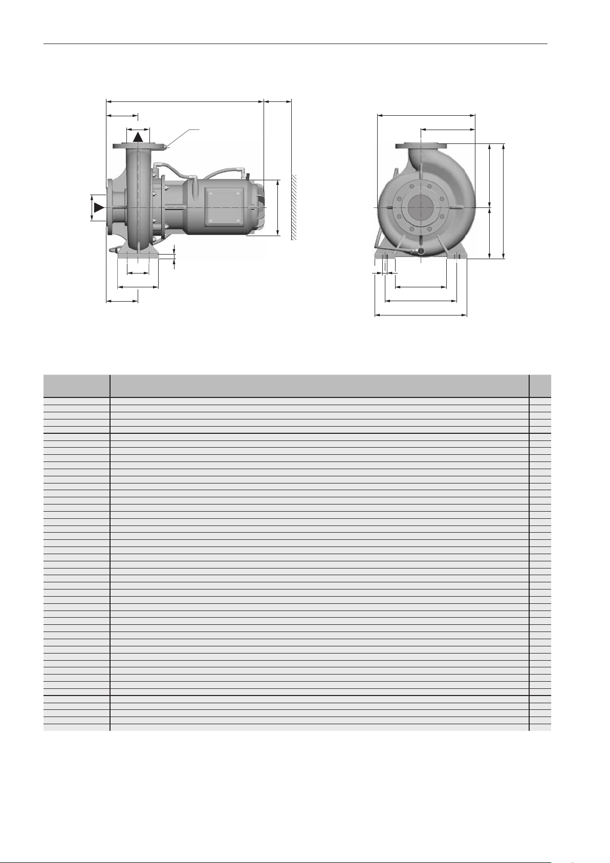
Installation / fitting
DN
5.2.2 Dimensions of GFC model
L
a
1
DN
2
1
G
/
4
x
g
f
c
1
øk
e
d
h
b
i
a
2
q
o
n
m
Figure 5b Dimensions (GFC model)
1500 (60 Hz: 1800) min
Model DN1DN2L a1a2b c d e f g h øk i o n m q x
40-221 /0154GFC 50 40 545 110 110 15 200 160 360 158 296 70 192 100 165 212 265 14 150 60
50-191 /0154GFC 65 50 555 115 115 15 200 160 360 152 279 70 192 100 165 212 265 14 150 64
50-241 /0224GFC 65 50 545 115 115 18 220 180 400 167 317 95 192 125 190 250 320 14 150 72
50-241 /0304GFC 65 50 555 115 115 18 220 180 400 167 317 95 192 125 190 250 320 14 150 69
50-241 /0404GFC 65 50 615 115 115 18 220 180 400 190 340 95 218 125 190 250 320 14 150 78
65-191 /0154GFC 80 65 565 125 125 15 210 160 370 165 303 95 192 125 150 212 280 14 150 69
65-243 /0224GFC 80 65 545 115 115 18 230 180 410 182 338 95 192 125 190 250 320 14 150 76
65-243 /0304GFC 80 65 555 115 115 18 230 180 410 182 338 95 192 125 190 250 320 14 150 73
65-243 /0404GFC 80 65 615 115 115 18 230 180 410 190 346 95 218 125 190 250 320 14 150 83
65-270 /0404GFC 80 65 600 100 100 18 225 200 425 190 352 120 218 160 200 280 360 18 150 82
65-270 /0554GFC 80 65 600 100 100 18 225 200 425 190 351 120 218 160 200 280 360 18 150 81
65-301 /0754GFC 80 65 625 125 125 18 270 225 495 206 390 120 218 160 240 315 400 18 150 88
65-302 /0754GFC 80 65 625 105 105 14 270 225 495 215 410 120 218 160 240 320 400 18 150 111
65-302 /1104GFC 80 65 680 105 105 14 270 225 495 215 410 120 258 160 240 320 400 18 150 152
80-171 /0154GFC 100 80 570 125 125 15 220 160 380 170 302 95 192 125 150 212 280 14 150 74
80-241 /0224GFC 100 80 560 125 125 18 250 200 450 211 379 120 192 160 200 280 360 18 150 80
80-241 /0304GFC 100 80 565 125 125 18 250 200 450 2 11 379 120 192 160 200 280 360 18 150
80-241 /0404GFC 100 80 625 125 125 18 250 200 450 2 11 379 120 218 160 200 280 360 18 150 87
80-242 /0554GFC 100 80 650 125 125 18 250 200 450 201 366 120 218 160 200 280 360 18 150 93
80-255 /0754GFC 100 80 650 125 125 18 270 225 495 212 386 120 218 160 240 315 400 18 150 103
80-331 /1104GFC 100 80 700 125 125 20 280 250 530 216 413 120 258 160 240 315 400 18 150 153
100-201 /0224GFC 125 100 600 160 160 18 280 200 480 210 369 120 192 160 200 280 360 18 150 88
100-201 /0304GFC 125 100 605 160 160 18 280 200 480 210 369 120 192 160 200 280 360 18 150 86
100-201 /0404GFC 125 100 665 160 160 18 280 200 480 210 369 120 218 160 200 280 360 18 150 95
100-270 /0554GFC 125 100 625 125 125 18 280 225 505 206 384 120 218 160 240 315 400 18 150 93
100-270 /0754GFC 125 100 625 125 125 18 280 225 505 206 384 120 218 160 240 315 400 18 150 96
100-270 /1104GFC 125 100 700 125 125 18 280 225 505 213 391 120 258 160 240 315 400 18 150 141
100-270 /1504GFC 125 100 700 125 125 18 280 225 505 213 391 120 258 160 240 315 400 18 150 142
100-333 /1104GFC 125 100 700 125 125 20 290 250 540 228 433 120 258 160 240 315 400 18 150 161
100-333 /1504GFC 125 100 700 125 125 20 290 250 540 228 433 120 258 160 240 315 400 18 150 161
100-332 /1854GFC 125 100 875 140 140 20 370 280 650 300 521 150 312 200 300 400 500 24 150 308
100-332 /2204GFC 125 100 875 140 140 20 370 280 650 300 521 150 312 200 300 400 500 24 150 319
125-250 /0404GFC 150 125 640 140 140 20 355 280 635 272 467 150 218 200 300 400 500 24 200 109
125-250 /0554GFC 150 125 640 140 140 20 355 280 635 272 467 150 218 200 300 400 500 24 200 11 2
125-250 /0754GFC 150 125 640 140 140 20 355 280 635 272 467 150 218 200 300 400 500 24 200 11 5
125-251 /0754GFC 150
125-250 /1104GFC 150 125 715 140 140 20 355 280 635 272 467 150 258 200 300 400 500 24 200 166
125-251 /1104GFC 150 125 760 140 170 20 355 280 635 276 483 150 258 200 300 400 500 24 200 172
125-251 /1504GFC 150 125 760 140 170 20 355 280 635 276 483 150 258 200 300 400 500 24 200 172
125-301 /1504GFC 150 125 710 140 140 20 355 280 635 264 474 150 258 200 300 400 500 24 200 171
125-301 /1854GFC 150 125 900 160 160 20 400 315 715 290 518 150 312 200 300 400 500 24 200 299
125-301 /2204GFC 150 125 900 160 160 20 400 315 715 290 518 150 312 200 300 400 500 24 200 315
150-270 /1104GFC 200 150 765 160 160 20 400 315 715 302 528 150 258 200 350 450 550 24 200 204
150-270 /1504GFC 200 150 765 160 160 20 400 315 715 302 528 150 258 200 350 450 550 24 200 204
150-270 /1854GFC 200 150 915 160 160 20 400 315 715 302 528 150 312 200 350 450 550 24 200 331
150-270 /2204GFC 200 150 915 160 160 20 400 315 715 302 528 150 312 200 350 450 550 24 200 343
150-331 /3004GFC 200 150 950 200 200 20 400 315 715 310 552 150 312 200 350 450 550 24 200 381
-1
min.
125 685 140 170 20 355 280 635 276 483 150 218 200 300 400 500 24 200 124
1)
[kg]
76
1)
Total weight of the pump
Flange connection dimensions according to DIN 2501 PN 10
28
Page 29
5.2.3 Dimensions of D model
Installation / fitting
x
1
G/
H
1
4
DN
a
1
G/
4
d e
Figure 5c Dimensions (D model)
1500 (60 Hz: 1800) min
-1
øk
1
G/
4
2
ii
DN
a
g
f
L
Model DN
25-110 /0034 D 25 390 260 65 135 125 110 110 G
25-112 /0034 D 25 390 260 65 135 125 110 110 G
25-111/0034 D 25 390 260 65 135 125 110 110 G
25-162 /0034 D 25 385 320 65 165 155 130 140 G
25-161 /0034 D 25 385 320 65 165 155 130 140 G
25-181 /0034 D 25 380 320 65 165 155 145 145 G
25-183 /0034 D 25 380 320 65 165 155 145 145 G
25-182 /0034 D 25 380 320 65 165 155 145 145 G
25-201 /0054 D 25 410 380 65 195 185 155 165 G
32-161 /0034 D 32 385 340 80 185 155 135 150 G
32-201 /0054 D 32 425 390 80 205 185 155 170 G
32-201 /0074 D 32 425 390 80 205 185 155 170 G
40-161 /0034 D 40 405 360 90 195 165 135 150 G
40-161 /0054 D 40 430 360 90 195 165 135 150 G
40-221 /0114 D 40 480 430 90 225 205 135 150 G
40-221 /0154 D 40 505 430 90 225 205 135 150 G
50-161 /0034 D 50 415 380 100 200 180 145 170 G
50-161 /0054 D 50 445 380 100 200 180 145 170 G
50-161 /0074 D 50 445 380 100 200 180 145 170 G
50-191 /0114 D 50 475 440 100 240 200 155 180 G
50-191 /0154 D 50 500 440 100 240 200 155 180 G
50-241 /0224 D 50 520 490 100 270 220 175 195 G
50-241 /0304 D 50 560
65-191 /0114 D 65 480 465 105 255 210 165 190 G
65-191 /0154 D 65 505 465 105 255 210 165 190 G
65-201 /0224 D 65 515 465 105 255 210 165 190 G
65-241 /0304 D 65 565 500 105 270 230 185 210 G
65-241 /0404 D 65 600 500 105 270 230 185 210 G
80-171 /0114 D 80 500 480 120 260 220 160 195 G
80-171 /0154 D 80 525 480 120 260 220 160 195 G
80-211 /0224 D 80 575 540 120 290 250 185 225 G
80-211 /0304 D 80 610 540 120 290 250 185 225 G
80-241 /0404 D 80 620 575 120 330 245 190 230 G
80-241 /0554 D 80 675 575 120 330 245 190 230 G
80-255 /0554 D 80 675 605 120 335 270 200 240 G
80-255 /0754 D 80 690 605 120 335 270 200 240 G
80-255 /1104 D 80 780 605 120 335 270 200 240 G
100-211 /0224 D 100 570 580 130 320 260 180 240 G
100-211 /0304 D 100 605 580 130 320 260 180 240 G
1/2
H L a d e f
490 100 270 220 175 195 G3/
min.
g
min.
.
.
3)
i
1
/
1
/
1
/
1
/
1
/
1
/
1
/
1
/
1
/
1
/
1
/
1
/
3
/
3
/
3
/
3
/
3
/
3
/
3
/
3
/
3
/
3
/
3
/
3
/
3
/
3
/
3
/
3
/
3
/
3
/
3
/
3
/
3
/
3
/
3
/
3
/
3
/
3
/
øk x
138 150 22
4
138 150 22
4
138 150 22
4
138 150 28
4
138 150 28
4
138 150 29
4
138 150 29
4
138 150 29
4
156 150 40
4
138 150 30
4
156 150 40
4
156 150 41
4
138 150 33
8
156 150 39
8
176 150 46
8
176 150 49
8
138 150 37
8
156 150 43
8
156 150 44
8
176 150 52
8
176 150 55
8
198 150 65
8
198 150 72
8
176 150 56
8
176 150 59
8
198 150 68
8
198 150 77
8
220 150 84
8
176 150 59
8
176 150 62
8
198 150 76
8
198 150 83
8
220 150 91
8
260 150 123
8
260 150 126
8
260 150 146
8
315
8
198 150 76
8
198 150 84
8
min.
2)
1)
.
[kg]
192
1)
Total weight of the pump
2)
When dismounting the motor ensure there is sufficient room for
the lifting device.
3)
The pressure or suction flange and motor will be drilled only
when horizontal.
Flange connection dimensions according to DIN 2501 PN 10
29
Page 30
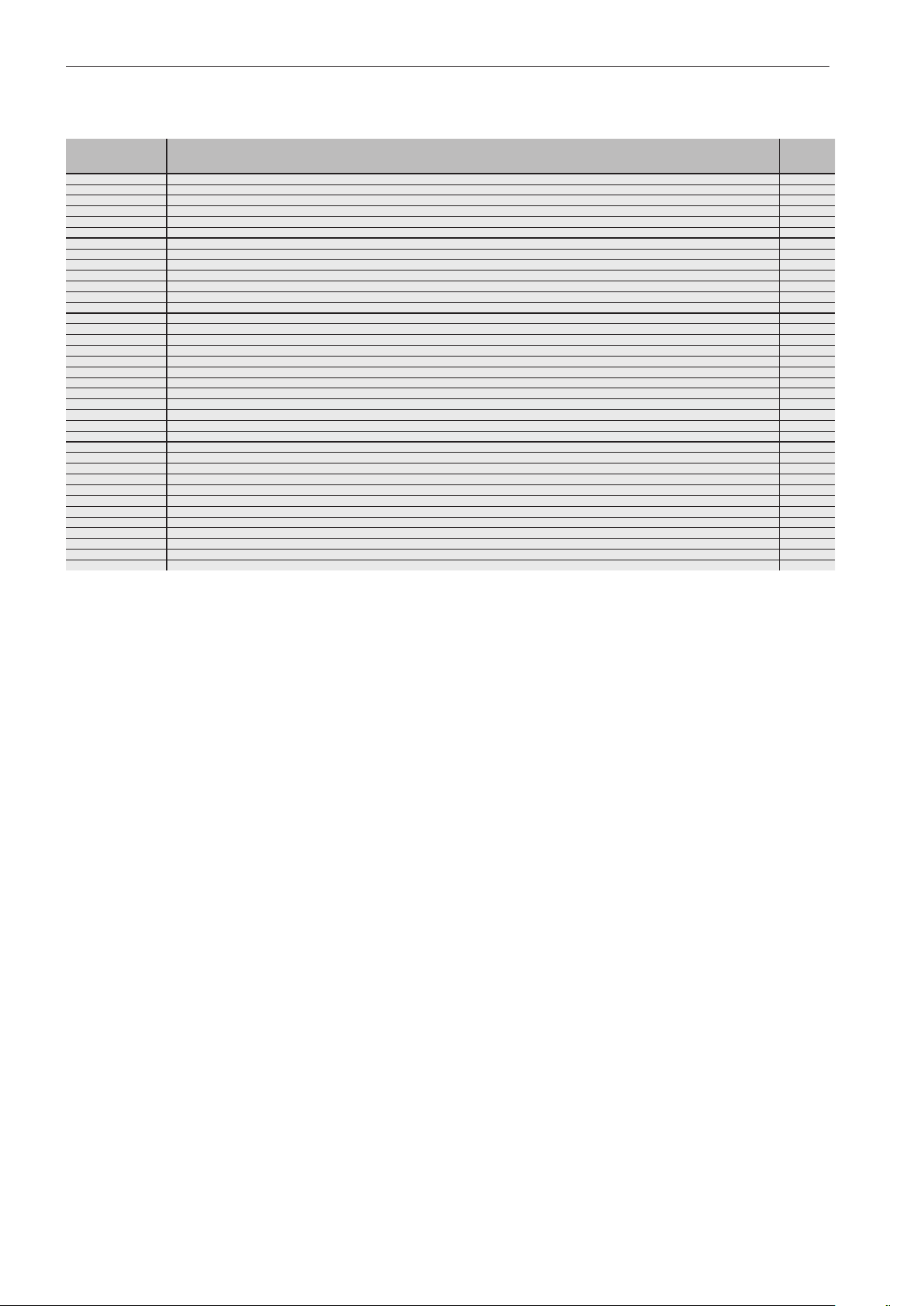
Installation / fitting
3000 (60 Hz: 3600) min
Model DN
25-110 /0032 D 25 385 260 65 135 125 11 0 11 0 - 138 150 22
25-110 /0052 D 25 385 260 65 135 125 11 0 11 0 G
25-110 /0072 D 25 410 260 65 135 125 11 0 11 0 G
25-181 /0112 D 25 405 320 65 165 155 145 145 G
25-181 /0152 D 25 440 320 65 165 155 145 145 G
25-181 /0222 D 25 465 320 65 165 155 145 145 G
32-131 /0072 D 32 370 300 75 165 135 120 130 G
32-131 /0112 D 32 370 300 75 165 135 120 130 G
32-131 /0152 D 32 405 300 75 165 135 120 130 G
32-161 /0222 D 32 485 330 80 175 155 135 145 G
32-191 /0302 D 32 510 370 80 195 175 150 160 G
32-191 /0402 D 32 575 370 80 195 175 150 160 G
32-201 /0552 D 32 615 390 80 205 185 155 170 G
40-161 /0112 D 40 425 340 90 185 155 135 150 G
40-161 /0152 D 40 460 340 90 185 155 135 150 G
40-161 /0222 D 40 485 340 90 185 155 135 150 G
40-162 /0302 D 40 505 340 90 185 155 135 150 G
40-161 /0302 D 40 505 340 90 185 155 135 150 G
40-191 /0402 D 40 580 370 85 195 175 150 165 G
40-193 /0552 D 40 620 360 85 190 170 150 165 G
40-192 /0552 D 40 620 360 85 190 170 150 165 G
50-161 /0152 D 50 475 360 100 195 165 135 150 G
50-161 /0222 D 50 500 360 100 195
50-161 /0302 D 50 520 360 100 195 165 135 150 G
50-161 /0402 D 50 585 360 100 195 165 135 150 G
65-161 /0222 D 65 510 390 105 205 185 145 170 G
65-161 /0302 D 65 530 390 105 205 185 145 170 G
65-161 /0402 D 65 595 390 105 205 185 145 170 G
65-161 /0552 D 65 640 390 105 205 185 145 170 G
65-161 /0752 D 65 680 390 105 205 185 145 170 G
65-191 /0752 D 65 670 455 105 255 200 160 185 G
65-192 /1102 D 65 735 455 105 255 200 160 185 G
65-191 /1102 D 65 735 455 105 255 200 160 185 G
65-192 /1502 D 65 700 455 105 255 200 160 185 G
65-191 /1502 D 65 700 455 105 255 200 160 185 G
80-191 /1102 D 80 745 510 120 275 235 170 210 G
80-191 /1502 D 80 715 510 120 275 235 170 210 G
-1
1/2
H L a d e f
min.
g
min.
.
165 135 150 G3/
3)
i
.
1
/
1
/
1
/
1
/
1
/
1
/
1
/
1
/
1
/
1
/
1
/
1
/
1
/
1
/
1
/
1
/
1
/
1
/
1
/
1
/
3
/
3
/
3
/
3
/
3
/
3
/
3
/
3
/
3
/
3
/
3
/
3
/
3
/
3
/
3
/
øk x
138 150 25
4
156 150 27
4
156 150 39
4
176 150 39
4
176 150 42
4
156 150 30
4
156 150 36
4
176 150 36
4
176 150 43
4
198 150 57
4
220 150 67
4
260 150 103
4
156 150 41
4
176 150 42
4
176 150 44
4
198 150 55
4
198 150 55
4
220 150 67
4
260 150 98
4
260 150 98
4
176 150 46
8
176 150 51
8
198 150 59
8
220 150 68
8
176 150 54
8
198 150 64
8
220 150 74
8
260 150 108
8
260 150 110
8
260 150 111
8
315
8
315
8
315
8
315
8
315
8
315
8
min.
2)
2)
2)
2)
2)
2)
.
1)
[kg]
155
155
166
166
159
169
1)
Total weight of the pump
2)
When dismounting the motor ensure there is sufficient room for
the lifting device.
30
3)
The pressure or suction flange and motor will be drilled only
when horizontal.
Flange connection dimensions according to DIN 2501 PN 10
Page 31
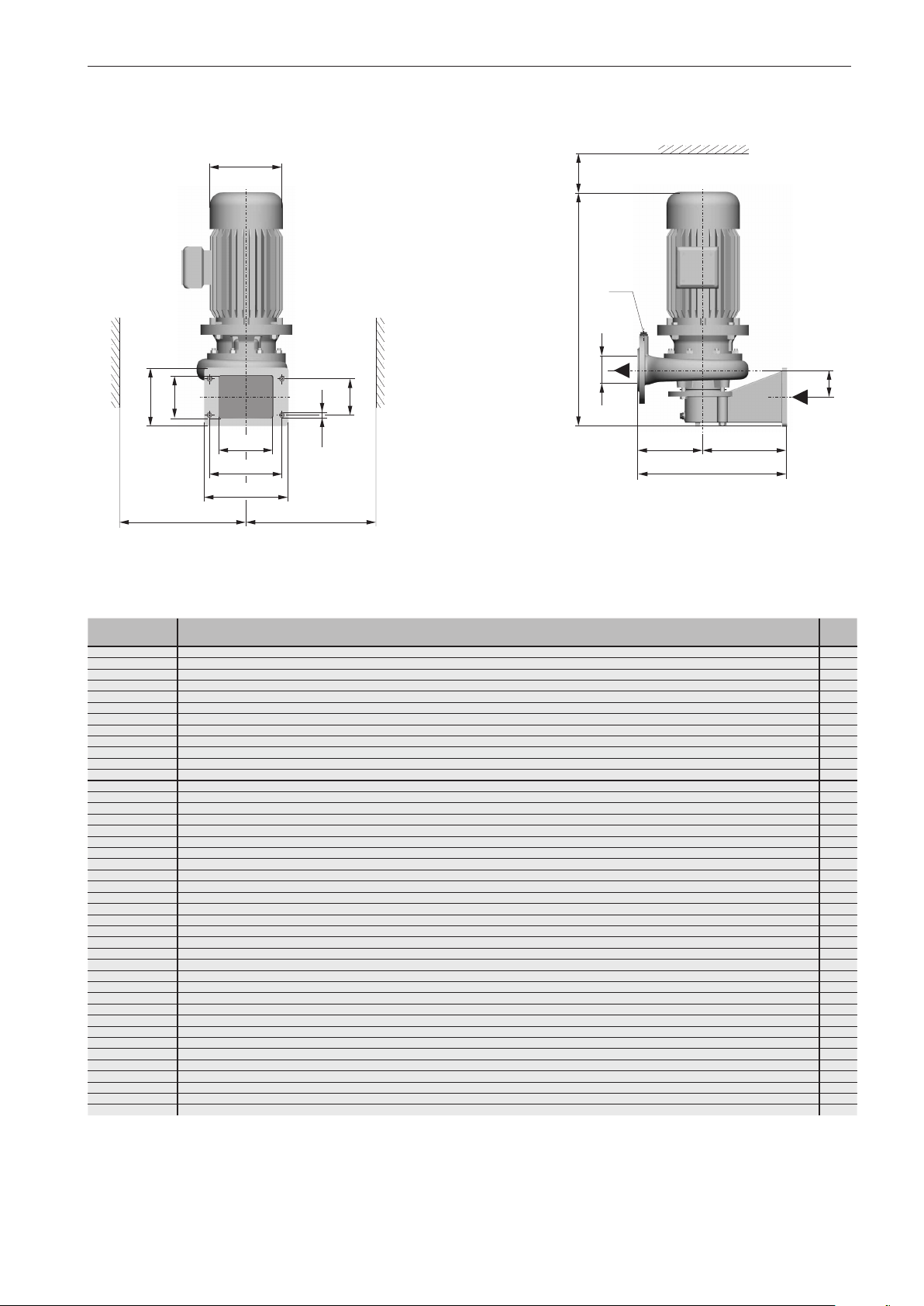
5.2.4 Dimensions of W model
Installation / fitting
øk
s
n
r
p
m
g
Figure 5d Dimensions (W model)
1500 (60 Hz: 1800) min
-1
x
1
G/
4
H
2
DN
a
q
ø14
e
d
L
f
Model DN2G
25-110/0034W 25
25-112/0034W 25
25-111/0034W 25
25-162/0034W 25
25-161/0034W 25
25-181/0034W 25
25-183/0034W 25
25-182/0034W 25
25-201/0054W 25
32-161/0034W 32
32-201/0054W 32
32-201/0074W 32
40-161/0034W 40
40-161/0054W 40
40-221/0114W 40
40-221/0154W 40
50-161/0034W 50
50-161/0054W 50
50-161/0074W 50
50-191/0114W 50
50-191/0154W 50
50-241/0224W 50
50-241/0304W 50
65-191/0114W 65
65-191/0154W 65
65-201/0224W 65
65-241/0304W 65
65-241/0404W 65
80-171/0114W 80
80-171/0154W 80
80-211/0224W 80
80-211/0304W 80
80-241/0404W 80
80-241/0554W 80
80-255/0554W 80
80-255/0754W
80-256/1104W 80
80-255/1104W 80
100-211/0224W 100 - 640 520 138 250 270 180 240 198 230 160 200 100 148 11 8 150 95
100-211/0304W 100
125-252/0404W 125
125-252/0554W 125
80 3/8775 520 101 250 270 200 240 260 230 160 200 100 148 11 8 150 152
H L a d e f
1
1
/4445 300 56 180 120 100 11 0 138 210 145 175 90 100 80 150 26
1
/4445 300 56 180 120 100 11 0 138 210 145 175 90 100 80 150 26
1
/4445 300 56 180 120 100 11 0 138 210 145 175 90 100 80 150 26
1
/4445 330 54 180 150 125 140 138 210 145 175 90 100 80 150 31
1
/4445 330 54 180 150 125 140 138 210 145 175 90 100 80 150 31
1
/4440 330 55 180 150 135 140 138 210 145 175 90 100 80 150 31
1
/4440 330 55 180 150 135 140 138 210 145 175 90 100 80 150 32
1
/4440 330 55 180 150 135 140 138 210 145 175 90 100 80 150 32
1
/4480 360 62 180 180 150 165 156 210 145 175 90 100 80 150 43
1
/4435 330 56 180 150 130 145 138 210 145 175 90 100 80 150 33
1
/4480 360 63 180 180 150 170 156 210 145 175 90 100 80 150 44
1
/4480 360 63 180 180 150 170 156 210 145 175 90 100 80 150 45
1
/4450 360 63 200 160 130 155 138 210 145 175 90 125 102 150 37
1
/4475 360 63 200 160 130 155 156 210 145 175 90 125 102 150 44
1
/4535 400 74 200 200 165 185 176 210 145 175 90 125 102 150 56
1
/4560 400 74 200 200 165 185 176 210 145 175 90 125 102 150 59
1
/4460 380 71 200 180 140 175 138 210 145 175 90 125 102 150 43
1
/4485 380 71 200 180 140 175 156 210 145 175 90 125 102 150 50
1
/4485 380 71 200 180 140 175 156 210 145 175 90 125 102 150 51
3
/8520 400 71 200 200 155 175 176 210 145 175 90 125 102 150 55
3
/8545 400 71 200 200 155 175 176 210 145 175 90 125 102 150 58
1
/4565 420 76 200 220 175 195 198 210 145 175 90 125 102 150 73
3
/8610 420 76 200 220 175 195 198 210 145 175 90 125 102 150 79
3
/8540 440 82 230 210 165 190 176 230 160 200 100 148 11 8 150 66
3
/8565 440 82 230 210 165 190 176 230 160 200 100 148 11 8 150 69
1
/4575 440 82 230 210 165 190 198 230 160 200 100 148 11 8 150 73
3
/8625 460 84 230 230 185 210 198 230 160 200 100 148 11 8 150 85
3
/8660 460 84 230 230 185 210 220 230 160 200 100 148 11 8 150 92
1
/4595 470 115 250 220 160 195 176 230 160 200 100 148 118 150 69
1
/4620 470 115 250 220 160 195 176 230 160 200 100 148 118 150 72
1
/4615 480 119 230 250 190 230 198 230 160 200 100 148 118 150 93
1
/4650 480 119 230 250 190 230 198 230 160 200 100 148 118 150 100
3
/8710 500 109 250 250 190 230 220 230 160 200 100 148 11 8 150 98
3
/8760 500 109 250 250 190 230 260 230 160 200 100 148 11 8 150 130
3
/8755 520 101 250 270 200 240 260 230 160 200 100 148 11 8 150 133
1
/4865 520 101 250 270 200 240 315 230 160 200 100 148 11 8
1
/4865 520 101 250 270 200 240 315 230 160 200 100 148 11 8
3
/8680 520 138 250 270 180 240 198 230 160 200 100 148 11 8 150 103
3
/8735 550 158 250 300 205 270 220 230 160 200 100 148 11 8 200 131
3
/8785 550 158 250 300 205 270 260 230 160 200 100 148 11 8 200 158
min.g min.
øk m n p q r s x
min.
2)
2)
[kg]
201
201
1)
1)
Total weight of the pump
2)
When dismounting the motor ensure there is sufficient room for
the lifting device.
Flange connection dimensions according to DIN 2501 PN 10
31
Page 32
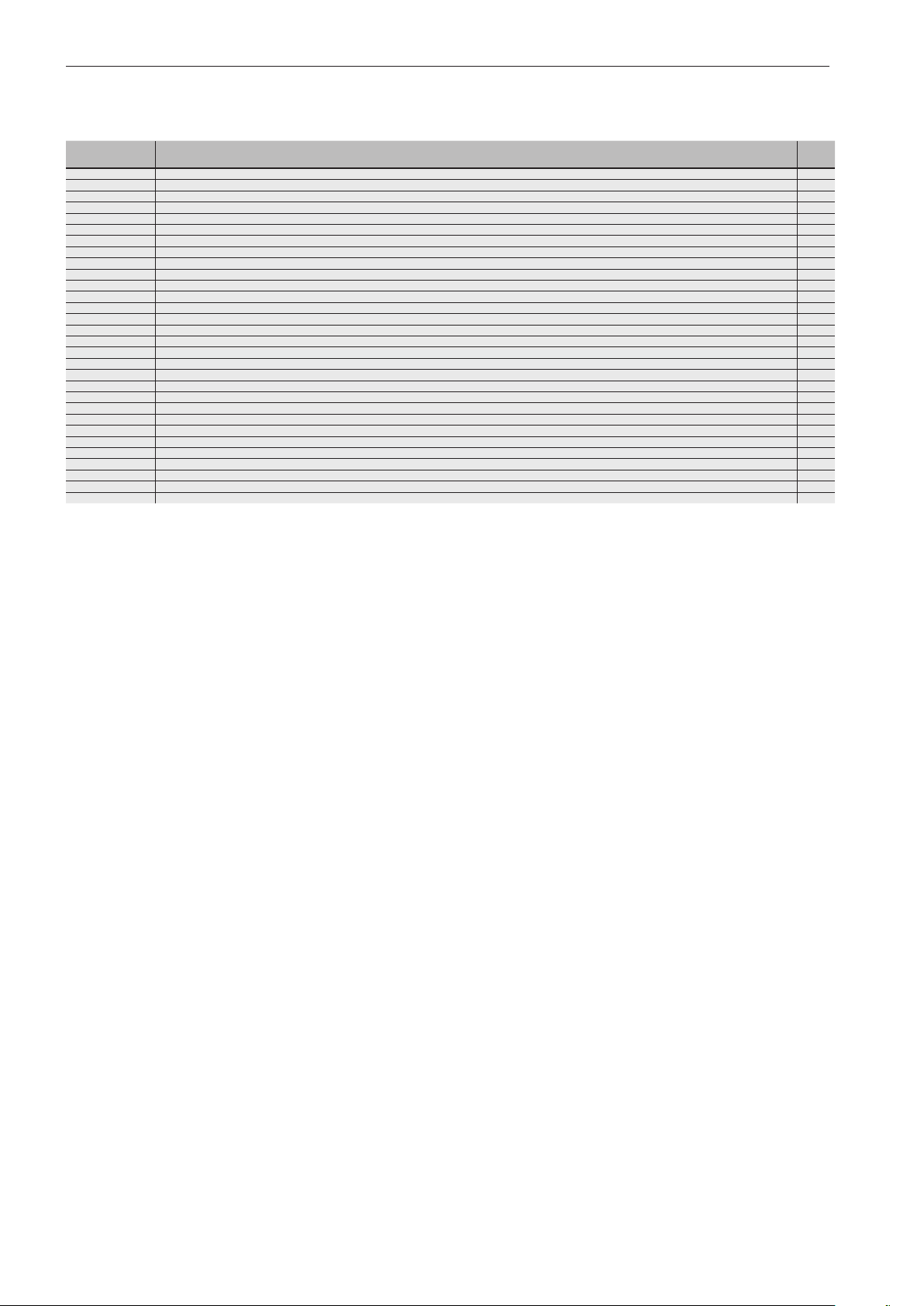
Installation / fitting
3000 (60 Hz: 3600) min
Model DN2G
25-110/0032W 25
25-110/0052W 25
25-110/0072W 25
25-181/0112W 25
25-181/0152W 25
25-181/0222W 25
32-131/0072W 32
32-131/0112W 32
32-131/0152W 32
32-161/0222W 32
32-191/0302W 32
32-191/0402W 32
32-201/0552W 32
40-161/0112W 40
40-161/0152W 40
40-161/0222W 40
40-162/0302W 40
40-161/0302W 40
40-191/0402W 40
40-193/0552W 40
40-192/0552W 40
50-161/0152W 50
50-161/0222W 50
50-161/0302W 50
50-161/0402W 50
65-161/0222W 65
65-161/0302W 65
65-161/0402W 65
65-161/0552W 65
65-161/0752W 65
-1
H L a d e f
1
1
/4445 300 56 180 120 100 11 0 138 210 145 175 90 100 80 150 28
1
/4445 300 56 180 120 100 11 0 138 210 145 175 90 100 80 150 30
1
/4475 300 56 180 120 100 11 0 156 210 145 175 90 100 80 150 32
1
/4465 330 55 180 150 135 140 156 210 145 175 90 100 80 150 43
1
/4500 330 55 180 150 135 140 176 210 145 175 90 100 80 150 44
1
/4525 330 55 180 150 135 140 176 210 145 175 90 100 80 150 47
1
/4460 310 52 180 130 115 130 156 210 145 175 90 100 80 150 35
1
/4460 310 52 180 130 115 130 156 210 145 175 90 100 80 150 40
1
/4495 310 52 180 130 115 130 176 210 145 175 90 100 80 150 41
1
/4535 330 56 180 150 125 140 176 210 145 175 90 100 80 150 48
1
/4560 350 62 180 170 145 160 198 210 145 175 90 100 80 150 60
1
/4625 350 62 180 170 145 160 220 210 145 175 90 100 80 150 70
1
/4670 360 63 180 180 150 170 260 210 145 175 90 100 80 150 107
1
/4465 330 59 180 150 130 145 156 210 145 175 90 100 80 150 45
1
/4500 330 59 180 150 130 145 176 210 145 175 90 100 80 150 45
1
/4525 330 59 180 150 130 145 176 210 145 175 90 100 80 150 48
1
/4545 330 59 180 150 130 145 198 210 145 175 90 100 80 150 59
1
/4545 330 59 180 150 130 145 198 210 145 175 90 100 80 150 59
1
/4620 350 58 180 170 145 160 220 210 145 175 90 100 80 150 73
1
/4685 350 58 180 170 145 160 260 210 145 175 90 100 80 150 105
1
/4685 350 58 180 170 145 160 260 210 145 175 90 100 80 150 105
1
/4510 360 63 200 160 130 160 176 210 145 175 90 125 102 150 48
1
/4535 360 63 200 160 130 160 176 210 145 175 90 125 102 150 51
1
/4560 360 63 200 160 130 160 198 210 145 175 90 125 102 150 61
1
/4625 360 63 200 160 130 160 220 210 145 175 90 125 102 150 71
1
/4560 410 75 230 180 140 165 176 230 160 200 100 148 11 8 150 59
1
/4580 410 75 230 180 140 165 198 230 160 200 100 148 11 8 150 69
1
/4645 410 75 230 180 140 165 220 230 160 200 100 148 11 8 150 79
1
/4690 410 75 230 180 140 165 260 230 160 200 100 148 11 8 150 113
1
/4730 410 75 230 180 140 165 260 230 160 200 100 148 11 8 150 115
min.g min.
øk m n p q r s x
min.
1)
[kg]
1)
Total weight of the pump
Flange connection dimensions according to DIN 2501 PN 10
32
Page 33
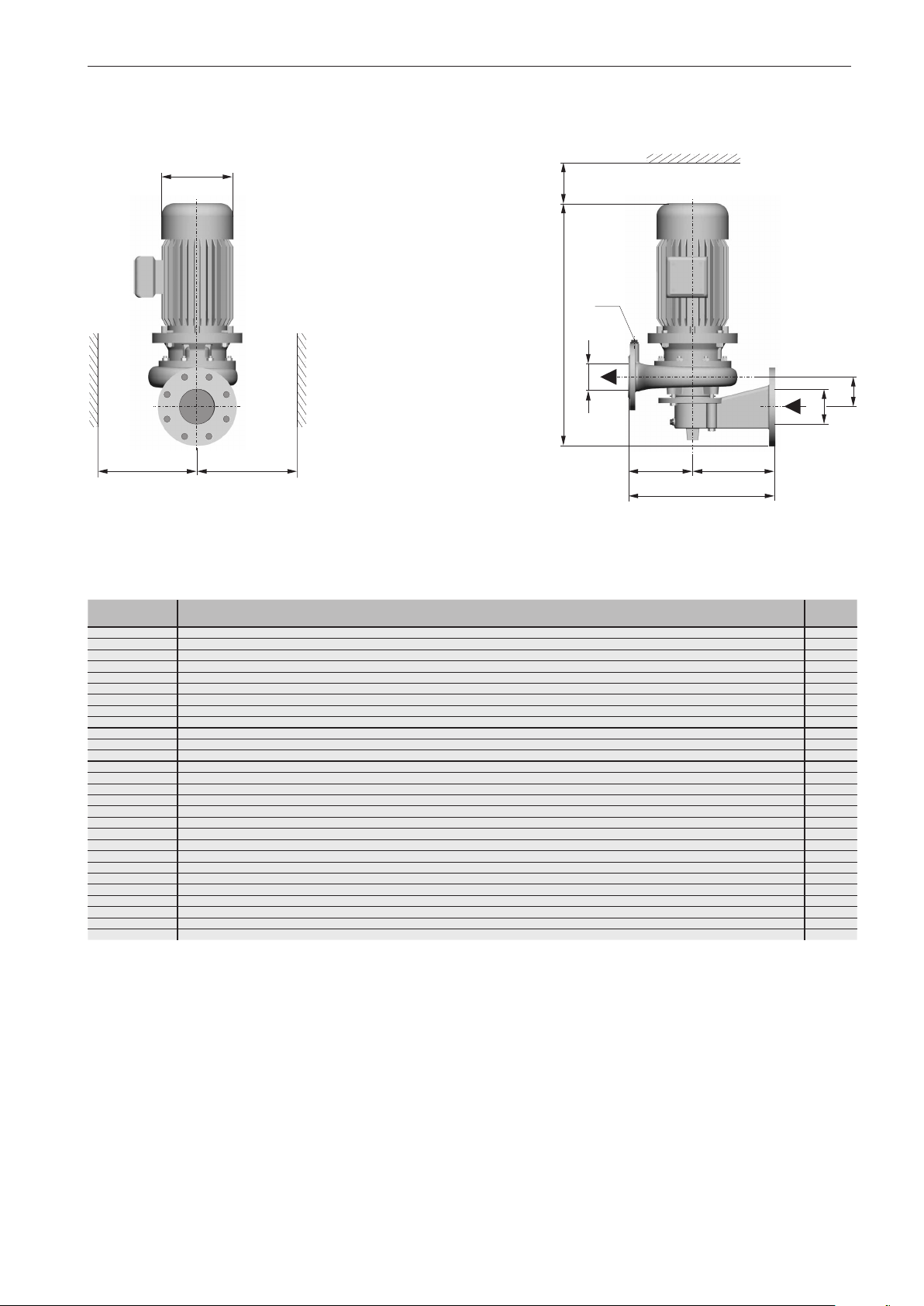
5.2.5 Dimensions of WS model
Installation / fitting
øk
g
f
Figure 5e Dimensions (WS model)
1500 (60 Hz: 1800) min
Model DN
25-110/0034WS 65 25
25-112/0034WS 65 25
25-111/0034WS 65 25
25-162/0034WS 65 25
25-161/0034WS 65 25
25-181/0034WS 65 25
25-183/0034WS 65 25
25-182/0034WS 65 25
25-201/0054WS 65 25
32-161/0034WS 65 32
32-201/0054WS 65 32
32-201/0074WS 65 32
40-161/0034WS 80 40
40-161/0054WS 80 40
40-221/0114WS 80 40
40-221/0154WS 80 40
50-161/0034WS 80 50
50-161/0054WS 80 50
50-161/0074WS 80 50
50-191/0114WS 80 50
50-191/0154WS 80 50
50-241/0224WS 80 50
50-241/0304WS
65-191/0114WS 100 65
65-191/0154WS 100 65
65-201/0224WS 100 65
65-241/0304WS 100 65
65-241/0404WS 100 65
-1
DN
1
80 50
2
x
1
G/
4
H
2
DN
a
1
DN
e
d
L
G
1
1
/
4
1
/
4
1
/
4
1
/
4
1
/
4
1
/
4
1
/
4
1
/
4
1
/
4
1
/
4
1
/
4
1
/
4
1
/
4
1
/
4
1
/
4
1
/
4
1
/
4
1
/
4
1
/
4
3
/
8
3
/
8
1
/
4
3
/
8
3
/
8
3
/
8
1
/
4
3
/
8
3
/
8
H L a d e f
475 300 63 180 120 100 110 138 150 28
475 300 63 180 120 100 110 138 150 28
475 300 63 180 120 100 110 138 150 28
470 330 62 180 150 125 140 138 150 33
470 330 62 180 150 125 140 138 150 34
465 330 62 180 150 135 140 138 150 34
465 330 62 180 150 135 140 138 150 34
465 330 62 180 150 135 140 138 150 34
510 360 69 180 180 150 165 156 150 45
460 330 64 180 150 130 145 138 150 35
510 360 71 180 180 150 170 156 150 46
510 360 71 180 180 150 170 156 150 47
485 360 74 200 160 130 155 138 150 38
515 360 74 200 160 130 155 156 150 44
575 400 85 200 200 165 185 176 150 57
600 400 85 200 200 165 185 176 150 60
495 380 82 200 180 140 175 138 150 44
525 380 82 200 180 140 175 156 150 50
525 380 82 200 180 140 175 156 150 51
560 400 82 200 200 155 175 176 150 56
585 400 82 200 200 155 175 176 150 59
605 420 87 200 220 175 195 198 150 74
645 420 87 200 220 175 195 198 150 79
575 440 91 230 210 165 190 176 150 66
600 440 91 230 210 165 190 176 150 69
615 440 91 230 210 165 190 198 150 72
665 460 93 230 230 185 210 198 150 84
700 460 93 230 230 185 210 220 150 91
min.
g
min.
øk x
min.
1)
[kg]
1)
Total weight of the pump
Flange connection dimensions according to DIN 2501 PN 10
33
Page 34
Installation / fitting
3000 (60 Hz: 3600) min
Model DN
25-110/0032WS 65 25
25-110/0052WS 65 25
25-110/0072WS 65 25
25-181/0112WS 65 25
25-181/0152WS 65 25
25-181/0222WS 65 25
32-131/0072WS 65 32
32-131/0112WS 65 32
32-131/0152WS 65 32
32-161/0222WS 65 32
32-191/0302WS 65 32
32-191/0402WS 65 32
32-201/0552WS 65 32
40-161/0112WS 65 40
40-161/0152WS 65 40
40-161/0222WS 65 40
40-162/0302WS 65 40
40-161/0302WS 65 40
40-191/0402WS 65 40
40-193/0552WS 65 40
40-192/0552WS 65 40
50-161/0152WS 80 50
50-161/0222WS
50-161/0302WS 80 50
50-161/0402WS 80 50
65-161/0222WS 100 65
65-161/0302WS 100 65
65-161/0402WS 100 65
65-161/0552WS 100 65
65-161/0752WS 100 65
1
80 50
-1
DN
G
2
1
1
/
4
1
/
4
1
/
4
1
/
4
1
/
4
1
/
4
1
/
4
1
/
4
1
/
4
1
/
4
1
/
4
1
/
4
1
/
4
1
/
4
1
/
4
1
/
4
1
/
4
1
/
4
1
/
4
1
/
4
1
/
4
1
/
4
1
/
4
1
/
4
1
/
4
1
/
4
1
/
4
1
/
4
1
/
4
1
/
4
H L a d e f
475 300 63 180 120 100 110 138 150 28
475 300 63 180 120 100 110 138 150 31
500 300 63 180 120 100 110 156 150 33
495 330 62 180 150 135 140 156 150 45
530 330 62 180 150 135 140 176 150 46
555 330 62 180 150 135 140 176 150 48
485 310 60 180 130 115 130 156 150 36
485 310 60 180 130 115 130 156 150 41
520 310 60 180 130 115 130 176 150 42
560 330 64 180 150 125 140 176 150 49
590 350 69 180 170 145 160 198 150 62
655 350 69 180 170 145 160 220 150 71
700 360 71 180 180 150 170 260 150 109
495 330 67 180 150 130 145 156 150 48
530 330 67 180 150 130 145 176 150 49
555 330 67 180 150 130 145 176 150 52
575 330 67 180 150 130 145 198 150 62
575 330 67 180 150 130 145 198 150 62
650 350 66 180 170 145 160 220 150 77
715 350 85 180 170 145 160 260 150 108
715 350 85 180 170 145 160 260 150 108
550 360 74 200 160 130 160 176 150 48
575 360 74 200 160 130 160 176 150 53
595 360 74 200 160 130 160 198 150 61
660 360 74 200 160 130 160 220 150 71
595 410 84 230 180 140 165 176 150 59
620 410 84 230 180 140 165 198 150 68
685 410 84 230 180 140 165 220 150 78
730 410 84 230 180 140 165 260 150 11 2
770 410 84 230 180 140 165 260 150 11 4
min.
g
min.
øk x
min.
1)
[kg]
1)
Total weight of the pump
Flange connection dimensions according to DIN 2501 PN 10
34
Page 35
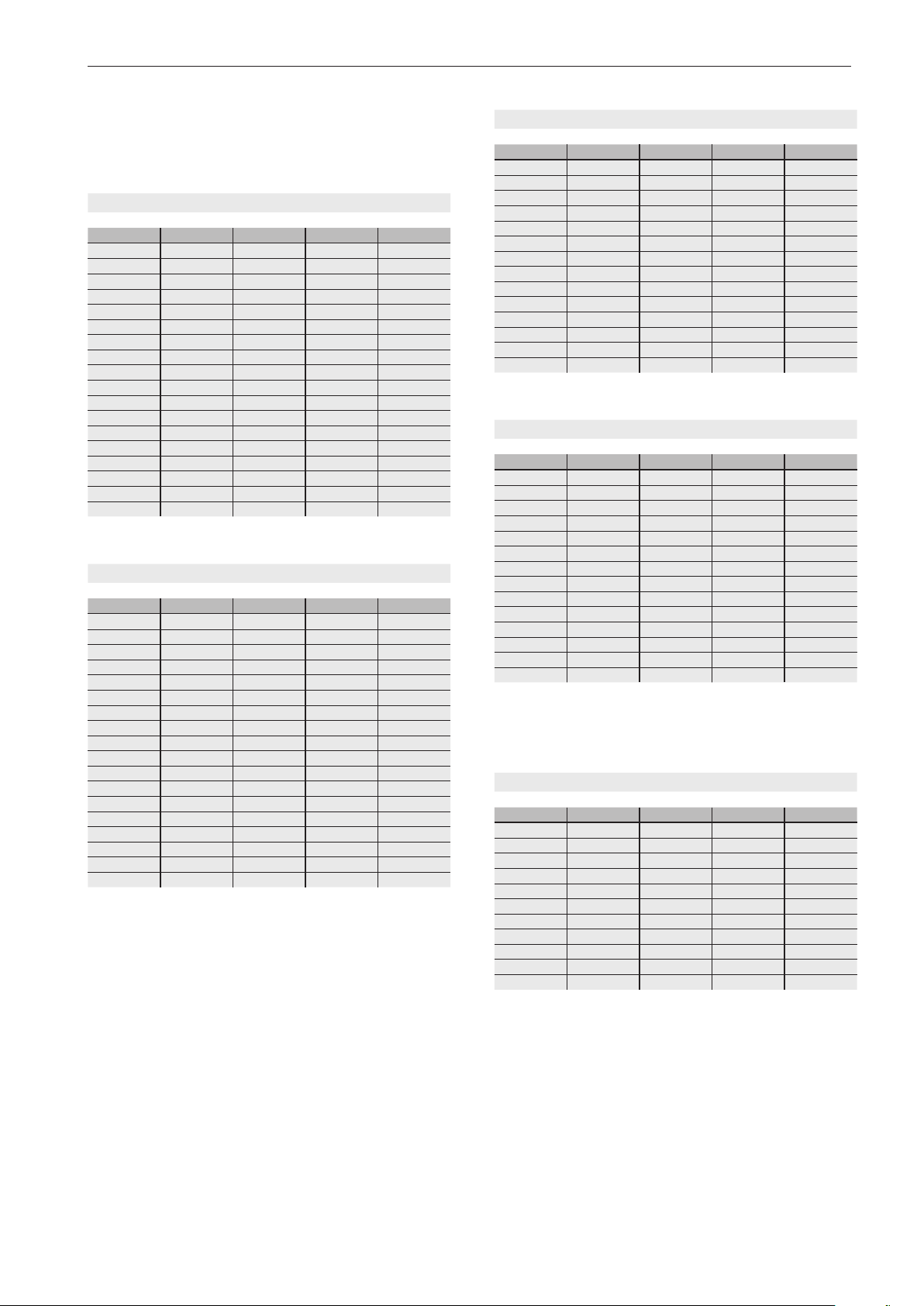
Installation / fitting
5.3 Technical specifications
Model GF/D/W/WS
50 Hz: 1500 min-1 (400 V)
P2 [kW] I [A] IA/I
0.37 1.1 4.5
0.55 1.7 4.8
0.75 2.1 4.8
1.1 2.8 5.2
1.5 3.8 5.6
2.2 5.3 5.9
3.0 7.0 6.2
4.0 9.0 6.8
5.5 11.4 6.6
7.5 15.4 6.8
11.0 22.0 6.9
15.0 30.0 7.3
18.5 37.0 7.0
22.0 44.0 6.9
30.0 54.5 7.0
37.0 66.0 6.8
45.0 82.0 7.0
55.0 95.0 7.0
N
60 Hz: 1800 min-1 (460 V)
P2 [kW] I [A] IA/I
0.44 1.1 4.3
0.66 1.7 4.6
0.9 2.2 4.8
1.3 2.9 5.3
1.8 3.7 5.4
2.6 5.5 6.1
3.6 7.2 6.6
4.8 9.1 7.0
6.6 11.9 6.3
9.0 16.1 6.5
13.2 23.0 6.6
18.0 30.3 7.3
22.2 38.6 6.7
26.4 44.9 6.6
36.0 58.4 6.7
44.4 68.9 6.5
54.0 85.6 6.7
66.0 99.1 6.7
N
3/5
3
3
3
3
3
3
5
5
5
5
5
5
5
5
5
5
5
5
3/5
3
3
3
3
3
3
5
5
5
5
5
5
5
5
5
5
5
5
dB(A)
52
50
50
55
55
59
59
59
63
63
65
65
65
67
68
70
70
71
dB(A)
56
54
54
59
59
63
63
63
67
67
69
69
69
71
72
74
74
75
50 Hz: 3000 min-1 (400 V)
P2 [kW] I [A] IA/I
0.37 1.0 4.6
0.55 1.3 5.3
0.75 1.9 5.6
1.1 2.7 6.1
1.5 3.3 7.0
2.2 4.6 7.5
3.0 6.5 6.5
4.0 8.3 8.4
5.5 11.0 6.3
7.5 15.3 6.5
11.0 20.5 7.0
15.0 27.0 7.1
18.5 32.5 7.3
22.0 40.0 7.8
60 Hz: 3600 min-1 (460 V)
P2 [kW] I [A] IA/I
0.44 1.0 4.4
0.66 1.4 5.6
0.9 1.8 6.1
1.3 2.8 6.3
1.8 3.4 6.7
2.6 4.8 6.6
3.6 6.7 6.2
4.8 8.7 8.1
6.6 11.5 6.0
9.0 15.1 6.3
13.2 21.4 6.7
18.0 28.2 6.8
22.2 33.9 7.0
26.4 41.7 7.5
Model GFC
50 Hz: 1500 min-1 (400 V)
P2 [kW] I [A] IA/I
1.5 3.3 7.6
2.2 4.9 6.6
3.0 6.9 4.6
4.0 9.2 5.3
5.5 12.5 5.4
7.5 17.4 5.3
11.0 22.0 5.8
15.0 30.0 6.0
18.5 37.0 6.5
22.0 42.8 6.5
30.0 57.5 6.0
N
3/5
3
3
3
3
3
3
5
5
5
5
5
5
5
5
N
3/5
3
3
3
3
3
3
5
5
5
5
5
5
5
5
N
3/5
3
3
5
5
5
5
5
5
5
5
5
dB(A)
61
61
63
63
67
67
72
74
74
74
75
75
75
75
dB(A)
65
65
67
67
71
71
76
78
78
78
79
79
79
79
dB(A)
49
49
49
49
49
49
50
50
52
52
52
35
Page 36
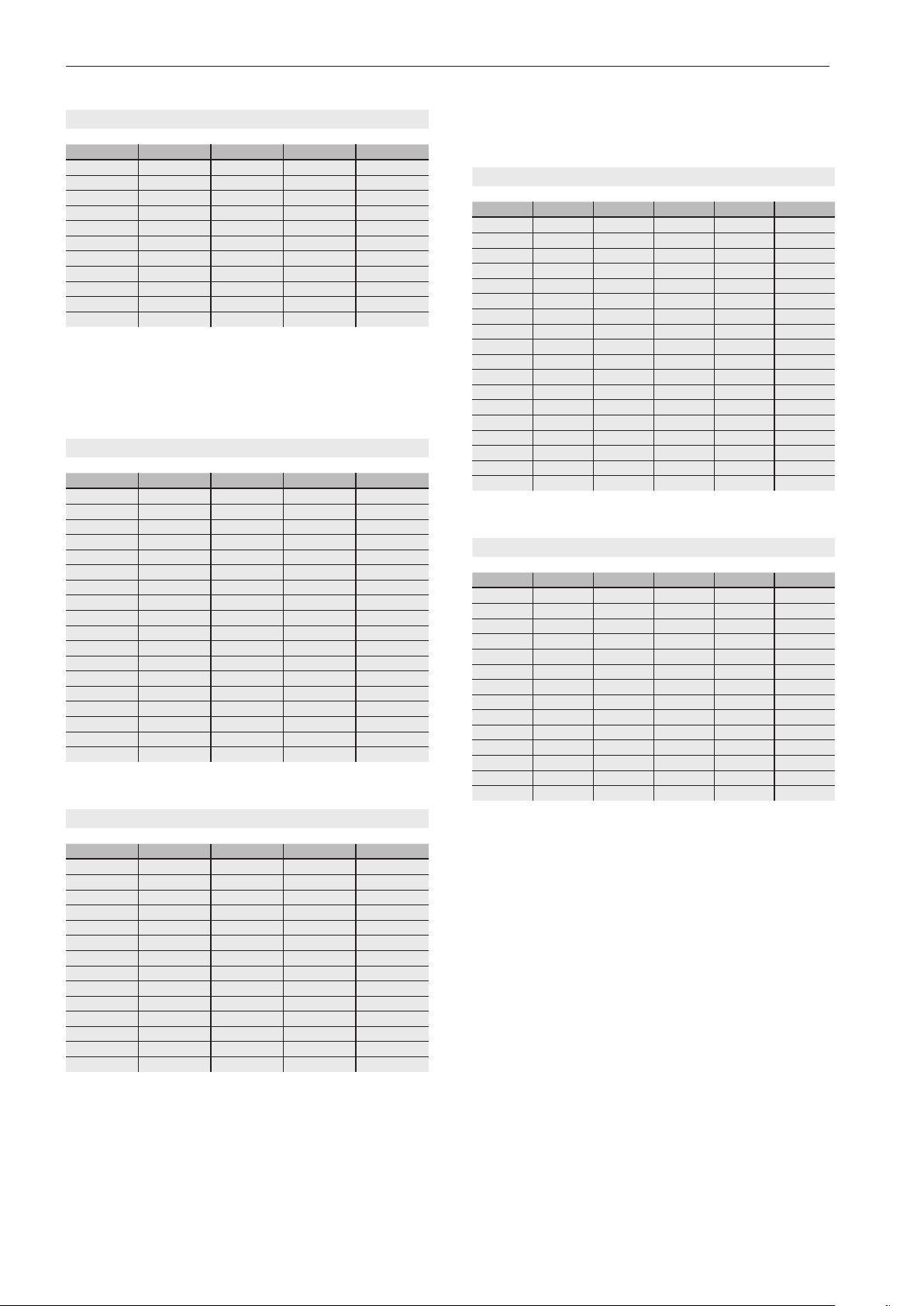
Installation / fitting
60 Hz: 1800 min-1 (460 V)
P2 [kW] I [A] IA/I
1.8 3.5 8.2
2.6 5.0 7.1
3.6 7.2 4.4
4.8 9.6 5.1
6.6 13.0 5.2
9.0 18.2 5.1
13.2 23.0 5.6
18.0 31.3 5.8
22.2 38.6 6.2
26.4 44.7 6.2
36.0 60.0 5.8
Model GF-PM
Motor manufacturer: emod
75 Hz: 1500 min-1 (350 V)
P2 [kW] P1 [kW] I [A]
0,37 0,45 0,8
0,55 0,68 1,18
0,75 0,85 1,43
1,1 1,28 2,15
1,5 1,69 2,95
2,2 2,44 4,3
3,0 3,35 5,7
4,0 4,44 7,7
5,5 5,98 10,6
7,5 8,15 14,2
11,0 11,89 21,5
15,0 16,29 30,5
18,5 19,94 34,3
22,0 23,4 41,0
30,0 31,85 57,0
37,0 39,19 67,0
45,0 47,47 81,0
55,0 57,89 102,0
Model GF-PM
Motor manufacturer: VEM
N
3/5
3
3
5
5
5
5
5
5
5
5
5
3/5
3
3
3
3
3
3
3
3
3
3
3
3
3
3
3
3
3
3
dB(A)
53
53
53
53
53
53
54
54
56
56
56
dB(A)
52
52
52
52
55
55
55
55
59
59
63
63
63
63
65
65
68
68
50 Hz: 1500 min
P2 [kW] P1 [kW] I [A] U [V]
0.37 0.46 0.8 345
0.55 0.67 1.2 350
0.75 0.9 1.5 350
1.1 1.29 2.2 350
1.5 1.7 3.0 340
2.2 2.49 4.5 320
3.0 3.28 5.6 330
4.0 4.32 7.4 340
5.5 5.88 10.5 330
7.5 8.02 12.2 385
11.0 11.69 18.3 375
15.0 15.82 24.8 375
18.5 19.47 30.5 375
22.0 23.06 36.1 380
30.0 31.38 50.5 370
37.0 38.7 59.9 380
45.0 47.02 76.6 365
55.0 57.53 89.5 380
100 Hz: 3000 min
P2 [kW] P1 [kW] I [A] U [V]
0.37 0.46 0.8 300
0.55 0.66 1.1 320
0.75 0.89 1.6 310
1.1 1.29 2.1 320
1.5 1.73 3.2 305
2.2 2.51 4.0 346
3.0 3.39 5.2 348
4.0 4.52 7.3 330
5.5 6.15 10.2 322
7.5 8.29 14.3 314
11.0 11.71 17.7 385
15.0 15.94 24.7 375
18.5 20.07 30.4 385
22.0 23.84 35.7 390
-1
-1
3/5
3
3
3
3
3
3
3
3
3
3
3
3
3
3
3
3
3
3
3/5
3
3
3
3
3
3
3
3
3
3
3
3
3
3
dB(A)
45
47
47
52
52
53
53
56
61
63
63
65
65
67
67
70
70
71
dB(A)
51
51
55
55
59
59
62
64
68
68
69
70
70
75
150 Hz: 3000 min-1 (350 V)
P2 [kW] P1 [kW] I [A]
0,37 0,44 0,74
0,55 0,65 1,1
0,75 0,87 1,46
1,1 1,22 2,17
1,5 1,65 2,8
2,2 2,42 4,3
3,0 3,28 5,8
4,0 4,3 7,7
5,5 5,93 10,2
7,5 8,06 14,3
11,0 11,83 20,1
15,0 15,96 27,8
18,5 19,89 35,1
22,0 23,55 41,6
36
3/5
3
3
3
3
3
3
3
3
3
3
3
3
3
3
dB(A)
61
61
61
61
61
67
67
67
67
67
74
74
74
75
Legend:
P
: Nominal output
2
: Nominal current
I
N
: Starting current
I
A
U: Voltage
dB(A): Sound pressure level (complete pump)
Page 37
5.4 Electrical connection
The electrical connection should only be established by an
electrician.
Important!
In the case of PM motors, observe the operating instructions
included in delivery!
Warning!
An incorrectly established electrical
connection can result in death.
Connect according to DIN VDE 0100;
also comply with DIN VDE 0165 in potentially explosive atmospheres.
The earth, neutral connection, fault current protection circuit,
etc. must
- correspond to the directives of the local public utility company (PUC) and
- function flawlessly according to the electrician's inspection.
The cross-section and voltage drop of the feed line must
comply with the respective regulations.
Installation / fitting
Warning!
Electric current can result in death.
Provide equipotential bonding between
the pump casing and building earth.
5.5 Motor protection
Use a motor circuit breaker or adequate motor protection with
a tripping characteristic according to DIN VDE 0660.
Accommodate the integrated temperature monitors (e.g.
PTC thermistor) in the motor control circuits in such a way
that if the temperature monitor responds it results in switching
off the motor.
Important!
The motor protection switch should be
- regulated for nominal motor current during direct starting,
- introduced into the delta link for star-delta starting and set
to maximum 0.58-times the nominal current.
The standard versions of the motors from 5.5 kW at
1500/1800 min-1 and motors of the UNIBLOCK-GFC and
UNIBLOCK-GF-PM type pumps ex works have a PTC thermistor (see Section 5.7.1, PTC Thermistor Connection).
Caution!
Incorrect warming will damage the
three-phase motor.
Maintain the voltage tolerance of ± 10%
according to DIN EN 60034-1.
Warning!
If the winding protection is triggered, it
can result in a potentially fatal explosive atmosphere.
Do not reactivate the system without
previously checking it and eliminating
the cause of the disturbance.
37
Page 38
Installation / fitting
5.6 Direction of rotation check
Make sure you check the direction of rotation during the initial
commissioning procedure and also at each new installation
location of three-phase pumps. An incorrect direction of
rotation results in decreased pump power output and can
damage the pump.
Caution!
Dry running the pump will destroy the
mechanical seal!
After starting up the pump switch it off
again immediately.
Danger!
The rotating impeller can cut or crush
hands and arms.
Safeguard the pump when checking
the direction of rotation.
Do not reach into the pressure flanges
or the intake port of the pump casing.
Danger!
Risk of potentially fatal explosion during the installation phase.
Provide a constant supply of pumped
media to the feed and pressure pipe as
well as the interior of the pump.
Provide appropriate monitoring measures to ensure this.
Only then should you check the direction of rotation.
It is possible to activate the pump temporarily (no explosion protection) for max. 3 seconds without the risk of dry
running.
Each pump is to be inspected individually in the case of a
control system with multiple pumps.
The direction of rotation
corresponds to the rotation indicator arrow!
Important!
This must rotate clockwise when looking at the motor fan.
In pumps of the UNIBAD-GFC series, the motor shaft has to
rotate clockwise from the direction of the motor cover.
Openings in the intermediate casing allow a glimpse of the
motor shaft.
5.6.1 Change of direction of rotation
The direction of rotation can be changed by swapping two
phases of the motor cable.
38
Page 39
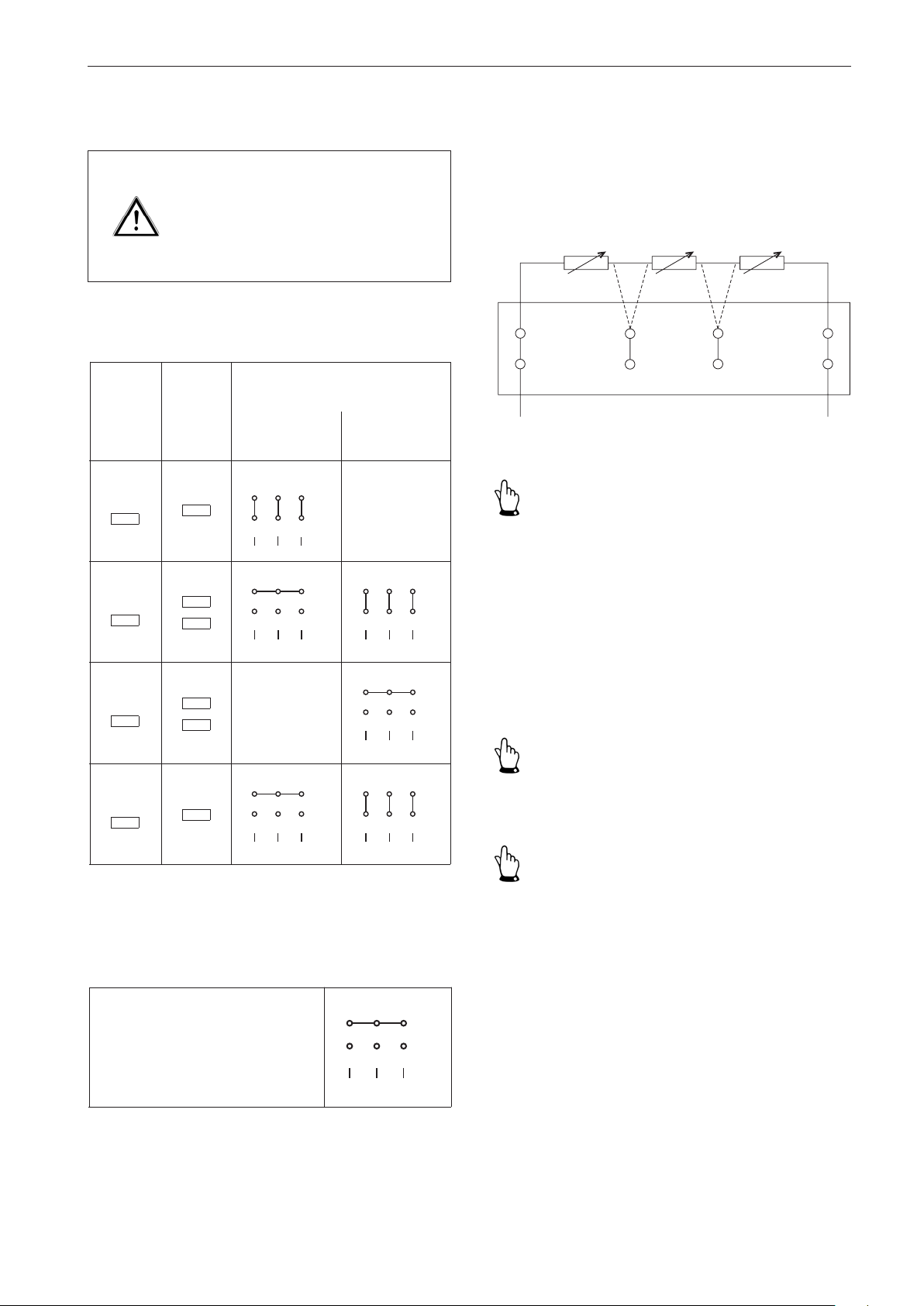
Installation / fitting
W2
U2
V2
L1
L2
L3
U1
V1
W1
W2
U2
V2
L1
L2
L3
U1
V1
W1
W2
U2
V2
L1
L2
L3
U1
V1
W1
W2
U2
V2
L1
L2
L3
U1
V1
W1
W2
U2
V2
L1
L2
L3
U1
V1
W1
W2
U2
V2
L1
L2
L3
U1
V1
W1
3
5
5
5
3
3
W2
U2
V2
L1
L2
L3
U1
V1
W1
3
5.7 Motor connection diagrams
Caution!
An incorrect electrical circuit arrangement will result in failure of the threephase motor.
Observe the circuit arrangement.
Model GF/GFC/D/W/WS
Motor voltage (motor name plate)
Operating
voltage
220-240V
230V
380-420V
400V
Operating
frequency
50Hz
50Hz
60Hz
230/400V
275/480V
5/3
5/3
400/690V
50Hz
655-725V350Hz
60Hz
448-480V560Hz
460-500V560Hz
5/3
50Hz
5.7.1 PTC thermistor connection
Discrepancies can arise due to the various motor manufacturers and motor sizes. Observe the documents accompanying the motor and note the information in the terminal
box cover.
1
A1
A2
2
to the tripping unit
Important!
- Measurement voltage of max. 2.5 V direct current!
- Only operate in connection with a tripping unit!
Use a measuring bridge or ohmmeter to check the resist-
ance.
-
Configuration of terminals A1 and A2 (if available) in the
event of a breakdown of a PTC thermistor.
655-725V
690V
440-480V
460V
Model GF-PM
Voltage supply via frequency converter
Motor voltage/motor frequency
50Hz
60Hz
60Hz
(motor name plate)
300-400 V350-150 Hz
5.8 Frequency converter operation
Important!
Observe the operating instructions included in delivery!
Important!
Do not use frequency converters in explosion-proof areas.
39
Page 40
Installation / fitting
Important!
Pumps of the UNIBAD-GF-PM type only for operating frequency converters.
Up to 30/36 kW, frequency converters can also be connected
in a direct mounting configuration (UNIBAD-GFC models are
only wall-mounted).
Possible frequency regulation of the pumps in a range of
30 to 50 Hz (30 to 60 Hz) is dependent on the operating
conditions.
Frequency regulation of pumps of the UNIBLOCK-GF-PM
type depending on the operating conditions
Important!
Frequency converters must comply with the EU's low voltage
and EMC directives.
Ensure measures are in place for complete ventilation during
the laying procedure.
Pressure pipes
-
lay in a frost-free configuration,
secure and
-
connect so they are stress-free.
-
Pipe forces and moments should not affect the pump.
Install a ...
- gate valve immediately in front of the pump to close off
the pipes. This enables the pump to be removed when the
pipes are full.
- non-return valve between the pressure flange and gate
valve. This prevents the pumped medium from flowing
back after shutting off the pump and also it avoids liquid
slugging.
5.11 Frost protection
Use AC / DC sensitive residual current circuit breakers if
necessary.
5.9 ETS X4
For the mounting and electrical connection of the ETS X4,
see the included operating instructions.
5.10 Laying the pipes
Lay the pressure pipes in accordance with the applicable
regulations and the relevant accident prevention regulations.
Warning!
Escaping hot pumped media is potentially fatal.
Do not exceed the pipe forces.
Notice!
The effects of frost can damage the filled pump.
Empty pumps during prolonged periods of inactivity.
Caution!
Escaping pumped media can burn
hands and arms.
Ensure the pump casing is free from
pressure.
Only then should you empty the
pump.
For UNIBLOCK-GFC pumps
- see section 9.1 'Disassembly for draining',
- Attach the cooling pipes according to section 9.2 'Assembly
before recommissioning'.
40
Page 41
6 Commissioning
Inspect the pump before commissioning and conduct a
functional check. When doing this pay special attention to
the following:
- Turn the motor shaft repeatedly by hand!
- Never allow the pump to run dry!
- Are the pump and pipelines properly connected?
- Has the electrical connection been established in accordance with the applicable
regulations?
- Is the temperature monitor connected (if
available)?
- Is the motor circuit breaker set correctly?
- Is the ETS X4 connected (if available)?
- Is the direction of rotation of the pump also
correct when operated via an emergency
generator?
- Are the gate valves open that are required
for operation?
- Is the pump properly mounted?
- Are the inlets and outlets of the pumping
station free from danger and have they
been inspected?
Commissioning
Danger!
Air bubbles or accumulations of gas
around the mechanical seal create a
dangerous explosive atmosphere.
Provide a constant supply of pumped
media to the feed and pressure pipe as
well as the interior of the pump.
Provide appropriate monitoring measures to ensure this.
Important!
Alternately operate installed reserve pumps by using the
controller.
This ensures the operational readiness of the pumps.
6.1 Operating modes and connecting frequency
All models are designed for operating mode S1 (continuous
operation) with a filled pump.
Caution!
A hot pump casing and hot suction
cover can burn hands and arms.
Do not touch pumps that deliver hot
water.
Take precautionary measures to prevent burning.
Caution!
Dry running the pump will destroy the
mechanical seal!
Before starting the pump fill the pump
and supply pipe with the pumped
medium.
Then de-aerate.
Notice!
Prolonged operation against closed gate valves heats up
the pumped medium and the pump.
Open the gate valves before operation.
Danger!
Operating the pump with closed shut
off valves creates a dangerous and
explosive atmosphere.
Open the gate valves before operation.
41
Page 42

Commissioning
Important!
Use a motor circuit breaker or corresponding motor protection
with a tripping characteristic according to DIN VDE 0660.
Do not exceed ten connecting procedures per hour. This
prevents a sharp increase in temperature in the motor and
an excessive load on the pump, motor, seals and bearing.
Contact the respective manufacturer with regard to the permissible switching frequency for any starter device.
6.2 Starting up
To start the pump
1. Close the gate valves and shut-off cocks
of the manometer,
2. Switch on the motor,
3. Open the shut-off cocks of the manometer.
Only turn the gate valves slightly if the pressure pipe is empty.
If the pipe is full, open until the permissible motor load is
reached (compare the ammeter display with the details on
the motor name plate!).
42
Page 43
7 Maintenance / cleaning
Maintenance and cleaning work should only be implemented
by specialist personnel. These personnel are to be provided with personal protective equipment (e.g. protective
gloves).
Maintenance / cleaning
Notice!
Pumped media can be hazardous to health.
Always wear personal protective equipment such as protective gloves and glasses.
Important!
According to EN 60204-1 a person is considered as being
a specialist if they
- are able to use their professional training, knowledge and
experience as well as knowledge of the relevant standards
to assess the work they have been assigned and
- are also able to identify any potential dangers.
Important!
Before maintenance and cleaning work, you must observe
section 3.5 "Shut off procedures."
Only use appliances and tools that are expressly intended
for this work.
Clean and maintain the pump in regular intervals. This will
ensure trouble-free operation of the pump.
Danger!
The rotating impeller can cut or crush
hands and arms.
Allow the impeller to come to a complete
standstill.
Secure the pump from rolling and toppling over.
The pump is subjected to vibrations during operation, which
can cause the screw and clamp connections to become
loose. Inspect the pump in regular intervals for any loose
connections (recommendation is every 6 months for a singleshift operation). Remove any dust deposits and impurities
on a regular basis.
Caution!
Injuries may be caused when maintaining and cleaning the pump.
Observe the safety regulations and
the generally recognised "codes of
practice".
7.1 Maintenance
When conducting maintenance and repair work watch out
for:
- crushing hazards and
- dangers caused by electric current.
Decontaminate the pump after pumping any media that is
hazardous to health.
Important!
Only authorised workshops/persons may work on explosion-proof pumps while using original parts from the manufacturer.
If not, this will result in the expiration of the explosion protection certificate.
43
Page 44
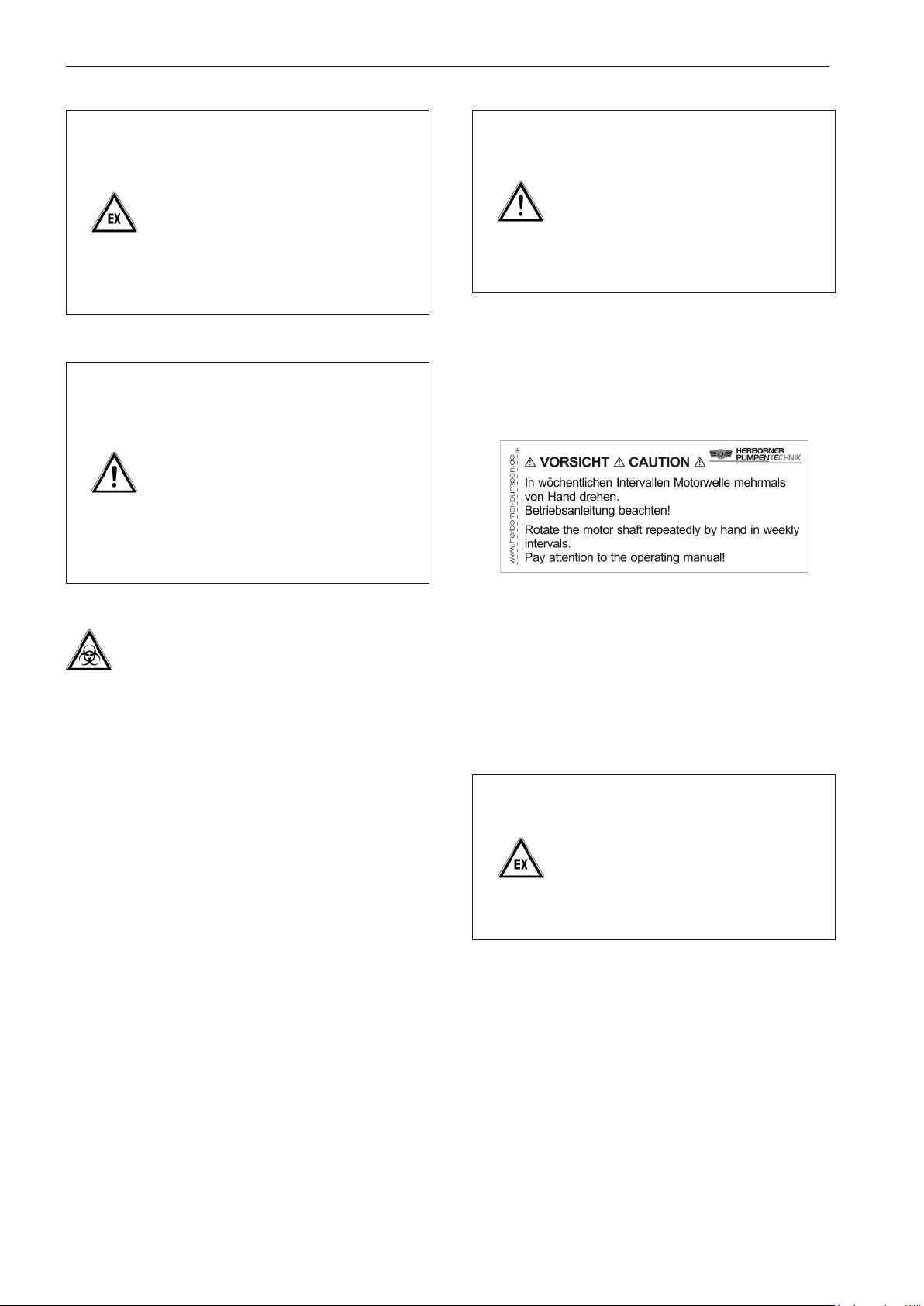
Maintenance / cleaning
Danger!
Flying sparks may cause a potentially
fatal explosion.
Before dismantling the pump in potentially explosive atmospheres make sure
the structure is adequately aerated.
If the pump is dismantled, carry out
extensive repair and maintenance work
at a separate location.
Warning!
When the pump is removed from the
pipe network there is a risk of toppling
which can result in serious injury.
Secure the pump during transport using
separate lifting accessories.
Only set up the pump on a sufficiently
solid surface that is level in all directions. Also secure it to prevent it from
toppling over.
Caution!
Insufficient rotary motion of the motor
shaft leads to the impeller becoming
jammed and a failure of the mechanical seal!
To counteract this rotate the motor
shaft repeatedly by hand in weekly
intervals.
In addition, the following label can be found on the motor:
Important!
Collect any waste and emissions in appropriate containers
and dispose of them properly.
7.2 Maintenance instructions for prolonged periods of inactivity
Protect the pumps from atmospheric influences (UV light,
sunlight, high humidity levels, frost, etc.).
The points specified in section 6 'Commissioning' must be
fulfilled before restarting the pumps.
Figure 6 Dry running label
The label says that the motor shaft should be turned several
times by hand at weekly intervals and the operating instructions should be observed!
Follow the instructions on the label.
Danger!
A failure of the mechanical seal can
create a potentially fatal explosive
atmosphere.
Ensure the proper function of the
mechanical seal by monitoring it
regularly.
44
Page 45
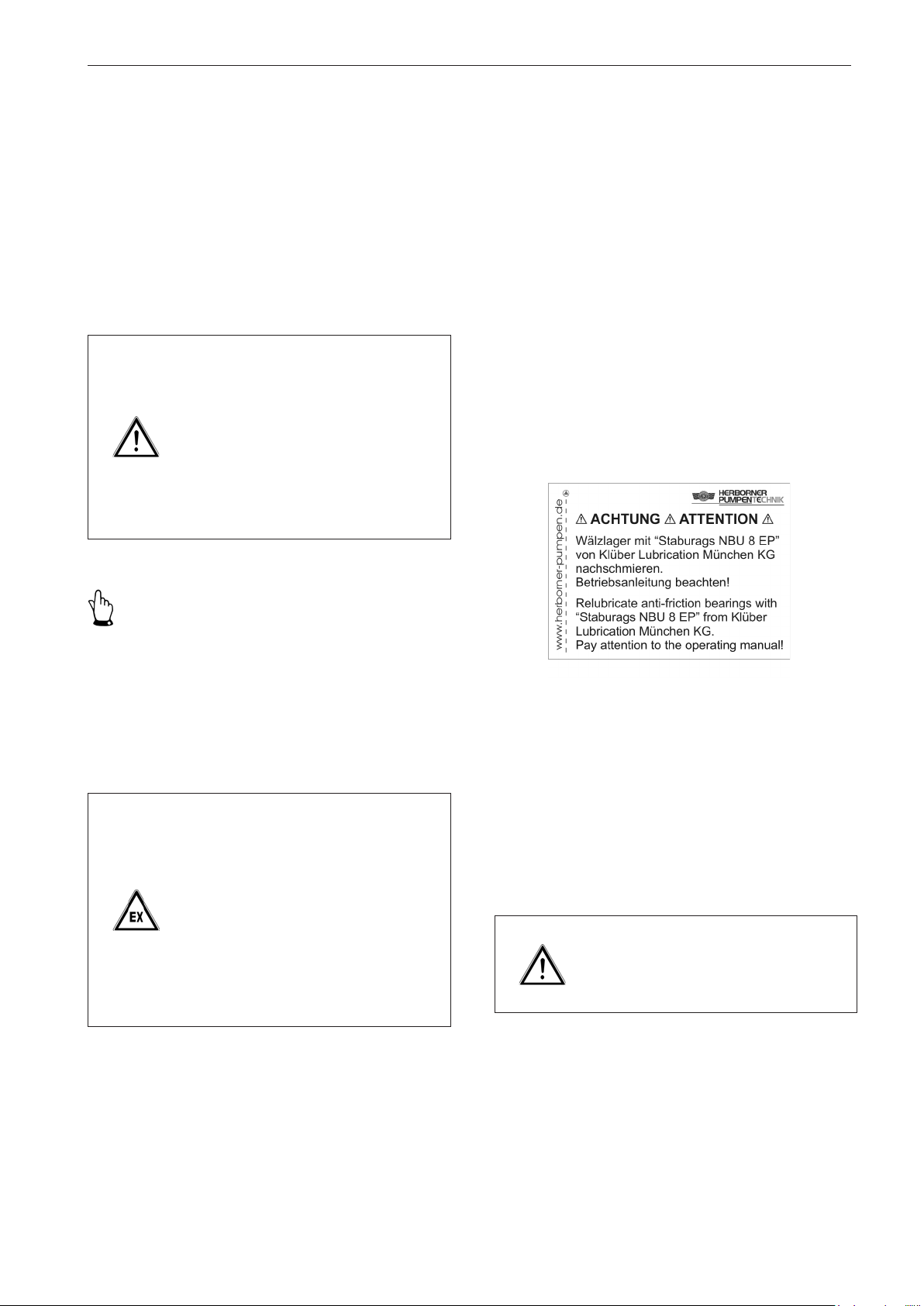
Maintenance / cleaning
For pump controllers it is recommended to programme
an automatic start up every 48 hours for a maximum of 3
seconds.
A start up procedure at approximately 5 Hz is advisable for
operation with frequency converters.
7.3 Bearing lubrication
Anti-friction bearings are provided pre-lubricated.
Danger!
High magnetic forces during the disassembly and assembly of PM motors
can lead to severe personal injury and
property damage.
Before disassembly and assembly, see
Section 9, Disassembly/Assembly.
Observe the operating instructions
included in delivery!
7.3.1 Relubrication unit
Depending on the motor manufacturer a standard relubrication
unit is available for motors operating at 1500 (1800) min
-1
- from 1.1 kW for both bearings or
- from 1.1 kW for the anti-friction bearing (drive side) and
from 7.5 kW for both bearings.
- For both bearings in the case of pumps of the type UNIBAD-GFC.
Motors that cannot be relubricated are those rated
- 0.55 (0.66) and 0.75 (0.9) kW
- 3000 (3600) min
-1
The following label is found on the motor if a relubrication
unit is present:
Important!
Anti-friction bearings that are used at a speed of
-1
- 1500 (1800) min
are to be re-lubricated or replaced, if
necessary, after 20,000 hours of operation
- 3000 (3600) min
-1
are to be re-lubricated or replaced, if
necessary, after 10,000 hours of operation
however, this should be every 3 years at the latest.
Danger!
Insufficient lubrication of the anti-friction bearings in the explosion protection
zone can result in a potentially fatal
explosive atmosphere.
Exchange anti-friction bearings that are
subjected to a speed of 1500 (1800)
-1
min
after every 20,000 hours of operation and after every 10,000 hours of
operation if they are are subjected to a
speed of 3000 (3600) min
-1
.
Figure 7 Relubrication label
The label says that the anti-friction bearing should be
relubricated using Staburags NBU 8 EP of Klüber Lubrication München KG and the operating manual should be
observed!
Follow the instructions on the label.
Warning!
Lubricant is hazardous to health.
Do not swallow lubricant.
45
Page 46
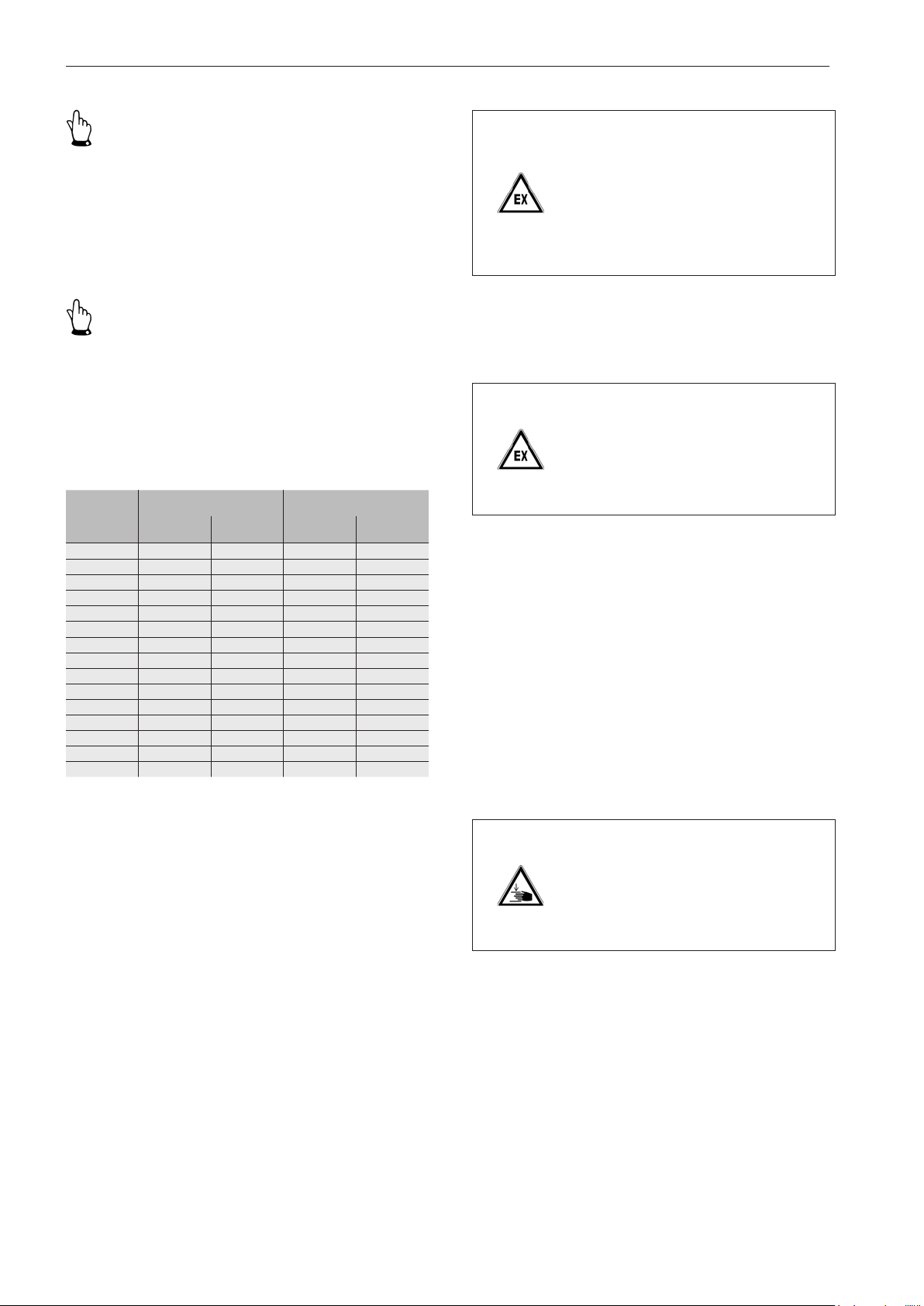
Maintenance / cleaning
Important!
- Do not over-lubricate the bearing.
- Dispose of any lubrication properly.
When using in service water or untreated water contact the
manufacturer with regard to lubrication selection.
Important!
Use grease guns for conical grease nipple H according to
DIN 71412.
Observe the lift quantities of the grease guns!
7.3.2 Greasing intervals
Anti-friction bearing
Motor [kW]
1.1/1.3 5000 7 10000 3
1.5/1.8 5000 7 10000 3
2.2/2.6 5000 10 10000 5
3.0/3.6 5000 10 10000 5
4.0/4.8 5000 10 10000 5
5.5/6.6 4000 16 8000 8
7.5/9.0 4000 16 8000 8
11.0/13.2 3500 22 7000 11
15.0/18.0 3500 22 7000 11
18.5/22.2 3000 32 6000 13
22.0/26.4 3000 32 6000 13
30.0/36.0 3000 40 6000 18
37.0/44.4 3000 50 6000 20
45.0/54.0 3000 50 6000 20
55.0/66.0 3000 55 6000 25
Greasing
interval [h]
(drive side)
Grease quantity
[g]
Anti-friction bearing
(non drive side)
Greasing
interval [h]
Grease quantity
[g]
Danger!
A failure of the mechanical seal can
create a potentially fatal explosive
atmosphere.
Ensure the proper function of the
mechanical seal by monitoring it
regularly.
If monitoring units are installed for the mechanical seal check
their function.
Danger!
Leaky static seals can create a potentially fatal explosive atmosphere.
Check the leak tightness of seals in
regular intervals.
7.5 Cleaning
Remove any sediment deposits when dismounting or dismantling the pump using mechanical means if necessary.
Doing this will ensure flawless operation.
Before decomissioning and storing the pump after a prolonged period of operation rinse it thoroughly with clear water
and then clean it carefully. Hardened dirt deposits, limescale
etc. could block the impeller and the motor shaft.
When cleaning centrifugal pumps that are used in the food
industry or in the supply of drinking water use an appropriate
disinfectant or cleaning agent.
7.4 Seals
In general a mechanical seal does not require maintenance.
Only exchange the mechanical seal as a complete unit. This
ensures optimal shaft sealing.
46
Danger!
The rotating impeller can cut or crush
hands and arms.
Observe section 3.5 "Shut off procedures."
Page 47
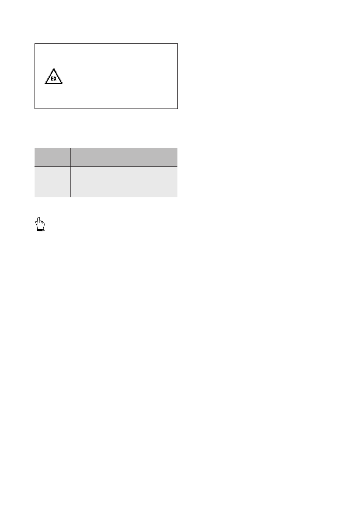
Danger!
Incorrect heating of the three-phase
motor can create a potentially fatal
explosive atmosphere.
It is imperative that the motor is kept
clean. This will ensure adequate aeration.
7.6 Tightening torques for nuts and bolts
Maintenance / cleaning
Thread
M8 18.5 23.0 32.0
M10 37.0 46.0 64.0
M12 57.0 80.0 110.0
M16 135.0 195.0 275.0
M20 230.0 385.0 540.0
Stainless (A4)
[Nm] [Nm] [Nm]
Non-stainless
8.8 10.9
Important!
Tighten all nuts and bolts (clockwise) during assembly as
prescribed.
7.7 Disposal
The pump and individual components of the pump are to be
disposed of in an environmentally-friendly manner:
- Contact your public or private disposal companies for
further information.
- If this is not possible, the pump can be returned to the
manufacturer.
47
Page 48
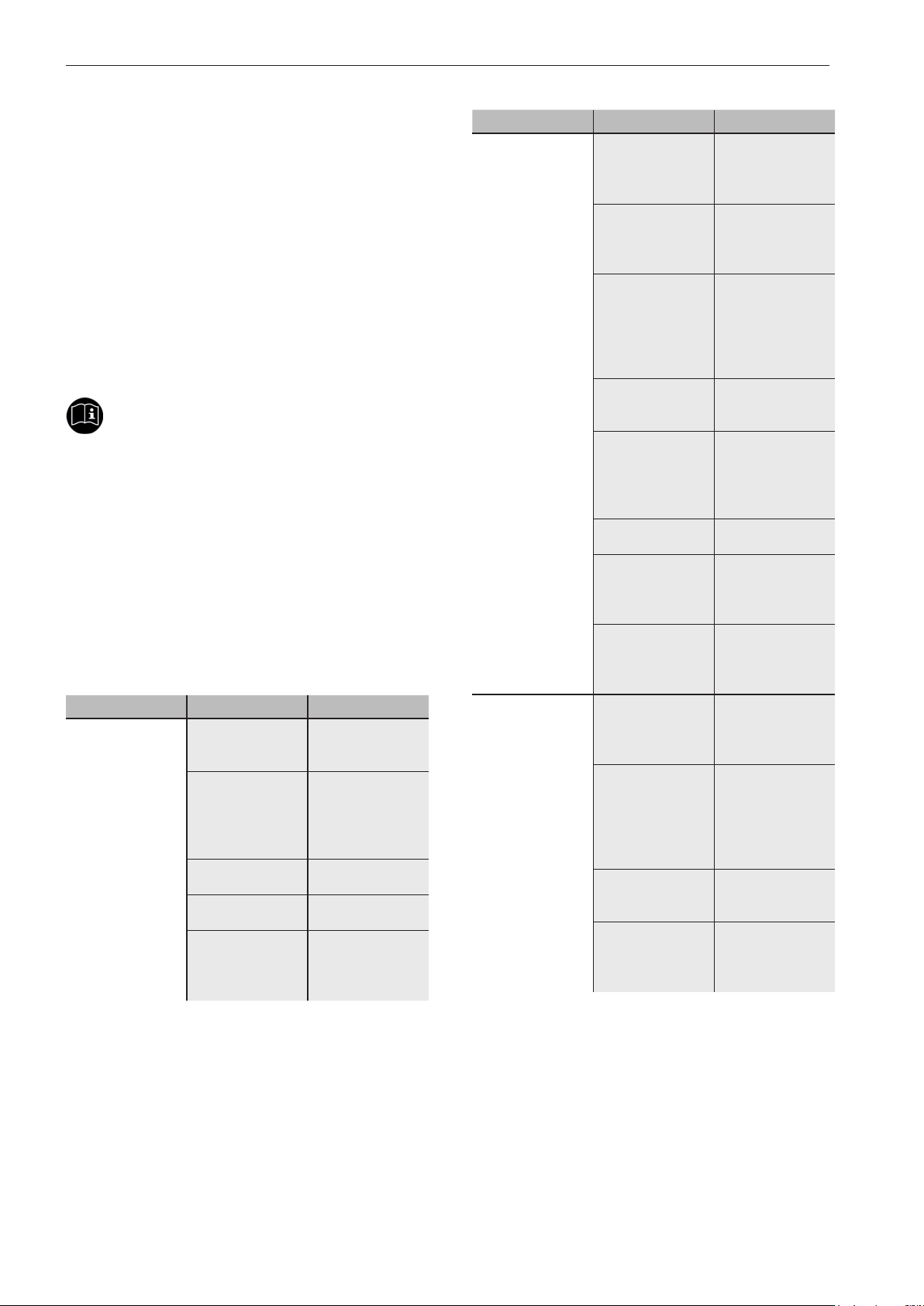
Disturbance / cause / trouble shooting
8 Disturbance / cause / trouble
shooting
The facts and information described in this manual with
regard to "disturbance, cause and trouble shooting" are
addressed to specialists (see the definition in section 2.4
'Safety measures') in terms of
- Electrical/electronics
- Mechanical/maintenance.
These personnel are to be provided with the appropriate
tools and inspection equipment.
If the specified measures prove to be unsuccessful, please
contact the manufacturer.
Important!
Before maintenance and repair work, you must observe
section 3.5 "Shut off procedures."
Only use appliances and tools that are expressly intended
for this work.
Operational disturbances are not anticipated if this manual
is complied with in full.
Only dismantle the pump if all other measures have failed.
If malfunctions are still evident, please contact our customer
service department.
Disturbance Cause Trouble shooting
Pump doesn't
pump! Danger of
running dry!
The pump and/or
pipeline is not
completely filled.
Supply pipe
and/or impeller
obstructed.
Motor doesn't run. Check the electri-
Gate valves
closed.
Head too high. Check the plant
De-aerate and
fill the pump and
pressure pipe.
Clean the supply.
Remove any
sediment deposits from the
pump/pipeline.
cal installation.
Open gate valves.
for any impurities
and/or the layout
of the pump.
Disturbance Cause Trouble shooting
The delivery of
the pump is too
low.
Pump vibrates or
makes a noise.
Density of the
pumped medium
is too high.
Concentration
of air/gas in the
pumped medium
is too high.
Incorrect direction
of rotation of the
pump.
Impeller is loose
or worn.
The pump pumps
against high pressure.
Gate valves
closed too far.
Pipeline and/or
pump obstructed.
Running on two
phases.
Concentration
of air/gas in the
pumped medium
is too high.
Incorrect direction
of rotation of the
pump.
Impeller is loose
or worn.
Pump doesn't
operate in the
specified operating range.
Dilute the
pumped medium
or alter the process.
Further enquiry is
necessary.
Check the direction of rotation
and exchange
two phases to the
motor if necessary.
Inspect the impeller and replace if
necessary.
Measure the
pressure. Change
the configuration,
check the layout
of the pump.
Turn gate valves
back.
Check the
pipeline and/or
pump and clean if
necessary.
Exchange the
defective locking
device or check
the connections.
Further enquiry is
necessary.
Check the direction of rotation
and exchange
two phases to the
motor if necessary.
Inspect the impeller and replace if
necessary.
Check the operating conditions.
48
Page 49
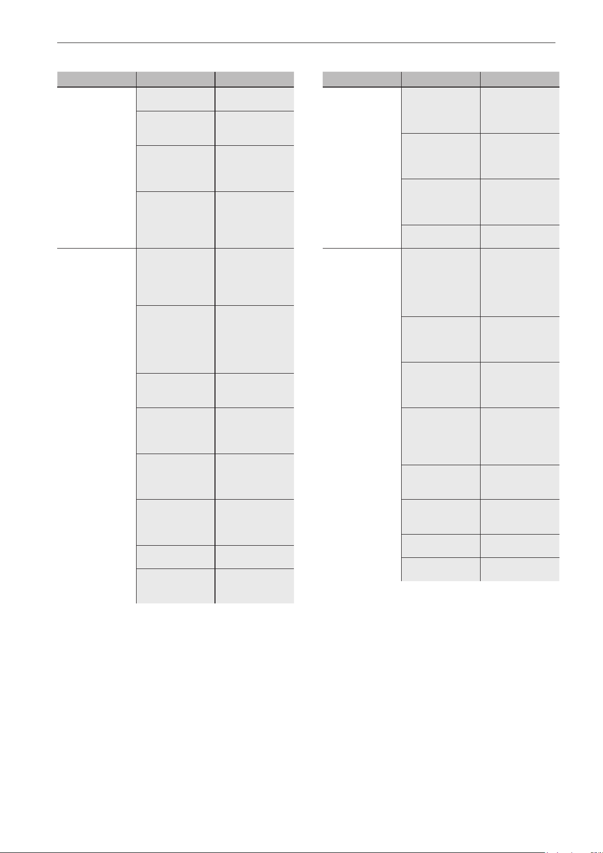
Disturbance / cause / trouble shooting
Disturbance Cause Trouble shooting
Pump vibrates or
makes a noise.
Pump runs but
immediately
switches off.
Anti-friction bearing defective.
Anti-friction bearing not lubricated
properly.
Pump installed
under tension.
Cavitation Check supply
The motor circuit
breaker has been
triggered. Insufficient cooling of
the motor.
The motor circuit
breaker has been
triggered. Incorrect direction of
rotation of the
pump.
Power input too
high.
Density of the
pumped medium
is too high.
Pump doesn't
operate in the
specified operating range.
An obstructed
pump has triggered the motor
protection relay.
Pump switches
too often.
Motor connected
incorrectly.
Exchange antifriction bearing.
Clean anti-friction
bearing and relubricate.
Connecting pipes
must be laid in
an unstressed
manner.
for obstructions.
Check the duty
point and adjust if
necessary.
Provide adequate
motor cooling.
Check the direction of rotation.
Check the free
movement of the
pump.
Dilute the
pumped medium
or alter the process.
Check the operating conditions.
Check the free
movement of the
pump.
Observe operating mode.
Connect motor to
correct operating
voltage.
Disturbance Cause Trouble shooting
Bearing becomes
hot
Electric motor is
overly warm.
Bearing running
without lubrication:
lack of grease.
Too much grease
in the bearing
Pump installed
under tension.
Anti-friction bearing defective.
Incorrect direction
of rotation of the
pump.
Pump doesn't
operate in the
specified operating range.
Density of the
pumped medium
is too high.
Supply pipe
and/or impeller
obstructed.
Motor not powerful enough.
Motor connected
incorrectly.
Coolant temperature > 40 °C.
Pump switches
too often.
Top up grease,
replace bearing if
necessary.
Remove surplus
grease until the
balls are just covered by grease.
Connecting pipes
must be laid in
an unstressed
manner.
Exchange antifriction bearing.
Check the direction of rotation
and exchange
two phases to the
motor if necessary.
Check the operating conditions.
Dilute the
pumped medium
or alter the process.
Clean the supply.
Remove any
sediment deposits from the
pump/pipeline.
Replace motor
with a more powerful model.
Connect motor to
correct operating
voltage.
Check ventilation
paths.
Observe operating mode.
49
Page 50
Disassembly / assembly
9 Disassembly / assembly
The pump is predominantly manufactured from steel. Dispose of the pump, oils and any cleaning agents in accordance
with the applicable local environmental regulations.
Cleaning implements (such as brushes, rags, etc.) are to be
disposed of in accordance with the applicable environmental
regulations or manufacturer's instructions.
Danger!
Due to the magnetic fields of PM motors, there is an acute danger for people with pacemakers in the vicinity of
the rotor when the motor is open.
People with pacemakers may not enter
this area.
Observe the operating instructions
included in delivery!
Important!
Refrain from using excessive force while disassembling and
assembling the pump.
9.1 Disassembly
It is possible to disassemble the interchangeable module
of the pump (see section 1.2 'Exploded view') without loosening the intake connection and pressure flange from the
pipework. The interchangeable module consists of a block
motor (802), intermediate casing (113), impeller (230) and
mechanical seal (433).
Warning!
Electric current can result in death.
Disconnect the block motor (802) according to the 5 safety rules.
Danger!
High magnetic forces during the disassembly and assembly of PM motors
can lead to severe personal injury and
property damage.
Repairs may only be performed by
qualified personnel.
Disassemble the rotor using only the
tool constructed especially for this
purpose.
Observe the operating instructions
included in delivery!
Important!
Tighten all nuts and bolts (clockwise) during assembly as
prescribed (see section 7.6 'Tightening torques for nuts
and bolts').
The five safety rules are as follows:
1. Disconnect.
2. Secure against reactivation.
3. De-energise.
4. Earth and short-circuit.
5. Cover or shield any adjacent live parts.
Caution!
Escaping pumped media can burn
hands and arms and flood the area.
Close pressure and suction side gate
valves.
50
Page 51
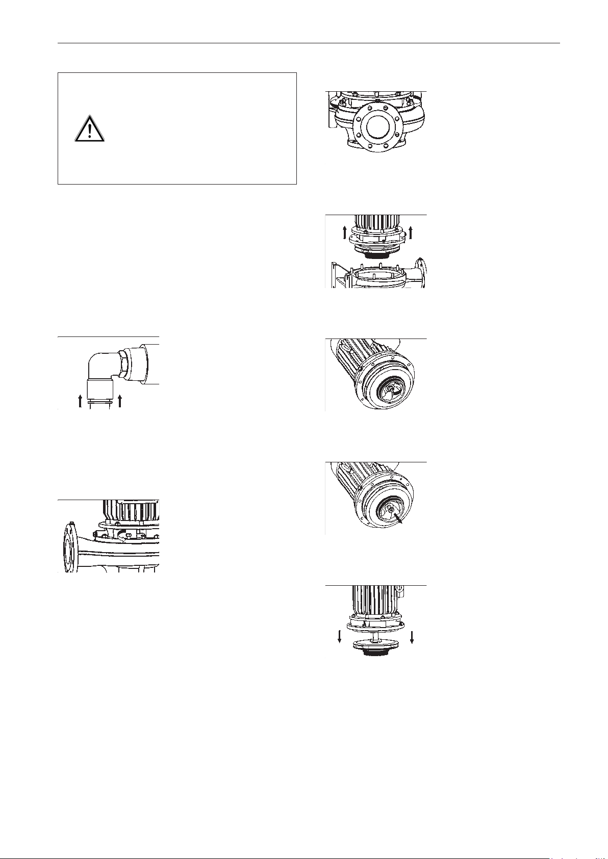
Caution!
Escaping pumped media can burn
hands and arms.
Ensure the pump casing is free from
pressure.
Only then should you empty the
pump.
In the case of the design with the base rail, first loosen the
connecting bolts from the block motor (802) and rail (593).
Emptying the pump UNIBLOCK-GFC:
De-aerate the pump by opening the ball valve (006).
Then loosen the cooling water pipe (704) on the pump casing
(101) in the following way:
Disassembly / assembly
2.
Prise the complete interchangeable module on the
intermediate casing (113)
from the centering of the
pump casing (101) using two
jack screws.
3.
Remove the loosened interchangeable module from the
pump casing (101).
4.
Press the pressure ring backwards. Then pull the cooling water pipe (704) in the
opposite direction from the
right angle connector. Then
release the pressure ring.
After emptying the pump, loosen the return pipe (704) on
the intermediate casing (113).
1.
Loosen the connecting bolts
from the pump casing (101)
and intermediate casing
(113).
Loosen the nut (920).
5.
Remove the washer (554).
6.
Extract the impeller (230).
51
Page 52
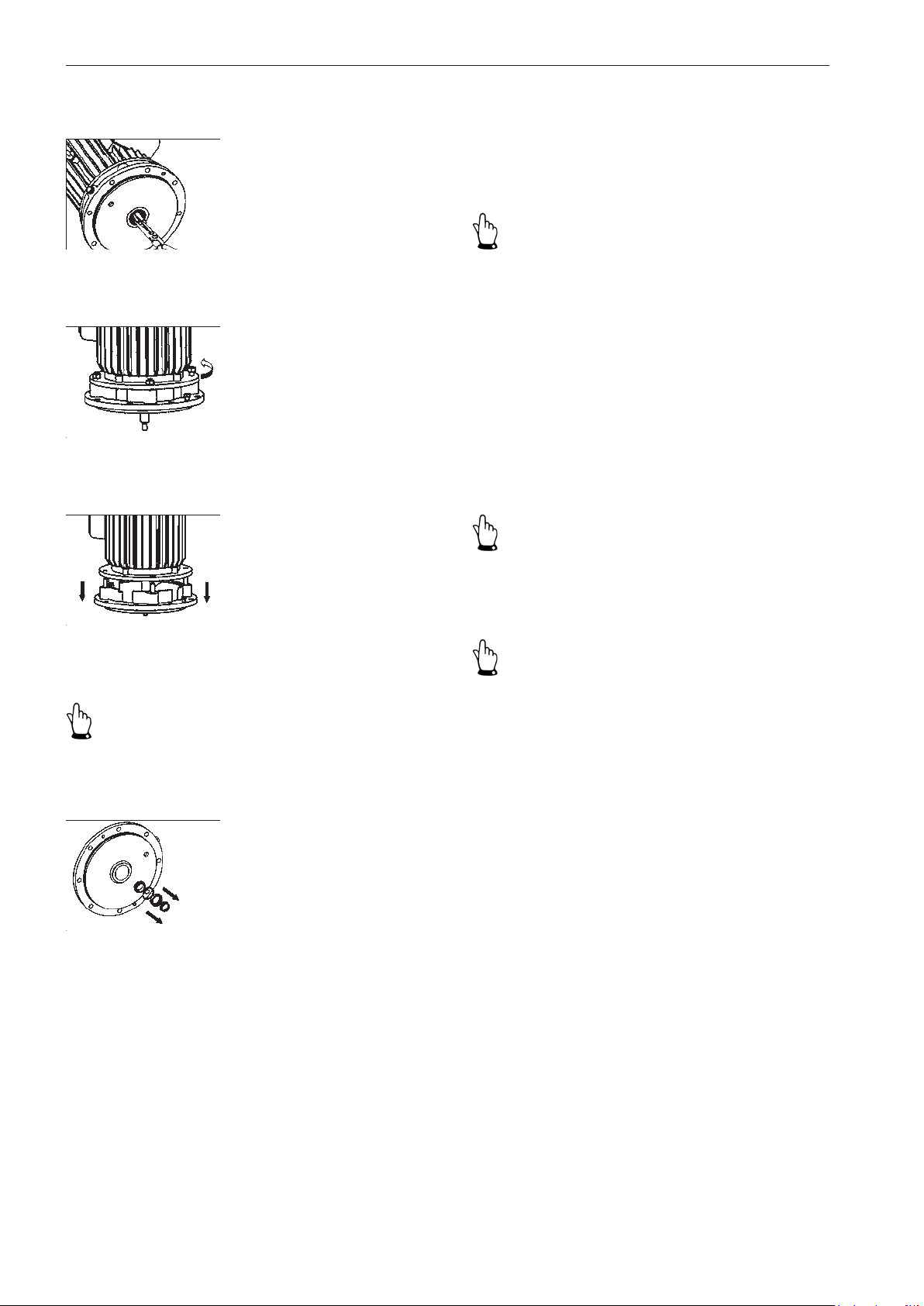
Disassembly / assembly
7.
Remove the key (940) from
the keyseat.
8.
Loosen the connecting bolts
from the block motor (802)
and intermediate casing
(113).
9.
Pull the intermediate casing
(113) over the motor shaft
(819).
11.
Clean the chrome-nickel steel motor shaft of any residue
and sediment deposits using fine emery cloth.
Clean any deposits from the seating for the O-ring.
Important!
Replace any seals that are removed. This ensures precise
sealing.
9.2 Assembly
Before starting to reassemble the pump all of the dismantled
parts are to be
- checked for signs of damage and wear,
- cleaned and
- replaced with original spare parts if necessary.
Important!
Nuts (920) with a self-locking plastic ring are to be replaced
when reattaching the impeller.
10.
Notice!
A damaged fitting surface does not guarantee a precise
seal.
Do not damage the seating for the O-ring.
Remove all components of
the mechanical seal (433)
from the intermediate casing
(113).
Important!
To reduce friction during assembly lubricate all sliding
surfaces of the elastomers with low surface tension water
(added detergent).
Warning - do not use oil or grease!
52
Page 53
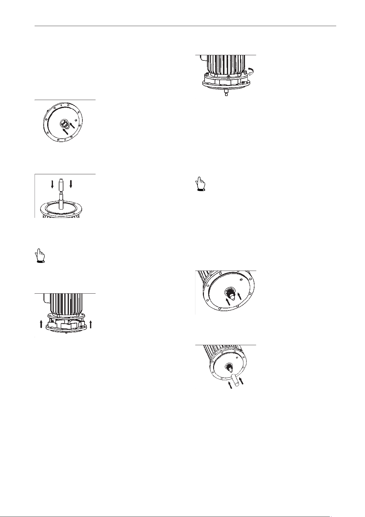
Disassembly / assembly
1.
When inserting the pressure-sensitive counter ring ensure
- an even distribution of pressure,
- you use a clean pin with a soft seating and
- that no foreign particles are located on the sliding surfaces.
Insert the counter ring with
the O-ring into the intermediate casing (113) by hand.
2.
Slide assembly aids (accessories) onto the motor shaft
(819) (if available).
4.
Screw the intermediate casing (113) to the block motor
(802).
Installation of the mechanical seal
Various mechanical seals are used depending on the version of pump:
• Mechanical seal with bellows ⇒ (5.1.1 - 5.1.2)
• Mechanical seal with conical spring ⇒ (5.2.1 - 5.2.2)
Important!
- Make sure you degrease the shaft surface!
- The pretension of the spring is obtained through the installation of the impeller.
3.
Important!
Do not damage the counter ring of the mechanical seal on
the thread and change-over of the motor shaft or press at
an angle!
Carefully slide the intermediate casing (113) over the
motor shaft (819) and onto
the centering of the block
motor (802).
Installation of mechanical seal with bellows
(5.1.1-5.1.2)
5.1.1
Carefully slide the rotating
sliding ring with bellows and
spring over the motor shaft
shoulder and up to the integrated counter ring using a
screwing motion.
5.1.2
Use assembly aids (accessories) (if available) to ensure
an optimal seating of the
mechanical seal on the motor
shaft (819).
⇒ 6.
53
Page 54
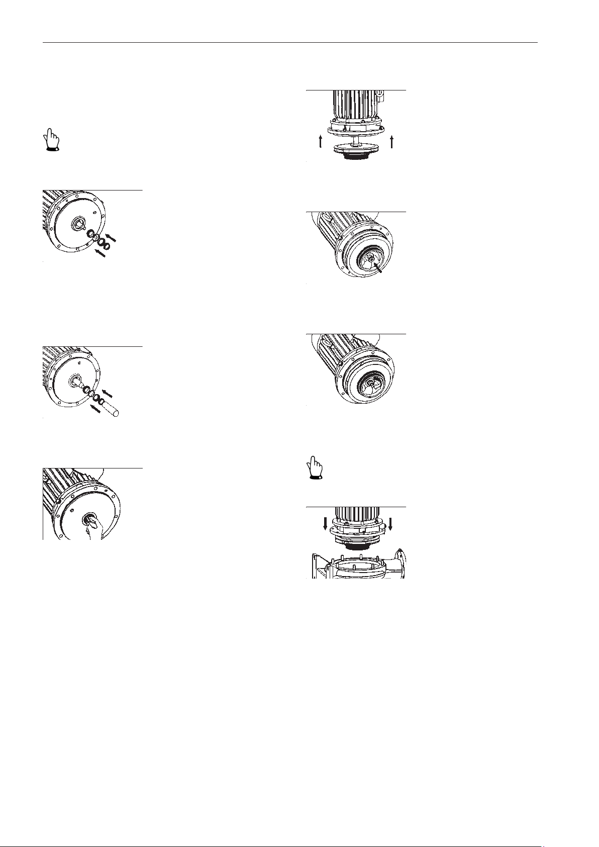
Disassembly / assembly
Installation of mechanical seal with conical spring
(5.2.1-5.2.2)
5.2.1
Important!
Insert the pin on the conical spring into the groove of the
rotating sliding ring.
Slide the components of the
mechanical seal over the motor shaft shoulder and up to
the integrated counter ring in
the following order:
- Rotating sliding ring
- O-ring
- Disc
- Conical spring
5.2.2
Slide the individual components up to the integrated
counter ring using assembly
aids (accessories) (if available).
7.
Slide the impeller (230) onto
the motor shaft (819).
8.
Slide the washer (554) onto
the motor shaft (819).
9.
Tighten the nut (920).
10.
6.
Important!
Insert the key (940) into the
motor shaft groove.
Turn back jack screws beforehand.
Place the gasket (400/400.1)
or O-ring (412) between the
pump casing (101) and the
intermediate casing (113).
Then insert the complete
interchangeable module into
the centering of the pump
casing.
54
Page 55
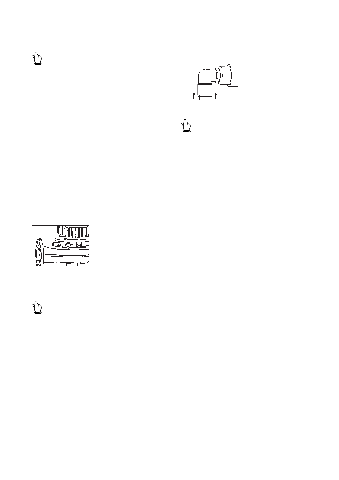
Disassembly / assembly
11.
Important!
- Too large an air gap results in significant performance
reduction of the pump.
- The air gap setting is not applicable for closed multi vane
impellers.
Air gap setting for open multi vane impellers:
- Air gap between the front side of the blade and mating
surface of the pump casing: 0.3 - 0.5 mm.
- Check with a depth gauge
1.) Impeller gap too narrow:
Place a second gasket (400/400.1) between the pump casing
(101) and intermediate casing (113) if the impeller (230) runs
in the opposite direction on the pump casing (101).
2.) Impeller gap too wide:
Place a shim behind the impeller (230) to compensate the
air gap.
Secure the cooling pipes to the pump casing (101) and
intermediate casing (113) in the following manner:
Press the pressure ring backwards. Then insert the hose
in the right angle connector.
Then release the pressure
ring.
Important!
In the case of the design with the base rail, screw together
the block motor (802) and rail (593).
- Check the free run of the impeller (230) by turning it!
- Establish the electrical connection of the block motor (see
section 5.4 'Electrical connection')!
• Observe the connection type (refer to the name plate
on the motor)
• Observe the "right-hand" direction of rotation (see sec-
tion 5.6 'Direction of rotation check')
12.
Screw the pump casing (101)
to the intermediate casing
(113).
Cooling hose mounting for UNIBLOCK-GFC:
Important!
- Shorten the hoses at both ends by approximately 5 mm.
This ensures precise sealing.
- Re-close the ball valve (006) after assembly.
Start up the pump unit (see section 6 'Commissioning').
55
 Loading...