

Page 1
Please read this original user manual before using this gate for the fir st time! Act
User Manual
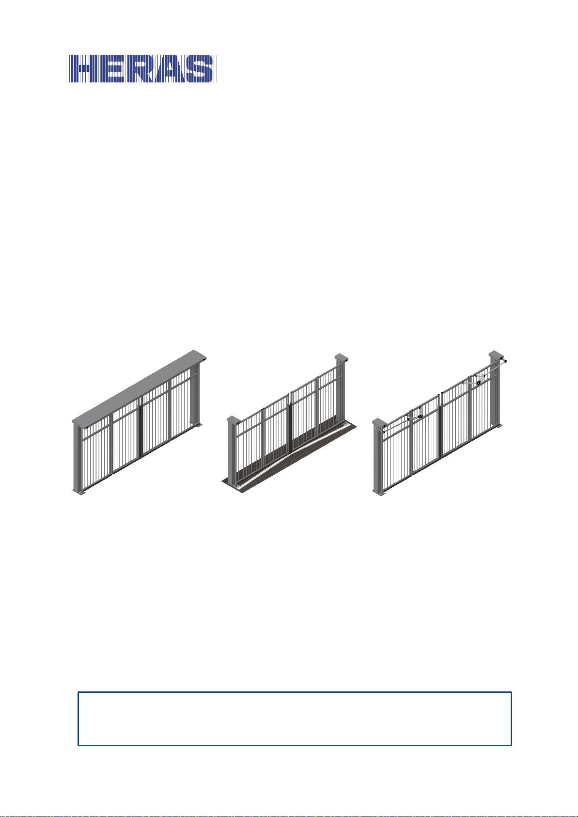
sGate top guided
sGate bottom guided
sGate trackless
in accordance with the manual and keep it in a safe place for later use or for the
following owner.
EN – Translation of the original user manual - 3.0 | 2018
Page 2

2
EN – Translation of the original user manual - 3.0 | 2018
Page 3

3
CONTENTS
FOREWORD ............................................................................................................ 5
PREFACE .......................................................................................................... 6 1
1.1 MANUFACTURER / SUPPLIER ........................................................................... 6
1.2 SERVICE / MAINTENANCE .............................................................................. 6
1.3 DEFINITIONS: USER / OPERATOR / ENGINEER .................................................. 6
1.4 PRESCRIBED USE / APPLICATION .................................................................... 7
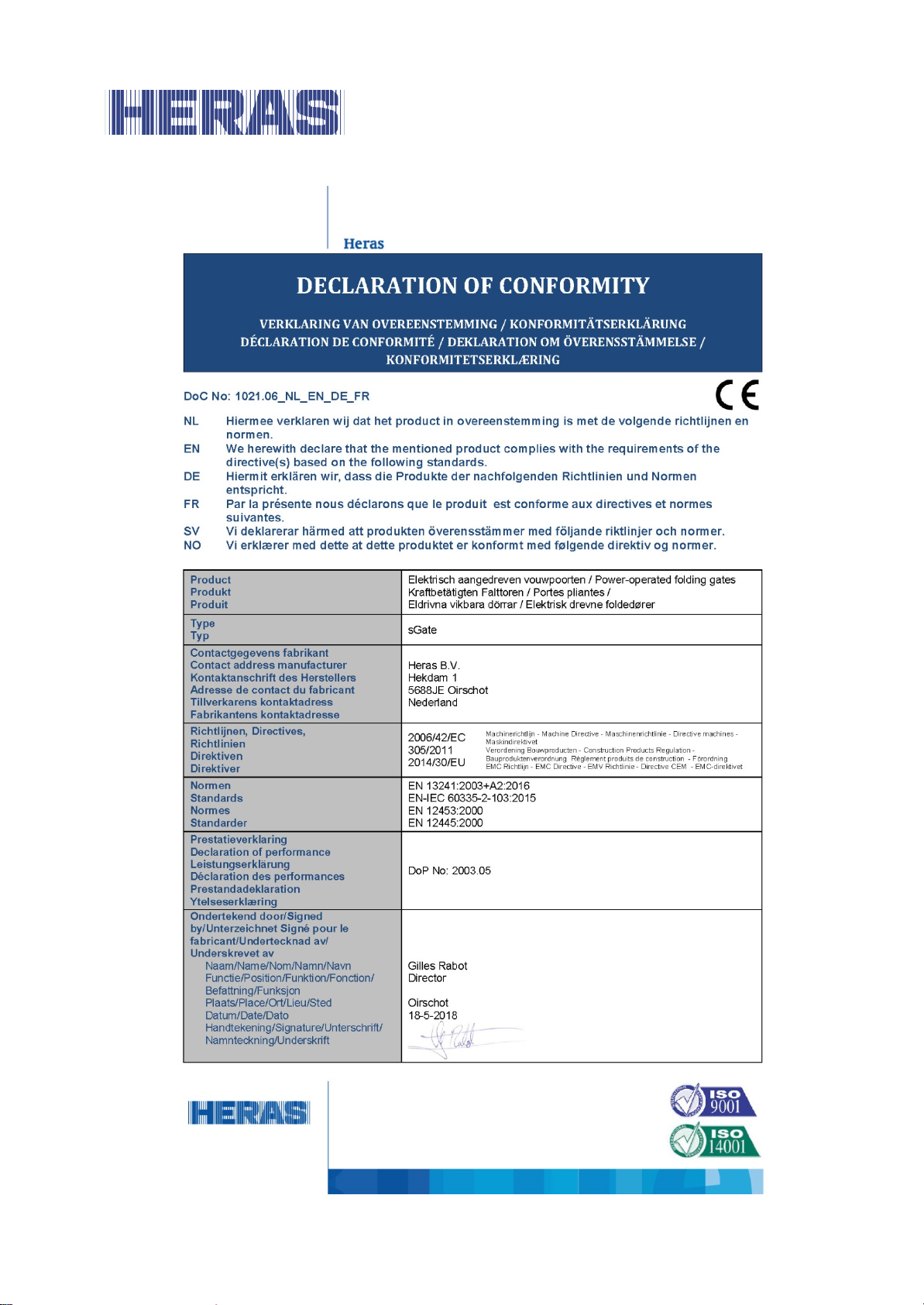
1.5 CONFORMITY WITH EUROPEAN DIRECTIVES ..................................................... 7
1.6 DELIVERY .................................................................................................... 7
1.7 GENERAL INFORMATION REGARDING THE ELECTRICAL CONNECTIONS ................ 8
1.8 DELIVERY OF DRIVE UNIT .............................................................................. 8
SAFETY ............................................................................................................. 8 2
EXPLANATION OF THE SYMBOLS ..................................................................... 8
2.1
2.2 SAFETY DISTANCES ...................................................................................... 9
2.3 GENERAL SAFETY INSTRUCTIONS ................................................................... 9
2.4 SAFETY PROVISIONS EMPLOYED ................................................................... 10
2.5 INTENDED USE ........................................................................................... 10
2.6 SAFETY DURING USE ................................................................................... 10
2.7 SAFETY DURING INSTALLATION, MAINTENANCE AND DISASSEMBLY ................. 11
OPERATION .................................................................................................... 12 3
OPENING/CLOSING GATE - NORMAL USE ....................................................... 12
3.1
3.2 OPEN /CLOSE MANUALLY ............................................................................. 12
3.2.1 Unlock the motor/gate ........................................................................... 12
Connect the motor/gate ......................................................................... 12 3.2.1
DESCRIPTION ................................................................................................ 14 4
4.1
SGATE TOP GUIDED .................................................................................... 14
4.2 SGATE BOTTOM GUIDED .............................................................................. 15
4.3 SGATE TRACKLESS ...................................................................................... 16
4.4 SAFETY EDGES ........................................................................................... 16
4.5 PHOTOCELLS .............................................................................................. 17
4.6 LOOP DETECTION ....................................................................................... 17
4.7 TRAFFIC LIGHTS ......................................................................................... 17
FAULTS ........................................................................................................... 18 5
5.1 DEFECTIVE PHOTOCELL OR SAFETY EDGE ...................................................... 18
EMERGENCY STOP .......................................................................................... 18 6
MAINTENAN CE INS T RUCTIONS ...................................................................... 18 7
GATE MAINTENANCE ................................................................................... 18
7.1
7.2 CLEANING .................................................................................................. 19
EN – Translation of the original user manual - 3.0 | 2018
Page 4

4
DECOMMISSIO NING AND REMOVAL ............................................................... 19 8
SPARE PARTS ................................................................................................. 20 9
TECHNICAL DATA ........................................................................................ 20 10
10.1 GATE DESCRIPTION ................................................................................. 20
10.2 DRIVE DESCRIPTION ................................................................................ 20
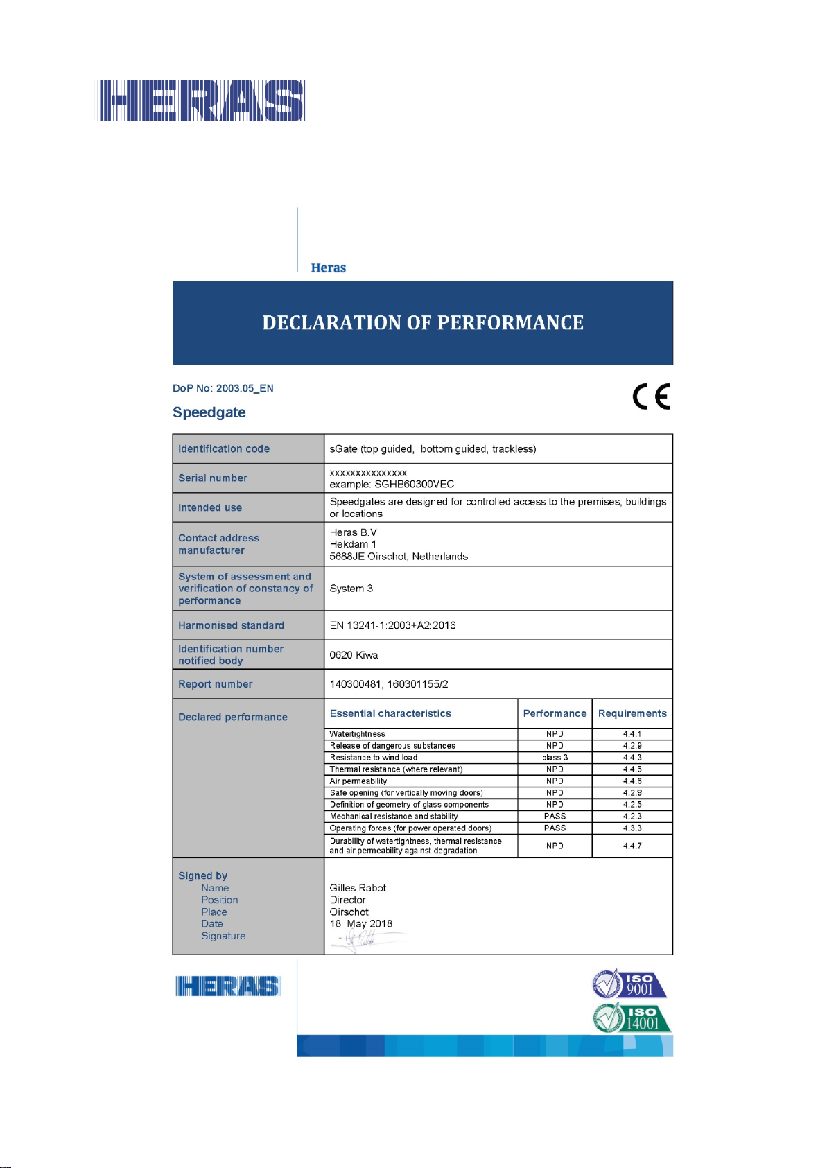
APPENDIX A: DECLARATIONS DOP / DOC ............................................................ 22
APPENDIX B: OVERVIEW OF ERROR MESSAGES .................................................. 24
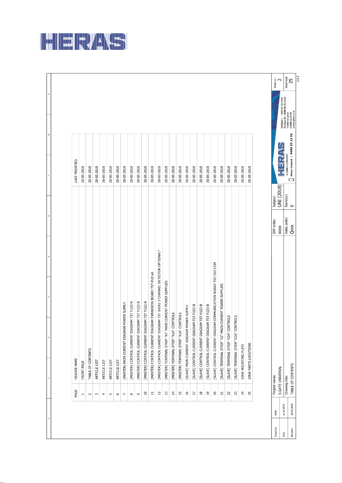
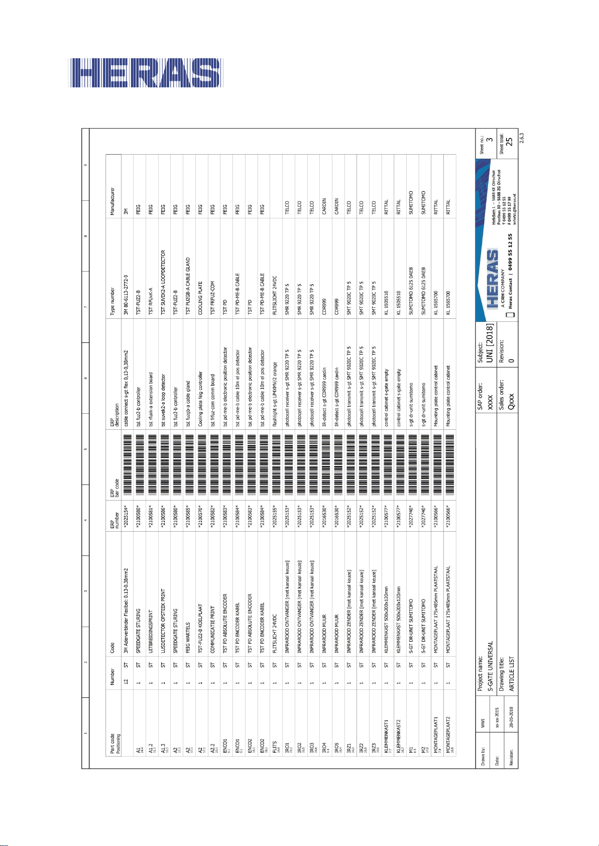
APPENDIX C: ELECTRIC DIAGRAM SGATE UNIVERSAL ......................................... 27
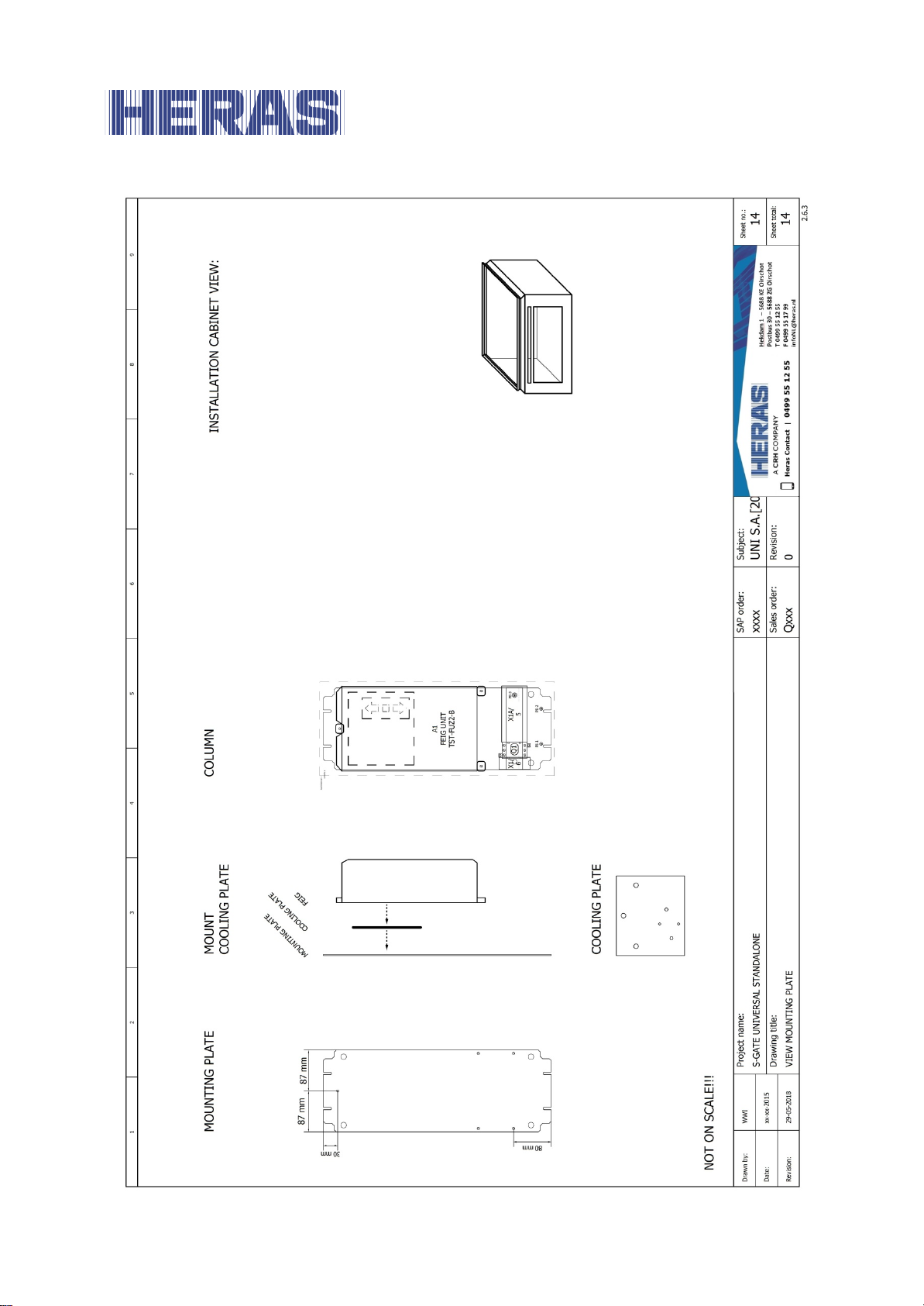
APPENDIX D: ELECTRIC DIAGRAM SGATE UNIVERSAL STANDALONE ................... 52
EN – Translation of the original user manual - 3.0 | 2018
Page 5

5
FOREWORD
This manual enables you to operate and maintain the gate correctly. Possible options are briefly described. The Operation chapter explains the control unit. Among
other things, it describes how you can change various settings. The Maintenance
chapter is extremely important to ensure that you can continue to operate your
gate problem free in the long term.
Please read this user manual carefully before using the gate.
Store the manual in a safe place to be able to refer to it later if required. This de-
scription is intended for the operator of the gate. The installer uses a separate
manual to assemble and install the gate.
The installer uses an installation scheme for the drive concerned and works according to the applicable standards. In the event of a fault, you should contact a Heras
certified technician.
EN – Translation of the original user manual - 3.0 | 2018
Page 6

6
Heras Netherlands
Telephone
+31(0) 499 551 255
Heras Germany
Telephone
+49 (0)1805 437277
Heras England
Telephone
+44(0) 1302 364 551
Heras France
Telephone
+33(0) 3 88 067 000
Heras Norway
Telephone
+47(-) 22 900 555
Heras Sweden
Telephone
+46(0) 77 1506050
PREFACE 1
1.1 MANUFACTURER / SUPPLIER
Manufacturer:
Hekdam 1, 5688 JE Oirschot
Netherlands
Tel.: +31(0)499 -551225
www.heras.com
Technical Construction File: Heras B.V. manager, T&I Department
1.2 SERVICE / MAINTENANCE
In the event of problems, failures or q uestions you can contact:
Heras B.V.
1.3 DEFINITIONS: USER / OPERATOR / ENGINEER
User: Anyone using the gate.
Operator: A user who is familiar with all safety aspects dealt with in this manual.
Operators are not allowed to carry out any installation work on the
gate unless explicitly specified.
Engineer: The engineer is a Heras fitter (or an engineer employed by the cus-
tomer who has been given explicit permission in writing from Heras)
who is qualified to perform technical interventions on the gate.
EN – Translation of the original user manual - 3.0 | 2018
Page 7
7
2006/42/
EC
Machine Directive
2014/30
EU
EMC Directive (electromagnetic compati305/2011
EC
Construction Product Regulation
1.4 PRESCRIBED USE / APPLICATION
Only the correct installation and maintenance by an authorised/qualified company
or person in agreement with the user manual, logbook, checklists and maintenance
lists can ensure the safe operation of the system.
A qualified person is, according to EN 12635, a person who has the required training, qualified
knowledge and practical experience required to install, test and maintain a gate
system correctly and safely.
1.5 CONFORMITY WITH EUROPEAN DIRECTIVES
The installation complies with the following EU Directives/ regulations:
bility)
The design and production has been executed compli ant wi th the appl icabl e product
standard EN 13241 and the underlying standards EN 12604, EN 12453, EN 12978
and 12635.
A Declaration of Performance (DoP) and Decl aration of C onformity (DoC) are obli gatory for this product. The DoP and DoC ar e included i n Appendix A.
The CE mark is located on the left column of the g ate.
1.6 DELIVERY
The gate and the gate drive and control unit must be installed, connected, set up
and tuned by a fitter or an engineer who also connects and programs any accessories. The gate control unit is adjusted to the options/accessories agreed with the
user. The relevant options ar e laid down during han d-over.
Of course, you can add optional/accessories afterwards. Contact your supplier for
this.
Gates are always delivered fully tested.
EN – Translation of the original user manual - 3.0 | 2018
Page 8

8
1.7 GENERAL INFORMATION REGARDING THE ELECTRICAL CONNECTIONS
Electrical connections must be made compliant with the supplied wiring diagram.
It is important that the system is correctly earthed (Protective grounding in accordance with DIN VDE).
Because EMC-related suppression components can leak current to the earth cable,
it is advisable that you do not protect the control unit with a Residual Current Device. When switching on the system, a high starting current can be generated due
to the charging of the intermediate circuit.
If after measurement during commissioning it appears that the leakage current exceeds the permitted 3.5 mA, an additional grounding, in accordance with EN
60335-1 and IEC 30364-5-54, must be provided. Measurement is made according
to EN 60335-2-103. Consult your installer for this.
Take into account good shielding, for example an automatic circuit breaker 16A B
characteristic.
Ensure that the feeder cables are not carrying power during commissioning.
1.8 DELIVERY OF DRIVE UNIT
After installation and commissioning, by a Heras technician or a technician
trained by Heras, the cover of the drive unit must be closed. This is done to
prevent unauthorised access.
SAFETY 2
2.1 EXPLANATION OF THE SYMBOLS
Caution: To prevent personal injury, you must observe the safety in-
structions below.
Note: To prevent material damage, you must observe the safety in-
structions below.
EN – Translation of the original user manual - 3.0 | 2018
Page 9
9
Information: This is followed by further information or by a reference to other
documents.
Warning: Risk of limbs getting crushed
2.2 SAFETY DISTANCES
Safety distances apply for the area into which the gate slides in accordance with
EN 12445 4.1.1.1 for electrically driven gates.
2.3 GENERAL SAFETY INSTRUCTIONS
• The operator must read the entire user manual before the gate is used for
the first time. The instructions stated in the user manual must be observed
and complied with. All other forms of use can cause unexpected hazards and
are forbidden.
• It is forbidden to apply the drive unit to gates other than those stated in this
manual, without Heras' permission.
• Applying a third-party drive unit and/or safety edge may affect safety and
will invalidate the CE mark.
• The gate must only be put into use if all safety facilities are in place and
connected, and work properly.
• All faults which might present a source of danger to the user or to third per-
sons must be eliminated immediately.
• All warnings and safety notices on the equipment must be in place and clear-
ly legible at all times.
• Closing the gate infill openings in any way, such as by means of banners,
advertising signs etc, is not allowed as this may negatively affect the safe
operation of the gate.
• All alterations or extensions to the gate must be carried out by qualified per-
sonnel using parts which the manufacturer has defined as suitable for such
alterations or extensions. Any failure to comply with these instructions will
be considered as non-compliant behavior and will invalidate the manufacturer's guarantee, as a result of which the risk entirely transfers to the user.
• Improper usage or servicing or ignoring the operating instructions can be a
source of danger for persons, and/or result in material damage.
• If the meaning of any part of these installation and operating instructions is
not clear, then please contact your supplier before you use the equipment.
• This manual must always be available at the operating location of the drive
EN – Translation of the original user manual - 3.0 | 2018
Page 10
10
unit/gate. This manual must be thoroughly read and applied by all persons
who are in charge of operating, maintaining and repairing the drive unit.
2.4 SAFETY PROVISIONS EMPLOYED
• To protect people and goods from injury or damage, the gate is fitted with
safety provisions including safety edges and/or photocells.
These serve as emergency provisions that immediately stop and reverse the
movement of the gate. It is forbidden to use these provisions to stop the
gate normally.
• For a gate with hold-to-run control, the above-mentioned safety provisions
are not necessary and will therefore not be standard provisions.
With this type of operation, the gate stops immediately as soon as the switch
is released.
2.5 INTENDED USE
The gate is intended to control access to a specific plot, premises or site. The gate
is intended for both industrial and private use.
The gate drive and control unit is adjusted to the options agreed with the
user. The relevant options are laid down during hand-over.
Carefully read this user manual before operating the gate. You must always be familiar with the operating mode the gate is in.
2.6 SAFETY DURING USE
Children or people with a disability must not operate the gate. Parents must
s supervise their children to prevent them playing with the gate.
PARENTS ARE RESPONSIBLE FOR THEIR CHILDREN
• Keep a safe distance from the moving gate. Warning icons to this effect
have been installed in various locations
• Only pass through the gate when it is completely open.
• The gate must not be operated in windy conditions, wind force ≥9 Beau-
fort. The gate leaf can swing in a way that can result in damage to the
construction.
• The safety edges serve as emergency facilities to immediately stop and
EN – Translation of the original user manual - 3.0 | 2018
.
Page 11

11
reverse the gate movement. Using them as a regular gate stop feature is
not allowed. Since the head stiles of the gate have safety edges that cannot cover their full height, there is still some risk of people getting
trapped by the gate here.
• When hold-to-run-control is employed, the gate must only be operated if
it can be seen completely, directly and in real-time. Operation must be
via a permanently installed operating device, for instance a key switch or
push button. This operating device must be located in such a way that the
operator's position is safe. The gate must stop immediately when the button or key is released. Other operating devices are not allowed.
• The gate must be able to move freely without there being obstacles in the
gate opening passage or anywhere else on the moving trajectory of t h e
gate. Do not stick any objects through, over or under the gate which
might block the gate.
• The guide rail of the gate must always be free of snow, ice or contami-
nants that may affect the sliding behaviour. In the event of frost, check
this before commissioning the gate. If the running surface is blocked, the
gate will not move at all or will not complete its movement. An irregular
running surface may cause damage to the drive and/or road wheels.
• Climbing the gate is strictly forbidden as people climbing the gate could
be hurt if the gate is started unexpectedly.
• Always close the access doors during use.
2.7 SAFETY DURING INSTALLATION, MAINTENANCE AND DISASSEMBLY
• When work is carried out or while cleaning the gate, the power supply to
the system must be switched off and it must be ensured that it cannot be
switched on unexpectedly.
• To move the gate manually, first switch the automatic fuse in the drive
unit cabinet to “off” and make sure it cannot be switched on again (e.g.
by locking the cabinet).
• The EN 12453 standard must be taken into consideration during installa-
tion and maintenance. To achieve a good safety level, the above standard and the national regulations must be taken into account in non-EC
countries.
EN – Translation of the original user manual - 3.0 | 2018
Page 12
12
OPERATION 3
3.1 OPENING/CLOSING GATE - NORMAL USE
The gate can be operated using pulse operation, for instance via a button or key
switch. The locati on of the operating device d epends on the customer 's c h oice or
the operating mode.
OPEN:
Press the “Open” button. The gate slides open to the next end position. This
can be completely or partially open (if the “Partially
open” function has been programmed).
CLOSE:
Press the "Close" button.
The gate closes completely.
STOP:
Press the "Stop" button.
The gate will stop immediately, irrespective of its
direction of travel. To restart the gate press “Open”
or "Close".
3.2 OPEN /CLOSE MANUALLY
In emergencies or power outages, the gate can also be disconnected from the drive
unit. This requires the column to be opened. The actions described below must be
performed in both
columns.
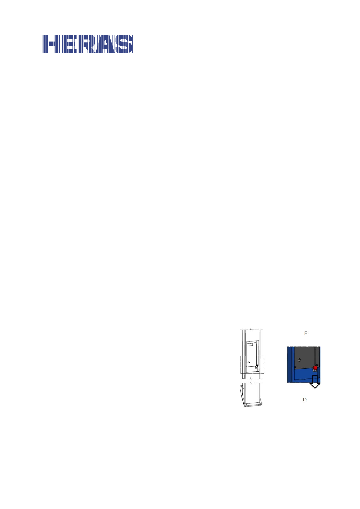
3.2.1 Unlock the motor/gate
• Unlock the bottom cover.
• Remove the cover.
• Pull the cord down and hang it in the bracket.
The motor brake is released and the gate can be
operated manually.
• Close the cover again.
Connect the motor/ga te 3.2.1
• Unlock the bottom cover.
• Remove the cover.
EN – Translation of the original user manual - 3.0 | 2018
Figure 1: disconnecting the motor
Page 13

13
• Remove the cord from the bracket and release it.
The motor brake is connected again and locks the gate.
• Close the cover again. The gate can once again be operated electrically.
EN – Translation of the original user manual - 3.0 | 2018
Page 14
14
Traffic light
Drive unit
Safety edge
Gate control
Safety edge
Top guide rails
Bars
DESCRIPTION 4
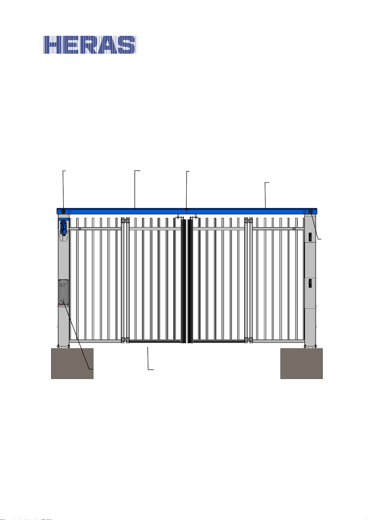
4.1 SGATE TOP GUIDED
The sGate with top guide rails is a gate with a modular structure for passages with
a width of approx. 6 meters wide and a headroom of up to approx. 4 meters.
Applications include port areas, company buildings, office buildings, storage sites,
garden and landscape areas, high-risk sites, airports, transport and distribution
sites, and parking garages.
Figure 2: sGate top guided terms
EN – Translation of the original user manual - 3.0 | 2018
Page 15
15
Drive unit
Bars
Safety edge
Traffic light
Gate control
Safety edge
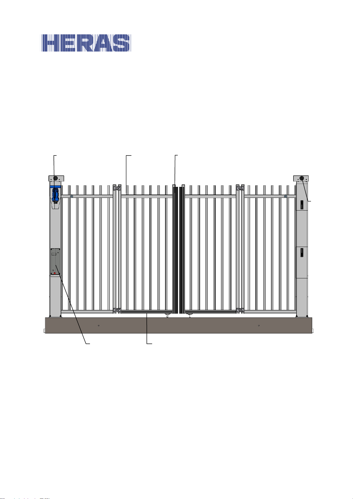
4.2 SGATE BOTTOM GUIDED
The sGate with bottom guide rails is a factory-built gate for passages with a width
of up to approx. 6 meters.
Applications include port areas, company buildings, office buildings, storage sites,
garden and landscape areas, high-risk sites, airports, transport and distribution
sites, and parking garages.
Figure 3: sGate bottom guided terms
EN – Translation of the original user manual - 3.0 | 2018
Page 16
16
Drive unit
Bars
Safety edge
Gate control
Foundation
Rod drive
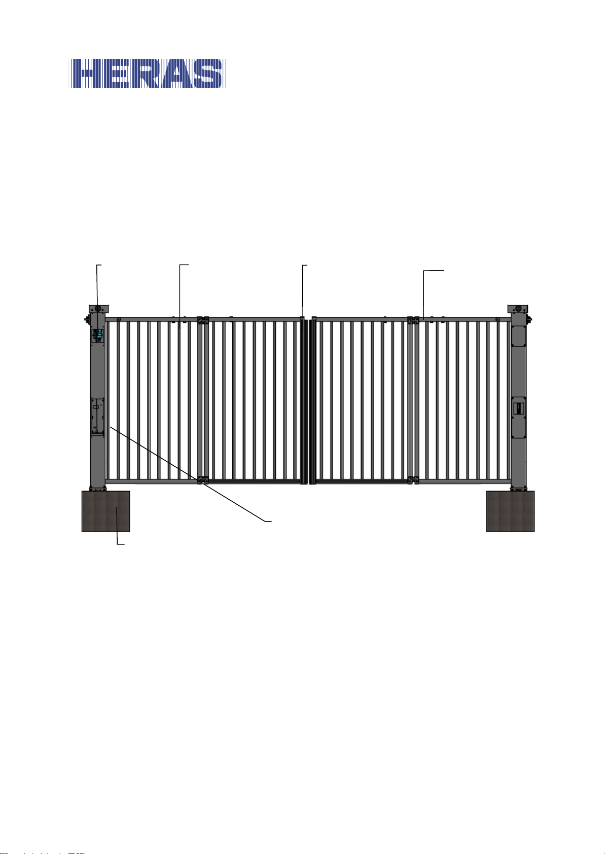
4.3 SGATE TRACKLESS
The sGate with rod drive is a gate with a modular structure for passages with a
width of approx. 8 meters wide.
Applications include port areas, company buildings, office buildings, storage sites,
garden and landscape areas, high-risk sites, airports, transport and distribution
sites, and parking garages.
Figure 4: sGate Trackless terms
4.4 SAFETY EDGES
Power operated Heras gates are protected by safety edges. The type of device and
the speed of movement depend on the mot or con trol unit used. If th e s a f ety device
touches an obstacle, the gate will immediately stop and reverse. Dependent on the
device, the gate will restart. The safety edges have been fitted to the stationary
and/or moving part or parts of the gate. They are not required for hold-to-runcontrol. These strips serve as safety components.
Before the gate is moved, the control system checks the status of the safety edges.
If one of the safety edges is faulty, the gate can only be opened and closed in holdto-run-mode. In that case, consult a qualified engineer.
EN – Translation of the original user manual - 3.0 | 2018
Page 17

17
See the chapter 1.2 “SERVICE /MAINTENANCE”
4.5 PHOTOCELLS
Photocells detect whether there are obstacles in the path taken by the gate. If an
obstacle is detected during the closing movement, the gate will stop immediately.
The photocell is active during closing and partly during opening of the gate.
Gates can be fitted with multiple photocells.
4.6 LOOP DETECTION
The detection loops are designed to detect vehicles. The opening movement will
be stopped by the control when the trapezoidal loop, which lies on the side where
the leafs rotate, is energised. If you are on top of this loop while the gate is
closed, it will not open. When the loop is released, the gate will (continue to)
open.
The closing movement will be stopped by the control when the trapezoidal loop
is energised. When the loop is released again, the gate will close further.
The opening movem en t wil l have no influence on t h e movement when th e rectangular loop, which lies on the other side, is energised. The closing movement will be
stopped by the control when the rectangular loop is energised. When the loop is
released the gate will close further.
4.7 TRAFFIC LIGHTS
The gate can be equipped with traffic lights on both sides. These are clearly visible
on the top of columns. The traffic lights indicate a red cross or green arrow with
which priority can be given to each direction.
Depending on the chosen operation, a green arrow will light up on one side while a
red cross lights up on the other side. It is also possible that both directions get a
green arrow, for example, when using the pedestrian passage.
EN – Translation of the original user manual - 3.0 | 2018
Page 18
18
FAULTS 5
5.1 DEFECTIVE PHOTOCELL OR SAFETY EDGE
If a photocell or safety device is defective, the gate can only be opened and closed
using the hold-to-run switch. In this case, consult a qualified technician.
See chapter “SERVICE / MAINTENANCE”
EMERGENCY STOP 6
The gate is not equipped with an emergency stop system. According to the Machine
Directive 2006/42/EC, annex 1, article 1.2.4.3., this is not necessary if the emergency stop system would not lower the risk. However, an emergency stop system
can be connected to the control unit. Please refer to the instruction in the installa-
tion manual.
MAINTENANCE INSTRUCTIONS 7
• When working on the gate or cleaning it, the power supply to the system
must be switched off and protected from unauthorized switching on.
• If the gate must be moved manually, first turn the system circuit breaker in
the motor cabinet to the "off" position and protect it from being switched on
(e.g. by locking the cabinet).
7.1 GATE MAINTENANCE
To ensure optimal operation of the gate, maintenance must be performed by a
qualified technician at least once every 6 months or after a previously reached
number of cycles. When maintenance is not, or is incorrectly carried out, our user
EN – Translation of the original user manual - 3.0 | 2018
Page 19

19
manual is not followed or functional faults have arisen as a result of wilful damage,
every form of guarantee lapses.
Depending on the version, we recomm en d the following:
• Bottom guided : 6 months or 25,000 cycles
• Top guided : 6 months or 50,000 cycles
• Trackless : 6 months or 50,000 cycles
During maintenance, essential points of the gate must be periodically checked
based on an inspection protocol:
• Correct operations and adjustment.
• Check all anchor and bolted connections.
• Check for wear of the guide wheels and the running surface/groove
• Check welded joints, damage to coating and zinc
• Check for damage and the operation of detection loops, safety edges and
photocells
7.2 CLEANING
The gate and the outside of the drive unit cabinet can be cleaned using a nonaggressive detergent and a soft cloth, brush or sponge. Avoid using a pressure
cleaner as this might damage the gate and the drive unit.
.
DECOMMISSIONING AND REMOVAL 8
Ensure that the gate is dismantled by a qualified technician.
Disconnect the electricity supply in a safe way from the drive unit.
Use the installation manual.
At the end of their service lives the products must be disposed of in accordance
with all local, regional and national rules and instructions. The guideposts are made
of steel. Heras is also happy to take the products back and then dispose of them in
an appropriate manner.
EN – Translation of the original user manual - 3.0 | 2018
Page 20
20
Clear pass. [m]
4.0 – 6.0
3.0 – 6.0
Height [m]
2.0 – 4.0
2.0 – 2.5
Max. weight [kg]
±550…±1100
±3400 …±6000
Construction
Guide rail at the top
Guide rail at the bottom
Clear pass. [m]
3.0…8.0
Height [m]
2.0…3.0
Max. weight[kg]
±495…±855
Construction
Rod drive
FUZ2B
Supply voltage
1-phase 110..240 VAC ± 10%/ N / PE
Fuse supplied by customer,
max. 16 A
SPARE PAR T S 9
If you have any questions about wear and spare parts, please contact the Service
and Maintenance Service. See Chapter 1.2.
TECHNICAL DATA 10
10.1 GATE DESCRIPTION
Type Top Guided Bottom Guided
Type Trackless
10.2 DRIVE DESCRIPTION
when connected to th e electricity mains
EN – Translation of the original user manual - 3.0 | 2018
Page 21
21
FUZ2B
External power supply for
24 VDC stabilised (±10%) max. 500 mA
Control inputs
24 VDC / typical 15 mA
Relay outputs K1 and K2 1
min. 10mA - max. 230 VAC / 3 A resp. 690 W
Maximum el. motor power
750 W
Housing material
ABS plastic
Dimensions W x H x D
182 x 328 x 102 mm (incl. spacers)
Weight
approx. 5 kilos
IP category of control cabi-
IP54
Operating temperature
-20 °C to +50 °C
Storage temperature range
-20 °C to +70 °C
Relative humidity range
max. 95% non-condensing
24V devices
(fused with a semiconductor fuse that resets
automatically)
< 2 V: inactive -> logical 0
> 10,5 V: active -> logical 1
(galvanically isolated internally)
The functions described in this manual are designed for the prevailing climatic conditions in Europe.
1
If inductive loads are switched (e.g. further relays or brakes), these must be equipped with a
free-wheeling diode as an interference suppression measure
.
EN – Translation of the original user manual - 3.0 | 2018
Page 22
22
Appendix A: Declarations Dop / DoC
EN – Translation of the original user manual - 3.0 | 2018
Page 23
23
EN – Translation of the original user manual - 3.0 | 2018
Page 24

24
P920
Read out fault history
F000
Door open outside p os i-
Parameter value emergency limit switch
F005
Door closed outside posi-
Parameter value emergency limit switch
F020
Running time exceed ed
Current motor has exceeded a set maxi-
F030
Gate runs slowly, the
Axle of the encoder on the motor is loose
F031
Reversal time error at
Wrong direction of rotation
were switched (pulse generators are not
Appendix B: Overview of error messages
tion
Limit switch open range too small
tion
The mechanical bra ke is defective or set
incorrectly
Limit switch open range too small
during opening or closing
or in hold to run mode of
control
change in position is
slower than expected
The mechanical bra ke is defective or set
incorrectly
mum running time
The gate runs with difficulty or is ob-
structed
If mechanical limit switches are used, a
limit switch may be defective
If an encoder is used, this fault is virtually
impossible
Wrong positioning system has been selected.
Motor phase is missing
Motor brake is not released
DES
EN – Translation of the original user manual - 3.0 | 2018
Error recognition setting too small
Movement speed too l ow
Mechanical limit switch remains active or
is defective
In the selection of t h e encoder, an incorrect channel has been selected. A with B
Page 25

25
used)
F067
Safety loop 3 defect
Short circuit or interruption of loop 3
F068
Safety loop 4 def ect
Short circuit or interruption of loop 4
F080
Perform maintenance
Service counter has reached maintenance
F090
Set control parameters
The minimum basic parameters are not
F201
Internal emergency stop
Check the internal emergency stop wiring,
F211
External emergency stop
Check external emergency stop
F212
External emergency stop
Check external emergency stop
F320
Gate blocked during
The gate is stopped during opening
F325
Gate blocked during clo-
The gate is stopped during closing
F360 to
Safety edge 1 is malfunctioning
F370 to
Safety edge 2 is malfunctioning
F400
RAM error
Reset FUE/FUZ
F04B
Communication error
Communication between main print and
F410
Overcurrent limit ((mo-
Motor data set incorrectly
F420
Overcurrent DC link 1
Braking chopper malfunctioning / defect /
erator effect). E.g. when gate is closed
status
set in the control system
F364
F374
active or watchdog active
1
2
opening
sing
test the microprocessor by pressing the
stop sheet, it will display Information
about the possible cause
wiring of 1
wiring of 2
expansion print
tor current or DC link)
EN – Translation of the original user manual - 3.0 | 2018
expansion print is interrupted.
sGate is running too sluggishly
not present
Mains voltage too high
Motor returning too much energy (gen-
Page 26

26
and during a storm.
F430
Temperature too low limit 1
F435
Temperature in the cabinet too low, high
F510
Motor using too much power limit 2
F524
Ext. 24 VDC problem
External 24 VDC fails or is too low/ cloF525
Overvoltage input
Mains voltage is too high or unstable
F530
Low temperature
Temperature of the controls is too low
F535
High temperature
Temperature of the controls is too high
F700
Gate position registration
When using limit switches, both limit
F760
Gate position outside
Incorrect operation of the drive of the po-
F763
DES-B malfunctions
The encoder is mal functioning.
F768
Battery almost empty
The battery current of the TST PD is too
F920
2.5 V malfunction
Hardware defect
F921
15 V malfunction
Hardware defect
F922
Emergency circuit not closed (see connecF931
ROM malfunction
incorrect ROM code / defective hardware
F932
RAM malfunction
Hardware defect
F933
CPU malfunction
the pulse frequen cy to the CPU is not in
sure.
limit 2
error
window range
(ventilate or cool)
switches are activated at the same time
sition sensors
Incorrect operation of the absolute en-
coder of the analysis electronics
Defective hardware or strongly disturbed
environment
low (replace battery)
EN – Translation of the original user manual - 3.0 | 2018
tion terminals)
order
Page 27
27
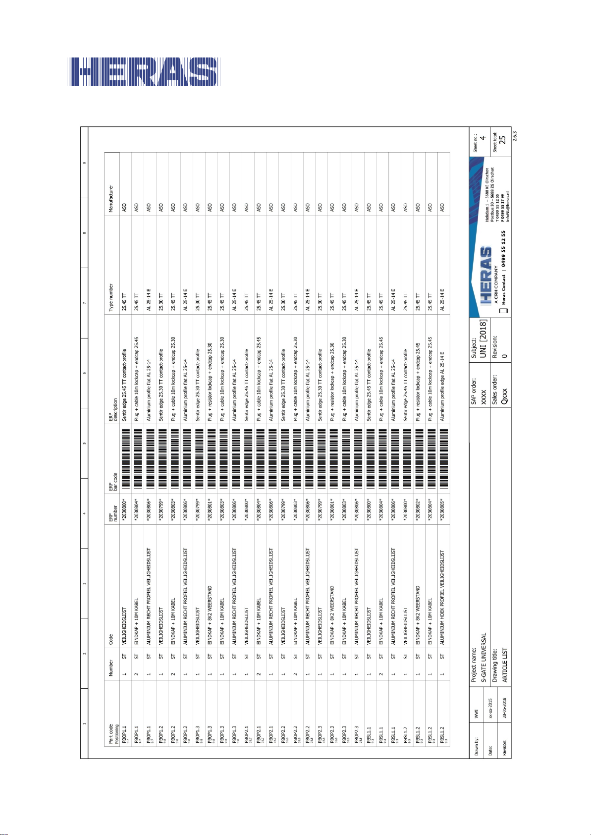
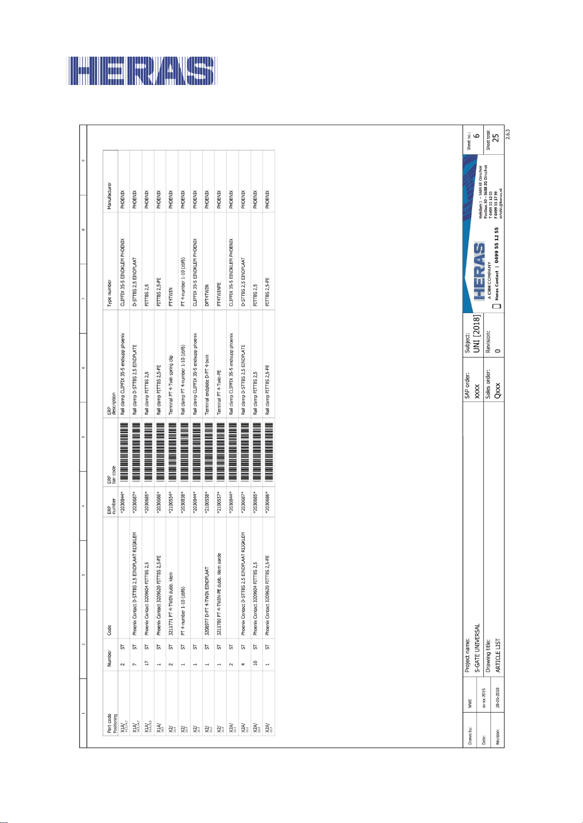
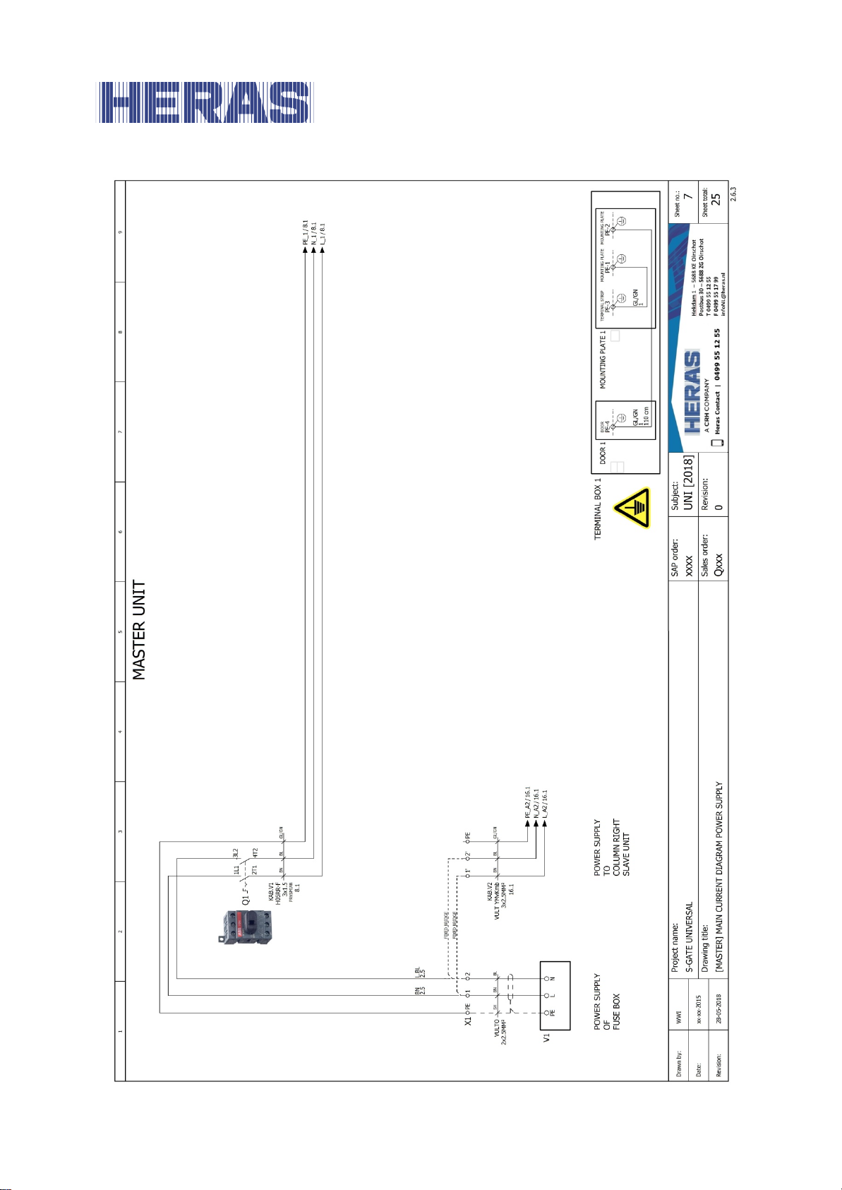
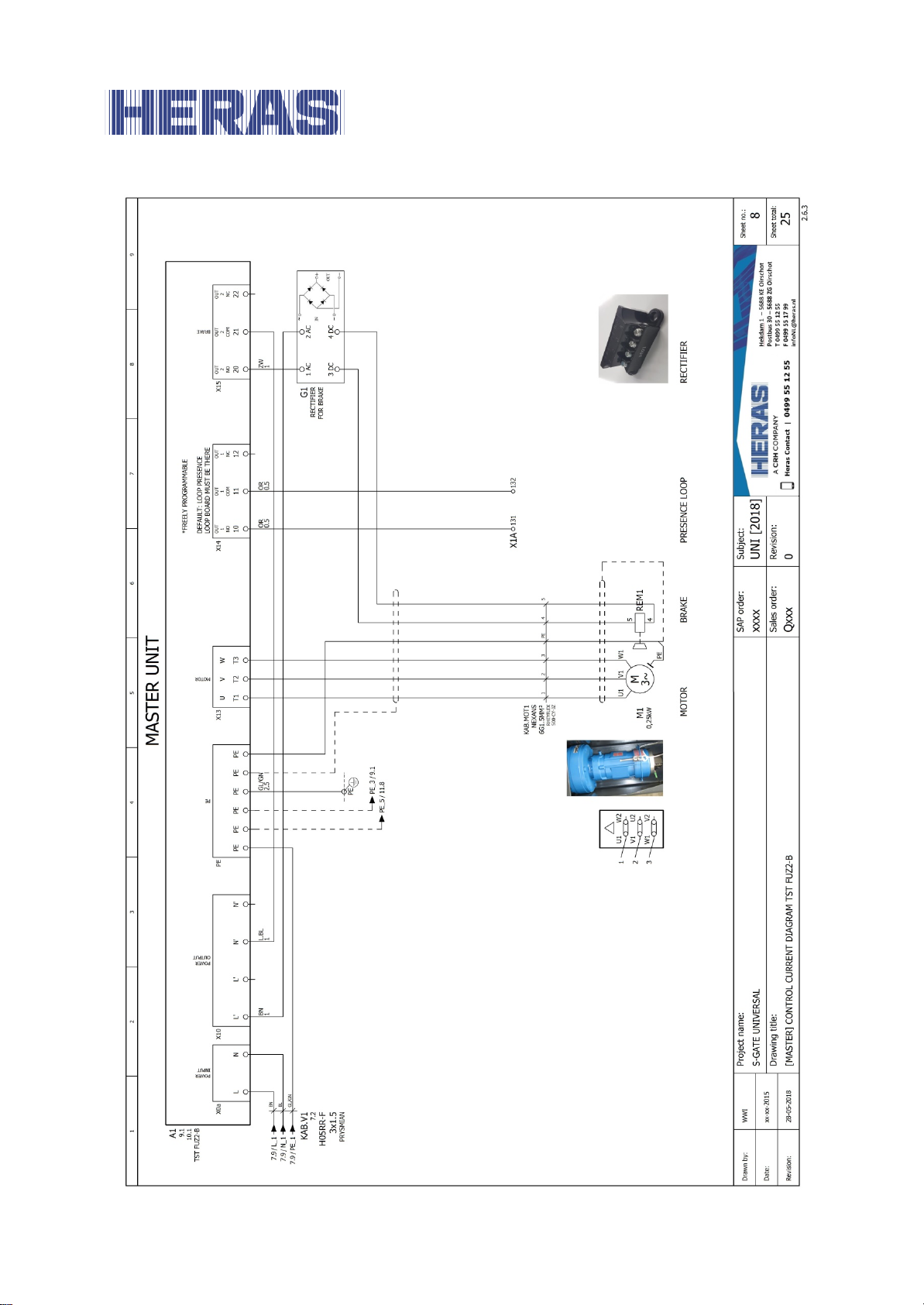
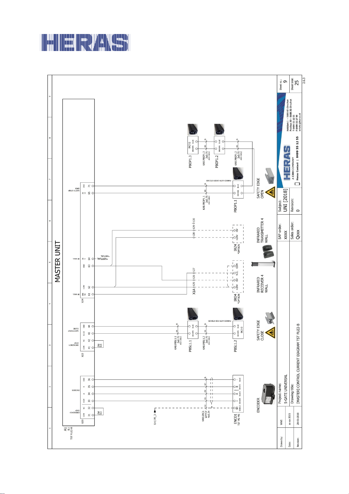
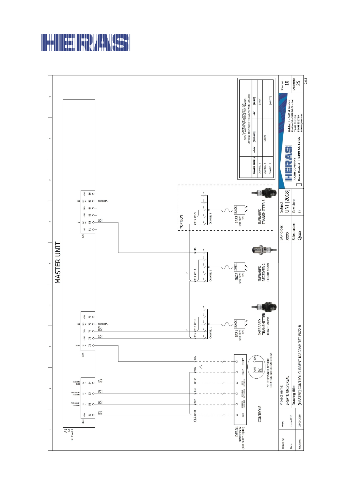
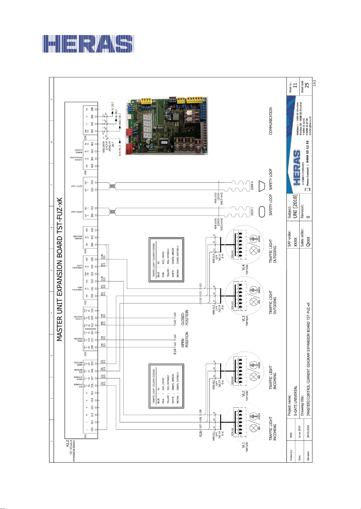
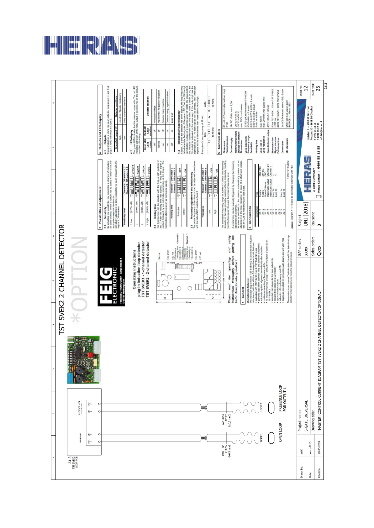
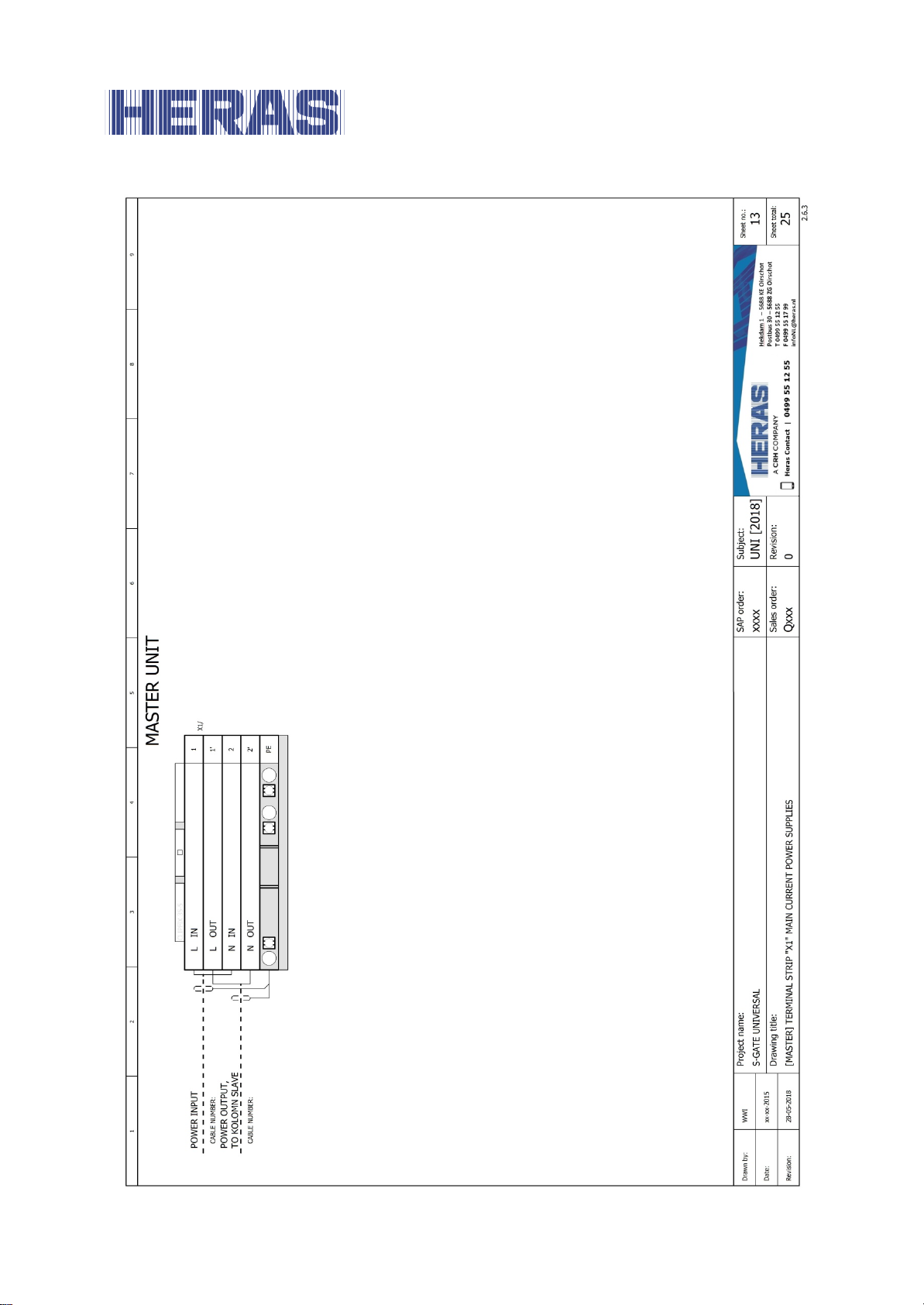
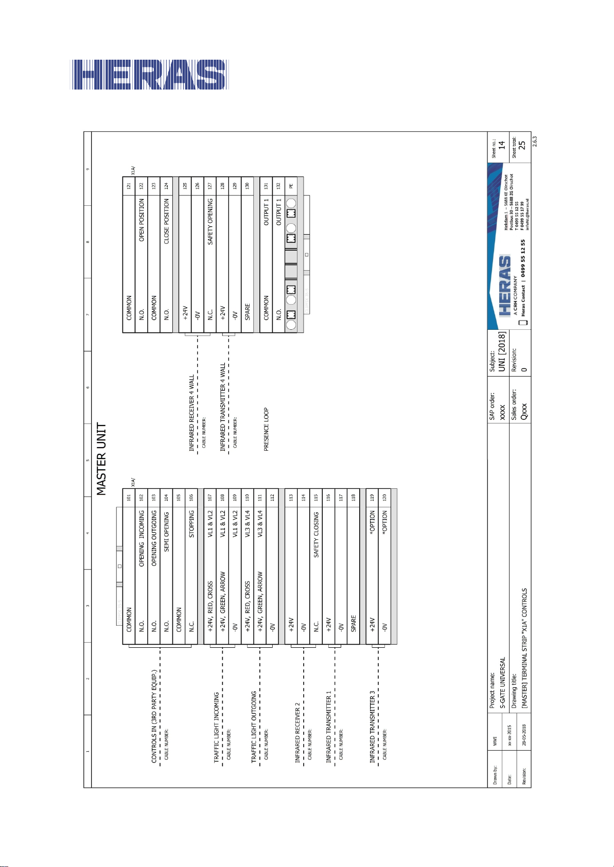
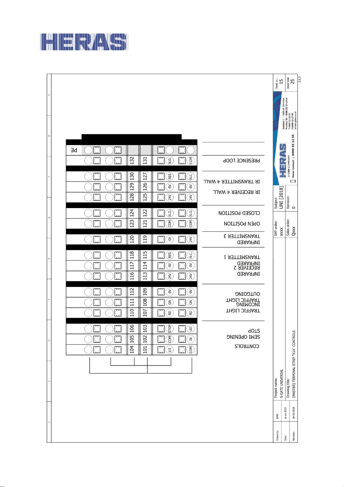
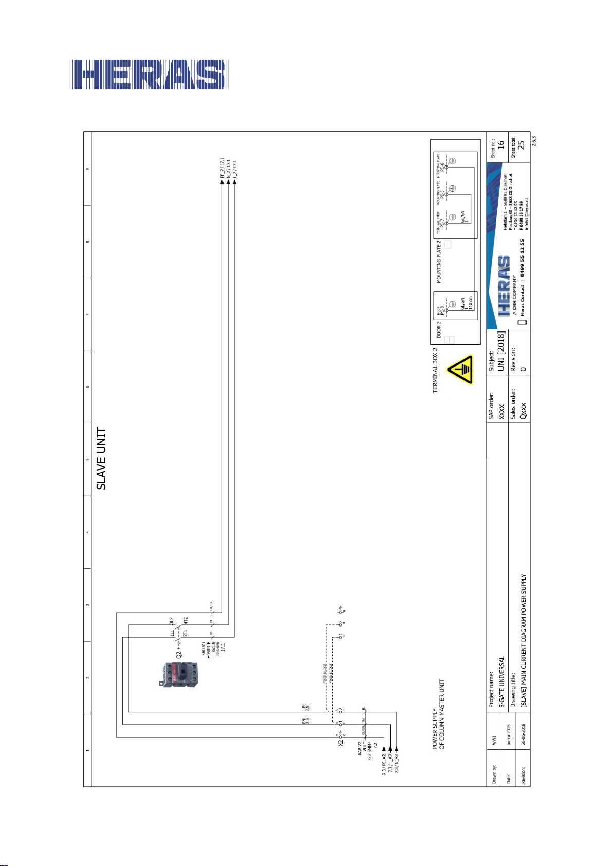
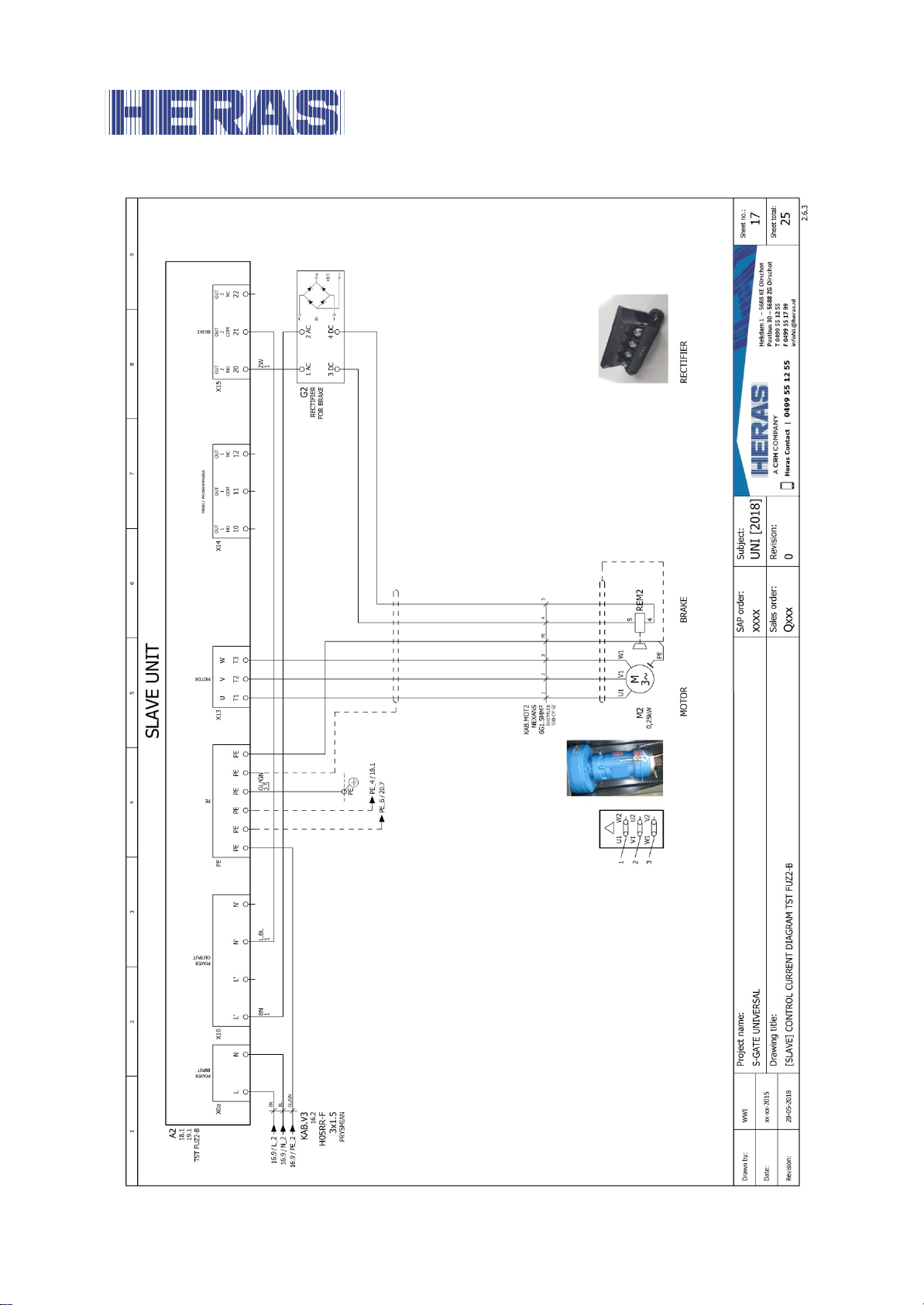
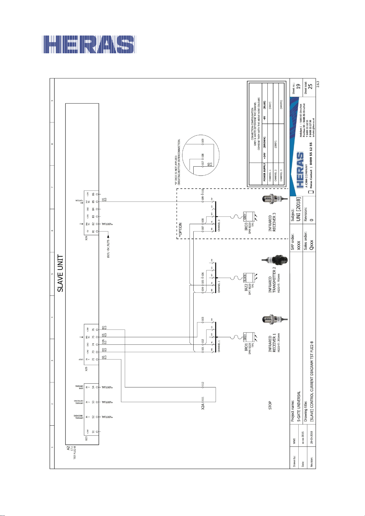
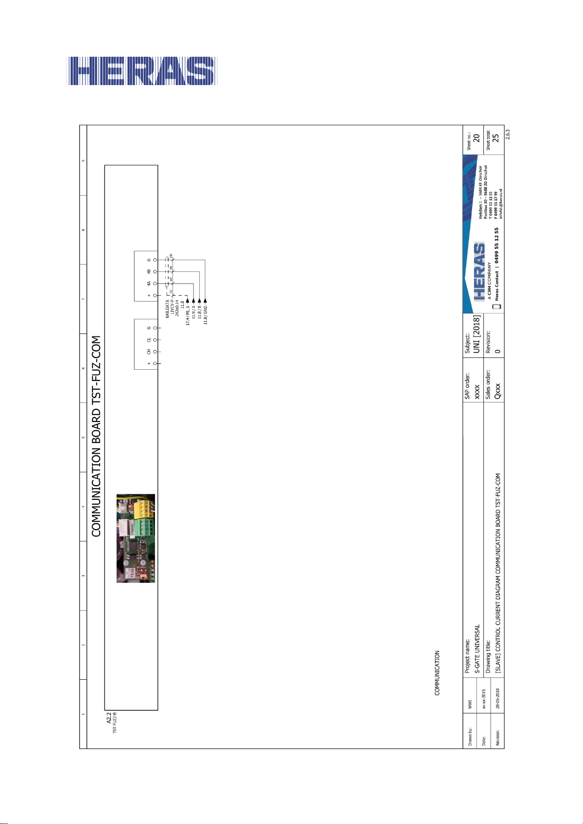
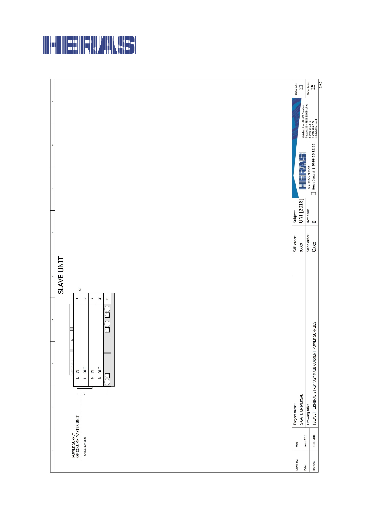
Appendix C: Electric diagram sGate universal
EN – Translation of the original user manual - 3.0 | 2018
Page 28
28
EN – Translation of the original user manual - 3.0 | 2018
Page 29
29
EN – Translation of the original user manual - 3.0 | 2018
Page 30
30
EN – Translation of the original user manual - 3.0 | 2018
Page 31

31
EN – Translation of the original user manual - 3.0 | 2018
Page 32
32
EN – Translation of the original user manual - 3.0 | 2018
Page 33
33
EN – Translation of the original user manual - 3.0 | 2018
Page 34
34
EN – Translation of the original user manual - 3.0 | 2018
Page 35
35
EN – Translation of the original user manual - 3.0 | 2018
Page 36
36
EN – Translation of the original user manual - 3.0 | 2018
Page 37
37
EN – Translation of the original user manual - 3.0 | 2018
Page 38
38
EN – Translation of the original user manual - 3.0 | 2018
Page 39
39
EN – Translation of the original user manual - 3.0 | 2018
Page 40
40
EN – Translation of the original user manual - 3.0 | 2018
Page 41
41
EN – Translation of the original user manual - 3.0 | 2018
Page 42
42
EN – Translation of the original user manual - 3.0 | 2018
Page 43
43
EN – Translation of the original user manual - 3.0 | 2018
Page 44

44
EN – Translation of the original user manual - 3.0 | 2018
Page 45
45
EN – Translation of the original user manual - 3.0 | 2018
Page 46
46
EN – Translation of the original user manual - 3.0 | 2018
Page 47
47
EN – Translation of the original user manual - 3.0 | 2018
Page 48
48
EN – Translation of the original user manual - 3.0 | 2018
Page 49
49
EN – Translation of the original user manual - 3.0 | 2018
Page 50
50
EN – Translation of the original user manual - 3.0 | 2018
Page 51

51
EN – Translation of the original user manual - 3.0 | 2018
Page 52
52
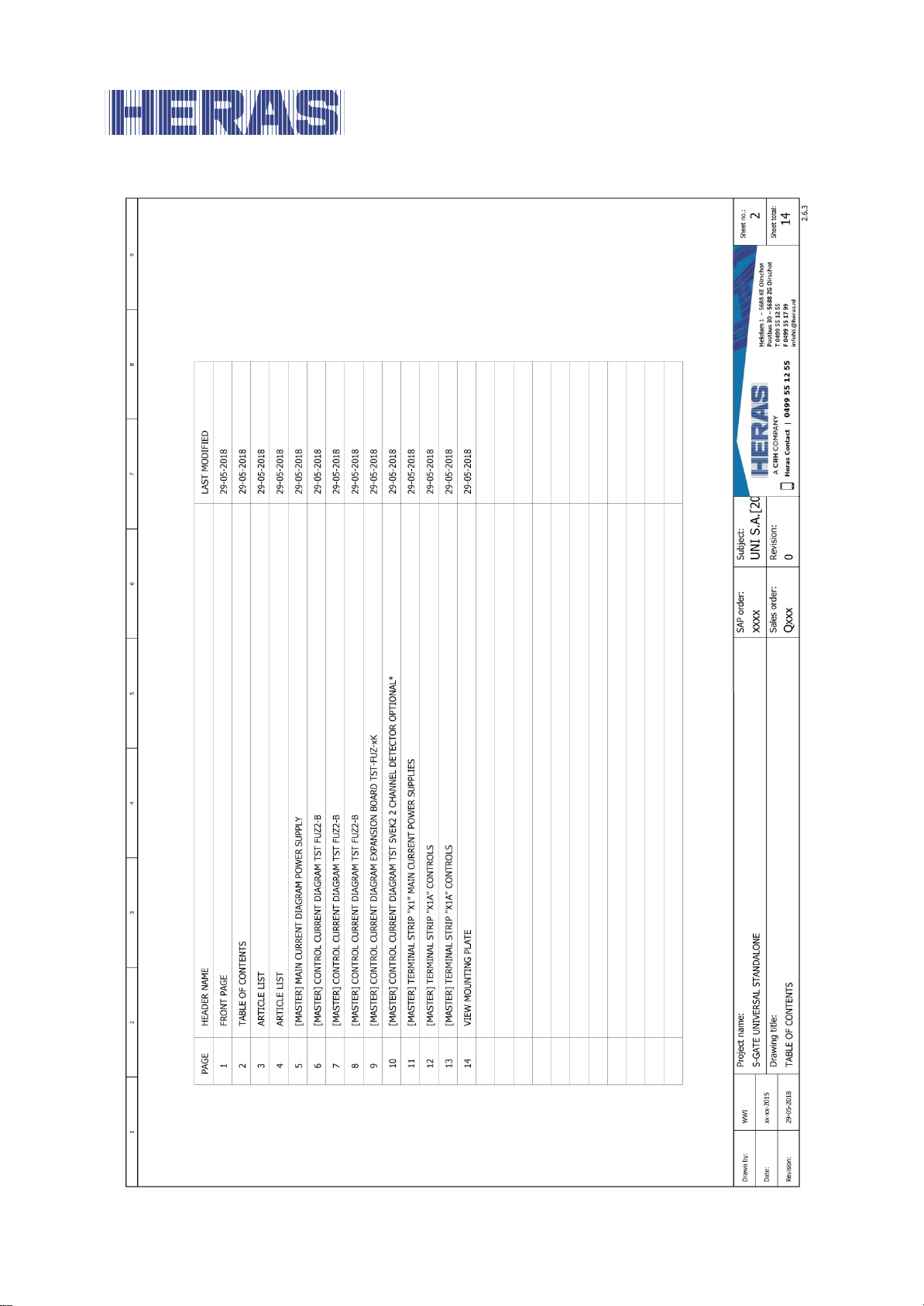
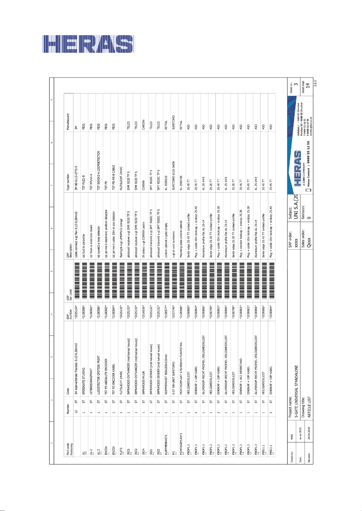
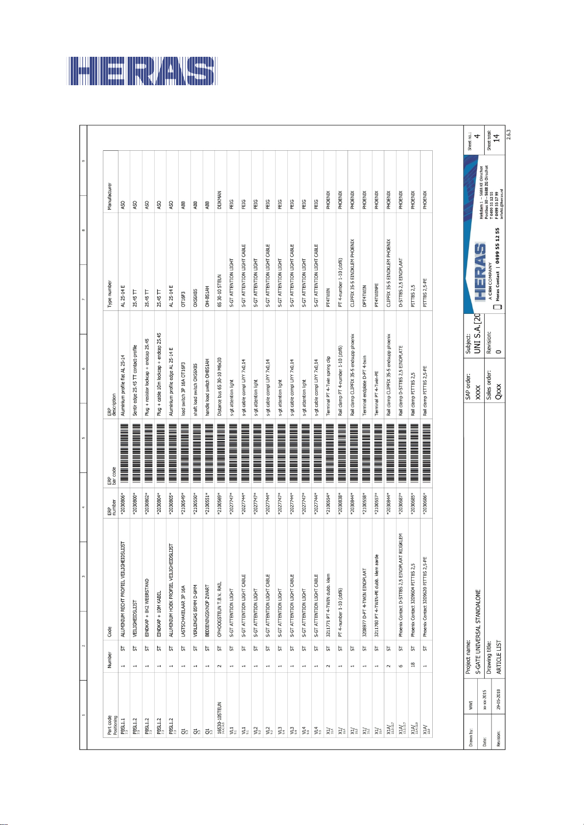
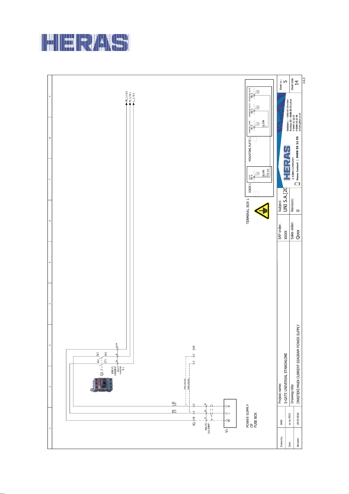
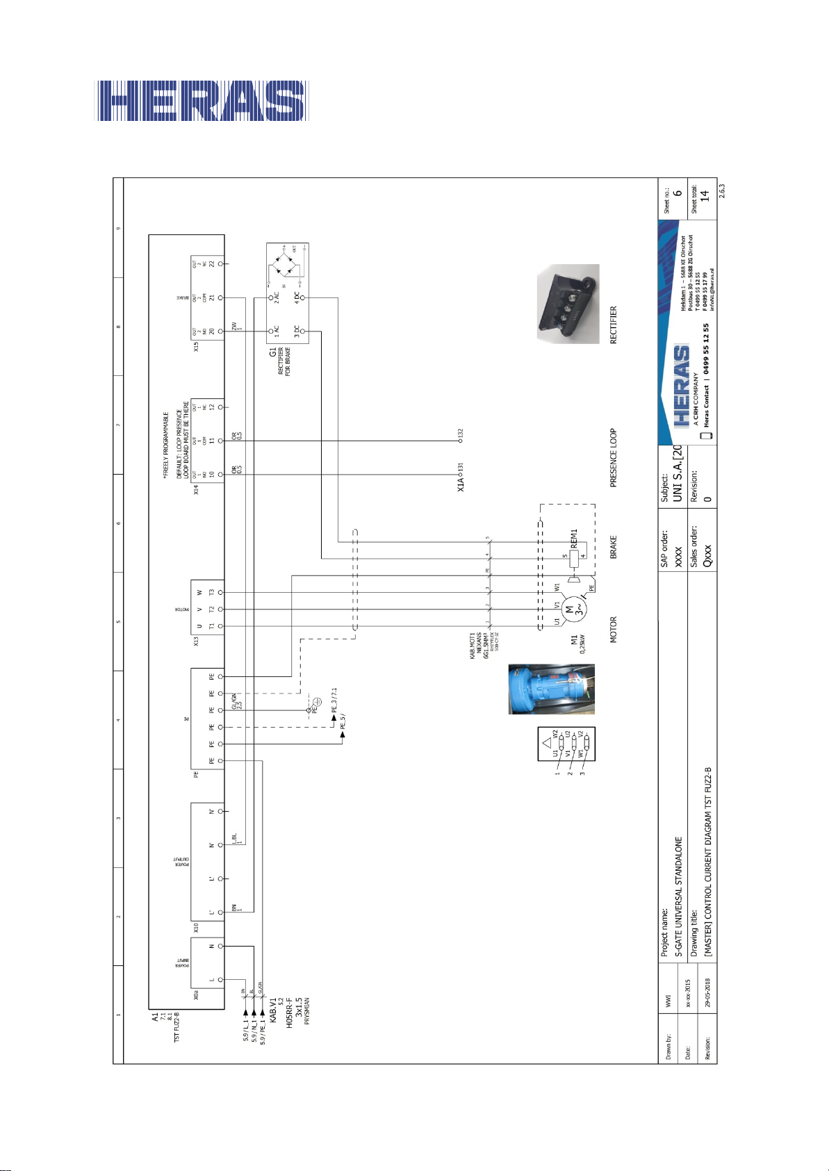
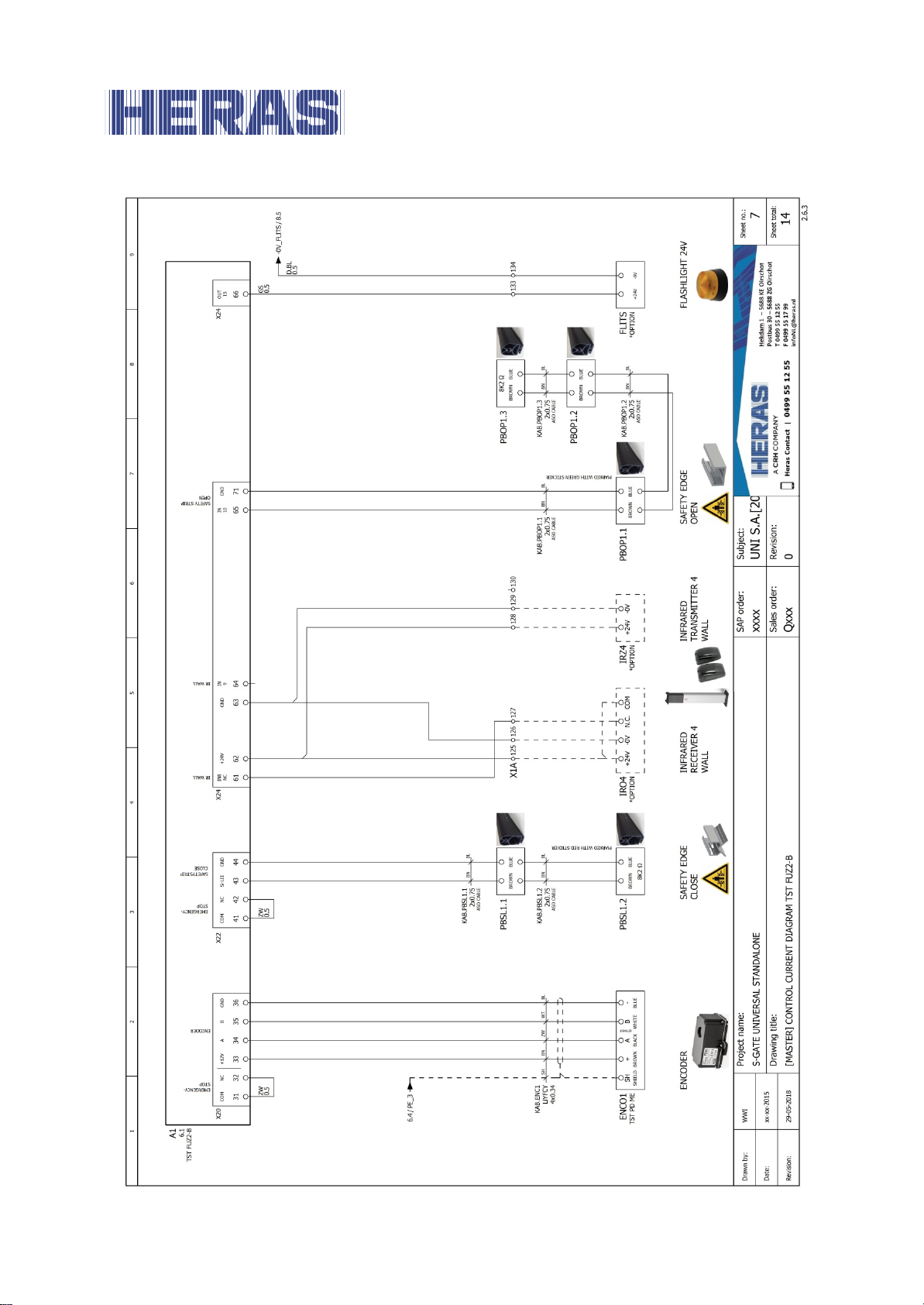
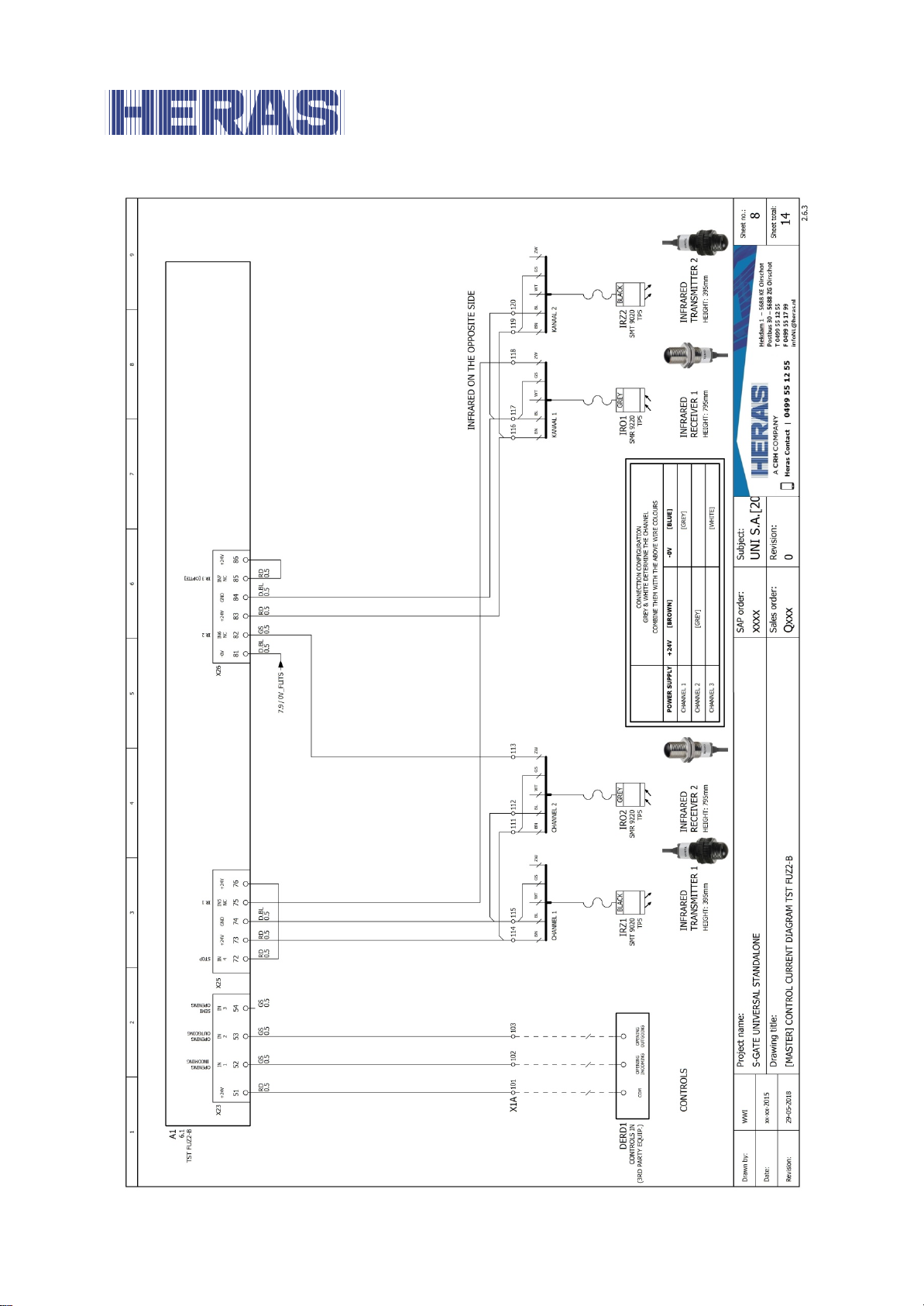
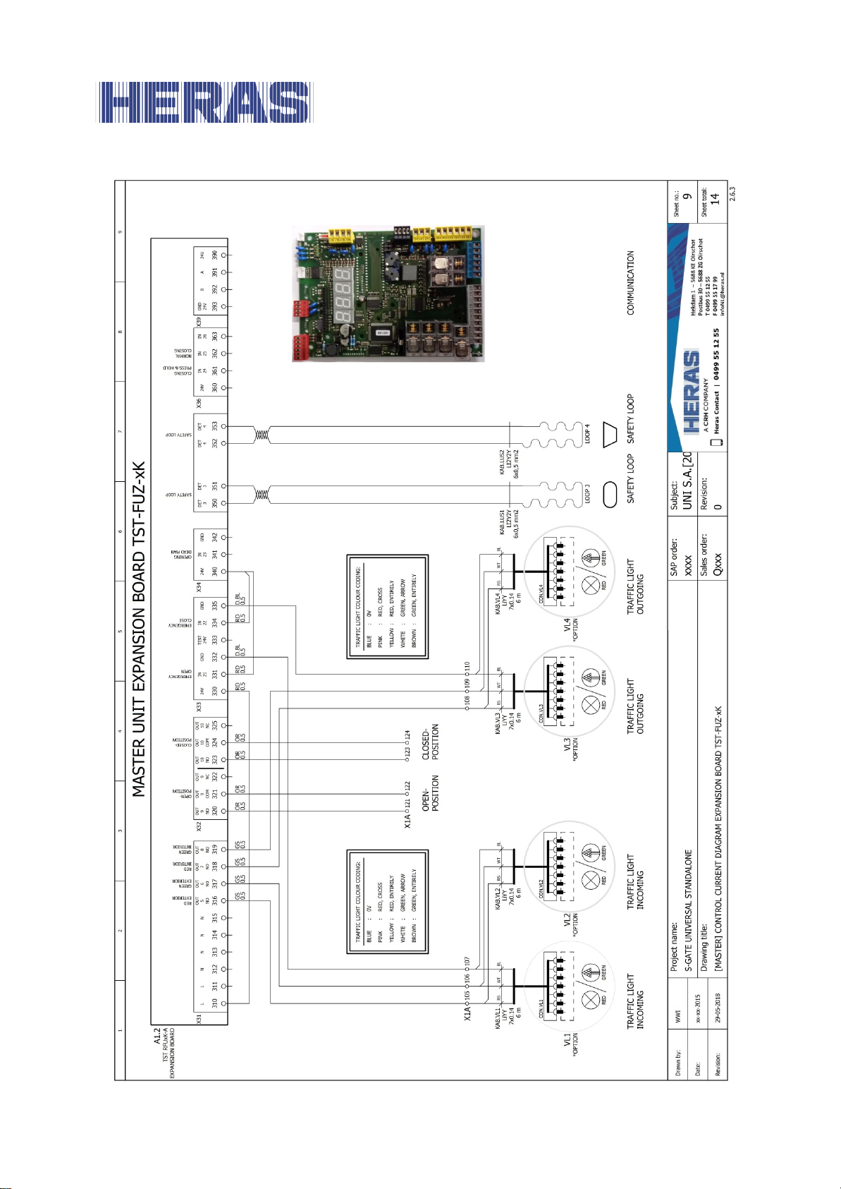
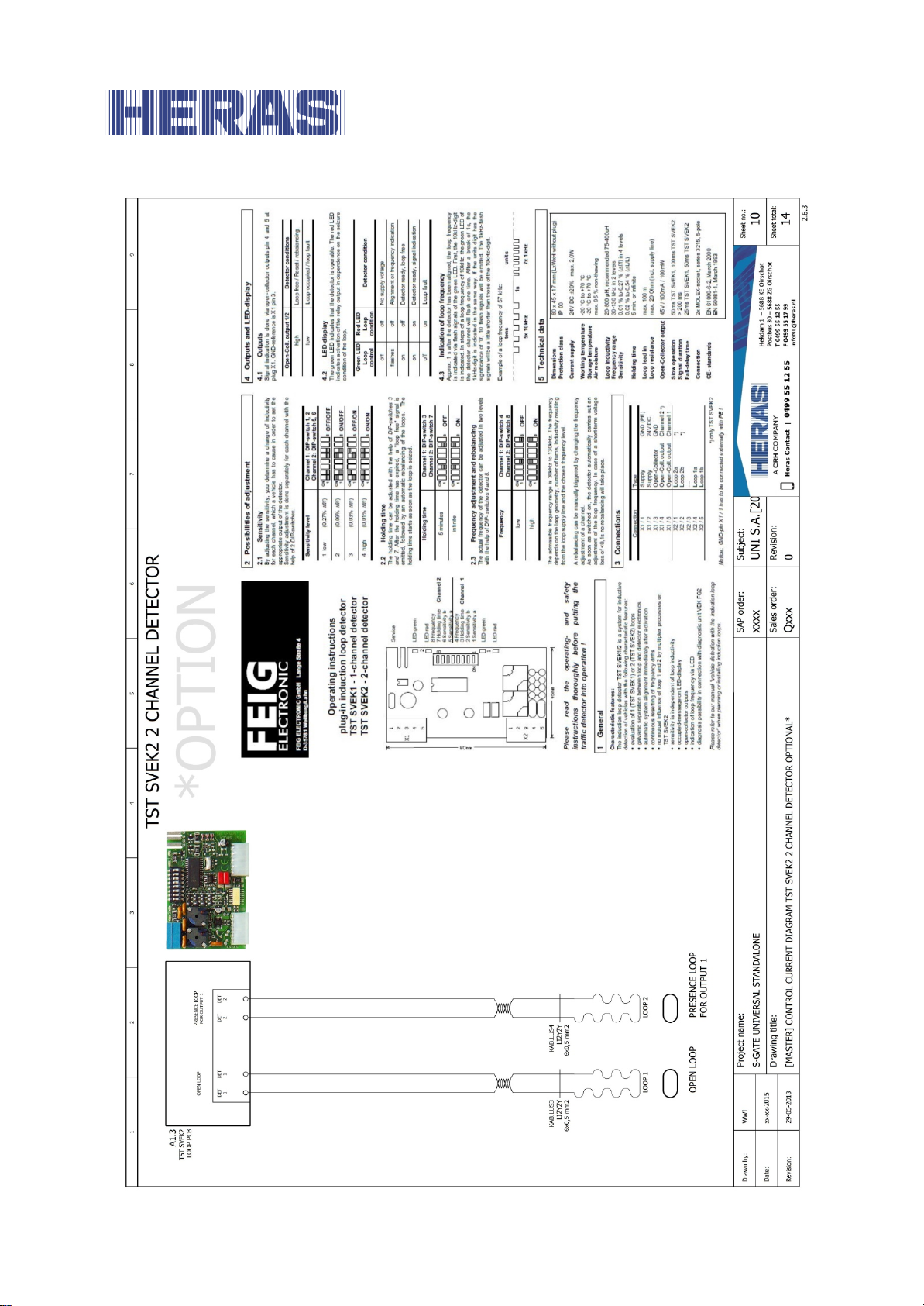
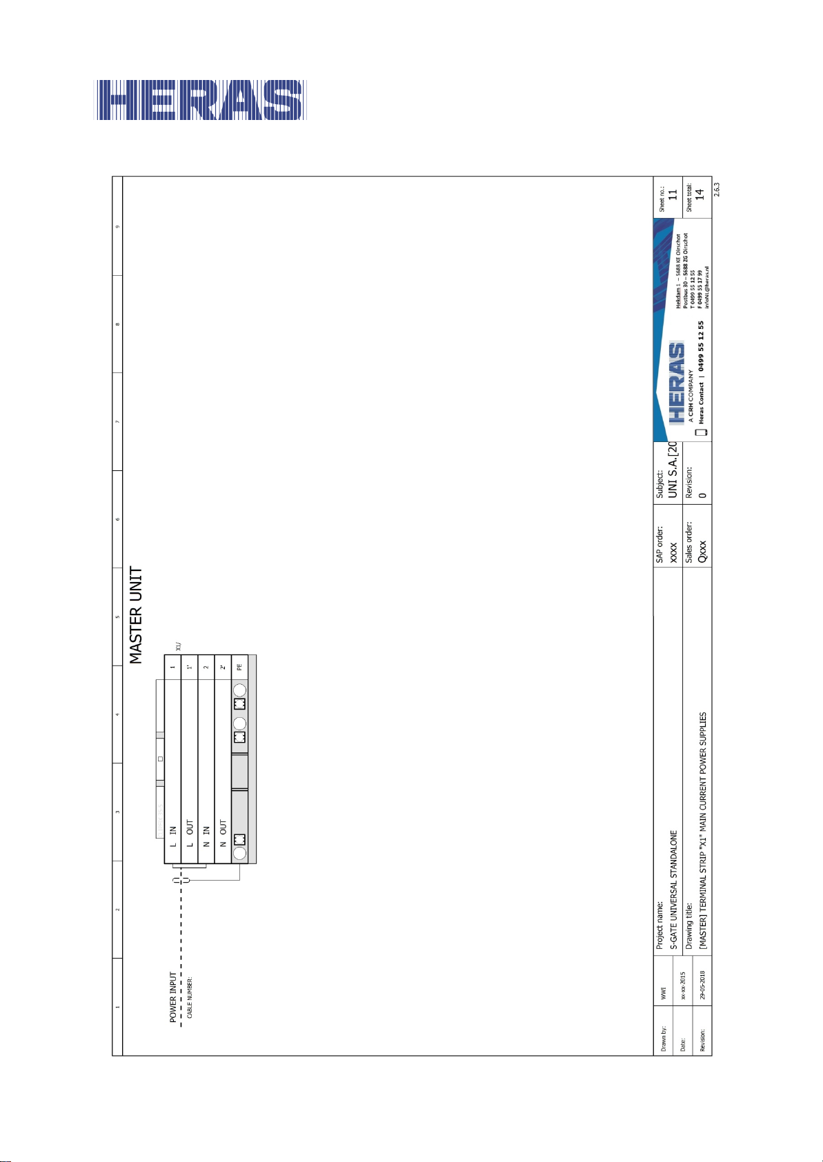
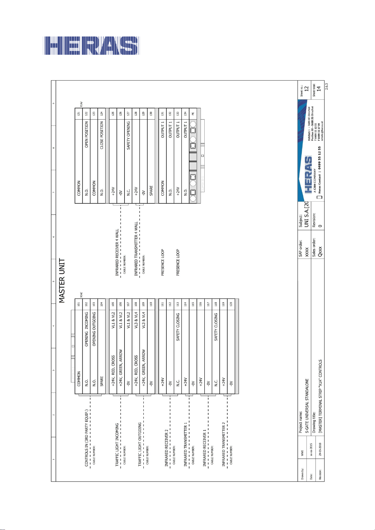
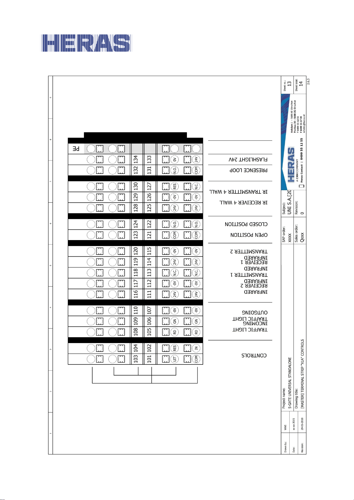
Appendix D: Electric diagram sGate universal
standalone
EN – Translation of the original user manual - 3.0 | 2018
Page 53
53
EN – Translation of the original user manual - 3.0 | 2018
Page 54
54
EN – Translation of the original user manual - 3.0 | 2018
Page 55
55
EN – Translation of the original user manual - 3.0 | 2018
Page 56
56
EN – Translation of the original user manual - 3.0 | 2018
Page 57
57
EN – Translation of the original user manual - 3.0 | 2018
Page 58
58
EN – Translation of the original user manual - 3.0 | 2018
Page 59
59
EN – Translation of the original user manual - 3.0 | 2018
Page 60
60
EN – Translation of the original user manual - 3.0 | 2018
Page 61
61
EN – Translation of the original user manual - 3.0 | 2018
Page 62
62
EN – Translation of the original user manual - 3.0 | 2018
Page 63
63
EN – Translation of the original user manual - 3.0 | 2018
Page 64
64
EN – Translation of the original user manual - 3.0 | 2018
Page 65
65
EN – Translation of the original user manual - 3.0 | 2018
Page 66
Local supplier stamp:
 Loading...