

Hensel Expert D 250, Expert D 500, Expert D 1000 User Manual
Compact flash
Expert D 250 Speed
Expert D 500
Expert D 1000
User manual
Translation of the original German
user manual
Doc. no. 900.0503.00
Version: 08/2017

Contents
Information about this manual and about the manufacturer ................... 5
Keeping this manual on hand .................................................................. 5
Design features in the text ...................................................................... 5
Design features in the figures .................................................................. 5
Copyright ................................................................................................. 6
Manufacturer’s address ........................................................................... 6
Safety ..................................................................................................... 7
Intended use ............................................................................................ 7
Fundamental safety information ............................................................. 7
Prevention of equipment damage and malfunctions .............................. 9
Design features of warning notices ....................................................... 10
Design features of equipment or property damage information .......... 10
Warning and information sign ............................................................... 11
Description ........................................................................................... 12
Overview of scope of delivery ............................................................... 12
Overview of device ................................................................................ 13
Overview of interfaces to other devices ................................................ 14
Overview of the device power supply ................................................... 15
Overview of swivel head ........................................................................ 16
Overview of controls ............................................................................. 17
Task and function .................................................................................. 19
Type plate .............................................................................................. 20
Technical data ........................................................................................ 21
Unpacking the device and checking the scope of delivery ...................... 23
Commissioning the device ..................................................................... 24
Mounting and removing components of the device ............................... 25
Removing and installing the transport cap ............................................ 25
Removing the foam ............................................................................... 27
Installing and removing the illuminant of the model light .................... 28

Installing and removing the protection glass ........................................ 30
Mounting the light shaping tool on/removing it from the device......... 31
Connecting and disconnecting the mains cable .................................... 33
Mounting the device on/removing it from a stand ............................... 34
Rotating and tilting the device .............................................................. 35
Switching over the swivel head and handle .......................................... 37
Mounting the device on/removing it from a pantograph ..................... 39
Mounting the umbrella on/removing it from the device ...................... 41
Operating the device ............................................................................ 42
Activating and deactivating the device ................................................. 42
Trigging a test flash ............................................................................... 42
Activating and deactivating the model light .......................................... 43
Checking the function of the model lamp ............................................. 44
Setting the flash energy ......................................................................... 44
Activating and deactivating the “Flash Check” function ....................... 45
Activating and deactivating the “Audio” function ................................. 45
Synchronizing the device with the camera............................................ 46
Daily flash counter ................................................................................. 48
Activating and deactivating “PM” mode ............................................... 48
Wi-Fi settings ......................................................................................... 49
Error messages ..................................................................................... 54
Transporting and storing the device ...................................................... 57
Servicing the device .............................................................................. 58
Caring for and cleaning the device ........................................................ 58
Replacing a defective protection glass .................................................. 59
Replacing a defective flash tube ............................................................ 60
Replacing a defective model lamp ........................................................ 63
Replacing a defective fuse of the model lamp ...................................... 64

Performing firmware updates ............................................................... 66
Disposing of the device and packaging .................................................. 67
In Germany ............................................................................................ 67
Outside of Germany ............................................................................... 67
EU Declaration of Conformity ................................................................ 68
Accessories ........................................................................................... 69
Protection glass ..................................................................................... 69
Flash tubes ............................................................................................. 69
Illuminant for model light ...................................................................... 69
Fuses ...................................................................................................... 69
Radio remote trigger ............................................................................. 70
Light shaping tool .................................................................................. 70
Additional accessories ........................................................................... 70
Warranty provisions ............................................................................. 71
In Germany ............................................................................................ 71
Outside of Germany ............................................................................... 71
Limitation of liability ............................................................................. 72
Returning a product to Customer Service .............................................. 73

Information about this manual and
about the manufacturer
5
Tips contain additional information, e.g. special information on the
device.
Information about this manual and about the manufacturer
This manual helps you to safely use the Expert D 250 Speed, Expert D 500
and Expert D 1000 devices. The Expert D 250 Speed, Expert D 500 and
Expert D 1000 devices are hereafter called "device" for short.
Keeping this manual on hand
This manual is part of the device.
Always keep this manual together with the device.
Provide this manual when selling the device or passing it on in another
manner.
Design features in the text
Various elements of this manual are provided with specific design features.
This allows you to easily differentiate between the following elements:
Normal text
Action
Bullet points
CONTROLS
Cross-references (see page)
Design features in the figures
If elements are referred to in a key or in the body text, they are provided
with a number (1).
Information about this manual and
about the manufacturer
6
Copyright
This manual contains information that is subject to copyright. Without the
prior written permission of Hensel-Visit GmbH & Co. KG, this manual shall
not be copied, printed, filmed, processed, reproduced or distributed in any
form, in full or in excerpts.
©Hensel-Visit GmbH & Co. KG
All rights reserved.
Manufacturer’s address
Hensel-Visit GmbH & Co. KG
Robert-Bunsen-Str. 3
97076 Würzburg
Phone: +49-931-27881-0
Fax: +49-931-27881-50
E-mail: info@hensel.de
URL: www.hensel.de

Safety
7
Safety
The device has been built according to state-of-the-art technology and
recognized safety-related regulations. During work with and on the device,
however, residual risk remains, which could present a danger to life and
limb. For this reason, the following safety information is to be observed
and followed.
Intended use
The device is used for illuminating photographs indoors.
Intended use also includes reading and understanding this manual, as well
as observing and following all information in this manual, especially the
safety information. In addition, the safety information and all other
information in the instructions of the cameras used and of the radio
remote trigger are to be observed. Any other use is expressly considered
not to be intended use and leads to the voiding of warranty and liability
claims.
Fundamental safety information
Prevention of serious injuries or death from explosions
The device is not explosion-protected. When the flash tube is triggered,
sparks might arise, which could lead to an explosion. Serious injury or
death can result.
Do not use the device in explosive atmospheres.
Prevention of serious injuries or death from electric shock
Improper work on the device can lead to an electric shock.
Only connect the device to a power mains with an intact protective
contactor.
Only use plugs with contacts in perfect condition.
Protect the device from moisture.
Never use a wet device.
Do not open the housing.
Where possible, avoid laying the cable on the ground. If laying on the
ground cannot be avoided, make sure the cables are not damaged by
vehicles or ladders.

Safety
8
Check the device annually for operating safety (see the maintenance
schedule on page 58).
Regularly clean the outside of the device with a dry cloth.
Have damaged cables and the device replaced immediately by the
authorized Customer Service only.
Prevention of serious injuries due to fire
When the flash tube is triggered, sparks might arise, which could lead to
fire. Serious injuries can result.
Do not use the device in the vicinity of flammable materials such as
decorative materials, paper, etc.
Do not store flammable materials such as decorative materials, paper,
etc. in the vicinity of the device.
Prevention of serious skin and eye injuries
Triggering a flash in the direct vicinity of the eyes can result in skin and eye
injuries.
Observe the required minimum distance for the type of light shaping
tool and flash intensity.
Do not look into the light shaping tool in case the flash is triggered
accidentally.
In case of skin or eye injuries, consult a doctor immediately.
Prevention of the risk of burns
Heat is generated during the operation of the device. This heat can heat up
the flash tube, model light, protection glass and light shaping tool,
resulting in burns in case of contact with the skin.
Always handle the device with gloves according to EN 407 during
operation.
Always let the device cool down for 5 to 10 minutes before mounting or
removing components.
Prevention of ozone formation
When using the device in enclosed spaces, ozone can form.
To prevent an increased ozone concentration, vent enclosed spaces
regularly.

Safety
9
Prevention of equipment damage and malfunctions
Prevention of equipment damage due to fogging
Fogging can occur due to a sudden temperature change, e.g. in a new
environment.
Always let the device acclimatize before use in a new environment.
Prevention of equipment damage due to rain, vapors, frost, heat, humidity and dust
Rain, vapors, frost, heat, humidity and dust can damage the device.
Protect the device against dripping and spraying water (e.g. rain) or
vapors.
Protect the device against frost, heat and high humidity.
Do not place containers of liquids on the device.
Make sure that neither the device nor its components are standing or
lying on wet ground.
Do not store the device in locations exposed to heat or moisture.
Cover the device with suitable dust protection when it is not in
operation.
Prevention of equipment damage when using external products
The use of the device in combination with external products can lead to
equipment damage.
Use the device only with accessories and original spare parts
recommended by the manufacturer.
Malfunctions due to electromagnetic radio signals
The device transmits and receives electromagnetic radiation in a frequency
range from 2.3995 to 2.4745 GHz according to IEEE 802.11 n. The
maximum transmission power is 100 mW. The power, range and reliability
can be impaired by other radio systems or the device can cause
interference in other radio systems, such as radio telephones (cell phones,
cordless telephones), Wi-Fi routers, radio and TV stations or medical
devices.
Before using the device in sensitive environments, such as hospitals,
make sure that use is permitted there.
Safety
10
DANGER
Notices with the word DANGER warn about a dangerous
situation that could lead to death or serious injuries.
WARNING
Messages with the word WARNING warn about a
dangerous situation that could lead to death or serious
injuries.
CAUTION
Notices with the word CAUTION warn about a situation that
could lead to light or medium-scale injuries.
IMPORTANT!
This information warns against a situation that can lead to
equipment or property damage.
Design features of warning notices
This user manual contains the following safety information:
Design features of equipment or property damage information
Safety
11
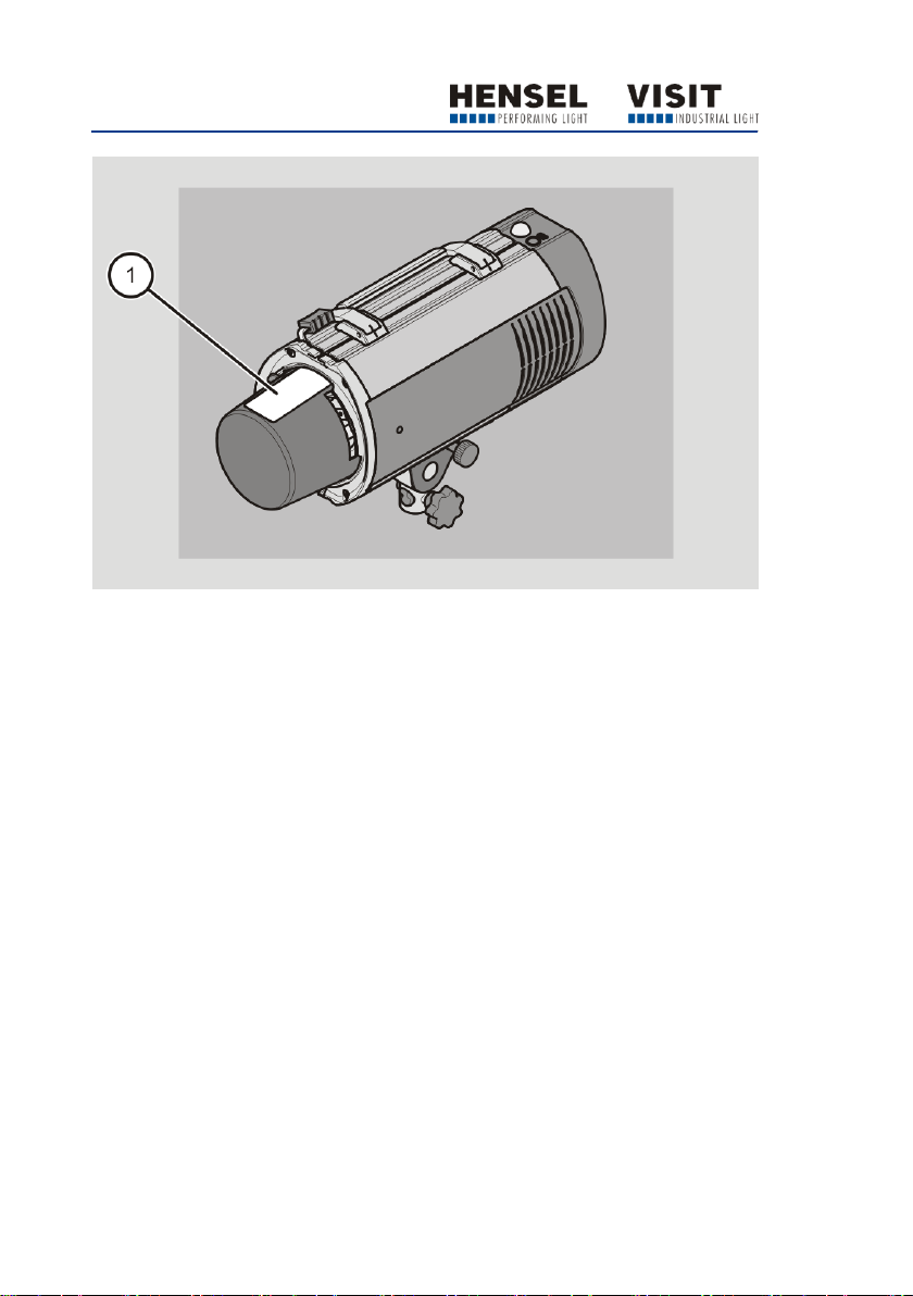
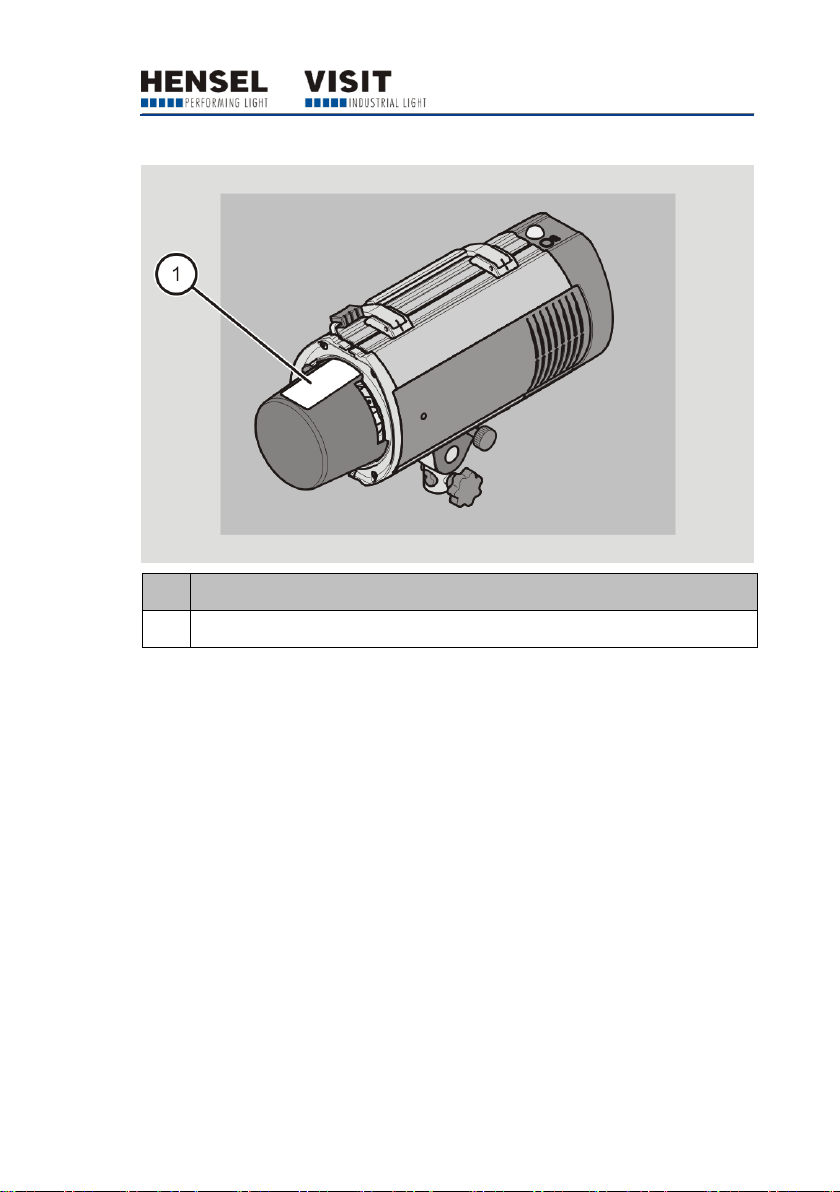
No.
Explanation
1
Remove the transport cap before commissioning
Warning and information sign
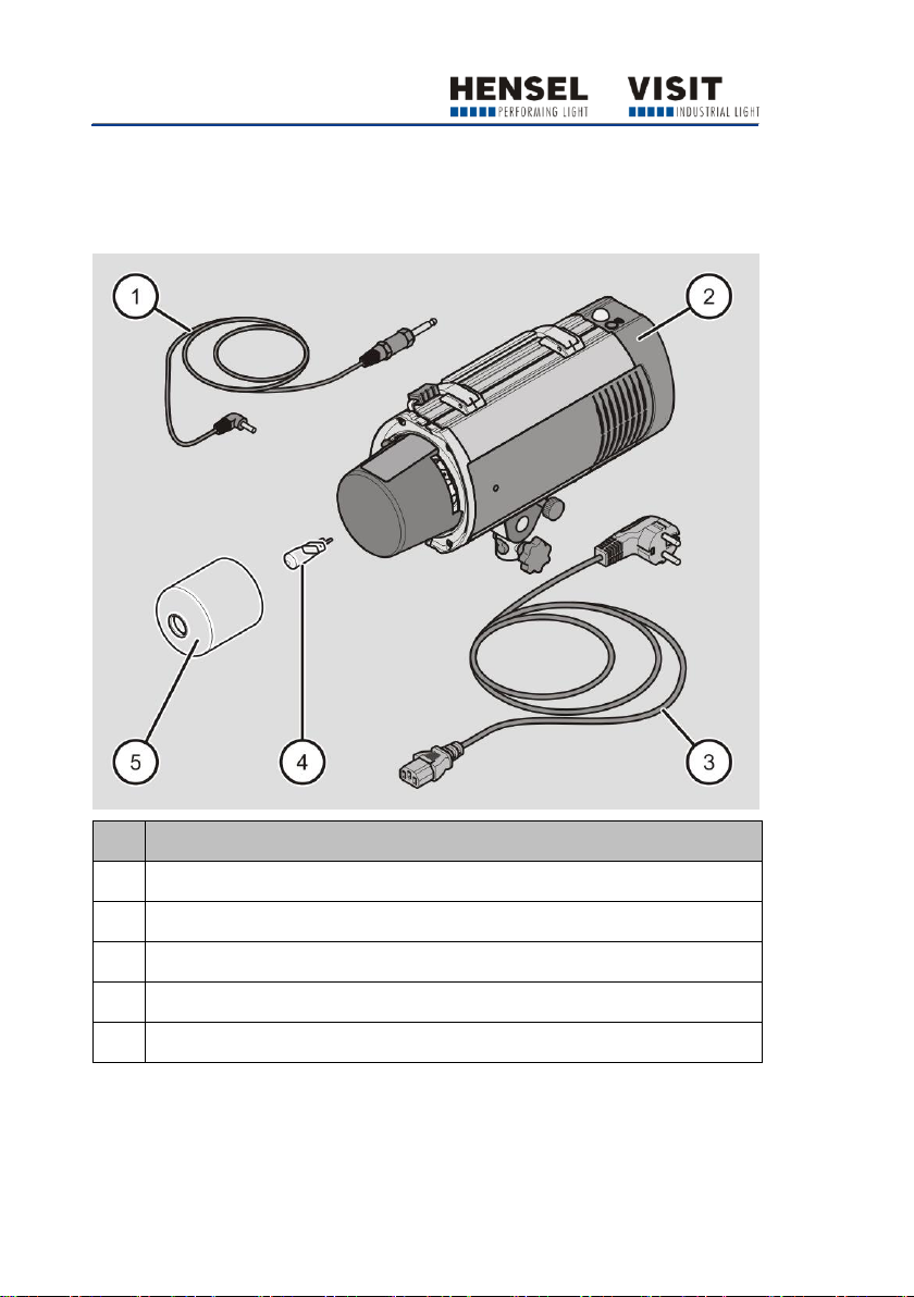
Description
12
No.
Designation
1
Sync cord
2
Device
3
Mains cable (country-specific, shown as an example)
4
Illuminant for the model light (packed separately)
5
Protection glass (packed separately)
Description
Overview of scope of delivery
Description
13
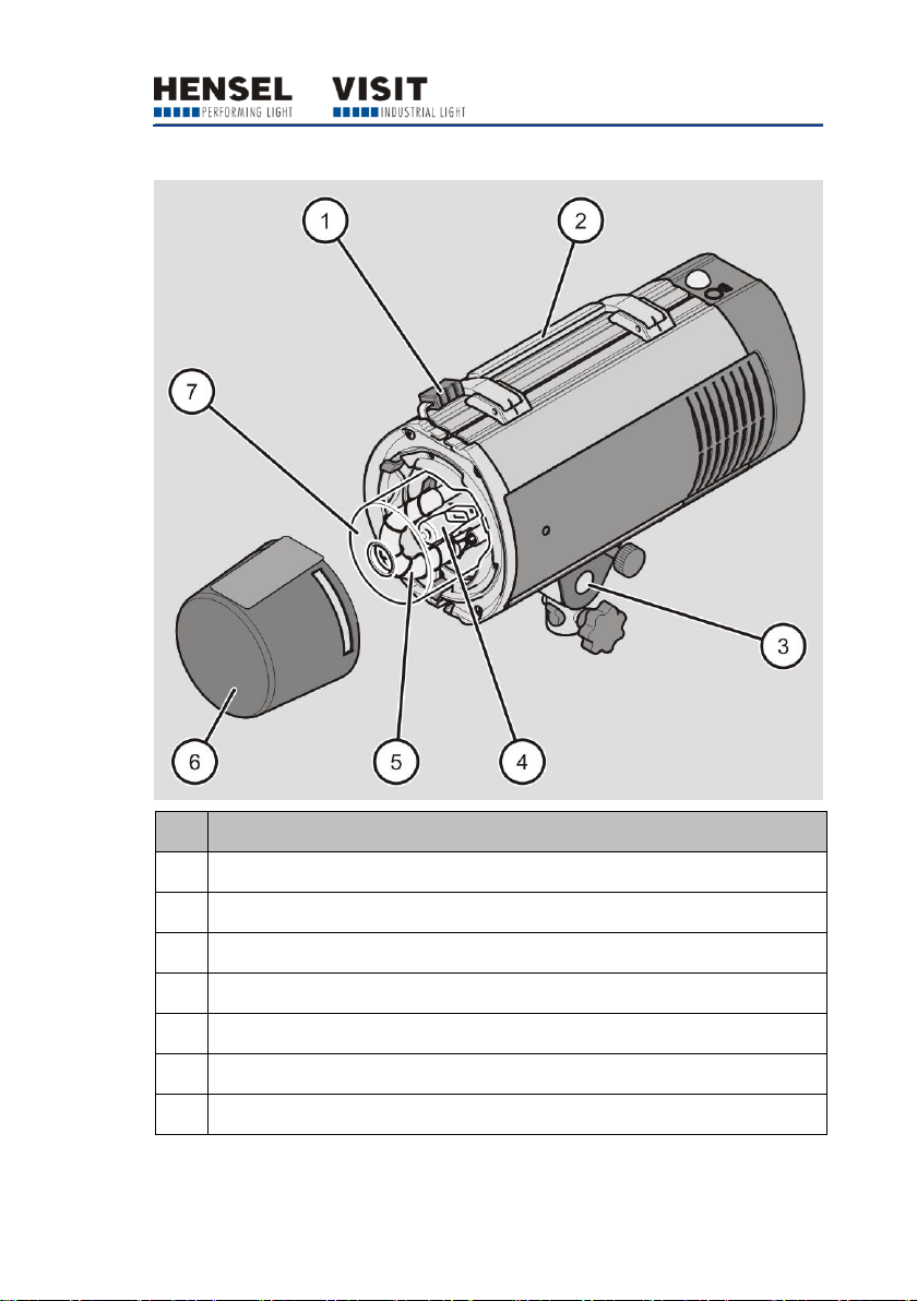
No.
Designation
1
Lock of the holder for the light shaping tool and transport cap
2
Handle (can be switched over)
3
Swivel head (can be switched over)
4
Illuminant for the model light
5
Flash tube
6
Transport cap
7
Protection glass
Overview of device
Description
14
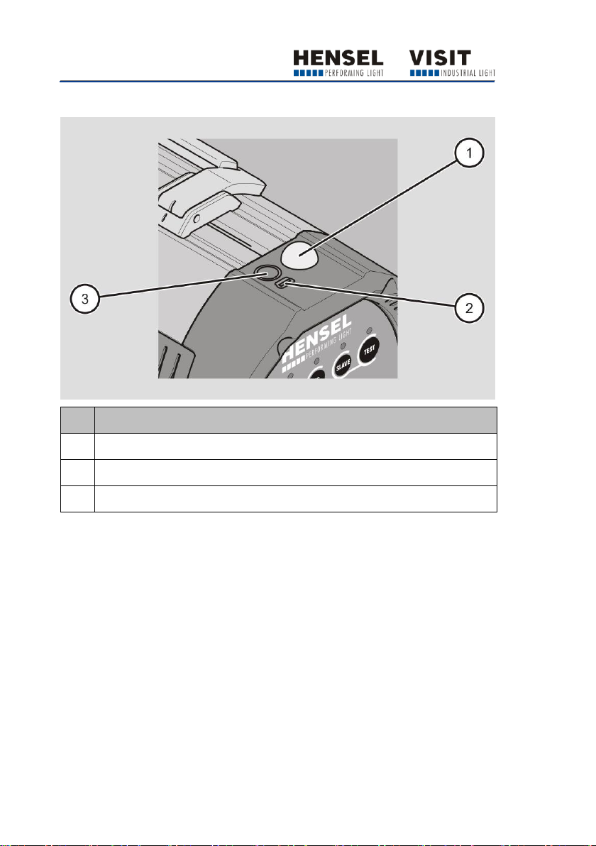
No.
Designation
1
Photo cell
2
USB port for firmware updates
3
Sync socket
Overview of interfaces to other devices
Description
15
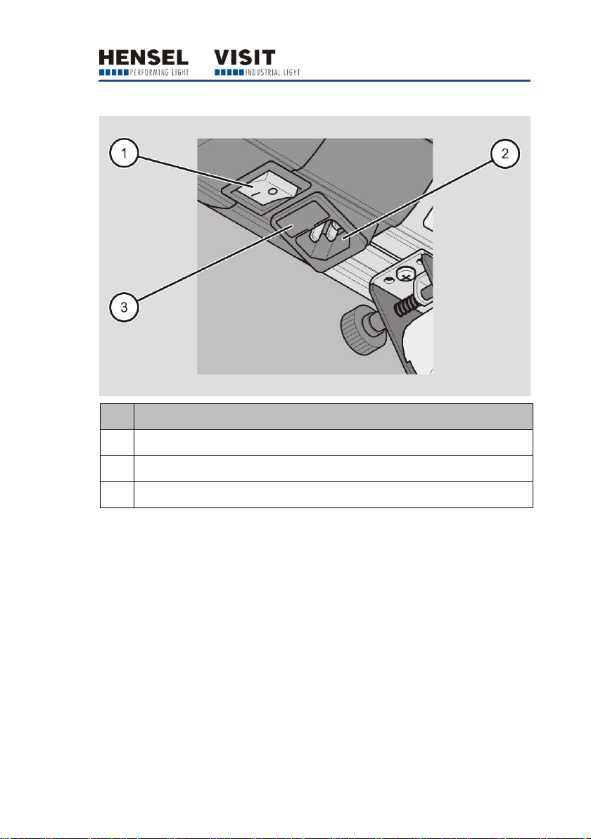
No.
Designation
1
Main switch ON/OFF
2
Mains socket
3
Fuse holder
Overview of the device power supply
Description
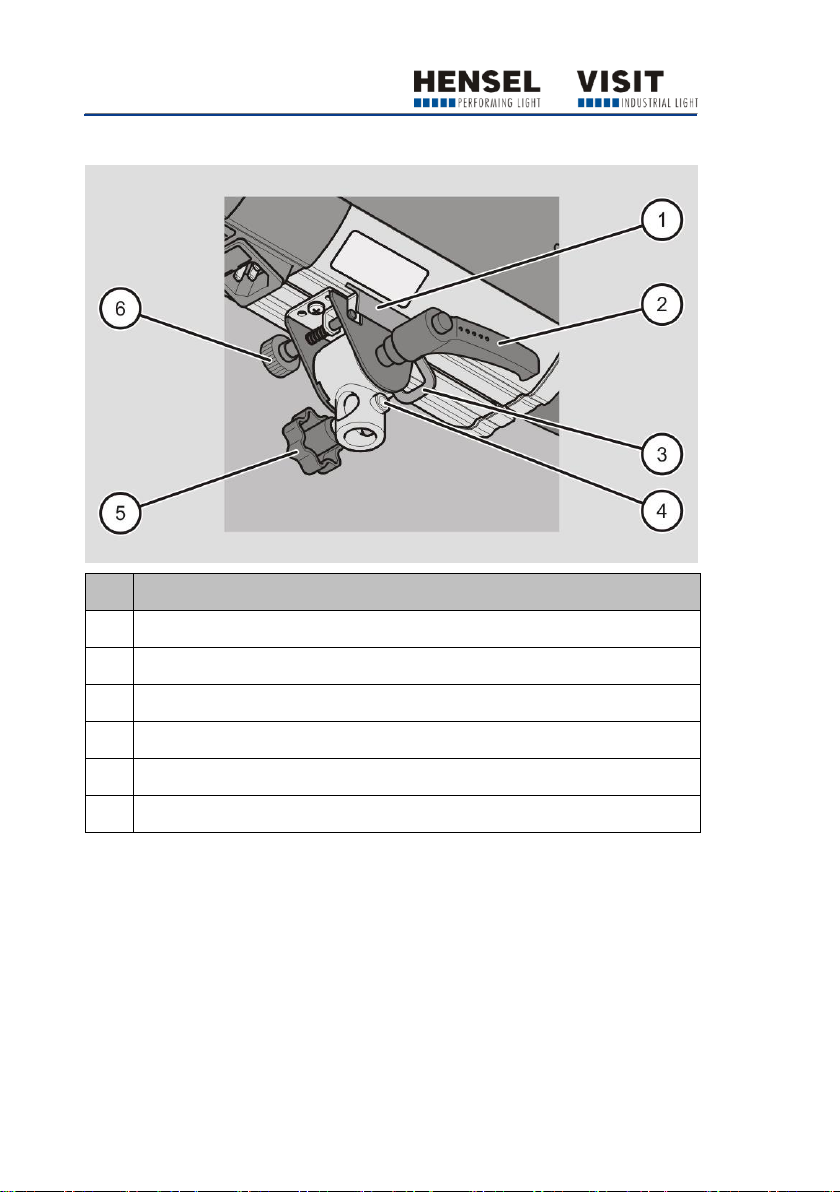
16
No.
Designation
1
Umbrella holder
2
Locking lever
3
Hanger clip for safety rope
4
Thread for locking screw
5
Knurled screw for stand adapter
6
Knurled screw for umbrella holder
Overview of swivel head
Description
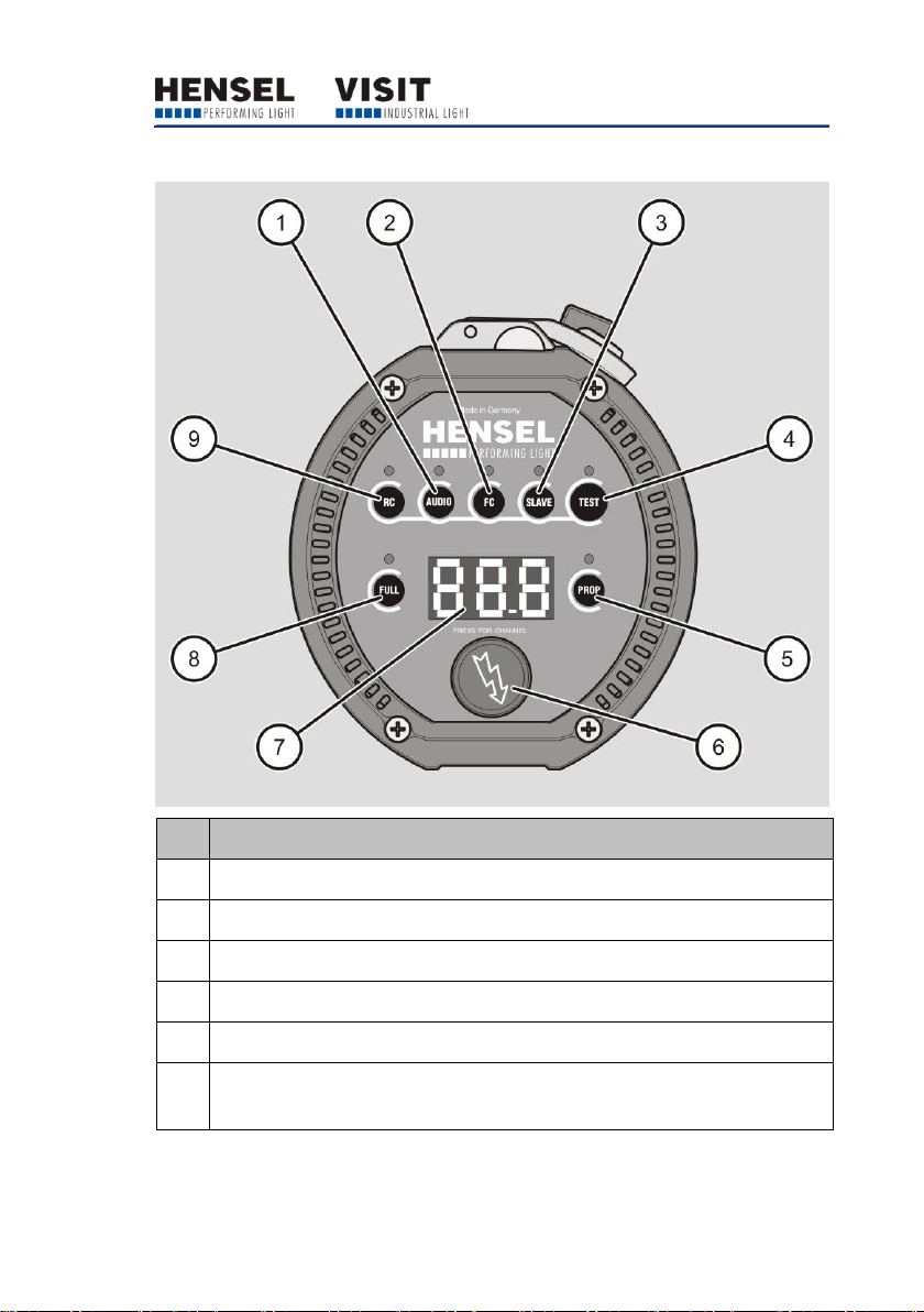
17
No.
Designation
1
AUDIO: Signal tone for activation and deactivation of flash readiness
2
FC: Activation and deactivation of “Flash Check”
3
SLAVE: Activating and deactivating the photo cell
4
TEST: Manual triggering of flash
5
PROP: Activation and deactivation of the model light in “Prop” mode
6
Rotary switch for the selection of flash energy, radio channels and Wi-Fi
settings
Overview of controls

Description
18
No.
Designation
7
Display for the indication of flash energy, radio channels, flash counter
and Wi-Fi settings
8
FULL: Activation and deactivation of the model light in “Full” mode
9
RC: Activation and deactivation of the radio receiver/channel selector
LED displays are located above the buttons on the display. They light up
when the buttons are activated.

Description
19
Task and function
The device is used for illuminating photographs indoors. It can be used on
a stand or pantograph.
The device has a bright and proportionally adjustable model light. In
addition, the device is equipped with an “Autored” automatic model light
reduction. After a preset time of 35 minutes, the brightness is dimmed to
half (level 9) in “Full” mode. In “Prop” mode, the brightness is reduced to
half when the flash energy is set in a range from 9.1 to 10.
Synchronization with the camera takes place using a sync cord, the built-in
photo cell or the built-in radio receiver. Using the jack plug, the device is
connected to the camera through the sync socket. The flash is triggered
through the photo cell by the striking of a flash emitted by another device.
With the optionally available radio remote trigger, the camera and flash
can be synchronized via radio triggering.
The device has an integrated Wi-Fi module. With this module, important
functions like flash energy, model light and synchronization can be remotecontrolled by a smart device or desktop/laptop computer. When several
devices are actuated, they can be controlled individually, in groups or
globally in a team. Devices of a team can be controlled centrally by up to
two apps at the same time. A team can comprise up to twelve devices. In
parallel with this team, nine additional teams can be set.

Description
20
Type plate
The type plate is attached to the housing. You will find the following
information on the type plate:
Manufacturer name
Name of the model
Code number
CE marking
Symbol for environmentally sound disposal
Country of manufacturing

Description
21
Device type
Expert
D 250 Speed
Expert
D 500
Expert
D 1000
Article number
8390 SW
8350 SW
8360 SW
Nominal energy
250 J
500 J
1000 J
Guide number 1
1 m = 64
2 m = 32
1 m = 90
2 m = 45
1 m = 128
2 m = 64
Minimum
flash duration 2
1/10,000 s at 64
Ws
1/5,600 s at 125
Ws
1/3,000 s at 250
Ws
Maximum
flash duration 2
1/4,000 s
1/2,000 s
1/1,500 s
Minimal recycling
time
0.04 s
0.11 s
0.14 s
Maximum
recycling time
0.2 s
0.5 s
1.0 s
Flash energy
regulation
9 f-stop
8 f-stop
Weight
Approx. 3.1 kg
Approx. 3.4 kg
Approx. 3.9 kg
Overall
dimensions
L x W x H in cm
33 x 13.1 x 19.7
35 x 13.1 x 19.7
38.5 x 13.1 x 19.7
Protection glass
9454660
9454638, transparent
Flash tube
9450420, plug-in style, single coating
Model light
300 W/G6.35/115 V and/or 300 W/G6.35/230 V
Model light
regulation
Off, Full, Proportional, Autored
Sync
socket/voltage
6.3 mm jack, mono /5 V DC
Radio receiver
Strobe Wizard Plus and freemask integrated
Technical data

Description
22
Device type
Expert
D 250 Speed
Expert
D 500
Expert
D 1000
Fuses
F 4 A H, 5 x 20 mm
Mains connection
Multi-voltage 90–230 V
Connection for
light shaping tool
reflector quick-change mechanism for EH (10 cm)
Additional
features
Thermal monitoring of the power electronics, integrated
Wi-Fi module
Daily flash
counter
Resettable
Fan
Built-in
Photo cell
Switchable
Flash Check
Switchable
Model light
reduction
Autored
Internal power
drop in case of
power reduction
APD (automatic power drop)
Display
7-segment for flash energy, daily flash counter, channel
display, “Autored” mode, error
User interface
Embossed membrane keypad with buttons, fluorescent,
Hensel user logic
Subject to technical change.
The specified data constitutes typical values that can be subject to fluctuations
due to the tolerances of the components used.
1
Measured at 100 ASA, exposure time 1/60 s, 100 % flash energy and 12”
reflector at a distance of 1 m and 2 m.
2
The specification of the flash duration refers to the half-life t
0.5
.

Unpacking the device and checking the
scope of delivery
23
Unpacking the device and checking the scope of delivery
Remove the product from the packaging.
Keep the original packaging in case you need to return the product to
Customer Service.
Check the scope of delivery for correctness and completeness (see
page 12).
Make sure all parts are undamaged.
In case of deviations, contact the manufacturer and/or dealer
immediately.
 Loading...