

Page 1

330000 SSeerriieess
OOiill DDiissppoossaall SShhuuttttllee
OPERATION
MANUAL
ODS 300
ODS 310
FM07-635J
Page 2

Page 3

Table of Contents
Safety......................................................................................................................... iii
Chapter 1 Introduction.....................................................................................................1
1.1 Introduction ...........................................................................................................1
1.2 Technical Support ..................................................................................................1
1.3 Model Configuration and Identification .....................................................................1
1.4 Dimensions and Weights ........................................................................................1
Chapter 2 Assembly .......................................................................................................3
2.1 Model 300 .............................................................................................................3
2.1.1 Components....................................................................................................3
2.1.2 Apply Label .....................................................................................................4
2.1.3 Prepare Connections .......................................................................................4
2.1.4 Attach Handle..................................................................................................5
2.1.5 Attach Handle Bracket......................................................................................5
2.1.6 Attach Down Pipe ............................................................................................6
2.1.7 Attach Drain Pipe .............................................................................................6
2.2 Model 310 .............................................................................................................7
Chapter 3 Basic Operation..............................................................................................9
3.1 Shuttle Setting .......................................................................................................9
3.2 Shuttle Position....................................................................................................10
3.3 Oil Disposal ......................................................................................................... 10
3.4 Add Oil ................................................................................................................ 11
3.5 Cleaning the ODS ................................................................................................ 11
Chapter 4 Model 300 Parts ............................................................................................13
Chapter 5 Model 310 Parts ............................................................................................17
5.1 Upper Stand-Pipe Assembly ................................................................................. 19
5.2 Lower Flexible Stand-Pipe Assembly..................................................................... 20
Chapter 6 Accessories .................................................................................................. 21
6.1 Filter Hose...........................................................................................................21
Contents
i
Page 4

Contents
ii
Page 5

SSaaffeettyy
Henny Penny fryers have many safety features incorporated. However, the only way
to ensure safe operation is to fully understand the proper installation, operation, and
maintenance procedures. The instructions in this manual have been prepared to aid
you in learning the proper procedures. Where information is of particular importance
or is safety related, the words DANGER, WARNING, CAUTION, or NOTICE are used.
Their usage is described as follows:
DDAANNGGEERR!! indicates hazardous situations which, if not
avoided, will result in death or serious injury.
DDAANNGGEERR!!
WWAARRNNIINNGG!! indicates hazardous situations which, if not
avoided, could result in death or serious injury.
WWAARRNNIINNGG!!
CCAAUUTTIIOONN!!
NOTICE
CCAAUUTTIIOONN!! indicates hazardous situations which, if not
avoided, could result in moderate or minor injury.
NOTICE
ing property damage.
is used for information considered important regard-
Preface
iii
Page 6

These are the original version controlled Henny Penny instructions for the model 300
and 310 Oil Disposal Shuttle (ODS). This manual is available on the Henny Penny
Public website (www.hennypenny.com). Read these instructions completely prior to
installation and operation of this appliance to ensure compliance to all required
installation, operation and safety standards. Read and obey all safety messages to
avoid damage to the appliance and personal injury.
BBuurrnn rriisskk!! AAllwwaayyss wweeaarr PPeerrssoonnaall PPrrootteeccttiivvee
EEqquuiippmmeenntt ((PPPPEE)) wwhheenn uussiinngg aann OOiill DDiissppoossaall
SShhuuttttllee ((OODDSS)).. PPeerrssoonnaall iinnjjuurryy oorr sseerriioouuss bbuurrnnss
ccaann rreessuulltt ffrroomm ssppllaasshhiinngg hhoott ooiill..
This appliance is intended for commercial use in kitchens of restaurants, bakeries,
hospitals, etc. but not for the continuous mass production of food such as in a factory
setting. All repairs must be performed by the manufacturer, its service agent or
similarly qualified persons in order to avoid a hazard.
This appliance is not intended for use by persons (including children) with reduced
physical, sensory or mental capabilities, or lack of experience and knowledge, unless
they have been given supervision or instruction concerning use of the appliance by a
person responsible for their safety. Children should be supervised to ensure that they
do not play with the appliance.
Preface
iv
Page 7

CChhaapptteerr 11 IInnttrroodduuccttiioonn
11..11 IInnttrroodduuccttiioonn
This guide takes Operators through all the aspects that make up the model 300 and
310 Oil Disposal Shuttles.
11..22 TTeecchhnniiccaall SSuuppppoorrtt
Should you require assistance from technical support inside the U.S. or Canada, contact Henny Penny Technical Support. at 800-417-8405 or
[email protected] for all service
needs. Outside of the U.S. contact technicalservice[email protected] or your local distributor for
assistance.
11..33 MMooddeell CCoonnffiigguurraattiioonn aanndd IIddeennttiiffiiccaattiioonn
There are two basic configurations. The 300 for Evolution Elite and LOV fryers, and
the 310 for the F5 fryer. The main difference between the two models is the downpipe, which runs between the drain pan and the oil pump, and the drain pan switch.
The 300 model uses a straight down-pipe and a mechanical drain pan switch, and the
310 uses a curved flex-pipe and magnetic drain pan switch.
11..44 DDiimmeennssiioonnss aanndd WWeeiigghhttss
Introduction
1
Page 8

Introduction
2
Page 9

CChhaapptteerr 22 AAsssseemmbbllyy
This section provides the assembly instructions for the 300 /310 series Oil Disposal
Shuttle (ODS).
22..11 MMooddeell 330000
HHeeaavvyy oobbjjeecctt!! SSeeee tthhee ttaabbllee iinn 11..44
IINNFFOO:
aanndd WWeeiigghhttss
wwhheenn mmoovviinngg tthhee sshhuuttttllee ccoommppoonneennttss ttoo pprreevveenntt
ppeerrssoonnaall iinnjjuurryy..
AAnnyy sshhiippppiinngg ddaammaaggee sshhoouulldd bbee nnootteedd iinn tthhee
pprreesseennccee ooff tthhee ddeelliivveerryy aaggeenntt aanndd ssiiggnneedd pprriioorr ttoo
hhiiss oorr hheerr ddeeppaarrttuurree..
,, ppaaggee 11 ffoorr tthhee wweeiigghhtt.. TTaakkee ccaarree
22..11..11 CCoommppoonneennttss
Unpack and check to ensure all parts are present and undamaged.
DDiimmeennssiioonnss
Assembly
3
Page 10
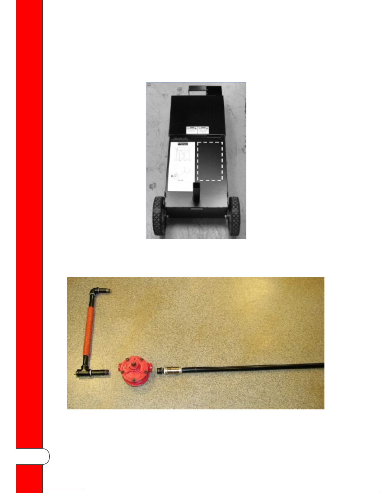
22..11..22 AAppppllyy LLaabbeell
Obtain the sheet of warning labels, and then choose your preferred language. Apply
the label to the ODS drain pan in the area marked by the dotted lines.
22..11..33 PPrreeppaarree CCoonnnneeccttiioonnss
Clean the threads, and then apply thread tape or sealant to connections.
Assembly
4
Page 11
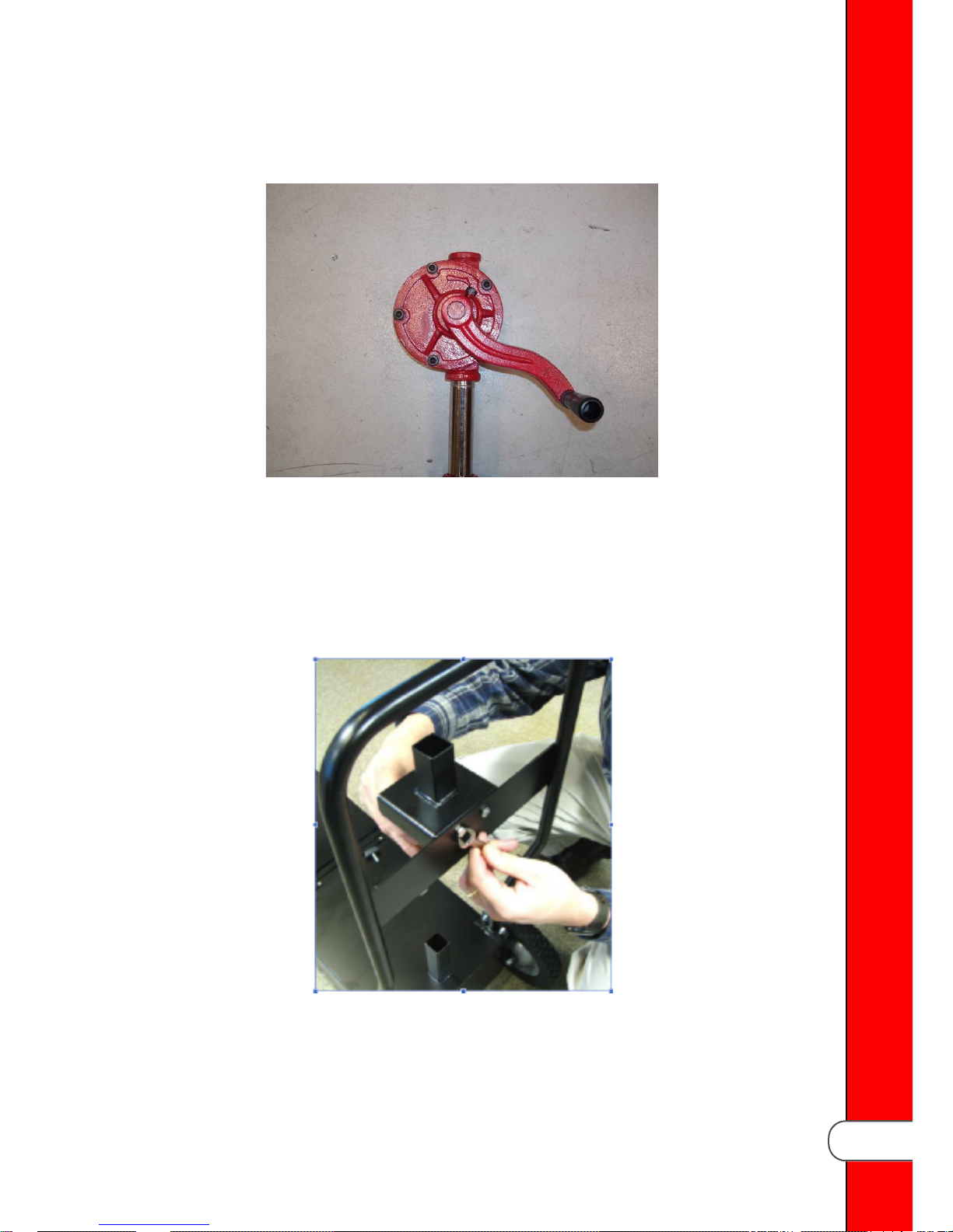
22..11..44 AAttttaacchh HHaannddllee
Attach the pump handle.
22..11..55 AAttttaacchh HHaannddllee BBrraacckkeett
Do the following:
11)) Bolt the down-pipe retaining bracket to the handle using the supplied hardware.
22)) Slide the pump and tube through the center square in the retaining bracket.
33)) Fit the end of the down-pipe into the round tube on the drain pan.
Assembly
5
Page 12
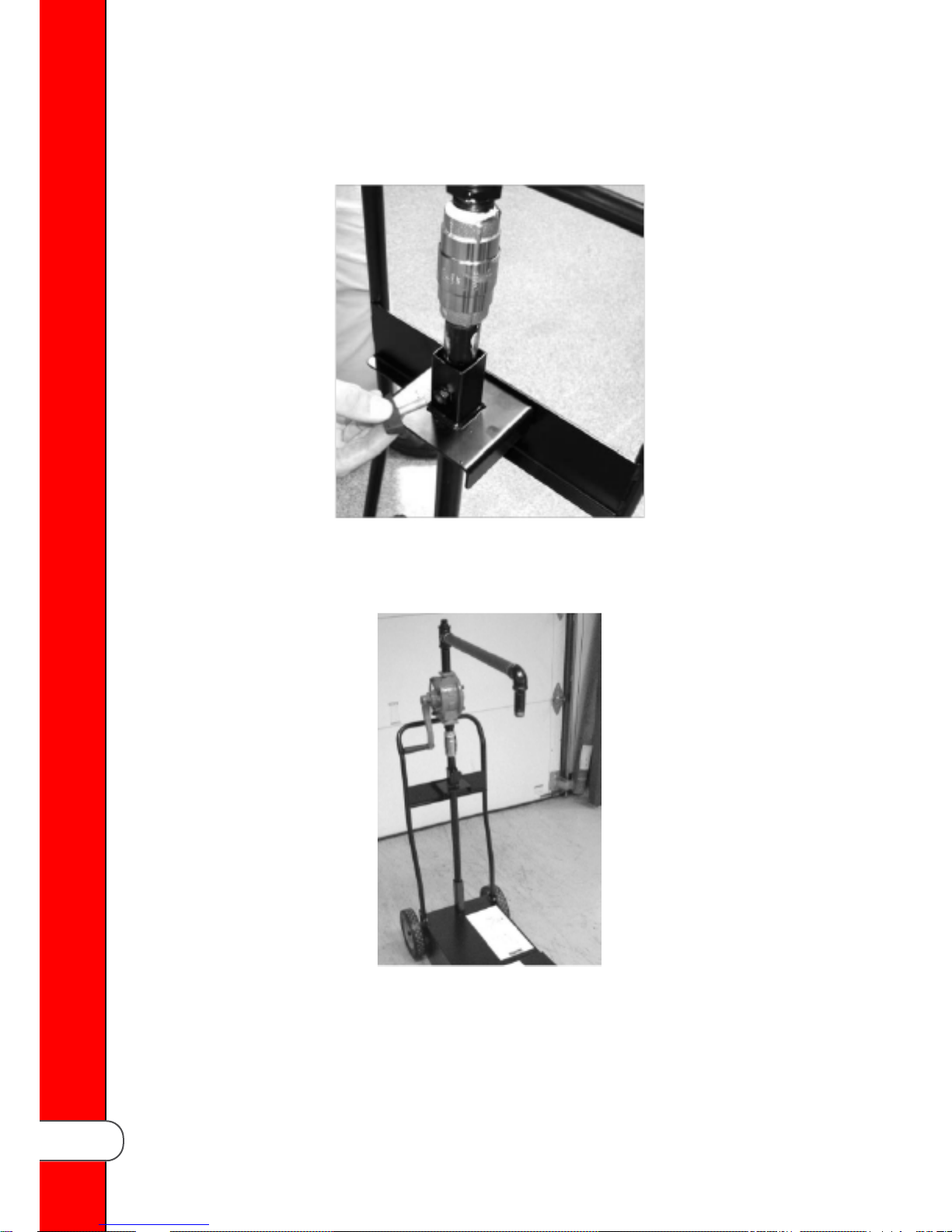
22..11..66 AAttttaacchh DDoowwnn PPiippee
Insert thumb screw through the retaining bracket and secure the down tube.
22..11..77 AAttttaacchh DDrraaiinn PPiippee
Attach the drain-pipe assembly to the top of the pump assembly, and then tighten and
align as shown.
Assembly
6
Page 13
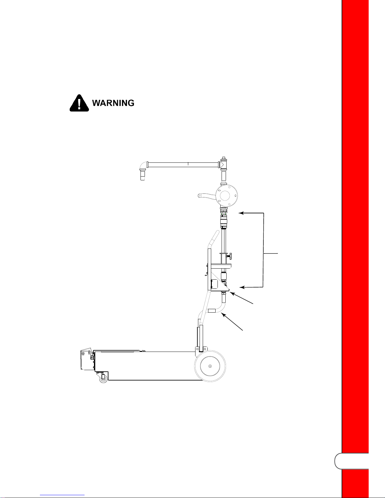
22..22 MMooddeell 331100
172505
173056
173055
The assembly process is the same as the model 300 with the following exceptions.
The identified parts are different and require additional installation steps.
IINNFFOO:
HHeeaavvyy oobbjjeecctt!! SSeeee tthhee ttaabbllee iinn 11..44
aanndd WWeeiigghhttss
,, ppaaggee 11 ffoorr tthhee wweeiigghhtt.. TTaakkee ccaarree
DDiimmeennssiioonnss
wwhheenn mmoovviinngg tthhee sshhuuttttllee ccoommppoonneennttss ttoo pprreevveenntt
ppeerrssoonnaall iinnjjuurryy..
AAnnyy sshhiippppiinngg ddaammaaggee sshhoouulldd bbee nnootteedd iinn tthhee
pprreesseennccee ooff tthhee ddeelliivveerryy aaggeenntt aanndd ssiiggnneedd pprriioorr ttoo
hhiiss oorr hheerr ddeeppaarrttuurree..
11)) Install the stand pipe bracket to the handle using supplied hardware.
22)) Install the upper stand-pipe to and through the top of the stand pipe bracket.
33)) Install the lower flexible stand-pipe to and through the bottom of the stand pipe
bracket.
44)) Install the hand pump to the top of the stand pipe.
Assembly
7
Page 14

Assembly
8
Page 15
CChhaapptteerr 33 BBaassiicc OOppeerraattiioonn
BBuurrnn rriisskk!! AAllwwaayyss wweeaarr PPeerrssoonnaall PPrrootteeccttiivvee EEqquuiippmmeenntt
((PPPPEE)) wwhheenn uussiinngg aann OOiill DDiissppoossaall SShhuuttttllee ((OODDSS))..
PPeerrssoonnaall iinnjjuurryy oorr sseerriioouuss bbuurrnnss ccaann rreessuulltt ffrroomm ssppllaasshhiinngg
hhoott ooiill..
• DDoo nnoott oovveerrffiillll.. SShhuuttttllee hhoollddss ooiill ffrroomm oonnee ffuullll ssiizzee ffrryy ppoott
oorr ttwwoo sspplliitt vvaattss.. OOvveerrffiilllliinngg ccaann ccaauussee ppeerrssoonnaall iinnjjuurryy oorr
ddaammaaggee ttoo eeqquuiippmmeenntt..
• FFiillll wwiitthh sshhoorrtteenniinngg oonnllyy.. DDoo nnoott ppuutt wwaatteerr aanndd//oorr cclleeaanneerr
iinnssiiddee tthhee sshhuuttttllee.. MMiixxiinngg wwaatteerr wwiitthh hhoott ooiill ccaann ccaauussee
ssppllaatttteerriinngg,, wwhhiicchh ccaann lleeaadd ttoo ppeerrssoonnaall iinnjjuurryy.. WWaatteerr aanndd
cclleeaanneerr ccaann ccaauussee ccoorrrroossiioonn aanndd ddaammaaggee ttoo tthhee ppuummpp..
• DDoo nnoott ttrraannssppoorrtt ooiill wwiitthhoouutt ccoovveerr iinn ppllaaccee.. SSppllaasshhiinngg ooiill
ccaann ccaauussee ppeerrssoonnaall iinnjjuurryy..
The basic operation of the ODS 300 / 310 are the same.
33..11 SShhuuttttllee SSeettttiinngg
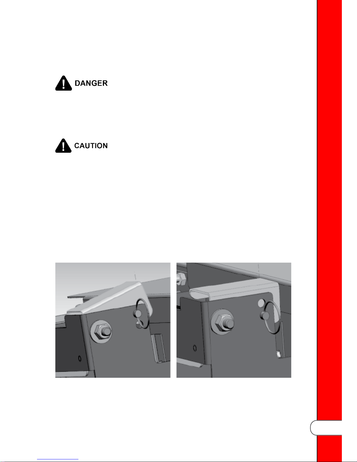
The shuttle works with multiple fryer models. Adjust the shuttle accordingly.
For the LVE1XX, LVG1XX, EEE1XX,
EEG1XX model fryers.
For the LVE2XX, LVG2XX, EEG2XX and F5
OFE5XX, OFG5XX and FFE5XX model
fryers.
Basic Operation
9
Page 16
33..22 SShhuuttttllee PPoossiittiioonn
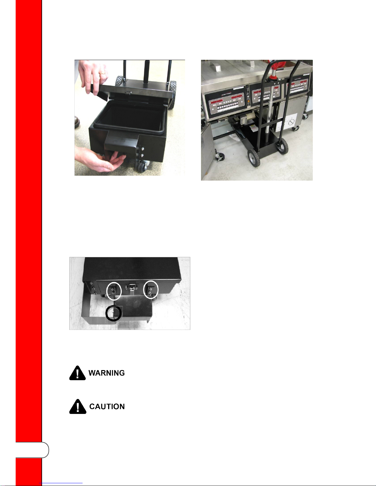
11)) Release cover latch and hinge cover back on oil disposal shuttle. Make sure
crumb catcher is in place.
22)) Remove the filter drain pan assembly from under the fryer, and then roll the oil
disposal shuttle under fryer until it stops. Make sure the fryer’s drain aligns with
opening in shuttle.
33)) Perform the drain procedures from the operation manual for your model of fryer.
33..33 OOiill DDiissppoossaall
Basic Operation
On LVE / LVG-10X fryers, if oil disposal
shuttle is not properly in place, “IS
DISPOSAL UNIT IN PLACE?” displays.
Adjust center bracket on the front of
shuttle as needed by loosening the 6
nuts holding bracket and moving the
bracket up or down. Once properly
adjusted, the control displays
“DISPOSING”.
TToo aavvooiidd bbuurrnnss aanndd ppeerrssoonnaall iinnjjuurryy,, aallllooww ooiill ttoo ccooooll ttoo
110000°° FF ((3388°° CC)) oorr bbeellooww bbeeffoorree ttrraannssppoorrttiinngg sshhuuttttllee ttoo tthhee
ddiissppoossaall aarreeaa..
To avoid damage to the pump:
• Only pump oil at 100° F (38° C) or below.
• Do not pump water or water-based liquids.
10
Page 17
11)) Remove the oil disposal shuttle from under the fryer and replace with the filter
pan assembly.
22)) Replace and latch the cover and roll oil disposal shuttle to disposal container.
33)) Turn the thumb screw on the bracket to loosen pump assembly.
44)) Swivel the pump assembly over the disposal container, and then tighten the
thumb screw on the bracket.
55)) Turn the pump handle rapidly (fast) in order to prime the pump and to get oil to
flow through pump.
66)) Once the shuttle is empty, loosen the thumb screw on the bracket, and swivel
the pump assembly back over the lower unit and tighten the handle.
33..44 AAdddd OOiill
Follow the oil fill procedures from the operation manual for your model of fryer, and
then return the fryer to normal operation.
33..55 CClleeaanniinngg tthhee OODDSS
DDoo nnoott ppuutt wwaatteerr aanndd//oorr cclleeaanneerr iinnssiiddee tthhee sshhuuttttllee.. MMiixxiinngg
wwaatteerr wwiitthh hhoott ooiill ccaann ccaauussee ssppllaatttteerriinngg,, wwhhiicchh ccaann lleeaadd ttoo
ppeerrssoonnaall iinnjjuurryy.. WWaatteerr aanndd cclleeaanneerr ccaann ccaauussee ccoorrrroossiioonn
aanndd ddaammaaggee ttoo tthhee ppuummpp..
Daily, remove the crumb catcher and take it to a sink and clean with soap and water.
Clean the exterior of the shuttle with a soft cloth and soap and water. It’s not
necessary to clean the interior of the unit, but if desired it can be wiped down with
paper towels.
Basic Operation
11
Page 18

Basic Operation
12
Page 19
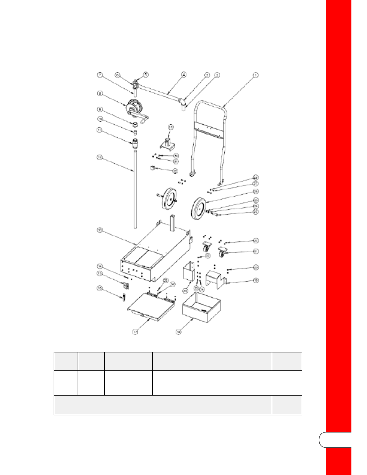
CChhaapptteerr 44 MMooddeell 330000 PPaarrttss
Item Stock
Level
1 84368 HANDLE, DRAIN PAN 1
2 FP02-021 NIPPLE, 3/4” X 3 1
RReeccoommmmeenndd PPaarrttss:: AA == TTrruucckk SSttoocckk // BB == DDiisstt.. SSttoocckk
** == NNoott SShhoowwnn // AARR == AAss RReeqquuiirreedd
Part No. Description Qty.
TTaabbllee 44--11 MMooddeell 330000 OODDSS
Model 300 Parts
13
Page 20

Item Stock
Level
3 FP01-098 ELBOW, 3/4” X 90 FEMALE 1
4 FP02-056 NIPPLE, 3/4” X 18.25 1
5 FP01-140 PLUG, PIPE 3/4” 1
6 FP01-097 TEE, PIPE 3/4” 1
7 FP02-033 NIPPLE, 3/4” X 4 1
8 A 72490 PUMP, MANUAL OIL DISCARD 1
9 FP01-227 REDUCER, 1” MALE TO 3/4” FEMALE 1
10 16282 NIPPLE, 3/4” CLOSE 1
11 A 21800 VALVE, 3/4” CHECK 1
12 84376 PIPE, 3/4” BLACK 1
13 N/A NOT ORDERABLE N/A
14 NS02-005 NUT, KEPS 6 X 32 2
15 83994 BRKT, MOUNTING HINGE 1
Part No. Description Qty.
16 A MS01-532 LATCH, BREADING MACHINE DRUM 1
17 B 84001 COVER, LVE DRAIN PAN DOLLY 1
18 B 84453 BASKET, CRUMB BASKET 1
19 B 84519 SWITCH, DRAIN 1
20 NS02-006 NUT, 10 X 24 HEX HD 4
21 B 19004 CASTER, 2” SWIVEL 1
22 NS02-006 NUT, KEPS 10 X 24 8
23 B SC06-074 SCREW, 1/2” X 1” X 1/2” SHOULDER 3/8”
X 16
24 LW01-010 LOCKWASHER, SPLIT-RING 3/8” 2
25 NS01-001 NUT, 3/8” X 16 HEX HD 2
26 B 77815 WHEEL, 8” 2
27 B SC01-057 SCREW, 1/4” X 20 X 1/2” HEX HD 4
28 NS02-002 NUT, KEPS 1/4” X 20 4
29 84481 LOCKNUT & PUMP 1
2
RReeccoommmmeenndd PPaarrttss:: AA == TTrruucckk SSttoocckk // BB == DDiisstt.. SSttoocckk
Model 300 Parts
** == NNoott SShhoowwnn // AARR == AAss RReeqquuiirreedd
14
Page 21
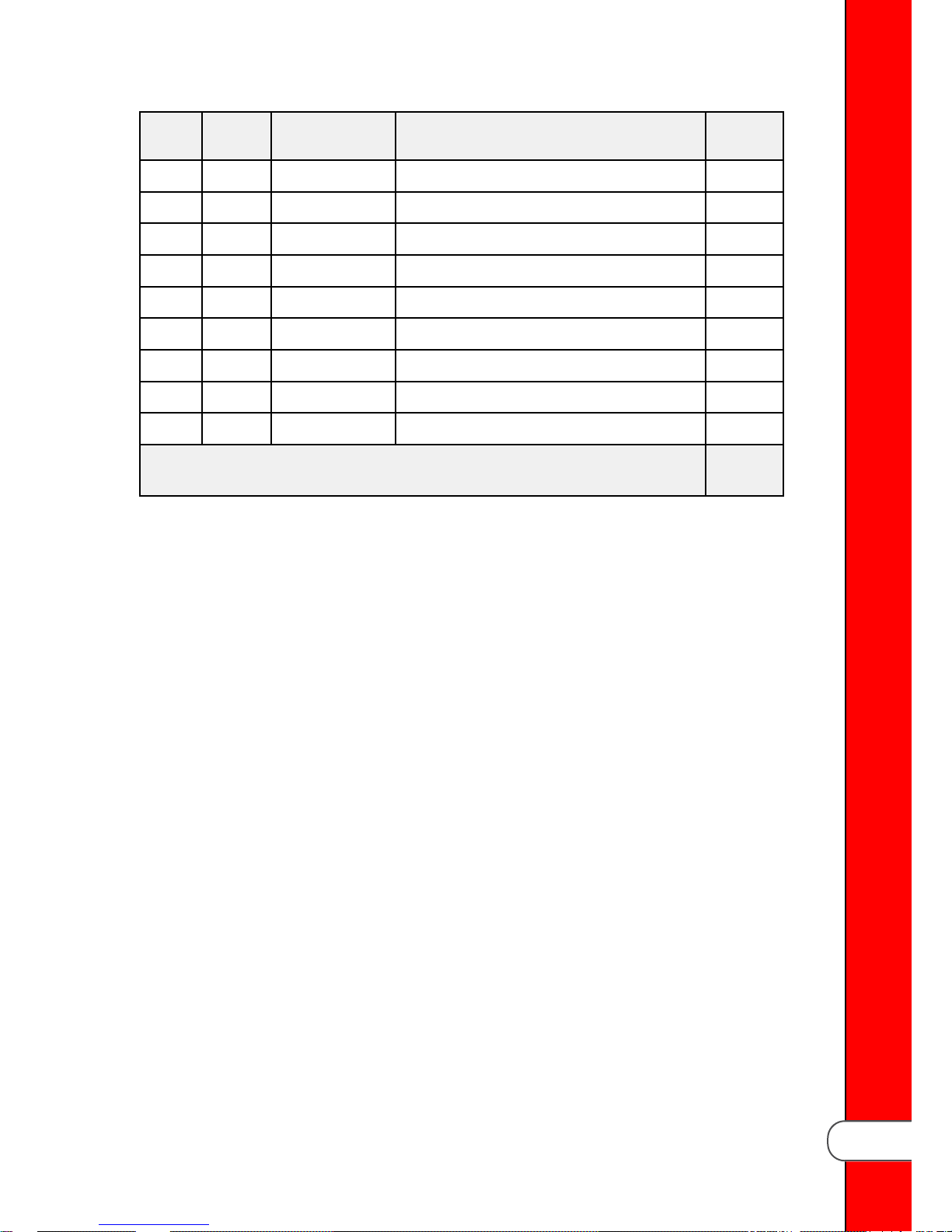
Item Stock
Level
30 SC01-057 SCREW, 1/4” X 20 X 1/2” HEX HD 2
31 NS02-002 NUT, KEPS 1/4” X 20 2
32 SC06-076 SCREW, THUMB 8 X 25 BLK KNOB 1
33 NS02-006 NUT, KEPS 10 X 24 HEX HD 3
34 SC01-038 SCREW, 10 X 24 X 3/8” PH THD S 3
35 NS02-006 NUT, KEPS 10 X 24 HEX HD 3
36 88527 BRACKET, DRAIN SWITCH 1
37 B SC01-113 SCREW, 6 X 32 X 9/16” PHILLIPS 4
38 B NS02-005 NUT, KEPS 6 X 32 HEX 4
RReeccoommmmeenndd PPaarrttss:: AA == TTrruucckk SSttoocckk // BB == DDiisstt.. SSttoocckk
** == NNoott SShhoowwnn // AARR == AAss RReeqquuiirreedd
Part No. Description Qty.
Model 300 Parts
15
Page 22

Model 300 Parts
16
Page 23
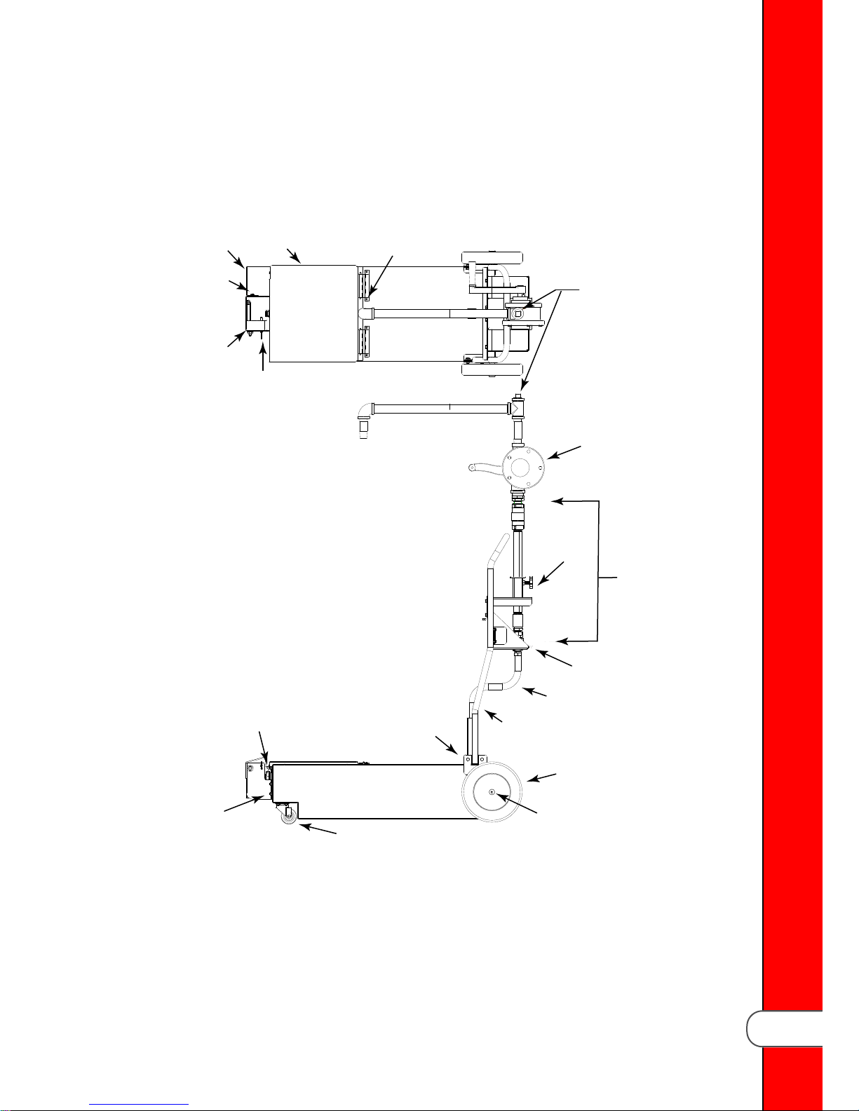
CChhaapptteerr 55 MMooddeell 331100 PPaarrttss
173055
SC01-057
NS02-002
SC06-076
NS02-002
SC01-057
NS02-005
163805
NS02-006
163795
163837
SC01-113
84383
72490
83994
89041
19004
172505
173056
84368
77815
SC06-074
The model 300 is upgraded to the model 310 using a kit. Many of the 300 parts fit on
the 310. The main differences are the drain pan switch, down-pipe (stand-pipe)
assembly and the lower suction tube, which is a curved molded flexible pipe.
Model 310 Parts
17
Page 24

TTaabbllee 55--11 MMooddeell 331100 OODDSS
Part No. Stock
Level
140638 B KIT, RETRO FIT(Model 300 to 310) 1
163795 BRACKET, SWITCH RETROFIT DRAIN 1
163805 B DRAIN SWITCH, ASSY RETROFIT DRAIN 1
163837 B COVER, DRAIN PAN 1
172505 BRACKET, DOWN-PIPE HOLD 1
173055 DOWN-PIPE (STAND-PIPE), ASSY. 1
173056 B TUBE, SUCTION 1
19004 B CASTER, 2 INCH FRONT 2
72490 B PUMP, MANUAL OIL DISCARD 1
77815 B WHEEL, 8 INCH REAR 2
83994 BRKT, HINGE MOUNTING 1
84368 HANDLE, ASSY. DRAIN 1
84383 DRAIN-PIPE, ASSY. 1
Description Qty.
LW01-010 LOCKWASHER, SPLIT RING 3/8” ID 2
NS01-001 NUT, 3/8” X 16 HEX 2
NS02-002 NUT, KEPS 1/4” X 20 8
NS02-005 NUT, KEPS 6 X 32 HEX 8
NS02-006 NUT, KEPS 10 X 24 HEX 18
SC01-057 SCREW, 1/4” X 20 X 1/2” HEX 8
SC01-113 SCREW, 6 X 32 X 9/16” 4
SC03-001 SCREW, 10 X 1/2” 4
SC06-074 SCREW, 3/16” X 1/2” X 1 1/2” 2
SC06-076 SCREW, THUMB 8 X 25 BLK KNOB 1
RReeccoommmmeenndd PPaarrttss:: AA == TTrruucckk SSttoocckk // BB == DDiisstt.. SSttoocckk
** == NNoott SShhoowwnn // AARR == AAss RReeqquuiirreedd
Model 310 Parts
18
Page 25
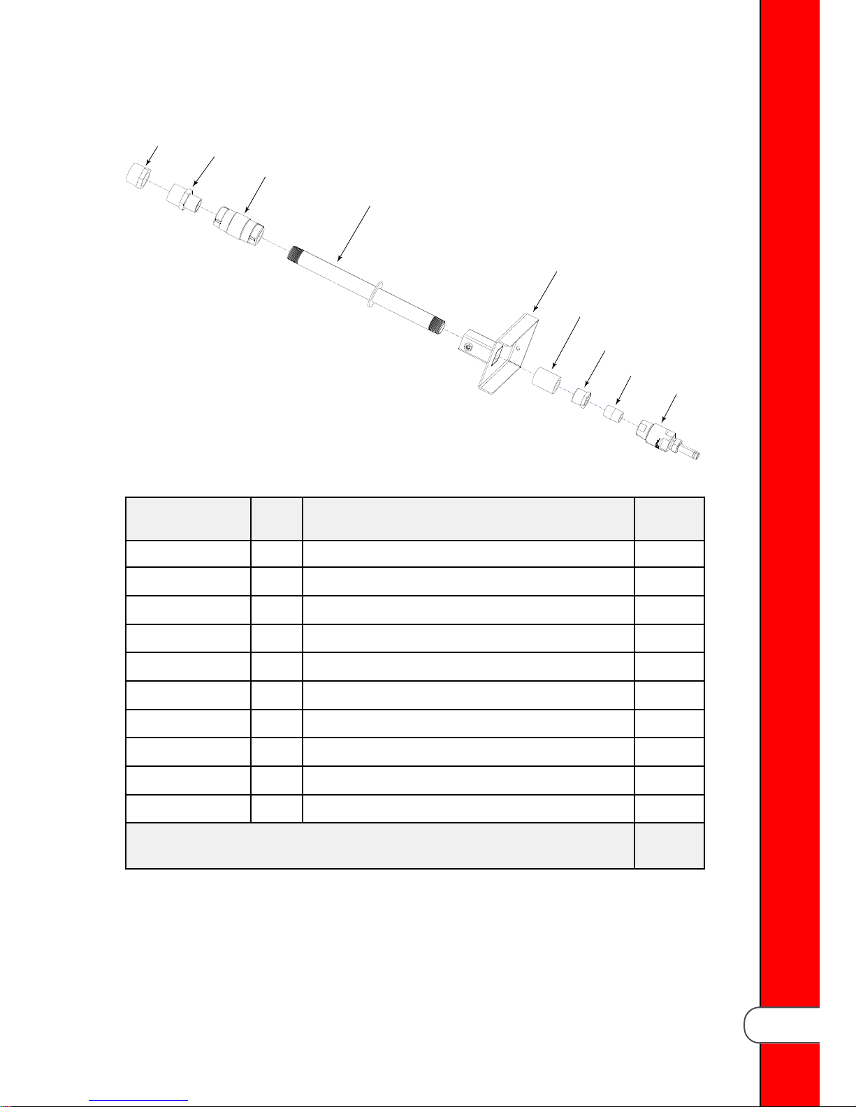
55..11 UUppppeerr SSttaanndd--PPiippee AAsssseemmbbllyy
FP01-227
FP01-298
21800
172472
172441
FP01-221
FP01-089
FP01-023
172576
TTaabbllee 55--22 MMooddeell 331100 UUppppeerr SSttaanndd PPiippee
Part No. Stock
Level
173055 DOWN-PIPE ASSY. 1
172441 - BRACKET, TUBE 1
172472 - TUBE, STOP 1
172576 - SWIVEL, 1/2” NPT 1
21800 - VALVE, CHECK 3/4” 1
FP01-023 - NIPPLE, 1/2” 1
FP01-089 - BUSHING, REDUCING 3/4” X 1/2” 1
FP01-221 - COUPLING, 3/4” HOSE 1
FP01-227 - COUPLING, 1” MALE TO 3/4” FEMALE 1
FP01-298 - COUPLING, 1” MALE TO 3/4” FEMALE 1
RReeccoommmmeenndd PPaarrttss:: AA == TTrruucckk SSttoocckk // BB == DDiisstt.. SSttoocckk
** == NNoott SShhoowwnn // AARR == AAss RReeqquuiirreedd
Description Qty.
Model 310 Parts
19
Page 26
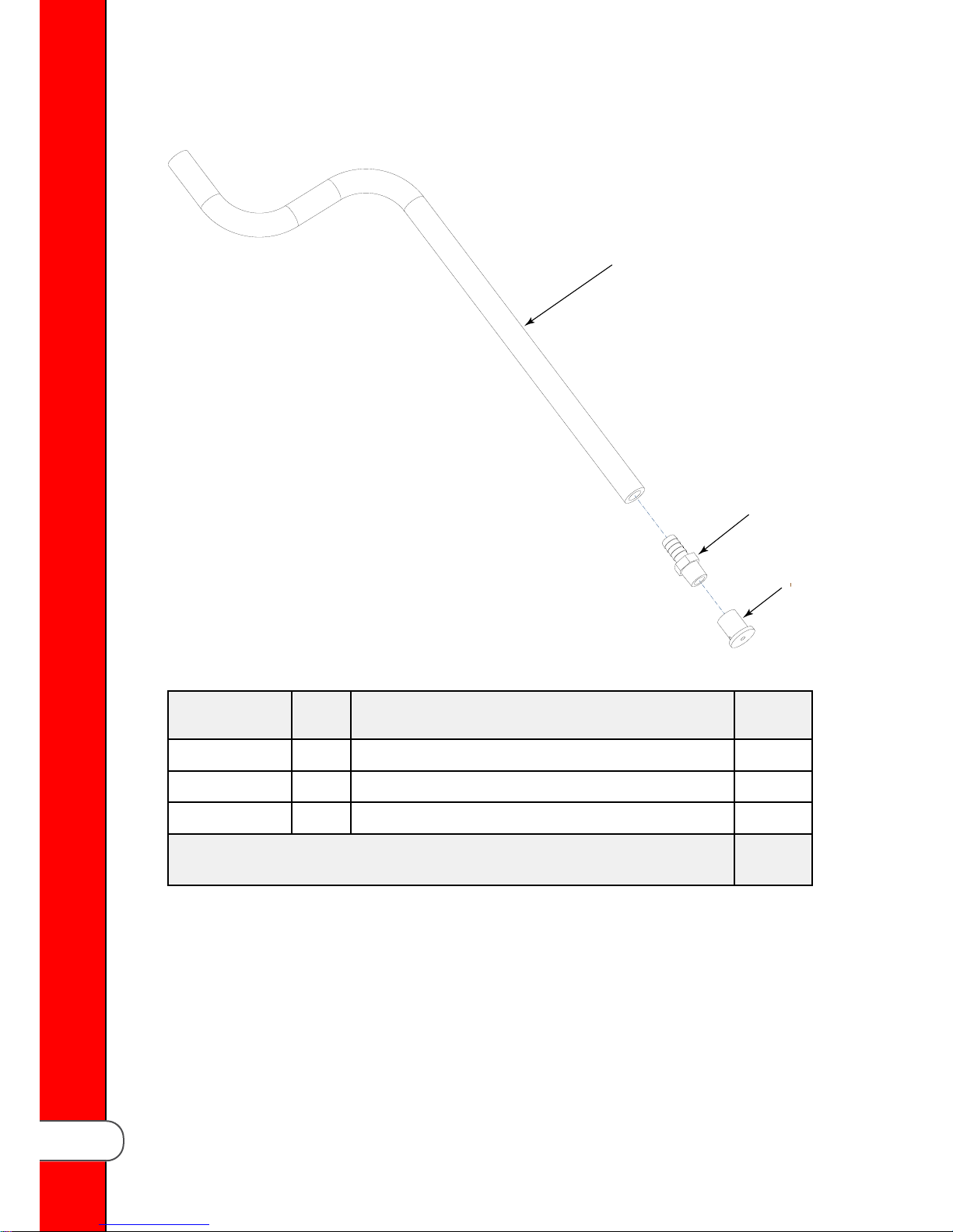
55..22 LLoowweerr FFlleexxiibbllee SSttaanndd--PPiippee AAsssseemmbbllyy
162238-509
FP01-228
161399
Model 310 Parts
TTaabbllee 55--33 MMooddeell 331100 LLoowweerr FFlleexxiibbllee SSttaanndd PPiippee
Part No. Stock
Level
161399 PICKUP, JIB 1
162239–230 A HOSE, FLEXIBLE FORMED 1
FP01–228 BARB, 1/2 X 3/8 NYLON 1
RReeccoommmmeenndd PPaarrttss:: AA == TTrruucckk SSttoocckk // BB == DDiisstt.. SSttoocckk
** == NNoott SShhoowwnn // AARR == AAss RReeqquuiirreedd
Description Qty.
20
Page 27

CChhaapptteerr 66 AAcccceessssoorriieess
This section identifies and lists the accessories available from your distributor.
66..11 FFiilltteerr HHoossee
An optional filter disposal hose is available.
Item Part No. Description
* 03616 KIT, FILTER HOSE ACCESSORY
1 81066 HOSE, FILTER
2 85135 BRACKET, HOLDER
* = Not Shown
TTaabbllee 66--11 FFrryyeerr AAcccceessssoorriieess
Accessories
21
Page 28

Item Part No. Description
3 80995 HOLDER, FILTER HOSE
4 SC06–013 U-BOLTS
* NS02–002 NUTS
* = Not Shown
Accessories
22
Page 29

blank page
Page 30

HHeennnnyy PPeennnnyy CCoorrppoorraattiioonn
PP..OO..BBooxx 6600
EEaattoonn,, OOHH 4455332200
wwwwww..hheennnnyyppeennnnyy..ccoomm
IInnssiiddee tthhee UU..SS..::
11--880000--441177--88440055
tteecchhnniiccaallsseerrvviicceess@@hheennnnyyppeennnnyy..ccoomm
OOuuttssiiddee tthhee UU..SS..
11--993377--445566--88440055
iinnttlltteecchhssuuppppoorrtt@@hheennnnyyppeennnnyy..ccoomm
 Loading...