

Page 1
SECTION 2. INSTALLATION
Model HMR-103,104,105,106,107
2-1. INTRODUCTION
2-2. UNPACKING
This section provides the installation instructions for the Henny
Penny Heated Merchandiser.
Installation of this unit should be performed only by a qualified
service technician.
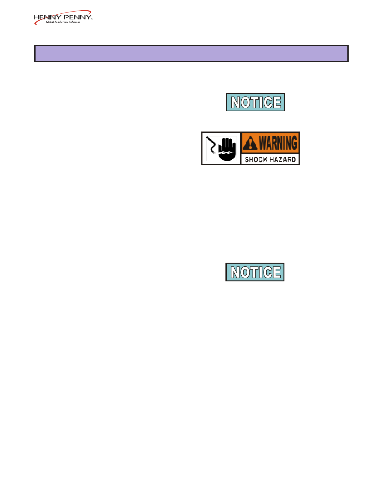
Do not puncture the heated merchandiser with any objects
such as drills or screws as component damage or electrical
shock could result.
The Henny Penny Heated Merchandiser is tested, inspected and
expertly packed to ensure arrival at its destination in the best possible
condition. The unit has been bolted to wooden skid. All items have
been packed and taped inside of the unit. The unit is then packed
inside a triple wall corrugated carton with sufficient padding to withstand normal shipping treatment.
Any shipping damage should be noted in the presence of the
delivery agent and signed prior to his or her departure.
To remove the heated merchandiser from the carton, you should:
1. Carefully cut banding straps.
2. Open flaps of carton and remove packing.
3. Lift carton from unit.
4. Remove four bolts mounting the merchandiser to the skid.
5. If installing the unit on a merchandiser base, use existing bolts to
mount unit.
6. Unpack doors, cutting board, and pan supports, and install.
7. The heated merchandiser is now ready for location and setup.
203 2-1
Page 2
Model HMR-103,104,105,106,107
2-3. ELECTRICAL
CONNECTION
NEMA NUMBERS:
Model 208/240-1 ph 208-3 ph 240-3 ph
10 7 14-50P L21-30P Hardwire
10 6 14-50P L21-30P Hardwire
10 5 14-50P L21-30P Hardwire
104 L14-30P L21-20P Hardwire
103 L14-30P L21-20P Hardwire
The heated merchandiser is available from the factory, wired for
120/208-240 volts, single or three phase, (includes neutral), 220-240
volts, or 380-415 volts. Refer to the table at left, and bottom, for proper
power connection.
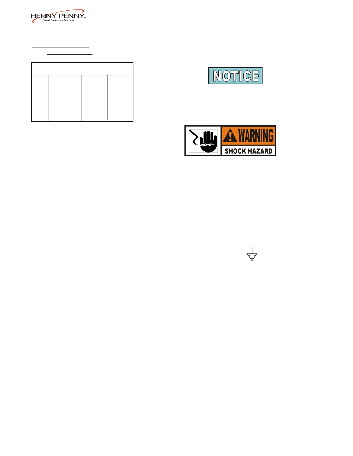
International units are not supplied with cord and plug, and
must be provided upon installation. If two CE units are
placed side-by-side, a grounding wire needs to be placed
between the equipotential bonding lugs, located under the
cutting board brackets, of both units.
This unit must be adequately and safely grounded. Refer to
local electrical codes for correct grounding procedures. If
heated merchandiser is not adequately grounded, electrical
shock could result.
(FOR EQUIPMENT WITH CE MARK ONL Y!)
T o prevent electric shock hazard this appliance must be
bonded to other appliances or touchable metal surfaces in
close proximity to this appliance with an equipotential
bonding conductor . This appliance is equipped with an
equipotential lug for this purpose. The equipotential lug is
marked with the following symbol
A separate disconnect switch with proper capacity fuses or breakers
must be installed at a convenient location between the unit and the
power source.
2-2 1004
Page 3

Model HMR-103,104,105,106,107
2-4. ELECTRICAL DATA TABLE
COMBI- AMPS COMBI- AMPS
MODEL NATION VOLTS KW 1 PHASE 3 PHASE MODEL NATION VOLTS KW 1 PHASE 3 PHASE
HMR-107 7S 120/208 5.0 24 18 HMR-107 3F/2S/2F* 120/208 6.0 29 19
6.7 32 22 7.8 37 23
120/240 5.0 16 16 120/240 6.0 25 17
7.0 29 20 8.1 34 21
220-240 5.4 22 N/A 220-240 6.4 27 N/A
7.5 31 N/A 8.5 36 N/A
380-415 5.4 N/A 11 380-415 6.4 N/A 11
7.5 N/A 11 8.5 N/A 13
HMR-107 7F 120/208 6.0 29 19 HMR-107 2S/3F/2S 120/208 5.5 27 19
7.8 37 23 7.3 35 22
120/240 6.0 25 17 120/240 5.5 23 16
8.1 34 21 7.6 32 20
220-240 6.4 27 N/A 220-240 6.0 25 N/A
8.5 36 N/A 8.0 33 N/A
380-415 6.4 N/A 11 380-415 6.0 N/A 11
8.5 N/A 13 8.0 N/A 12
HMR-107 5S/2F* 120/208 5.5 26 18 HMR-107 2F/3S/2F 120/208 5.9 29 19
7.2 35 22 7.7 37 22
120/240 5.5 23 16 120/240 5.9 25 16
7.5 31 20 8.0 33 20
220-240 5.9 24 N/A 220-240 6.4 27 N/A
7.9 33 N/A 8.4 35 N/A
380-415 5.9 N/A 11 380-415 6.4 N/A 11
7.9 N/A 12 8.4 N/A 12
HMR-107 5F/2S* 120/208 5.5 27 19 HMR-106 6S 120/208 4.0 19 13
7.3 35 22 5.5 26 16
120/240 5.5 23 16 120/240 4.0 17 12
7.3 30 20 5.7 24 15
220-240 6.0 25 N/A 220-240 4.3 18 N/A
8.0 33 N/A 6.1 25 N/A
380-415 6.0 N/A 11 380-415 4.3 N/A 8
8.0 N/A 12 6.1 N/A 9
HMR-107 4S/3F* 120/208 5.5 27 19 HMR-106 6F 120/208 5.0 24 15
7.3 35 22 6.5 31 20
120/240 5.5 23 16 120/240 5.0 21 13
7.6 32 21 6.8 28 18
220-240 6.0 25 N/A 220-240 5.4 22 N/A
8.0 33 N/A 7.2 30 N/A
380-415 6.0 N/A 11 380-415 5.4 N/A 8
8.0 N/A 12 7.2 N/A 12
HMR-107 4F/3S* 120/208 5.5 27 19 HMR-106 4S/2F* 120/208 4.5 21 14
7.3 35 22 6.0 29 17
120/240 5.5 23 16 120/240 4.5 19 12
7.6 32 20 6.2 26 16
220-240 6.0 25 N/A 220-240 4.8 20 N/A
8.0 33 N/A 6.6 27 N/A
380-415 6.0 N/A 11 380-415 4.8 N/A 8
8.0 N/A 12 6.6 N/A 10
HMR-107 3S/2F/2S* 120/208 5.5 27 18 HMR-106 4F/2S* 120/208 4.5 22 14
7.2 35 22 6.0 29 17
120/240 5.5 23 16 120/240 4.5 19 12
7.5 31 20 6.3 26 16
220-240 5.9 24 N/A 220-240 4.9 20 N/A
7.9 33 N/A 6.7 28 N/A
380-415 5.9 N/A 11 380-415 4.9 N/A 8
7.9 N/A 12 6.7 N/A 10
*Well modules can be arranged in opposite order
703 2-3
Page 4

Model HMR-103,104,105,106,107
2-4. ELECTRICAL DATA TABLE (Continued)
COMBI- AMPS COMBI- AMPS
MODEL NATION VOLTS KW 1 PHASE 3 PHASE MODEL NATION VOLTS KW 1 PHASE 3 PHASE
HMR-106 3S/2F* 120/208 5.2 25 17 HMR-105 3F/2S* 120/208 4.2 20 14
(Cont.) 6.7 32 20 (Cont.) 5.5 26 17
120/240 5.2 22 15 120/240 4.2 18 12
7.0 29 18 5.7 24 15
220-240 5.5 23 N/A 220-240 4.5 19 N/A
7.3 31 N/A 6.0 25 N/A
380-415 5.5 N/A 11 380-415 4.5 N/A 8
7.3 N/A 11 6.0 N/A 9
HMR-106 2S/2F/2S 120/208 4.5 21 14 HMR-104 4S 120/208 2.6 13 9
6.0 29 17 3.6 17 11
120/240 4.5 19 12 120/240 2.6 11 8
6.2 26 16 3.8 16 10
220-240 4.8 20 N/A 220-240 2.8 12 N/A
6.6 27 N/A 4.0 17 N/A
380-415 4.8 N/A 8 380-415 2.8 N/A 5
6.6 N/A 10 4.0 N/A 6
HMR-106 2F/2S/2F 120/208 4.9 24 14 HMR-104 4F 120/208 3.2 15 9
6.4 31 19 4.2 20 12
120/240 4.9 21 13 120/240 3.2 13 8
6.7 28 18 4.4 18 12
220-240 5.3 22 N/A 220-240 3.4 14 N/A
7.1 30 N/A 4.6 19 N/A
380-415 5.3 N/A 8 380-415 3.4 N/A 5
7.1 N/A 12 4.6 N/A 7
HMR-105 5S 120/208 3.6 18 13 HMR-104 2S/2F* 120/208 3.1 15 9
4.9 24 16 4.1 20 12
120/240 3.6 15 12 120/240 3.1 13 8
5.1 21 15 4.3 18 11
220-240 3.9 16 N/A 220-240 3.3 14 N/A
5.4 23 N/A 4.5 19 N/A
380-415 3.9 N/A 8 380-415 3.3 N/A 5
5.4 N/A 8 4.5 N/A 7
HMR-105 5F 120/208 4.2 20 14 HMR-103 3S 120/208 2.3 11 9
5.5 26 17 3.0 15 11
120/240 4.2 18 12 120/240 2.3 10 8
5.7 24 15 3.2 13 10
220-240 4.5 19 N/A 220-240 2.4 10 N/A
6.0 25 N/A 3.4 14 N/A
380-415 4.5 N/A 8 230 2.4 11 N/A
6.0 N/A 9 380-415 2.4 N/A 5
HMR-105 3S/2F* 120/208 4.1 20 14 3.2 N/A 5
5.4 26 17 HMR-103 3F 120/208 2.8 14 9
120/240 4.3 18 13 3.6 17 11
5.6 23 15 120/240 2.8 12 8
220-240 4.4 18 N/A 3.7 16 10
5.9 25 N/A 220-240 3.0 12 N/A
380-415 4.4 N/A 8 3.9 16 N/A
5.9 N/A 9 230 3.0 13 N/A
380-415 3.0 N/A 5
3.9 N/A 6
*Well modules can be arranged in opposite order
2-4 703
Page 5

2-5. CABINET DIMENSIONS
Model HMR-103,104,105,106,107
803 2-5
Page 6

Model HMR-103,104,105,106,107
2-6. CENTER GLASS These are the instructions for installing the center glass on units
INSTALLATION that are combination, self-serve and standard merchandisers.
1. Notice the location of the bracket on unit, as indicated.
2. Using a 3/8” socket, or nut driver, loosen the 2 acorn nuts
securing the bracket, but do not remove.
3. Slide bracket off from around the 2 acorn nuts.
2-6 1202
Page 7

2-6. CENTER GLASS
INSTALLATION
(Continued)
Model HMR-103,104,105,106,107
4. Place glass in divider track as shown.
5. Slide bracket onto glass and align to its original position
around the 2 acorn nuts.
6. Retighten the 2 acorn nuts.
1202 2-7
Page 8

Model HMR-103,104,105,106,107
2-7. SIDE GLASS Install the side panel glass, on both sides of the unit, as follows:
INSTALLATION
1. Pull out plunger on retainer and turn clockwise to lock open.
2. Slide the glass into the channel on the side rail, making sure the
glass seats into the groove on the upright.
Step 1
3. Align the hole in the glass with the plunger of the retainer.
Step 4
4. Turn the plunger of the retainer clockwise again, to lock and
release the plunger in place.
5. Installation is now complete.
2-8 1202
 Loading...