

Page 1

Henny Penny
Heated Merchandisers
Model HMR-103
Model HMR-104
Model HMR-105
Model HMR-106
Model HMR-107
OPERATOR’S MANUAL
Page 2

Page 3

Model HMR-103,104,105,106,107
LIMITED WARRANTY FOR HENNY PENNY EQUIPMENT
Subject to the following conditions, Henny Penny Corporation makes the following limited warranties to the original
purchaser only for Henny Penny appliances and replacement parts:
NEW EQUIPMENT: Any part of a new appliance, except baskets, lamps, and fuses, which proves to be defective in
material or workmanship within two (2) years from date of original installation, will be repaired or replaced without
charge F .O.B. factory , Eaton, Ohio, or F .O.B. authorized distributor . Baskets will be repaired or replaced for ninety (90)
days from date of original installation. Lamps and fuses are not covered under this Limited W arranty. To validate this
warranty, the registration card for the appliance must be mailed to Henny Penny within ten (10) days after installation.
FILTER SYSTEM: Failure of any parts within a fryer filter system caused by the use of the non-OEM filters or
other unapproved filters is not covered under this Limited Warranty.
REPLACEMENT PARTS: Any appliance replacement part, except lamps and fuses, which proves to be defective in
material or workmanship within ninety (90) days from date of original installation will be repaired or replaced without
charge F .O.B. factory , Eaton, Ohio, or F .O.B. authorized distributor .
The warranty for new equipment covers the repair or replacement of the defective part and includes labor charges and
maximum mileage charges of 200 miles round trip for a period of one (1) year from the date of original installation.
The warranty for replacement parts covers only the repair or replacement of the defective part and does not include any
labor charges for the removal and installation of any parts, travel, or other expenses incidental to the repair or replacement of
a part.
EXTENDED FRYPOT WARRANTY: Henny Penny will replace any frypot that fails due to manufacturing or workmanship
issues for a period of up to seven (7) years from date of manufacture. This warranty shall not cover any frypot that fails due to
any misuse or abuse, such as heating of the frypot without shortening.
0 TO 3 YEARS: During this time, any frypot that fails due to manufacturing or workmanship issues will
be replaced at no charge for parts, labor, or freight. Henny Penny will either install a new frypot at no cost or
provide a new or reconditioned replacement fryer at no cost.
3 TO 7 YEARS: During this time, any frypot that fails due to manufacturing or workmanship issues will
be replaced at no charge for the frypot only . Any freight charges and labor costs to install the new frypot as
well as the cost of any other parts replaced, such as insulation, thermal sensors, high limits, fittings, and
hardware, will be the responsibility of the owner.
Any claim must be presented to either Henny Penny or the distributor from whom the appliance was purchased. No
allowance will be granted for repairs made by anyone else without Henny Penny’s written consent. If damage occurs during
shipping, notify the sender at once so that a claim may be filed.
THE ABOVE LIMITED WARRANTY SETS FOR TH THE SOLE REMEDY AGAINST HENNY PENNY FOR ANY BREACH
OF W ARRANTY OR OTHER TERM. BUYER AGREES THA T NO OTHER REMEDY (INCLUDING CLAIMS FOR ANY INCIDENT AL OR CONSEQUENTIAL DAMAGES) SHALL BE AV AILABLE.
The above limited warranty does not apply (a) to damage resulting from accident, alteration, misuse, or abuse; (b) if the
equipment’s serial number is removed or defaced; or (c) for lamps and fuses. THE ABOVE LIMITED WARRANTY IS EXPRESSL Y IN LIEU OF ALL OTHER W ARRANTIES, EXPRESS OR IMPLIED, INCLUDING MERCHANT ABILITY AND FITNESS, AND ALL OTHER W ARRANTIES ARE EXCLUDED. HENNY PENNY NEITHER ASSUMES NOR AUTHORIZES ANY
PERSON TO ASSUME FOR IT ANY OTHER OBLIGA TION OR LIABILITY.
Revised 01/01/07
FM05-013-E
Revised 02-15-07
Page 4

Model HMR-103,104,105,106,107
T ABLE OF CONTENTS
Section Page
Section 1. INTRODUCTION ....................................................................................................................1-1
1-1. Heated Merchandiser................................................................................................... 1-1
1-2. Features........................................................................................................................1-1
1-3. Assistance .................................................................................................................... 1-1
1-4. Safety ........................................................................................................................... 1-2
Section 2. INSTALLATION .....................................................................................................................2-1
2-1. Introduction ................................................................................................................. 2-1
2-2. Unpacking.................................................................................................................... 2-1
2-3. Electrical Connection .................................................................................................. 2-2
2-4. Electrical Data Table ................................................................................................... 2-3
2-5. Cabinet Dimensions ..................................................................................................... 2-5
2-6. Center Glass Installation .............................................................................................. 2-6
2-7. Side Glass Installation ..................................................................................................2-8
Section 3. OPERATION............................................................................................................................3-1
3-1. Introduction .................................................................................................................. 3-1
3-2. Start-Up .......................................................................................................................3-1
3-3. Operation with Product................................................................................................3-2
3-4. Shut Down and Clean Up ............................................................................................3-3
3-5. Light Bulb Replacement...............................................................................................3-5
3-6. Special Programming ................................................................................................... 3-6
Section 4. TROUBLESHOOTING ...........................................................................................................4-1
4-1. Troubleshooting Guide .................................................................................................. 4-1
4-2. Error Codes and Warnings........................................................................................... 4-1
GLOSSARY ............................................................................................................................. G-1
Distributors List - Domestic and International
i 1104
Page 5
SECTION 1. INTRODUCTION
Model HMR-103,104,105,106,107
1-1. HEA TED
MERCHANDISER
1-2. FEA TURES
The Henny Penny Heated Merchandiser is a basic unit of food
processing equipment used to display the food product and maintain
the temperature of hot foods in a commercial food service operation.
Using a combination of precise heat, humidity and slowly circulating
air, Henny Penny's even heat process creates the ideal environment to
maintain the taste and quality of freshly cooked foods for hours.
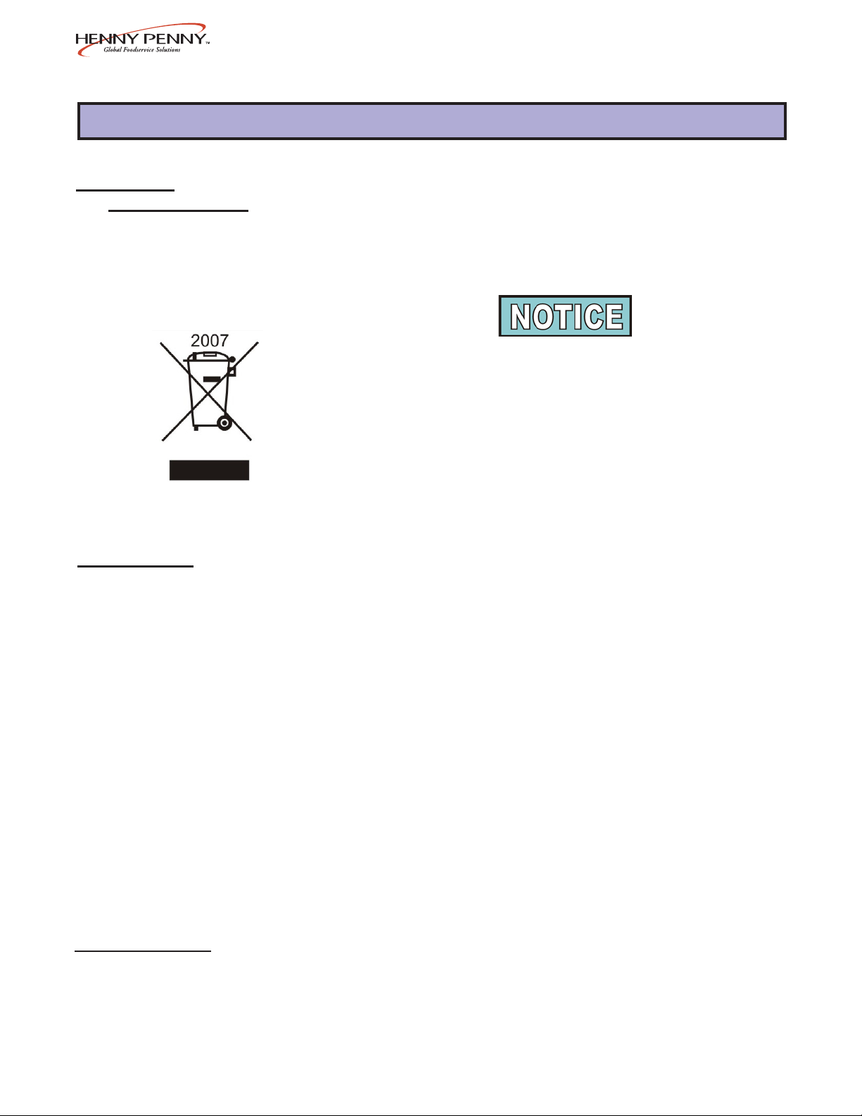
As of August 16, 2005, the W aste Electrical and Electronic
Equipment directive went into effect for the European Union.
Our products have been evaluated to the WEEE directive. W e
have also reviewed our products to determine if they comply
with the Restriction of Hazardous Substances directive (RoHS)
and have redesigned our products as needed in order to comply .
T o continue compliance with these directives, this unit must not be
disposed as unsorted municipal waste. For proper disposal,
please contact your nearest Henny Penny distributor .
• Unique THERMA-VEC
®
even heat process recirculates heated air,
keeping temperature precise and stable throughout the case
1-3. ASSISTANCE
• Contemporary curved glass cases present 100% product visibility
• Individually controlled radiant heaters over each well
• Ability to operate unit for up to an hour with the rear doors
removed while maintaining food temperature
• Humidity controlled with heated water pan
• T ouch pad electronic controls and LED readouts
• Halogen lighting for attractive food presentation
• Fold-down cutting board
• Low water indication
• Custom full/self serve units, in 2-well increments
• Separate controls above each well
Should you require outside assistance, call your local independent
distributor in your area, call Henny Penny at 1-800-417-8405 or
1-937-456-8405, or go to Henny Penny online at
www .hennypenny .com.
207 1-1
Page 6

Model HMR-103,104,105,106,107
1-4. SAFETY The only way to ensure safe operation of the Henny Penny Heated
Merchandisers is to fully understand the proper installation, operation,
and maintenance procedures. The instructions in this manual have
been prepared to aid you in learning the proper procedures. Where
information is of particular importance or is safety related, the words,
NOTICE, CAUTION, or WARNING are used. Their usage is
described below .
SAFETY ALER T SYMBOL is used with DANGER, W ARNING, or
CAUTION which indicates a personal injury type hazard.
NOTICE is used to highlight especially important information.
CAUTION used without the safety alert symbol indicates
a potentially hazardous situation which, if not avoided,
may result in property damage.
CAUTION used with the safety alert symbol indicates a potentially hazardous situation which, if not avoided, may result in
minor or moderate injury.
W ARNING indicates a potentially hazardous situation which, if
not avoided, could result in death or serious injury .
1-2 203
.
Page 7

SECTION 2. INSTALLATION
Model HMR-103,104,105,106,107
2-1. INTRODUCTION
2-2. UNP ACKING
This section provides the installation instructions for the Henny
Penny Heated Merchandiser .
Installation of this unit should be performed only by a qualified
service technician.
Do not puncture the heated merchandiser with any objects
such as drills or screws as component damage or electrical
shock could result.
The Henny Penny Heated Merchandiser is tested, inspected and
expertly packed to ensure arrival at its destination in the best possible
condition. The unit has been bolted to wooden skid. All items have
been packed and taped inside of the unit. The unit is then packed
inside a triple wall corrugated carton with sufficient padding to withstand normal shipping treatment.
Any shipping damage should be noted in the presence of the
delivery agent and signed prior to his or her departure.
T o remove the heated merchandiser from the carton, you should:
1. Carefully cut banding straps.
2. Open flaps of carton and remove packing.
3. Lift carton from unit.
4. Remove four bolts mounting the merchandiser to the skid.
5. If installing the unit on a merchandiser base, use existing bolts to
mount unit.
6. Unpack doors, cutting board, and pan supports, and install.
7. The heated merchandiser is now ready for location and setup.
203 2-1
Page 8
Model HMR-103,104,105,106,107
2-3. ELECTRICAL
CONNECTION
NEMA NUMBERS:
Model 208/240-1 ph 208-3 ph 240-3 ph
10 7 14-50P L21-30P Hardwire
10 6 14-50P L21-30P Hardwire
10 5 14-50P L21-30P Hardwire
10 4 L14-30P L21-20P Hardwire
10 3 L14-30P L21-20P Hardwire
The heated merchandiser is available from the factory, wired for
120/208-240 volts, single or three phase, (includes neutral), 220-240
volts, or 380-415 volts. Refer to the table at left, and bottom, for proper
power connection.
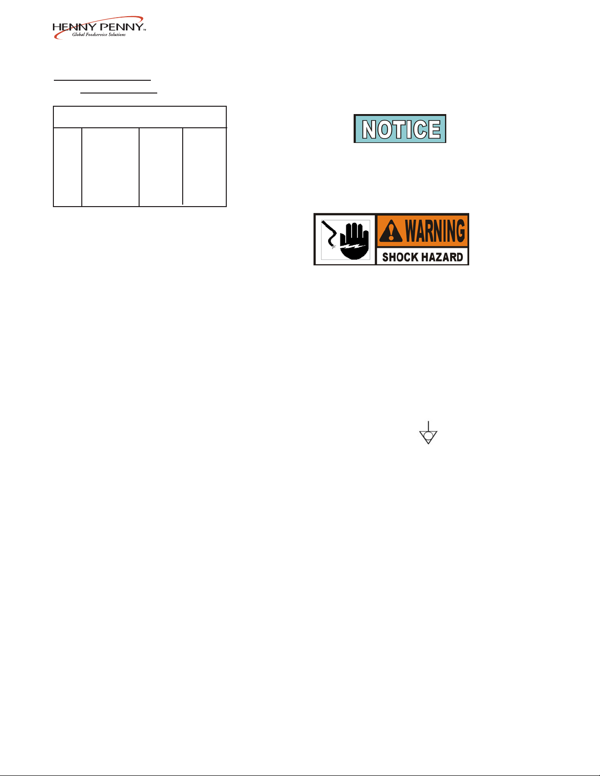
International units are not supplied with cord and plug, and
must be provided upon installation. If two CE units are
placed side-by-side, a grounding wire needs to be placed
between the equipotential bonding lugs, located under the
cutting board brackets, of both units.
This unit must be adequately and safely grounded. Refer to
local electrical codes for correct grounding procedures. If
heated merchandiser is not adequately grounded, electrical
shock could result.
(FOR EQUIPMENT WITH CE MARK ONL Y!)
T o prevent electric shock hazard this appliance must be
bonded to other appliances or touchable metal surfaces in
close proximity to this appliance with an equipotential
bonding conductor . This appliance is equipped with an
equipotential lug for this purpose. The equipotential lug is
marked with the following symbol
A separate disconnect switch with proper capacity fuses or breakers
must be installed at a convenient location between the unit and the
power source.
2-2 1004
Page 9

Model HMR-103,104,105,106,107
2-4. ELECTRICAL DA TA TABLE
COMBI- AMPS COMBI- AMPS
MODEL NATION VOLTS KW 1 PHASE 3 PHASE MODEL NATION VOLTS KW 1 PHASE 3 PHASE
HMR-107 7S 120/208 5.0 24 18 HMR-107 3F/2S/2F* 120/208 6.0 29 19
6.7 32 22 7.8 37 23
120/240 5.0 16 16 120/240 6.0 25 17
7.0 29 20 8.1 34 21
220-240 5.4 22 N/A 220-240 6.4 27 N/A
7.5 31 N/A 8.5 36 N/A
380-415 5.4 N/A 11 380-415 6.4 N/A 11
7.5 N/A 11 8.5 N/A 13
HMR-107 7F 120/208 6.0 29 19 HMR-107 2S/3F/2S 120/208 5.5 27 1 9
7.8 37 23 7.3 35 22
120/240 6.0 25 17 120/240 5.5 23 16
8.1 34 21 7.6 32 20
220-240 6.4 27 N/A 220-240 6.0 25 N/A
8.5 36 N/A 8.0 33 N/A
380-415 6.4 N/A 11 380-415 6.0 N/A 11
8.5 N/A 13 8.0 N/A 1 2
HMR-107 5S/2F* 120/208 5.5 26 18 HMR-107 2F/3S/2F 120/208 5.9 29 19
7.2 35 22 7.7 37 22
120/240 5.5 23 16 120/240 5.9 25 16
7.5 31 20 8.0 33 20
220-240 5.9 24 N/A 220-240 6.4 27 N/A
7.9 33 N/A 8.4 35 N/A
380-415 5.9 N/A 11 380-415 6.4 N/A 11
7.9 N/A 12 8.4 N/A 1 2
HMR-107 5F/2S* 120/208 5.5 27 19 HMR-106 6S 120/208 4.0 19 13
7.3 35 22 5.5 26 16
120/240 5.5 23 16 120/240 4.0 17 12
7.3 30 20 5.7 24 15
220-240 6.0 25 N/A 220-240 4.3 18 N/A
8.0 33 N/A 6.1 25 N/A
380-415 6.0 N/A 11 380-415 4.3 N/A 8
8.0 N/A 12 6.1 N/A 9
HMR-107 4S/3F* 120/208 5.5 27 19 HMR-106 6F 120/208 5.0 24 15
7.3 35 22 6.5 31 20
120/240 5.5 23 16 120/240 5.0 21 13
7.6 32 21 6.8 28 18
220-240 6.0 25 N/A 220-240 5.4 22 N/A
8.0 33 N/A 7.2 30 N/A
380-415 6.0 N/A 11 380-415 5.4 N/A 8
8.0 N/A 12 7.2 N/A 1 2
HMR-107 4F/3S* 120/208 5.5 27 19 HMR-106 4S/2F* 120/208 4.5 21 14
7.3 35 22 6.0 29 17
120/240 5.5 23 16 120/240 4.5 19 12
7.6 32 20 6.2 26 16
220-240 6.0 25 N/A 220-240 4.8 20 N/A
8.0 33 N/A 6.6 27 N/A
380-415 6.0 N/A 11 380-415 4.8 N/A 8
8.0 N/A 12 6.6 N/A 1 0
HMR-107 3S/2F/2S* 120/208 5.5 27 18 HMR-106 4F/2S* 120/208 4.5 22 14
7.2 35 22 6.0 29 17
120/240 5.5 23 16 120/240 4.5 19 12
7.5 31 20 6.3 26 16
220-240 5.9 24 N/A 220-240 4.9 20 N/A
7.9 33 N/A 6.7 28 N/A
380-415 5.9 N/A 11 380-415 4.9 N/A 8
7.9 N/A 12 6.7 N/A 1 0
*Well modules can be arranged in opposite order
703 2-3
Page 10

Model HMR-103,104,105,106,107
2-4. ELECTRICAL DA TA TABLE (Continued)
COMBI- AMPS COMBI- AMPS
MODEL NATION VOLTS KW 1 PHASE 3 PHASE MODEL NATION VOLTS KW 1 PHASE 3 PHASE
HMR-106 3S/2F* 120/208 5.2 25 17 HMR-105 3F/2S* 120/208 4.2 20 14
(Cont.) 6.7 32 20 (Cont.) 5.5 26 17
120/240 5.2 22 15 120/240 4.2 18 12
7.0 29 18 5.7 24 15
220-240 5.5 23 N/A 220-240 4.5 19 N/A
7.3 31 N/A 6.0 25 N/A
380-415 5.5 N/A 11 380-415 4.5 N/A 8
7.3 N/A 11 6.0 N/A 9
HMR-106 2S/2F/2S 120/208 4.5 21 14 HMR-104 4S 120/208 2.6 13 9
6.0 29 17 3.6 17 11
120/240 4.5 19 12 120/240 2.6 11 8
6.2 26 16 3.8 16 10
220-240 4.8 20 N/A 220-240 2.8 12 N/A
6.6 27 N/A 4.0 17 N/A
380-415 4.8 N/A 8 380-415 2.8 N/A 5
6.6 N/A 10 4.0 N/A 6
HMR-106 2F/2S/2F 120/208 4.9 24 14 HMR-104 4F 120/208 3.2 15 9
6.4 31 19 4.2 20 12
120/240 4.9 21 13 120/240 3.2 13 8
6.7 28 18 4.4 18 12
220-240 5.3 22 N/A 220-240 3.4 14 N/A
7.1 30 N/A 4.6 19 N/A
380-415 5.3 N/A 8 380-415 3.4 N/A 5
7.1 N/A 12 4.6 N/A 7
HMR-105 5S 120/208 3.6 18 13 HMR-104 2S/2F* 120/208 3.1 15 9
4.9 24 16 4.1 20 12
120/240 3.6 15 12 120/240 3.1 13 8
5.1 21 15 4.3 18 11
220-240 3.9 16 N/A 220-240 3.3 14 N/A
5.4 23 N/A 4.5 19 N/A
380-415 3.9 N/A 8 380-415 3.3 N/A 5
5.4 N/A 8 4.5 N/A 7
HMR-105 5F 120/208 4.2 20 14 HMR-103 3S 120/208 2.3 11 9
5.5 26 17 3.0 15 11
120/240 4.2 18 12 120/240 2.3 10 8
5.7 24 15 3.2 13 10
220-240 4.5 19 N/A 220-240 2.4 10 N/A
6.0 25 N/A 3.4 14 N/A
380-415 4.5 N/A 8 230 2.4 11 N/A
6.0 N/A 9 380-415 2.4 N/A 5
HMR-105 3S/2F* 120/208 4.1 20 14 3.2 N/A 5
5.4 26 17 HMR-103 3F 120/208 2.8 14 9
120/240 4.3 18 13 3.6 17 11
5.6 23 15 120/240 2.8 12 8
220-240 4.4 18 N/A 3.7 16 10
5.9 25 N/A 220-240 3.0 12 N/A
380-415 4.4 N/A 8 3.9 16 N/A
5.9 N/A 9 230 3.0 13 N/A
380-415 3.0 N/A 5
3.9 N/A 6
*Well modules can be arranged in opposite order
2-4 703
Page 11

2-5. CABINET DIMENSIONS
Model HMR-103,104,105,106,107
803 2-5
Page 12

Model HMR-103,104,105,106,107
2-6. CENTER GLASS These are the instructions for installing the center glass on units
INSTALLATION that are combination, self-serve and standard merchandisers.
1. Notice the location of the bracket on unit, as indicated.
2. Using a 3/8” socket, or nut driver, loosen the 2 acorn nuts
securing the bracket, but do not remove.
3. Slide bracket off from around the 2 acorn nuts.
2-6 1202
Page 13

2-6. CENTER GLASS
INSTALLATION
(Continued)
Model HMR-103,104,105,106,107
4. Place glass in divider track as shown.
5. Slide bracket onto glass and align to its original position
around the 2 acorn nuts.
6. Retighten the 2 acorn nuts.
1202 2-7
Page 14

Model HMR-103,104,105,106,107
2-7. SIDE GLASS Install the side panel glass, on both sides of the unit, as follows:
INSTALLATION
1. Pull out plunger on retainer and turn clockwise to lock open.
2. Slide the glass into the channel on the side rail, making sure the
glass seats into the groove on the upright.
Step 1
3. Align the hole in the glass with the plunger of the retainer.
Step 4
4. Turn the plunger of the retainer clockwise again, to lock and
release the plunger in place.
5. Installation is now complete.
2-8 1202
Page 15

Model HMR-103,104,105,106,107
SECTION 3. OPERATION
3-1. INTRODUCTION This section provides the daily operating procedure for the
heated merchandiser . Read this section thoroughly before
operating the merchandiser.
3-2. ST ART-UP
1. Turn the POWER and HEA T switches to the ON position.
2. Fill water pan assembly (inside the well area) with about 1.5
gallons (5.7 liters) of water. This should provide approximately
8 hours of humidified operation under normal circumstances.
3. Allow approximately 30 minutes preheat time before placing
product into the merchandiser.
4. The lower heat controls are located above the far left well of each
full-serve section, along with the upper heat controls for that well.
The air temperature is shown at all times and can be changed by
using the UP and DOWN buttons. The temperature range is
140º-180º F (60º-82º C).
T o check the actual air temperature, press the button marked
“Press to view Actual T emp.” Also, if the controls are locked, the
controls cannot be changed until the controls are unlocked. See
Special Programming section.
5. The upper heat controls (radiant heat), are located above each
well and can be individually set depending on the types of food
that are being held in each well. The upper heat setting is shown
at all times, and can be changed from settings of 1 to 10, by using
the UP and DOWN buttons.
The upper heat settings read 1, 2, 3, etc. One meaning the heat is
on 10% of the time, 10 meaning the heat is on 100% of the time.
Settings of 9 and 10 have been designed for use when the rear
doors of the unit have been removed. Use of these settings with
the doors in place is not recommended.
6. As a rule, a lower radiant heat setting, such as 3 or 4, holds
dense foods like macaroni and cheese or cherry cobbler. Use
higher upper heat settings for less dense foods, such as fried
chicken.
203 3-1
Page 16

Model HMR-103,104,105,106,107
3-2. ST ART-UP
(Continued)
3-3. OPERA TION WITH
PRODUCT
7. The water (humidity) temperature controls are located above the
water pan of each full serve section. If humidity is desired in the
merchandiser, press the button marked ON to activate the water
pan heater . If “Add H2O” flashes in the display, water needs to
be added to the water pan. If no humidity is desired, press the
OFF button so the water pan heater does not come on.
T o prevent a false “Add H20” code, make sure the water pan is
touching the operator side of the unit, inside the well area.
8. T o use a food temperature probe to monitor food, plug the probe
into a receptacle located above each well inside the unit. Place
the probe into the food, and press the probe button to toggle
between showing the probe temperature and upper heat setting.
1. Rotate food from front to back.
2. Food in half-size pans does not hold as well as food in full size
pans. Rotate pan to back of merchandiser where it is directly
under upper heating elements or move food to a smaller pan that
has been preheated.
3. When freshening foods such as macaroni and cheese with
added water, heat the water in a clean container until it is 10º F to
20º F (6º C to 12º C) above the desired holding temperature of
the food. This will keep food at a safe serving temperature.
Depending on the amount of water, the temperature can drop
10º F to 20º F (6º C to 12º C) in as little as five minutes.
4. When transferring hot foods in the heated merchandiser to clean
pans, preheat the clean pan. Transferring hot foods to room
temperature pans can cause the temperature of the food to drop
20º F (12º C) or more, thus causing food to be at an unsafe
serving temperature.
5. If operating unit with rear doors removed, it is recommended that
third size pans be placed in the center section of the well for
optimal holding. Food temperatures will be maintained for up to
an hour with doors removed and upper heat set to 9 or 10.
Remember to frequently monitor food temperatures.
3-2 1202
Page 17

Model HMR-103,104,105,106,107
3-3. OPERA TION WITH
PRODUCT (Continued)
3-4. SHUT DOWN AND
CLEAN UP
6. T o keep hot foods from drying too fast, keep a clean misting
bottle (such as you find in a garden supply store) with a mixture
of 1/3 vegetable oil and 2/3 water on hand. Set the nozzle for a
fine mist. Shake the vegetable oil and water mixture well. Spray
surface of food immediately , shaking the bottle between each
entree. The frequency with which the foods need to be misted
depends upon the unique characteristics of the food, the water
heat setting in the case and atmospheric conditions. Do not use
this mixture on foods with a pastry crust or crumb toppings
where a dry surface is desirable.
7. If prepackaging foods, place containers directly under
upper heating elements (in back of the case) for maximum
holding time. Upper heat may need to be increased
slightly .
1. Remove all power from the unit by unplugging the unit
from the wall receptacle, or by turning off the wall circuit
breaker.
2. Allow unit to cool before cleaning.
3. Remove rear doors and open front glass.
4. Remove pans, pan supports, and water pan and clean with
soap and water at sink.
5. Clean all surfaces with a soft cloth, soap, and water.
Do not use steel wool, other abrasive cleaners or cleaners/
sanitizers containing chlorine, bromine, iodine or ammonia
chemicals, as these will deteriorate the stainless steel
material and shorten the life of the unit.
Do not spray the unit with water, such as, with a garden
hose. Failure to follow this caution could cause component
failure.
203 3-3
Page 18

Model HMR-103,104,105,106,107
3-4. SHUT DOWN AND
CLEAN UP (Continued)
6. Clean around electrical controls and components with a
damp cloth.
7. Clean doors and glass with a non-streaking liquid glass
cleaner .
Do not use abrasive cleaners or scratches to the glass
may occur.
8. Leave doors open until ready to load and use again.
Cleaning Non-Glare Glass. Use a soft cloth, or sponge, and a
non-abrasive cleaner and water. Dishwashing liquid, or similar
product works well. When cleaning the inside of cases, it is recommended the doors be completely open and covered to prevent
splashing onto the glass, and ruining the glass coating.
Do not use steel wool, scouring pads, cloth with metal
thread, scrapers or other sharp tools, alkaline or acidic
cleaners/sanitizers or cleansers containing flourides, as
these will damage the coated surface of the glass.
3-4 203
Page 19

3-5. LIGHT BULB REPLACEMENT
Model HMR-103,104,105,106,107
T o avoid electrical shock or pr operty damage, move
the POWER switch to OFF and disconnect main
circuit breaker, or unplug cord at wall receptacle.
Light bulbs and glass may be hot. Severe burns could
result.
1. Raise the glass canopy and ensure that the gas shocks
support its weight before proceeding.
Figure 1
Figure 2
Do Not attempt to access the bulb from the operator’s
side of the unit. The installer cannot easily see the bulb
and socket or the adjacent radiant heaters, increasing the
potential shock or burn hazard.
2. Carefully remove the old bulb and discard. Figure 1.
3. Visually inspect socket to ensure there is no debris or damage
that may impede bulb installation. Figure 2.
4. Install the replacement bulb. Tighten using a gentle pressure.
To help prevent a short bulb life:
• Do not over-tighten the bulb. Over-tightening will
damage the contact end of the bulb and compress the
contact tab in the socket.
• Do not install the bulb with the power on. During normal
operation, the socket is exposed to various food related
agents, such as moisture and gr ease. When installing a
new bulb with the power on, the spark that occurs when
the bulb contact touches the socket, places a deposit on
the bottom of the bulb. This deposit results in a higher
amp draw and shorter bulb life.
1104 3-5
Page 20

Model HMR-103,104,105,106,107
3-6. SPECIAL PROGRAMMING
All three controls have the same capability to access the Special
Program Mode. This mode includes; choosing between Fahrenheit
and Celsius, reinitialize the controls, calibrating the food probe, and
output tests.
T o access the Special Program Mode: Press and hold the
temperature button, then turn the power switch on.
1. “ºF” or “C” will show in the display . T o toggle between
Fahrenheit and Celsius, press and release the UP or DOWN
buttons. (ON or OFF buttons on the humidity controls).
2. After entering the Special Program Mode, press and release
the temperature button once and “int” shows in the display .
Press and hold the UP or DOWN button (ON or OFF
buttons on the humidity controls), and the display will count
down “In3”, “In2”, “In1”. This will reinitialize the controls and
set all controls to 0.
3. After entering the Special Program Mode, press and release
the temperature button twice, and “Cal” shows in the display ,
followed by the current probe temperature. The probe can be
calibrated + 10º F , and can be changed by using the UP and
DOWN buttons. (ON or OFF buttons on the humidity controls.)
4. After entering the Special Program Mode, press and release the
temperature button three times, and “P=L”, or “P=U”, shows in
the display . Use the UP and DOWN buttons to toggle between
L (lock) and U (unlock).
5. After entering the Special Program Mode, press and release the
temperature button three times, and “OP” shows in the display .
Use the UP and DOWN buttons to toggle between “888” and a
blank display . “888” turns all heat outputs on, and a blank
display turns them off.
3-6 203
Page 21

Model HMR-103,104,105,106,107
SECTION 4. TROUBLESHOOTING
4-1. TROUBLESHOOTING GUIDE
Problem Cause Correction
Power switch ON but unit
completely inoperative
• Open Circuit
• Plug unit in
• Check breaker or fuse at wall
• Check 15 amp fuses
• Check cord and plug for loose connection
No air heat
Canopy glass fogging
Product not holding temperature
• Unit not preheated
• Water heat setting too high
• Upper heat setting too low
• Doors left open
• Heat settings too low
• Product held too long
• Product not placed correctly in unit
4-2. ERROR CODES AND WARNINGS
DISPLAY
“LO”
CAUSE
• Food probe or actual temperature
is below 50o F (10o C) in calibration
mode only
• Preheat unit with pans in place before
loading product
• Lower water heat setting
• Raise upper heat setting
• Keep doors closed except to load and
unload product
• Adjust heat settings
• Hold product for recommended times
• Place product in unit per Operation with
Product section
CORRECTION
• Allow unit to heat up, or remove food
from unit
“HI”
“E-4”
“E-6”
“E-41”
“E-56”
• Food probe temperature above
500o F (260o C) or lower temperature
275o F (135o C), or above
• Control board temperature above
140o F (60o C)
• Air probe error
• Scrambled PC board memory
• Setpoint storage error
• Turn unit off and call a certified service
technician
• Turn unit off and call a certified service
technician
• Check probe connection at PC board, or
call a certified service technician
• Press UP button to clear “E-41;” if it
reappears, call a certified service technician
• Press UP button to clear “E-56,” then turn
unit OFF and back ON; if “E-56” reap
pears, call a certified service technician
More detailed troubleshooting information is available in the T echnical Manual, available at www .hennypenny .com,
or 1-800-417-8405 or 1-937-456-8405.
203 4-1
Page 22

Model HMR-103,104,105,106,107
G L O S S A R Y
HENNY PENNY HOLDING CABINETS
air temperature probe a round device located inside the cabinet that measures the inside air
temperature and sends that information to the control panel
concentration ring assembly a metal assembly located in the water pan in the bottom of the unit that
helps keep an even humidity level inside the cabinet
clean water pan setpoint a preset temperature at which a sensor warns the operator that the water pan
has excessive lime deposits
control panel the components that control the operating systems of the unit; the panel is
located on the top front surface of the cabinet
deliming agent a cleaner used to remove lime deposits in the water pan
drain valve a device that lets the water drain from the water pan into a shallow pan on
the floor; the valve should be closed while the unit is in use if humidity is
desired
float switch a device that senses low water levels in the water pan
food probe a sensor located outside the cabinet that, when inserted into the product,
communicates the temperature of the product to the control panel
food probe receptacle the connection where the food probe is inserted in order to communicate
with the control panel
humidity sensor a device that measures the percentage of humidity inside the cabinet during
use
humidity setting a preset moisture level at which the cabinet operates; this setting is
programmed at the factory but can be changed in the field
LED an electronic light on the control panel
minimum holding temperature the lowest temperature at which a food product can be safely held for
human consumption
module the removable top part of the cabinet that contains all of the operating
system
out of water trip point a preset temperature at which a sensor warns the operator that the water
pan needs refilled
parameters a preset group of setpoints designed for holding specific food products at
certain temperature and humidity levels
power switch the ON/OFF switch that sends electricity to the unit’s operating systems;
this switch does not disconnect the electrical power from the wall to the unit
pressure sprayer a device that shoots a stream of water under pressure; this device should
NOT be used to clean a holding cabinet
G-1 1202
Page 23

Model HMR-103,104,105,106,107
probe clip a metal holder that attaches to the outside of the control panel to hold the
food probe when not in use; the clip is an optional accessory
product load capacity the highest recommended number of pounds/kilograms of food product that
can be safely held in the cabinet
proof function a program used for allowing bread to rise
relative humidity the humidity level outside the cabinet
setpoint a preset temperature or humidity; the setpoint is a programmable feature
system initialization a programming process that resets factory settings
temperature setting a preset temperature up to which the cabinet will heat; this setting is
programmed at the factory but can be changed in the field
vent activation switch an automatic control that opens and closes the vent on the rear of the
cabinet to maintain the preset humidity level
vented panels openings on the cabinet that allow air access on the sides and rear of the
module
water fill line the line marked on the inside of the water pan that shows the maximum
water level to prevent overflow onto the floor
water heater sensor a part in the water heater that sends a message to the controls when the
water pan is limed up or empty
water jet a device that shoots a stream of water under pressure; this type of device
should NOT be used to clean a holding cabinet
water pan the area in the cabinet that holds water for creating humidity inside the
cabinet
1202 G-2
Page 24

Henny Penny Corporation
P .O.Box 60
Eaton,OH 45320
1-937-456-8400
1-937-456-8402 Fax
Toll free in USA
1-800-417-8417
1-800-417-8434 Fax
*FM05-013-D* Henny Penny Corp., Eaton, Ohio 45320, Revised 4-19-06
www.hennypenny.com
 Loading...