


Planning and installation instructions
Combisteamer (gas)
SizeType no.
(ClassicCombi)
Type no.
(SmartCombi)
615GCC61XXXXGSC61XXXX
620GCC62XXXXGSC62XXXX
115GCC11XXXXGSC11XXXX
120GCC12XXXXGSC12XXXX
215GCC21XXXXGSC21XXXX
220GCC22XXXXGSC22XXXX
*FM07-187B* en-US
Smart Combi
™
Global Foodservice Solutions
Classic Combi
™
306174---0AIAE-- / 14.12.2009 / TAG-MaBr

Planning and installation instructions
Smart Combi
™
Classic Combi
™

5Planning ..............................................................1
5Standards and regulations ............................................1.1
5Ensure conformity with standards ............................................1.1.1
5Water ........................................................................................1.1.2
5Waste water .............................................................................1.1.3
6Electricity ..................................................................................1.1.4
6Gas ..........................................................................................1.1.5
8Room air ..................................................................................1.1.6
8Safety .......................................................................................1.1.7
8Food hygiene ...........................................................................1.1.8
9Relevant laws, institutions and authorities ...............................1.1.9
9Package dimensions and weights ................................1.2
10Weight ..............................................................................1.3
10Scale drawings ...............................................................1.4
10Abbreviations, installation dimensions .....................................1.4.1
11Installation dimensions .............................................................1.4.2
13Unit dimensions .......................................................................1.4.3
17Specifications, water ......................................................1.5
17Specifications, soft water .........................................................1.5.1
17Specifications, hard water ........................................................1.5.2
17Specifications, waste water ......................................................1.5.3
18Specifications, gas .........................................................1.6
18Specification Natural Gas E/H - 20/20 mbar ............................1.6.1
18Specification Natural Gas LL/L - 25/20 mbar ...........................1.6.2
18Specification, liquid gas B/P - 30/50 mbar ...............................1.6.3
19Specifications, power supply ........................................1.7
19Supply line, gas ..............................................................1.8
19Heat loss .........................................................................1.9
20Ambient atmosphere and noise level ...........................1.10
21Transport .............................................................2
21Transporting the unit ......................................................2.1
22Installation ..........................................................3
22Installation information ..................................................3.1
23Mounting the suspension frame in the base frame .....3.2
25Installing tabletop units .................................................3.3
25Installing floor standing units .......................................3.4
3Planning and installation instructions
Global Foodservice Solutions
Contents
Smart Combi
™
Classic Combi
™

25Aligning the rack trolley ...................................................3.5
26Aligning the rack trolley with slide in system EasyIn ....3.6
28Electricity ..............................................................4
28Power cable requirements ...............................................4.1
28Opening and closing the switch cover ...........................4.2
29Description of the terminal strip ......................................4.3
29Connecting the power supply ..........................................4.4
30RS485/RS422 interface .....................................................4.5
31Water ......................................................................5
31Water supply ......................................................................5.1
33Information about the soft water supply ......................................5.1.1
33Information about the hard water supply ....................................5.1.2
34Fitting the T-piece (accessory) ....................................................5.1.3
35Waste water connection ...................................................5.2
35Waste water connection for units with WaveClean .....................5.2.1
36Waste water connection for units without WaveClean ................5.2.2
38Gas .........................................................................6
38Gas supply .........................................................................6.1
40Converting to a different type of gas ..............................6.2
41Hose connection ...............................................................6.3
42Testing for leaks ................................................................6.4
42Checking the connection pressure .................................6.5
43Checking CO2/CO values (ClassicCombi) ......................6.6
44Start CO2 calibration ..................................................................6.6.1
45Measure CO2 values ..................................................................6.6.2
47Display burner status and cooking chamber temperature ..........6.6.3
48Checking CO2/CO values (SmartCombi) ........................6.7
48Starting CO2 calibration .............................................................6.7.1
49Measuring CO2 values ...............................................................6.7.2
51Setting the CO2 content manually ...................................6.8
52Exhaust gas routing .............................................7
54Air outlet connection ............................................8
54Installation under an extraction hood .............................8.1
54Connection to an air outlet duct ......................................8.2
Global Foodservice Solutions
Planning and installation instructions4
Smart Combi
™
Classic Combi
™
Contents

1 Planning
1.1 Standards and regulations
1.1.1 Ensure conformity with standards
→
Ensure that your plans conform to the standards and regulations
applying at the installation location.
NOTICE
The following overviews assist with orientation. They make no claim
to be complete.
1.1.2 Water
DescriptionRelates toStandard
Drinking water protection, preservation of the drinking water
quality
Drinking water supplyDIN 1988-4
Table 1: Standards/regulations relevant to water
1.1.3 Waste water
DescriptionRelates toStandard
Additional specifications to
DIN EN 752 and
DIN EN 12056: Drainage systems on private ground
Waste water qualityDIN 1986-100
Table 2: Standards/regulations relevant to waste water
5Planning and installation instructions
Global Foodservice Solutions
Planning
Smart Combi
™
Classic Combi
™
1.1.4 Electricity
DescriptionRelates toStandard
Provisions for the erection of
high-voltage current systems
with nominal voltages up to
1000 V
Requirements for electronic
components
DIN VDE
0100 ff.
Erection of low-voltage systems
part 5-54: Selection and erection
of electrical equipment – Earthing arrangements, protective
conductors and protective potential equalisation conductors
Potential equalisationDIN VDE
0100-540
Erection of low-voltage systems
part 4-43: Protection for safety
– Protection against overcurrent
Potential equalisation of the
location
DIN VDE
0100-430
Table 3: Standards/regulations relevant to electricity
1.1.5 Gas
DVGW regulations
DescriptionRelates toStandard
Technical regulations for gas
installations (DVGW-TRGI)
Gas supplyG 600
Technical regulations for liquid
gas (TRF)
Gas supply
Installation of the unit
TRF
Gas qualityGas quality
Conditions for supply
G 260/I
Gas quality – Supplementary
rules for 2nd family gases
G 260/II
Installation of gas appliances in
commercial kitchens
Gas supply
Installation of the unit
G 634
Mechanical extraction of flue
gas for gas-fired appliances
without fans
Exhaust gas routingG 660
Table 4: DVWG regulatory standards/provisions relevant for gas
Global Foodservice Solutions
Planning and installation instructions6
Smart Combi
™
Classic Combi
™
Planning

DIN standards/provisions
DescriptionRelates toStandard
Gas-fired catering appliances
– Part 1: General safety requirements
Basic requirementsDIN EN 203-1
Test gases – test pressures –
appliance categories
Types of gasDIN EN 437
Hose assemblies and connection valves for gas; safety hose
assemblies, safety valves with
quick connecting devices
Flexible connectionsDIN 3383,
Par t 1
Hose assemblies and connection valves for gas ; hose assemblies for rigid connection
Flexible connectionsDIN 3383,
Par t 2
Hose assemblies of stainless
steel for gas (draft)
Flexible connectionsDIN 3384
Table 5: DIN standards/provisions relevant for gas
BG Construction standards/provisions
DescriptionRelates toStandard
Regulations for the prevention
of accidents with the use of liquid gas
Scope of the provision: 1. Use
of liquid gas for burning purposes 2. Liquid gas systems
for burning purposes, insofar
as supplied by pressurised
gas containers 3. Liquid gas
systems with gas consuming
appliances for burning purposes, insofar as supplied by
pressurised gas containers.
Gas supply
Appliance installation (formerly
ZH 1/455)
BGV D 34
(formerly VBG
21)
Table 6: BG construction standards/provisions relevant for gas
7Planning and installation instructions
Global Foodservice Solutions
Planning
Smart Combi
™
Classic Combi
™

1.1.6 Room air
DescriptionRelates toStandard
Ventilation equipment for kitchen, basis for planning the
ventilation of commercial kitchens as well as for calculating
the size and construction of
ventilation systems. It applies
in connection with the complete
reference work of DIN 1946.
Priority circuit room ventilation
system
VDI 2052
General conditions for working
environments in kitchens with
regard to the planning of kitchen ventilation systems.
Emissions and comfortASR 5
Table 7: Standards/regulations relevant to room air
1.1.7 Safety
DescriptionRelates toStandard
Safety regulations for kitchens,
kitchen safety equipment (fire
extinguishers...)
Hazards in kitchens (formerly
ZH 1/37)
BGR 111
Table 8: Standards/regulations relevant to safety
1.1.8 Food hygiene
DescriptionRelates toStandard
Regulation about food hygieneDocumentation of heating temperatures according to HACCP
principles
Regulation
(EG) Nr.
852/2004
Table 9: Standards/regulations relevant to hygiene
Global Foodservice Solutions
Planning and installation instructions8
Smart Combi
™
Classic Combi
™
Planning

1.1.9 Relevant laws, institutions and authorities
Name of the institute/authority
Relates toStandard
Regional gas or energy supplier (GVU) or network operator
Gas supply
Installation of the unit
TAB (Technical
Connection
Conditions)
GAS (Low
Pressure Gas
Supply
(NDAV))
Building inspection authoritiesGas supply
Installation of the unit
BauO (Building
Regulations);
LBO (Regional
Building Regulations)
Trading standards officeInstallation of the unitGewO (Trade,
Commerce and
Industry regulations)
Responsible district chim-
ney/heating inspector
Gas supply
Installation of the unit, emissions
BauO (Building
Regulations);
FeuVo (Ordinance on Firing
Installations),
BISchV (Federal Emission
Control Ordinance)
Water/waste water association
or authority
Installation of the unit
Water/waste water connections
AbwV (Waste
Water Ordinance)
ATV information sheets
(Association of
Waste Water
Technicians)
Technical connection condi-
tions for connecting to the low
voltage mains network, require-
ments applying to the installa-
tion location
Mains network operators,
power suppliers
Installation of the unit
Mains connection
TAB (Technical
Connection
Conditions)
POWER (NAV
- Ordinance on
Low-Voltage
Connections)
Table 10: Relevant laws, institutions, authorities
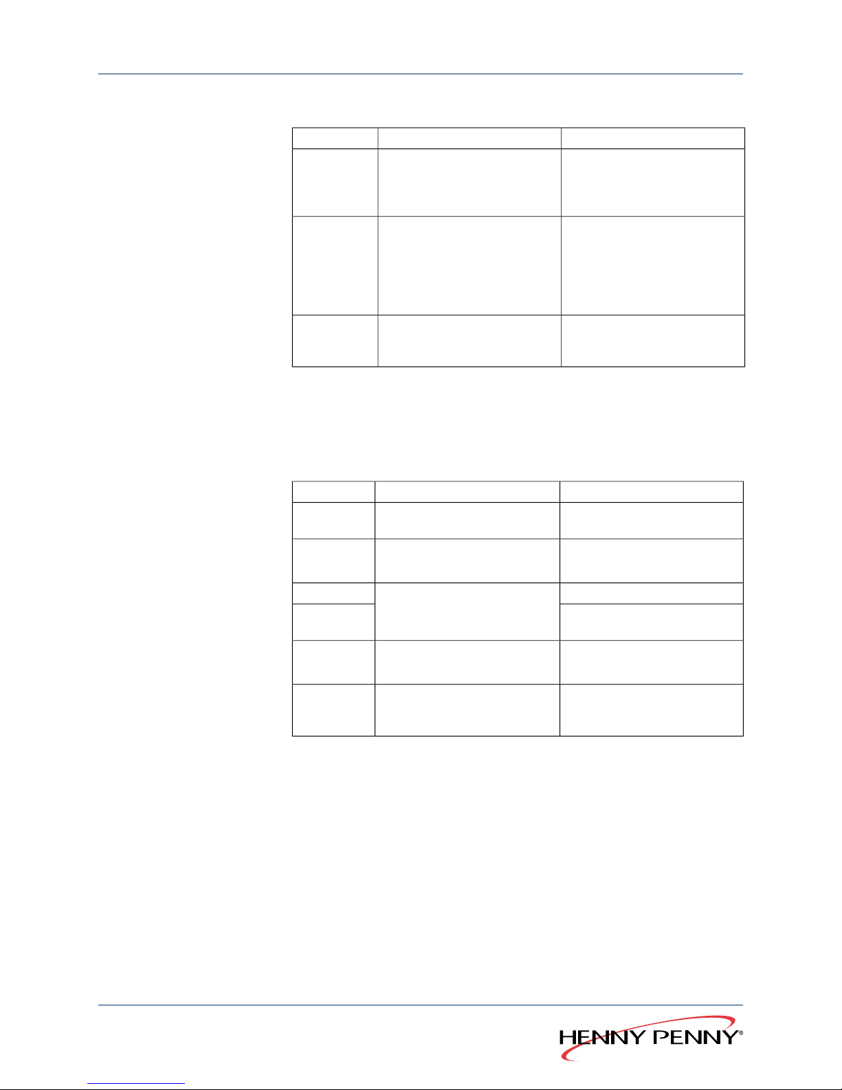
1.2 Package dimensions and weights
NOTICE
These specifications may be modified for technical reasons.
9Planning and installation instructions
Global Foodservice Solutions
Planning
Smart Combi
™
Classic Combi
™

Gross weight (lb.)Package dimensions (in.)
Depth x width x height
Size
374.842.5 x 37.8 x 40.2615/620
429.942.5 x 37.8 x 50.4115/120
826.745.7 x 37.8 x 86.6215/220
Table 11: Package dimensions and weights
1.3 Weight
NOTICE
These specifications may be modified for technical reasons.
Weight (lb.)Size
302.0615
313.1620
368.2115
412.3120
782.6215
782.6220
Table 12: Weight
1.4 Scale drawings
1.4.1 Abbreviations, installation dimensions
MeaningAbbreviation
WidthB
Width, distance from wall to the left of the unitBL
Width, distance from wall to the right of the unitBR
HeightH
Height, distance from the ceilingHD
Height, unit feetHF
Height, overallHG
Height, tableHT
DepthT
Depth, distance to wall behind the unitTH
Table 13: Abbreviations, installation dimensions
Global Foodservice Solutions
Planning and installation instructions10
Smart Combi
™
Classic Combi
™
Planning

1.4.2 Installation dimensions
B
BR
TH
H
HG
HF
HT
BL
T
Figure 1: Installation dimensions of combisteamers 615/620 and 115/120
B
BR
TH
H
HG
HF
BL T
Figure 2: Installation dimensions, combisteamer 215/220
THTHTHGHFHBRBLBSize
5079985016401006905050997615/620
5079958016401009605050997115/120
50813 1960238172250501075215/220
Table 14: Installation dimensions in mm
11Planning and installation instructions
Global Foodservice Solutions
Planning
Smart Combi
™
Classic Combi
™

NOTICE
A clearance of at least 50 mm from walls must be maintained to the
right and the left of the unit as well as behind it.
A minimum distance of 500 mm to the left is recommended for servicing.
When using rack trolleys, the distance to the left of the unit should be
at least 800 mm to allow the trolley to be positioned at the side.
Global Foodservice Solutions
Planning and installation instructions12
Smart Combi
™
Classic Combi
™
Planning

1.4.3 Unit dimensions
MeaningAbbreviation
Drain (waste water)A
Flue outletAG
Air outletAL
Electrical connectionEA
Soft water, coldEW
Gas supplyCM
InterfaceKE
Cold water, hardKW
Performance optimisation systemLOA
Potential equalisation connectionPA
Centre of gravityS
Control lead, externalSTL
13Planning and installation instructions
Global Foodservice Solutions
Planning
Smart Combi
™
Classic Combi
™

72
PA
EW
KW
760
223
163
138
93
61
38
140
97
73
52
EA
GA
STL
50
50
100
278
73 897
A
53
100
+20
0
790
849
AL Ø53
50
165
1020
52
799
100 535
76
Figure 3: Combisteamer 615/620, unit dimensions in mm
Global Foodservice Solutions
Planning and installation instructions14
Smart Combi
™
Classic Combi
™
Planning

KE
140
71
100
97
73
52
LOA
EA
STL
50
50
73
278
897
+20
0
100
PA
EW
KW
760
223
163
138
93
61
38
54
1060
113 8
1020
AL Ø53
52
799
100
535
76
50
Figure 4: Combisteamer 115/120, unit dimensions in mm
15Planning and installation instructions
Global Foodservice Solutions
Planning
Smart Combi
™
Classic Combi
™

KE
67
EA
EW
KW
759
303
243
139
133
75
52
141
118
103
90
52
PA
GA
STL
50
50
39
233
996
187
238±20
1960
2009
AL Ø73
50
170
1075
50
813
93 609
76
100
Figure 5: Combisteamer 215/220, unit dimensions in mm
Global Foodservice Solutions
Planning and installation instructions16
Smart Combi
™
Classic Combi
™
Planning

1.5 Specifications, water
1.5.1 Specifications, soft water
ValueParameters
Drinking water, coldType
2–6 bar/200–600 kPaSupply pressure
< 1.5 mmol/l, < 5 °dH (soft water)Hardness
¾" outside threadThread
DN 15 hose with ¾" union nutConnection
Table 15: Specifications, soft water
1.5.2 Specifications, hard water
ValueParameters
Drinking water, coldType
Up to 50 °C (122 °F)Temperature
2–6 bar/200–600 kPaSupply pressure
0–4 mmol/l, 0–25 °dHHardness
¾" outside threadThread
DN 15 hose with ¾" union nutConnection
Table 16: Specifications, hard water
1.5.3 Specifications, waste water
ValueParameters
Up to 80 °C (176 °F)
For adjusting the waster water temperature, see chapter “Standard settings”
in the operating manual.
Temperature
DN 50 direct connectionConnection
Table 17: Specifications, waste water
17Planning and installation instructions
Global Foodservice Solutions
Planning
Smart Combi
™
Classic Combi
™

1.6 Specifications, gas
1.6.1 Specification Natural Gas E/H - 20/20 mbar
ValueParameters
A3, B23Model EN 203-1:2005
15–25 mbarConnection pressure EN 437:2003-09
45.67 MJ/m
3
Wobbe index W
i
34.02 MJ/m
3
Heating value H
i
50.72 MJ/m
3
Wobbe index W
s
37.78 MJ/m
3
Calorific value H
s
¾" outside threadThread
Table 18: Specification Natural Gas E/H - 20/20 mbar
1.6.2 Specification Natural Gas LL/L - 25/20 mbar
ValueParameters
A3, B23Model EN 203-1:2005
15–30 mbarConnection pressure EN 437:2003-09
37.38 MJ/m
3
Wobbe index W
i
29.25 MJ/m
3
Heating value H
i
41.52 MJ/m
3
Wobbe index W
s
32.49 MJ/m
3
Calorific value H
s
¾" outside threadThread
Table 19: Specification Natural Gas LL/L - 25/20 mbar
1.6.3 Specification, liquid gas B/P - 30/50 mbar
ValueParameters
A3, B23Model EN 203-1:2005
15–57.5 mbarConnection pressure EN 437:2003-09
80.58 / 70.69 MJ/m
3
Wobbe index W
i
116.09 / 88.00 MJ/m
3
Heating value Hi per m
3
45.65 / 46.34 MJ/kgHeating value Hi per kg
87.33 / 76.84 MJ/m
3
Wobbe index W
s
Global Foodservice Solutions
Planning and installation instructions18
Smart Combi
™
Classic Combi
™
Planning

ValueParameters
125.81 / 95.65 MJ/m
3
Calorific value Hs pro m
3
49.47 / 50.37 MJ/kgCalorific value Hs pro kg
¾" outside threadThread
Table 20: Specification, liquid gas B/P - 30/50 mbar
1.7 Specifications, power supply
SizeParameters
220215120115620615
1 N PE/AC 50 HzMains type
230 VVoltage
1.5 kW0.8 kWConnected load
IP X5Protection type
1 x 16 AFuses
Table 21: Specifications, power supply
1.8 Supply line, gas
Connected load (kW)Size
11615
17620
18115
26120
36215
52220
Table 22: Supply line, gas
1.9 Heat loss
Latent (kW)Sensible (kW)Size
2,201,70615
3,402,60620
3,602,70115
5,203,90120
7,205,40215
10,407,80220
Table 23: Heat loss
19Planning and installation instructions
Global Foodservice Solutions
Planning
Smart Combi
™
Classic Combi
™

1.10 Ambient atmosphere and noise level
ValueParameters
5 °C (41 °F)–40 °C (104 °F),
95% relative humidity, non condensing
Ambient atmosphere
< 70 dB (A)Noise level
Table 24: Ambient atmosphere and noise level
Global Foodservice Solutions
Planning and installation instructions20
Smart Combi
™
Classic Combi
™
Planning

2 Transport
2.1 Transporting the unit
L
H
B
NOTICE
The units are delivered on pallets in cardboard casing. Packed in this
way, the units cannot be stacked and are not protected from moisture.
Packed units can be transported lengthways or crossways with a
pallet truck.
Unpacked floor standing units can be lifted at the guiding rails.
CAUTION
Damage due to incorrect transportation
→
Do not position a fork lift in the cooking chamber.
→
When using a fork lift truck, make sure that the siphon, which
protrudes downwards, and the waste water pipe are not damaged.
→
Do not lift tabletop units by the chamber door or the operation
panel.
→
Always transport units upright, do not tip or stack.
1. Consider the package dimensions and weight when choosing a
method of transport (see Chapter “Package dimensions and
weights”, Page 9).
2. Always transport units upright, do not tip or stack.
3. Secure palettes against slipping and tipping over.
21Planning and installation instructions
Global Foodservice Solutions
Transport
Smart Combi
™
Classic Combi
™

3 Installation
3.1 Installation information
Before installing
NOTICE
Examine the unit for transportation damage. Do not install or use
damaged units.
Remove the protective film from the external panels before using for
the first time.
Remove foam transport protection from the chamber.
Fire prevention regulations
NOTICE
Observe the local fire prevention regulations when installing near to
materials that are heat sensitive or endangered by fire.
Covers on top of the unit must be fire-proof.
Units may only be installed on or against fire-proof surfaces and in
compliance with fire prevention regulations.
Installation in buildings The floor or table must be able to bear the weight of the unit (see Chapter
“Weight”, Page 10).
If there is a drainage grating in front of the unit, the customer should fit a
ramp to enable the rack trolley or loading trolley to be pushed across.
Installing below ground
level
NOTICE
When installing the unit in rooms below ground level (cellars), the current
local provisions for liquid gas, in particular, are to be observed when
connecting and operating the gas combisteamer.
Minimum clearances A minimum clearance of 50 mm (2") must be maintained from walls to
the sides and behind the unit and at least 0.5 m (1.6 ft.) above the unit
for servicing.
Global Foodservice Solutions
Planning and installation instructions22
Smart Combi
™
Classic Combi
™
Installation

When using rack trolleys, there should be a minimum distance of at
least 0.8 m (2.6 ft.) to allow the trolley to be positioned at the side.
Heat sources, such as ovens (2) must be at least 0.5 m (1.6 ft.) away
so that the cooling air drawn in under the base is not warmed.
WARNING
Possible danger
→
Non-compliance may pose a threat of death or serious injury.
Fryers or deep fat fryers must be positioned outside of the splash zone
(3) of the hand shower. Splashes of water in hot grease can lead to
serious burns.
Air intake and blow out
vents
NOTICE
The unit's air intake and blow out vents must not be blocked or
covered!
Avoid sources of heat and steam at the sides or behind the unit.
If this is not possible, use shields to prevent warm or damp air from
being drawn into the unit.
The air intake and blow out vents are situated underneath the unit.
Affix “Risk of scalding”
warning
A warning notice must be mounted on the door of the cooking chamber
if units are installed in such a way that the upper slide-in rails exceed
a height of 1.60 m (5.3 ft.).
The warning “Risk of scalding” warns about the danger of scalding that
exists when the contents of a container being pulled out cannot be
seen.
3.2 Mounting the suspension frame in the
base frame
Depending on the version, the base frame can be equipped with
suspension frames for taking GN containers, trays and racks.
Bolts on the vertical supports indicate that it is possible to fit suspension
frames.
NOTICE
The following illustrations show 4 suspension frames (2 sets).
23Planning and installation instructions
Global Foodservice Solutions
Installation
Smart Combi
™
Classic Combi
™

1. Mount the inner suspension frames.
2. Push the rear stop profiles (right/left) onto the bolts.
3. Mount the outer suspension frames (right/left).
Global Foodservice Solutions
Planning and installation instructions24
Smart Combi
™
Classic Combi
™
Installation

3.3 Installing tabletop units
NOTICE
A warning notice must be mounted on the door of the cooking chamber
if tabletop units are installed in such a way that the upper slide-in rails
exceed a height of 1.60 m (5.3 ft.).
The label warns about the danger of scalding that exists when the
contents of a container being pulled out cannot be seen.
1. Observe the instructions for installation (see Chapter “Installation
information”, Page 22).
2. Make sure that the table is able to bear the weight of the unit.
3. Position the unit horizontally level. Correct the alignment using the
feet, if necessary.
4. Remove moisture and grease from the area for affixing the warning
notice.
5. Attach the warning notice on the door of the cooking chamber.
3.4 Installing floor standing units
1. Observe the instructions for installation (see Chapter “Installation
information”, Page 22).
2. Make sure that the floor is able to bear the weight of the unit.
3. Position the unit horizontally level. Correct the alignment using the
feet, if necessary.
3.5 Aligning the rack trolley
NOTICE
Floor standing units may only be operated with a rack trolley. The
rack trolley forms part of the seal of the cooking chamber.
If the rack trolley is not correctly aligned the cooking chamber will not
be sealed properly. Water can escape during cooking and the food
will not be cooked evenly.
1. Check whether the floor underneath and in front of the unit is level.
2. Level out small differences with the unit's feet.
25Planning and installation instructions
Global Foodservice Solutions
Installation
Smart Combi
™
Classic Combi
™

3. Place spacer plates in the frame of the rack trolley if the condition of
the floor is unsuitable.
4. Check the alignment of the rack trolley and correct it if necessary.
The rails in the unit are horizontal.
There is no gap between the sealing plate on the rack trolley and the door
seal.
3.6 Aligning the rack trolley with slide in
system “EasyIn”
Floor standing units in sizes 215 and 220 are equipped with the “EasyIn”
slide-in system. With the “EasyIn” slide-in system, the rack trolley is lifted
and slides into the unit on rails.
Irregularities of up to 10 mm (0.4") in the floor can be evened out in this
way.
WARNING
Risk of damage or personal injury
There is at least 1100 lbs (500 kg) = 4 load points of 275 lbs (125 kg)
on the adjustable legs.
→
To prevent damage or personal injury, ensure that the floor is strong
enough.
CAUTION
Damage to equipment due to incorrect height adjustment
If the minimum distance (y) is not observed, rails and rollers can be
damaged.
→
Set up the unit horizontally, adjust alignment using the feet, if
necessary.
→
Observe a minimum clearance of 1 mm in the take-up area.
NOTICE
Floor standing units may only be operated with a rack trolley. The rack
trolley forms part of the seal of the cooking chamber.
If the rack trolley is not correctly aligned the cooking chamber will not
be sealed properly. Water can escape during cooking and the food will
not be cooked evenly.
Global Foodservice Solutions
Planning and installation instructions26
Smart Combi
™
Classic Combi
™
Installation

1. Push the rack trolley into the take-up area.
x
y
2. In the take-up area (x), there must be a clearance (y) of at least
1 mm between the rollers and the rails.
The clearance (y) should not exceed 5 m.
Correct the clearance (y) using the feet, if necessary.
3. Check whether the rails are horizontal.
Correct the alignment using the feet, if necessary.
k
4. Push the rack trolley further onto the lifting bevel (k) into the unit.
The rack trolley will be lifted up.
5. Push the trolley into the unit as far as it will go.
The wheels should no longer touch the floor when the unit is fully
pushed in. The rack trolley is only supported by the carrying rollers.
27Planning and installation instructions
Global Foodservice Solutions
Installation
Smart Combi
™
Classic Combi
™

4 Electricity
4.1 Power cable requirements
LK
The unit is delivered as standard without a connection cable. A H07RN-F
cable complying with EN standards or, respectively, with the locally
applying provisions, must be used for connecting the unit. The table shows
the length of cable required inside the unit.
Cable length (LK) (cm)Size
80615/620
80115/120
100215/220
4.2 Opening and closing the switch cover
DANGER
Danger due to high voltage
There are voltage-carrying components behind the switch cover.
→
Disconnect the unit from the power supply before opening the switch
cover.
→
Do not operate the unit when the switch cover is open.
1. Pull the hand shower out approx 20 cm.
2. Screw in the hexagonal socket screw (size 5) on the underside of
the switch cover as far as it will go.
3. Press the switch cover lightly and lift approx 20 mm upwards.
4. Raise the switch cover approx 20 mm and lower it again
5. Open the switch cover fully.
6. Check that the seal around the switch cover fits properly and that it
is not damaged.
7. Replace a damaged seal, if necessary.
8. Close the switch cover carefully.
When doing so, ensure that cables are not trapped and that the
cooling fan cannot be obstructed by any cables.
9. Press the switch cover lightly and lift approx 20 mm upwards.
10. Close the switch cover fully and lower it again pressing lightly.
11. Check that the seal around the switch cover fits properly.
Global Foodservice Solutions
Planning and installation instructions28
Smart Combi
™
Classic Combi
™
Electricity

12. If necessary, open the switch cover and correct the position of the
seal.
13. Screw out the hexagonal socket screw (size 5) on the underside
of the switch cover.
4.3 Description of the terminal strip
A1/X5.11
A1/X5.12
K1/A2
X3
PE PE PE13 N 11 12 12 3 4
A_TXD+
B_TXD-
B_RXD-
A_RXD+
YE
GN
BN
WH
H13/A1
R = 150 Ω
Figure 6: Terminal strip
DescriptionTerminalTerminal
strip
External buzzer
External signalling device activated via an auxiliary
relay.
13X3
N
PE
Extraction hood, potential-free11
12
PE
RS485/RS422 interface1
2
3
4
PE
4.4 Connecting the power supply
The unit may only be connected and serviced by an authorised electrical
technician, according to the provisions of the German Association of
29Planning and installation instructions
Global Foodservice Solutions
Electricity
Smart Combi
™
Classic Combi
™

Electrical Technicians, the power supply company and the information
on the nameplate.
Have damaged power cables replaced by customer service to avoid risks
of damage or injury.
The connection can be made either with a plug or by connecting directly.
Isolator with direct connections
The power supply must be fitted with an all pole isolator (e.g. automatic
cutout) with a minimum contact opening of 3 mm, so that the unit can be
removed from the mains at any time.
Plug connection
The plug socket must be adequately protected.
Potential equalisation
The unit can be included in a potential equalisation system (grounding).
The connection terminal is underneath the information plate.
1. Prepare the connection cable (see Chapter “Power cable
requirements”, Page 28).
2. Remove the left side panel.
3. Pass the connection cable through the strain relief screws into the
unit.
4. Connect the connection cable with the connecting terminals according
to the connection diagram.
5. Sizes 115 and 120: Secure the connection cable additionally with
cable clips.
6. Secure the left side panel.
4.5 RS485/RS422 interface
SmartCombi units are equipped as standard with a four-pin RS485
interface; this is optional with ClassicCombi. The interface can be reduced
to a two-pin RS422 interface.
1. Bridge the terminals to reduce the interface to a two-pole RS422
interface.
- X3/1 to X3/3
- X3/2 to X3/4
2. Use twisted wires (e. g. LiYY (TP) 2x2x0.5) for the connection.
3.
Close the last unit with a 150 Ω terminating bus resistor.
Global Foodservice Solutions
Planning and installation instructions30
Smart Combi
™
Classic Combi
™
Electricity

5 Water
5.1 Water supply
The unit is equipped with two water connections:
●
a soft water connection for producing steam
●
a hard water connection for cooling waste water, for operating the
hand shower and for the automatic cleaning system “WaveClean”
For units that are equipped with the “WaveClean” automatic cleaning
system, use of “WaveClean” is not possible without a hard water
connection.
NOTICE
Both water supplies must always be connected.
Hard and soft water connections can be made via a hose with a
T-piece (accessory) in the event that only soft water is available on
site (see Chapter “Fitting the T-piece (accessory)”, Page 34).
NOTICE
When using the stacking kit (accessory), the upper and lower units
must be connected independently so that the other unit can still be
used in the event that one unit fails.
1. Observe information about the hard water supply (see Chapter
“Information about the hard water supply”, Page 33).
2. Observe information about the soft water supply (see Chapter
“Information about the soft water supply”, Page 33).
3. Ensure that customer-supplied water hoses fulfil the requirements
for the hard and soft water supplies (see Chapter “Specifications,
soft water”, Page 17 and Chapter “Specifications, hard water”,
Page 17).
4. Make sure that the provisions for the supply of drinking water are
complied with (see Chapter “Water”, Page 5).
5. Ensure that the water stop-cock is fitted with a backflow preventer.
6. Use ½" hoses with an R ¾" thread permitted for connecting drinking
water for the connection.
NOTICE
Use DVGW-tested hoses, or hoses conforming to the local regulations,
according to IEC 61770.
31Planning and installation instructions
Global Foodservice Solutions
Water
Smart Combi
™
Classic Combi
™

7. When preparing the hoses, calculate the length to allow 0.8 m to be
pulled out from the unit after connection, for later servicing.
8. Rinse out customer-supplied hoses for the hard and soft water
connections.
9. Make sure that the filters fitted as standard to the unit's water inlets
are present.
CAUTION
Damages caused by incorrect water supply
→
Do not confuse the hard water and the soft water connections.
NOTICE
The connections for hard and soft water are located on the floor of the
unit on the left.
2
1
Figure 7: Water connections, tabletop units
1
2
Figure 8: Water connections, floor standing units
Global Foodservice Solutions
Planning and installation instructions32
Smart Combi
™
Classic Combi
™
Water

10. Connect the hose for the hard water supply to the hard water
connection (1).
11. Connect the hose for the soft water supply to the soft water
connection (2).
5.1.1 Information about the soft water supply
Cl/Fe content If the Cl content is greater than 150 mg/l, Fe content greater
than 0.1 mg/l or Cl
2
content greater than 0.1 mg/l, corrosion can occur
in the cooking chamber.The Cl content can be reduced with an
activated charcoal filter.
Supply pressure If the supply pressure is not within the given limits (see Chapter
“Specifications, soft water”, Page 17), the cooking art “Steaming” will
fail to produce any steam.
Contamination of the water If the water is heavily contaminated, a sedimentation filter (grit size
0.08 mm) must be installed upstream.
Water hardness Scale deposits may form if the total water hardness or carbonate
hardness exceeds 5 °dH (0.89 mmol/l). For values smaller than this,
the scale formation is correspondingly less. A total water hardness or
carbonate hardness of 1 °dH is ideal. Certain water components (Na
+
ions and silicates) can cause the windows to become cloudy.This effect
depends on the quality of the water and how the unit is used.
Decarbonisation or full desalination systems can prevent the formation
of scale deposits.
A water softening system should be installed upstream if the water is
very hard.
Water softening systems based on electromagnetic fields do not provide
protection against scale deposits with combisteamers.
Pipes from galvanized steel or other corrosive material may not be
used downstream from water softening systems.
Systems with phosphate and silicate dosing may not be used. Deposits
may form in the cooking chamber with such systems.
SmartCombi units can show the service intervals of a connected water
softening system on the multi-function display.You will find further
information in the operating instructions.
5.1.2 Information about the hard water supply
Cooling waste steam Cold water that has not been softened can be used for cooling waste
steam.
33Planning and installation instructions
Global Foodservice Solutions
Water
Smart Combi
™
Classic Combi
™

Warm water leads to increased water consumption and should not be
used.
The water temperature must not exceed 50 °C (122 °F).
Automatic cleaning system
“WaveClean”
Units that are equipped with the “WaveClean” automatic cleaning system
must always be connected to a hard water and a soft water supply.
Otherwise, cleaning with “WaveClean” is not possible.
5.1.3 Fitting the T-piece (accessory)
Hard and soft water connections can be made via a hose with a T-piece
(accessory) in the event that only soft water is available on site.
Figure 9: Position of the T-piece
Global Foodservice Solutions
Planning and installation instructions34
Smart Combi
™
Classic Combi
™
Water

1
2
3
Figure 10: Parts of the T-piece
1 Sealing ring
2 Threaded connector
3 Metal ring
1. Check that both sealing rings (1) are lying flat in the threaded
connectors (2).
2. Screw the threaded connectors (2) evenly onto the hard and soft
water connections and tighten securely. Avoid cross-threading.
CAUTION
Damage to the unit caused by water
→
Check that the metal rings are positioned correctly.
3. Check that both metals rings (3) are lying on the respective plastic
sprocket in the threaded connector (2).
If not, open the threaded connector (2) and repeat the process.
5.2 Waste water connection
5.2.1 Waste water connection for units with WaveClean
The unit is equipped with a siphon (odour trap) with an overflow and
can be connected to the waste water system without taking additional
action. Customer-supplied siphons should be avoided.
35Planning and installation instructions
Global Foodservice Solutions
Water
Smart Combi
™
Classic Combi
™

1
2
3
If the waste water outlet is connected to a customer-supplied siphon (1),
counter pressure may cause the siphon in the unit (3) to overflow.
Therefore, the waste water pipe must be fitted with an aerator in this case.
A PA-I 1818 DIN 19560 HT pipe is recommended for the connection to
the waste water system.
The diameter of the waste water pipe must not be reduced.
CAUTION
Damage caused by an incorrect water connection
→
Do not operate the unit without an aerator in the waste water pipe.
1. Make sure that customer-supplied pipes meet the requirements for
the waste water connection (see Chapter “Specifications, waste
water”, Page 17).
2. Observe the provisions for the disposal of waste water (see Chapter
“Waste water”, Page 5).
3. Connect the unit to the waste water system using a heat-proof pipe
(DN 50).
4. With customer-supplied siphons: connect aerator to a waste water
pipe.
5. With customer-supplied siphons: pour 2 quarts (2 l) of drinking water
into the siphon.
This ensures the siphon will work properly.
5.2.2 Waste water connection for units without WaveClean
CAUTION
Risk of damage by waste steam
→
To protect the unit from damage caused by waste steam, the funnel
must not be positioned below the unit.
NOTICE
Units without WaveClean are supplied without a built-in overflow.
Therefore, they may only be connected to the waste water system via
an open drain in a funnel.
Global Foodservice Solutions
Planning and installation instructions36
Smart Combi
™
Classic Combi
™
Water

DN 50
DN 50
5% (3°)
1. Make sure that customer-supplied pipes meet the requirements
for the waste water connection (see Chapter “Specifications, waste
water”, Page 17).
2. Observe the provisions for the disposal of waste water (see Chapter
“Waste water”, Page 5).
3. Connect the unit to the waste water system using a heat-proof pipe
(DN 50) and a funnel.
37Planning and installation instructions
Global Foodservice Solutions
Water
Smart Combi
™
Classic Combi
™

6 Gas
6.1 Gas supply
Requirements The following conditions must be met before the gas pipeline is connected
to the unit:
●
All gas connection parts (also those supplied by the customer) must
be tested according to DIN-DVGW (German Association for Gas and
Water).
●
The central gas supply must not be located within the safety distances
and must be freely accessible.
●
The supply pipeline must have a diameter of at least ¾“.
WARNING
Risk of fire
Unintended moving of the appliance results in damage to gas line and
possible fire.
→
Do not equip this appliance with casters or with stands with casters.
→
Do not equip this appliance with stands with casters.
CAUTION
Material damage due to insuffient aeration
The amount of fresh air needed for proper combustion is dependent
upon the input power (BTU/hr) of the appliance. In rooms in which the
nominal heat loading caused by all gas appliances is less than 170,721
BTU/hr (50 kW), air supply via external joints or openings into the open
air is permissible.
→
Ensure sufficient supply of combustion air.
Global Foodservice Solutions
Planning and installation instructions38
Smart Combi
™
Classic Combi
™
Gas

CAUTION
Damage caused by incorrect gas connection
→
Do not confuse the gas connection with the water connection.
→
Contact customer service in the event that the gas connection is
confused with the water connection.
NOTICE
The unit is intended for a fixed connection by the customer. The gas
connection can be made via a gas socket.
The unit may only be installed by an authorised installation company
contracted by the respective gas supplier.
The regulations of the local gas supply company must be complied
with (see Chapter “Standards and regulations”, Page 5).
1. Check whether the type of gas available corresponds to that given
on the nameplate.
2. Convert the unit to the type of gas available if this differs from that
given on the name plate (see Chapter “Converting to a different
type of gas”, Page 40).
3. Observe the information about the hose connection (see Chapter
“Hose connection”, Page 41).
1
4. Attach the gas hose to the ¾" steel pipe outlet under the floor of
the unit (1).
5. Test for leaks (see Chapter “Testing for leaks”, Page 42).
6. Test the connection pressure (see Chapter “Checking the
connection pressure”, Page 42).
7. Check CO
2
/CO values in the exhaust gas.
39Planning and installation instructions
Global Foodservice Solutions
Gas
Smart Combi
™
Classic Combi
™

6.2 Converting to a different type of gas
NOTICE
When converting to a different type of gas, the burner orifice must be
changed. The orifices, together with an orifice table, are in a plastic bag
located in the connection compartment.
1
1
1
1. Switch the unit off at the mains (switch off circuit breakers or remove
the plug) and shut off the central gas supply.
2. Remove the fixing screws at the bottom of the unit on the left.
3. Remove the side panel.
With floor standing units: remove one screw at the top and one at the
bottom.
With tabletop units: remove two screws at the bottom and two in the
middle.
4. Remove the fixing screws for the gas valve.
5. Remove the gas valve.
1
2
6. Remove gas orifice with seal (1).
7. Select orifice according to the orifice table and refit it using an
undamaged seal (2).
8. Mount the gas valve and screw it tightly.
9. Reopen the central gas supply.
10. Start the unit.
11. Switch the power supply back on.
After the type of gas has been converted, you can proceed with the leak
test, the connection pressure test and the calibration of the CO
2
/CO
values.
Global Foodservice Solutions
Planning and installation instructions40
Smart Combi
™
Classic Combi
™
Gas

6.3 Hose connection
Gas hose and fitting
connections in the same
plane
Left: correct; Right: incorrect
If the connection points are laterally offset, this will cause additional
torsional stress and heavy strain on the hose.This leads to premature
failure.
Connection with a metal
hose
Left: correct; Right: incorrect
Make sure that the hose has only one bend. A strained or twisted metal
hose can lead to early failure of the connection.
Minimum bending
diameter
Left: correct; Right: incorrect
41Planning and installation instructions
Global Foodservice Solutions
Gas
Smart Combi
™
Classic Combi
™

If the separation between the two connection points is less than the
minimum bending diameter, it results in the hose ends bending in opposite
directions. This leads to fatigue fractures.
6.4 Testing for leaks
NOTICE
Use only DVGW-approved foam forming agents or those that have been
tested according to locally applying regulations!
Do not spray leak spray onto the wires of the ignition electronics.
Electronic gas detectors also react to exhaust gas (CO).Therefore, the
null calibration of an electronic gas detector should be done outdoors.
→
Test all connections inside and outside the unit for leaks according
to the “technical provisions for the gas installation” , using a gas
detector or leak spray.
6.5 Checking the connection pressure
Requirements All connections inside and outside the unit are free of leaks (see Chapter
“Testing for leaks”, Page 42).
NOTICE
The manometer should be accurate to at least 0.1 mbar.
1. Switch the unit off at the mains (switch off circuit breakers or remove
the plug) and shut off the central gas supply.
2. Unscrew the side panel.
With tabletop units: remove one screw at the top and one at the
bottom.
With floor standing units, remove two screws at the bottom and two
in the middle.
Global Foodservice Solutions
Planning and installation instructions42
Smart Combi
™
Classic Combi
™
Gas

3. Unscrew the sealing screw from the pressure measurement
connection on the gas valve.
4. Connect the manometer.
5. Reopen the central gas supply.
6. Switch on the unit.
7. Measure the connection pressure.
The connection pressure should be within the range given in the
following table.
Action to be
taken
Measured connection pressure
Nominal connection pressure
Type of gas
None, no operating restrictions
15.0–25.0 mbar20 mbarNatural gas E, LL
None, no operating restrictions
15.0–57.5 mbar50 mbarLiquid gas B, P
Table 25: Connection pressures
NOTICE
Deviations in connection pressure
The appliance may not be used if the connection pressure is above
the range given above (max. 60 mbar). The gas supplier must be
informed that the supply pressure is too high.
Reliable operation cannot be guaranteed if the connection pressure
is below the range given above, (less than 15 mbar). Calculate the
gas supply to ensure that connection pressure during operation is at
least 15 mbar, even when several gas-consuming appliances are
used simultaneously.
8. Close the pressure measuring points tightly while the shut-off valve
is still closed.
9. Check pressure measuring points for leaks.
10. Refit the side panel.
6.6 Checking CO2/CO values (ClassicCombi)
NOTICE
Open the front cover of the operating manual to see the controls.
43Planning and installation instructions
Global Foodservice Solutions
Gas
Smart Combi
™
Classic Combi
™

6.6.1 Start CO2 calibration
WARNING
Possible danger
→
Non-compliance may pose a threat of death or serious injury.
NOTICE
If there is still air in the gas pipeline, display (8) will show the error “71”
(no gas). Repeat the start procedure if this happens.
1. Switch on the unit.
CL
2. Press FL E X I (2).
Display (9) flashes and shows “CL”.
PAr
3. Rotate the set button (6), to select “PAr”.
0PAS
4. Press St a r t / St op (5).
Display (9) shows “PAS” for password.
Display (8) shows “0”.
5. Rotate the set button (7) to select “999”.
CO2 Hi
6. Press St a r t / St op (5) to confirm the entry.
Display (9) shows “CO2”.
With tabletop units: Display (8) flashes and shows “Hi”.
With floor standing units: Display (8) flashes and shows “Hi1” for the first
chamber.
NOTICE
With the set button (7) you can switch between high power “Hi” (“Hi1”
and “Hi2” with floor standing units) and lower power “Lo” (“Lo1” and
“Lo2” with floor standing units).
With floor standing units, you can switch between the upper and the
lower chambers with FLE XI (2).
The CO
2
content is measured at high power.
7. Set high power with the set button (7). “Hi” (“Hi1” or “Hi2” for floor
standing units).
CO2 Hi
8. Press St a r t / St op (5) to start CO2 calibration.
St a r t / St op LEDs (5) flash.
Global Foodservice Solutions
Planning and installation instructions44
Smart Combi
™
Classic Combi
™
Gas

Display (9) shows “CO2”.
Display (8) flashes and shows “Hi” (“Hi1” or “Hi2” for floor standing
units).
6.6.2 Measure CO2 values
Requirements The following conditions must be met in order to measure CO2 values
in the cooking chamber:
●
cooking chamber door is closed
●
150 Hi
Display (9) shows a cooking chamber temperature of 150 °C (302
°F).
●
burner is at high power “Hi” (“Hi1” or “Hi2” for floor standing units)
●
Display (8) shows the fan speed at high power “Hi” ( “Hi1” or “Hi2”
with floor standing units) according to the following table.
WARNING
Risk of suffocation due to carbon monoxide
Safe operation cannot be guaranteed if the CO
2
content is not within
the recommended limits.
→
Make sure that the CO2 content at low power is 0.5–1% lower
than at high power.
→
Keep within the recommended limits for CO
2
content (see Ta bl e
27, Page 46).
NOTICE
Do not insert the probe during ignition; the CO2 values measured will
be especially high due to the ignition process.
Lo (Lo1 or Lo2 for floor standing units)
Hi (Hi1 or Hi2 for floor standing
units)
Size
48005050615
48006700620
28005050115
28006700120
28005050215
28006700220
Table 26: Fan speed (rpm) at high power (Hi) and low power (Lo) for natural
and liquid gas
45Planning and installation instructions
Global Foodservice Solutions
Gas
Smart Combi
™
Classic Combi
™

NOTICE
Turn the set button (7) to switch between the upper and lower
chambers with floor standing units.
Hi1
Display (8) shows the selected chamber
“Hi1” or “Hi2” and “Lo1” or “Lo2”.
1. Hold the probe in the exhaust outlet to measure the CO2 value.
- Left exhaust outlet: lower chamber
- Right exhaust outlet: upper chamber
Carry out measuring quickly to prevent the cooking chamber from
overheating due to the high temperature of 150 °C (302 °F).
The CO
2
content must be within the limits given in the following table.
CO2 content at low
power
CO2 content at high
power
Type of gas
0.5–1.0% lower as with
maximum output Hi/Hi1 or
Hi2
8,6–9,6 %Natural gas
10,0–11,0 %Liquid gas, propane
11,7–12,7 %Liquid gas, butane
Table 27: CO
2
content for max./min. burner output
Lo
2. With the set button (7), select low power “Lo” (“Lo1” or “Lo2” with
floor standing units).
CO2
Display (9) shows “CO2”.
Lo
Display (8) shows “Lo” ( “Lo1” or “Lo2” with floor standing units).
The CO2 content measured by the probe must be 0.5–1.0% lower as the
value measured at high power. “Hi”(“Hi1” or “Hi2” for floor standing units).
3. Set the CO
2
content manually (see Chapter “Setting the CO2 content
manually”, Page 51) if the values differ from those given in the table.
NOTICE
The CO2 value must be under 100 ppm during burning, 0–10 ppm is
normal.
4. Contact customer service if the CO
2
values are over 100 ppm.
Global Foodservice Solutions
Planning and installation instructions46
Smart Combi
™
Classic Combi
™
Gas

6.6.3 Display burner status and cooking chamber
temperature
1. Press Preheat (10).
With tabletop units: Display (9) shows “GF”.
With floor standing units: Display (9) shows “GF1” or “GF2”.
With error-free burner ignition: Display (8) shows “00”, “10”, “11”.
MeaningDisplay
Burner gas valve, flame sensor
6F
Chamber 1: Burner gas valve, flame sensor
6F1
Chamber 2: Burner gas valve, flame sensor
6F2
Gas valve closed, no flame
00
Gas valve open, no flame (ignition)
10
Gas valve open, flame present (burner ignited)
11
If the gas supply is interrupted the ignition procedure will be aborted.
Display (9) flashes “Err” for errors.
Display (8) flashes the error number.
The Step (13) LEDs flash.
47Planning and installation instructions
Global Foodservice Solutions
Gas
Smart Combi
™
Classic Combi
™

RemedyPossible causesFault
- Open gas tap.
- Repeat the ignition
process.
“No gas”: Gas tap is
closed or there is air in
the gas pipeline
ErR 71
- Contact customer
service.
“Gas fan”: Power supply to the gas fan is interrupted or there is a
fault in the controls
ErR 72
- Contact customer
service.
“General gas fault”: Incorrect gas quality
ErR 73
2. After the burner has ignited, press Preheat (10) to display the
cooking chamber temperature and the fan speed.
130 280
Display (9) shows the current temperature of the cooking chamber in °C
(°F).
Display (8) shows the first three digits of the four-digit fan speed, e.g.
“280” for 2800 rpm.
6.7 Checking CO2/CO values (SmartCombi)
NOTICE
Open the front cover of the operating manual to see the controls.
6.7.1 Starting CO2 calibration
WARNING
Possible danger
→
Non-compliance may pose a threat of death or serious injury.
NOTICE
If there is still air in the gas pipeline, the multi-function display (4) will
show the error “No gas” at the initial start-up. Repeat the start procedure
if this happens.
1. Switch on the unit.
2. Press the select button (13) to open the menu.
3. Press Co m b i Dial (9) to select the “Settings” menu.
Global Foodservice Solutions
Planning and installation instructions48
Smart Combi
™
Classic Combi
™
Gas

4. PressCo m b i Dial (9) to open the menu.
The multi-function display (4) shows „Password“ and „000“ .
5. Press Co m b i Dial (9) to enter the password “999”.
6. PressCo m b i Dial (9) to confirm the selection.
The multi-function display (4) shows “Calibr. gas CO2”.
7. Press St a r t / Stop (8) to start the CO
2
calibration.
The multi-function display (4) shows “High power”, the fan speed and
the cooking chamber temperature.
NOTICE
With floor standing units, you can switch between the upper and the
lower chambers with the select button (13)“Change chamber”.
The multi-function display (4) indicates the selected chamber with an
arrow next to the fan speed.
The CO
2
content is measured at high power.
6.7.2 Measuring CO2 values
Requirements The following conditions must be met in order to measure CO2 values
in the cooking chamber:
●
Cooking chamber door is closed
●
Burner is at high power
●
The multi-function display (4) shows a cooking chamber
temperature of 150 °C (302 °F)
●
The multi-function display (4) shows the fan speed at full power
according to the following table.
WARNING
Risk of suffocation due to carbon monoxide
Safe operation cannot be guaranteed if the CO
2
content is not within
the recommended limits.
→
Make sure that the CO2 content at low power is 0.5–1 % lower
than at high power.
→
Keep within the recommended limits for CO
2
content (see Ta bl e
29, Page 50).
NOTICE
Do not insert the probe during ignition; the CO2 values measured will
be especially high due to the ignition process.
49Planning and installation instructions
Global Foodservice Solutions
Gas
Smart Combi
™
Classic Combi
™

Lo (Lo1 or Lo2 for units with two
chambers)
Hi (Hi1 or Hi2 for units with two
chambers)
Size
48005050615
48006700620
28005050115
28006700120
28005050215
28006700220
Table 28: Fan speed (rpm) at high power (Hi) and low power (Lo) for natural and
liquid gas
NOTICE
With floor standing units, you can switch between the upper and the
lower chambers with the select button (13)“Change chamber”.
The chamber selected is indicated by an arrow next to the fan speed
in the multi-function display (4).
1. Hold the probe in the exhaust outlet to measure the CO2 value.
- Left exhaust outlet: lower chamber
- Right exhaust outlet: upper chamber
Carry out measuring quickly to prevent the cooking chamber from
overheating due to the high temperature of 150 °C (302 °F).
The CO
2
content must be within the limits given in the following table.
CO2 content at low
power
CO2 content at high
power
Type of gas
0,5–1,0 % lower than with
maximum power Hi/Hi1 or
Hi2
8.6– 9.6 %Natural gas
10.0– 11.0 %Liquid gas, propane
11.7– 12.7 %Liquid gas, butane
Table 29: CO
2
content for max./min. burner output
2. Switch the burner to low power.
The multi-function display (4) shows “Low power”, the fan speed and the
cooking chamber temperature.
The CO
2
content measured by the probe must be 0,5–1,0 % lower than
the value measured at high power.
3. Set the CO
2
content manually (see Chapter “Setting the CO2 content
manually”, Page 51) if the values differ from those given in the table.
Global Foodservice Solutions
Planning and installation instructions50
Smart Combi
™
Classic Combi
™
Gas

NOTICE
The CO2 value must be under 100 ppm during burning, 0–10 ppm is
normal.
4. Contact customer service if the CO
2
values are over 100 ppm.
6.8 Setting the CO2 content manually
The CO2 content must be set manually if the values differ from those
given in the table.
NOTICE
When the CO2 content has been set for low power, the CO2 content
must subsequently be remeasured at high power.
Both settings interact with each other.
1
2
1. If the CO2 content at low power is too high or too low:
- Unscrew the cap (1) from the gas valve.
- Adjust the CO
2
content using the hexagonal socket screw
underneath the cap (1). When doing this, only adjust the socket
screw by a maximum of ¼ of a turn.
- Check CO
2
content at low power.
- Replace the cap (1) on the gas valve.
2. If the CO
2
content at high power is too low:
- Remove the gas orifice.
- Screw in the adjusting screw (2) by approx. 10 mm.
- Set the CO
2
content.
3. If the CO
2
content at high power is too high:
- Screw in the adjusting screw (2) by approx. 10 mm.
- Set the CO
2
content.
4. Check CO
2
content at low and at high power.
51Planning and installation instructions
Global Foodservice Solutions
Gas
Smart Combi
™
Classic Combi
™

7 Exhaust gas routing
WARNING
Risk of fire due to combustion gases and hot surfaces
The exhaust flue connection and its covering can become extremely
hot and cause burns in cases of direct contact.
→
The temperature of the exhaust gas can reach 400 °C (752 °F).
Plan and carry out the installation of the unit in such a way as to
avoid contact with flammable surfaces.
→
Do not place any objects close to or on the unit.
→
Maintain sufficient distance to fat filters in customer supplied
extraction hoods.
→
Use a ventilation cover (accessory) to reduce exhaust temperatures.
→
Only allow gas supply to the burners when the extraction system
is working.
WARNING
Danger of poisoning by exhaust fumes
→
Ensure, during planning and installation, that exhaust fumes are
transported to the open air.
→
Install extraction systems such as extraction hoods, chimneys and
ventilation covers.
→
Ensure that all users know the fire prevention regulations.
NOTICE
In order to prevent an unacceptable build-up of harmful combustion
products, the units must be installed under extraction systems (room
ventilation system with safety switch). When installing the appliance
beneath a ventilation cover or an extractor hood system, safety devices
must be in place that allow gas supply to the burners only when the
extraction system is working.
The following exhaust gas evacuation paths are possible (according to
DVGW worksheet G634):
B23A3
Extractor hood
●
For units of type A3 (size 615)
●
For units of type B23 (all other sizes)
Global Foodservice Solutions
Planning and installation instructions52
Smart Combi
™
Classic Combi
™
Exhaust gas routing

B13B13
Chimney
For units of type B13 (optional, possible for all versions).
When connecting appliances to a chimney, all exhaust gas paths must
be cleaned regularly.
Ventilation cover
For units of type B13 (optional, possible for all versions).
1. Observe the regulations for room ventilation systems (see Chapter
“Room air”, Page 8).
2. Observe country-specific regulations.
3. Exhaust gas systems are to be agreed with the district
chimney/heating inspector and documented.
4. Make sure that the pipes have leak-proof connections and lay them
according to the technical regulations governing liquid gas and gas
installations (see Chapter “Gas”, Page 6).
5. Secure the unit against being moved.
53Planning and installation instructions
Global Foodservice Solutions
Exhaust gas routing
Smart Combi
™
Classic Combi
™

8 Air outlet connection
Waste steam and vapours are cooled by the built-in cooling system and
extracted via the drain; an air extraction system is therefore not essential.
Installation under an extraction hood is recommended.
8.1 Installation under an extraction hood
→
Observe the regulations for room ventilation systems (see Chapter
“Room air”, Page 8).
8.2 Connection to an air outlet duct
Requirements Connection with a pipe
●
Do not use galvanized pipes.
●
Heat-proof and non-corrosive pipe (e.g. PA-I 1818 DIN 19560 HT
pipe)
Connection with a hose
●
Do not use aluminium tubes because tube corrosion might occur.
●
Heat-proof to at least 180 °C (356 °F)
●
Hose diameter
With tabletop units: 53 mm
With floor standing units: 73 mm
●
Hose length max. 2.5 m
The end of the hose must not be connected directly to an air-outlet duct
(e.g. extraction hood). Counter-pressure will cause steam to be drawn
off from the cooking chamber; this will impair the cooking results. The
end of the hose should end below (outside) the air-outlet duct.
1. Connect the unit to an air-outlet duct using a pipe or a hose.
2. Take care not to create a “water pocket” (sagging when laid
horizontally), and that the cross-section is not restricted.
Global Foodservice Solutions
Planning and installation instructions54
Smart Combi
™
Classic Combi
™
Air outlet connection

Planning and installation instructions
Smart Combi
™
Classic Combi
™

Global Foodservice Solutions
Henny Penny Corporation
P.O. Box 60
Eaton, OH 45320
1-937-456-8400
1-937-456-8402 Fax
Toll free in USA
1-800-417-8417
1-800-417-8434 Fax
www.hennypenny.com
Planning and installation instructions
Smart Combi
™
Classic Combi
™
 Loading...