

Henny Penny FSDE 610.610 Installation Manual
Installation
Manual
FM08-639-A • 9/18/2018
FM08-639-A
en-US
FlexFusion® ELECTRIC
SPACE$AVER (PLUS) TEAM
Read the operating instructions prior to commissioning
Model
FSDE 610.610FSDE
SPACE$AVER PLUS
FUSION
FLEX
SPACE$AVER
FUSION
FLEX
Henny Penny Corporation
P.O.Box 60
Eaton,OH 45320
USA
Phone +1 937 456-8400
Fax +1 937 456-8402
Toll free in USA
Phone +1 937 417-8417
Fax +1 937 417-8434
www.hennypenny.com
2 Installation instructions

Directory of contents
3Installation instructions
1Introduction......................................................................... 5
1.1About this manual ............................................................................ 5
1.1.1Explanation of signs .................................................................................. 6
1.2Personnel qualifications.................................................................. 7
1.3Use of the unit................................................................................... 7
1.4Warranty............................................................................................ 7
2Safety instructions ............................................................. 8
3Description of the unit ..................................................... 10
3.1Overview of the unit ....................................................................... 10
3.2Unit and connection data............................................................... 10
4Transporting the unit ....................................................... 15
4.1Transporting the unit to the installation site ............................... 15
4.2Unpacking the unit ......................................................................... 15
5Installing the unit.............................................................. 17
5.1Minimum clearances ...................................................................... 17
5.2Lifting the unit off the pallet .......................................................... 18
5.3Installing the unit on the unit legs ................................................ 18
5.4Aligning the unit ............................................................................. 18
6Connecting the unit.......................................................... 19
6.1Opening and closing the housing................................................. 19
6.1.1Removing and attaching the rear panel .................................................. 19
6.2Making the electrical connection.................................................. 20
6.2.1Connecting the electrical connection line ................................................ 22
6.2.2Connecting the power optimization system............................................. 22
6.2.3Connecting the potential equalization ..................................................... 24
6.3Connecting the kitchen guiding system ...................................... 24
6.4Performing the basic setting of the control................................. 26
6.4.1Changing the basic setting of the control ................................................ 26
6.5Making the water connection ........................................................ 27
6.5.1Connecting the drinking water connection line........................................ 28
6.5.2Connecting softened drinking water to both connections........................ 29
6.6Making the waste water connection ............................................. 29
6.6.1Connecting the waste water line to a permanent connection.................. 30
7Testing the function ......................................................... 31
7.1Checking recirculation hood......................................................... 31
7.2Checking the controls.................................................................... 31
7.3Checking the inspection of the cooking chamber door ............. 31
7.4Heating and rinsing the unit.......................................................... 32
FM08-639-A

Directory of contents
4 Installation instructions
8Putting the unit into service ............................................ 33
8.1Filling out the Start-up operation report ...................................... 33
FM08-639-A

Introduction
5Installation instructions
1 Introduction
1.1 About this manual
The installation instructions are part of the unit and contain
information on safe installation of the unit.
Observe the following notes and adhere to them:
• Read the installation instructions completely prior to installation.
• Make the installation instructions available to the installation fitter
at the operating site at all times.
• Preserve the installation instructions throughout the service life of
the unit.
• Insert any additions from the manufacturer.
• Pass on the installation instructions to any subsequent operator of
the unit.
Target group The target group of the installation instructions is trained qualified
personnel that is familiar with installing and operating the unit.
Figures All figures in this manual are intended as examples. Discrepancies
can arise between this and the actual unit.
FM08-639-A
Introduction
6 Installation instructions
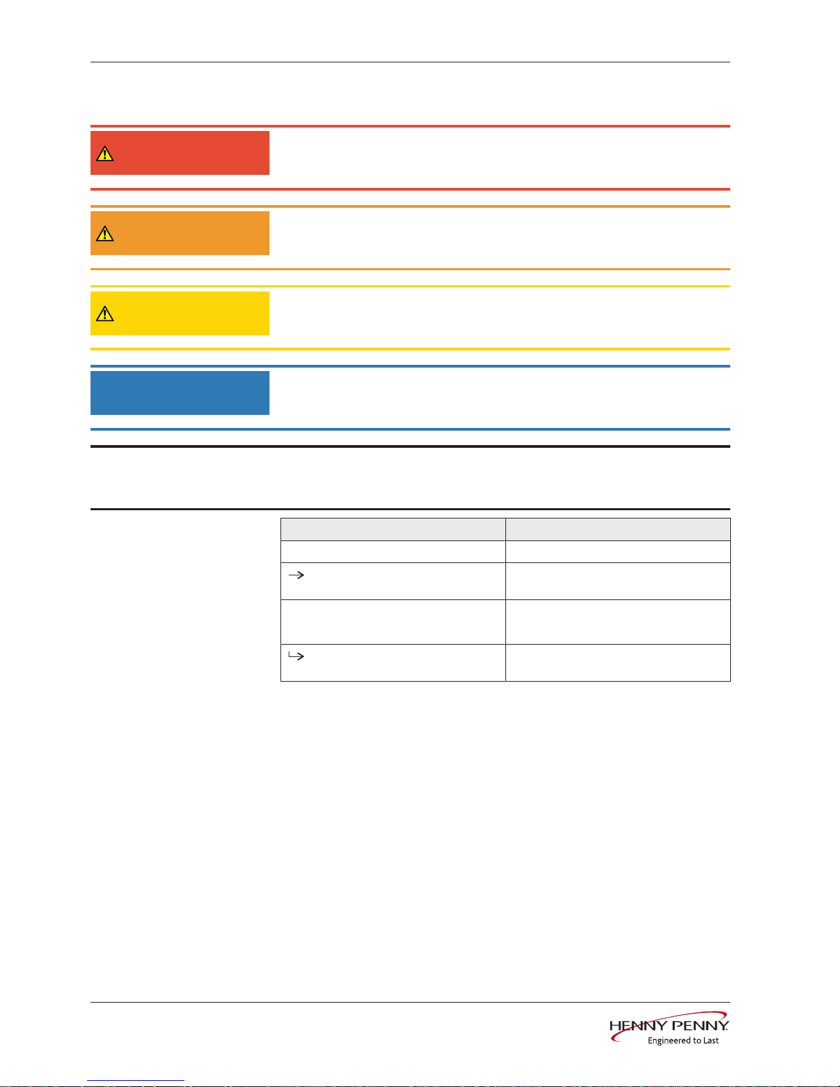
1.1.1 Explanation of signs
DANGER
Imminent danger
Failure to comply will lead to death or very severe injuries.
WARNING
Potential danger
Failure to comply can lead to death or very severe injuries.
CAUTION
Dangerous situation
Failure to comply can lead do slight to moderately severe injuries.
NOTICE
Property damage
Failure to comply can cause property damage.
INFORMATION
Information
Notes for better understanding and operation of the unit.
Symbol / sign Meaning
• Listing of information.
Action steps which can be performed in
any sequence.
1.
2.
Action steps which must be performed
in the specified sequence.
Result of an action performed or
additional information relating to it.
FM08-639-A
Introduction
7Installation instructions
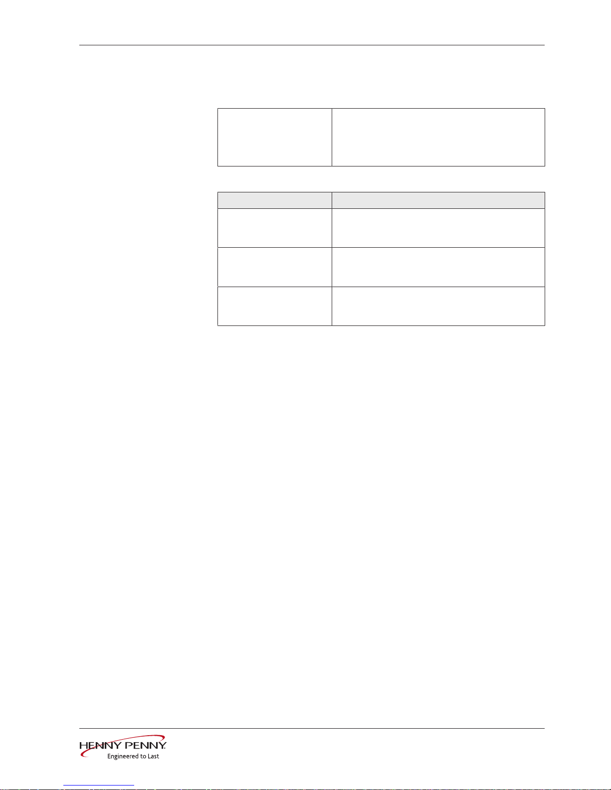
1.2 Personnel qualifications
Explanation of qualification
Skilled personnel • A skilled person is someone who, on the basis of
their technical training, knowledge and experience
as well as familiarity with the applicable standards,
can assess the assigned work and recognize possible dangers.
Type of activity Qualification
Electrical connection • Electrician
• Specialized training
• Employee of the responsible technical company
Water connection • Water specialist
• Specialized training
• Employee of the responsible technical company
Waste water connection • Waste water specialist
• Specialized training
• Employee of the responsible technical company
1.3 Use of the unit
This unit is intended to be used solely for commercial purposes,
particularly in commercial kitchens.
1.4 Warranty
The warranty is void and safety is no longer assured in the event of:
• Improper conversion or technical modifications of the unit,
• Improper use,
• Improper startup, operation or maintenance of the unit,
• Problems resulting from failure to observe these instructions.
FM08-639-A

Safety instructions
8 Installation instructions
2 Safety instructions
The unit complies with applicable safety standards. Residual risks
associated with operation or risks resulting from incorrect operation
cannot be ruled out and are mentioned specifically in the safety
instructions and warnings.
The installation fitter must be familiar with regional regulations and
observe them.
The installation fitter must observe the safety instructions in these
installation instructions and in the "Safety information" chapter of the
operating instructions.
Ensuring conformity with
standards
Observe applicable international, European and national laws,
regulations, standards and directives for the unit when transporting,
setting up and connecting it.
Improper installation Risk of property damage and personal injury from improper
installation
• Install the unit only as specified in these installation instructions.
• Do not add anything to the unit or modify the unit.
• Use only original spare parts.
Transportation and storage Risk of personal injury and property damage from improper
transportation and improper storage
• Store the unit in a dry, frost-free environment.
• Observe the safety regulations for the lifting gear used.
• Attach the unit to the lifting gear securely during transport and
installation, and prevent it from dropping.
• Transport the unit in an upright position, do not tilt or stack.
• Pay attention to protruding parts when transporting the unit
without packaging.
Fire prevention Risk of fire from combustible surfaces
• Observe general fire prevention regulations.
Organizational measures Risk of property damage and personal injury from lack of
organizational measures
• Identify danger zones when transporting, installing and connecting
the unit.
• Prior to starting the installation tasks, notify any operator present
about the procedure.
• Prior to starting the installation task, discuss how to behave in an
emergency.
• Use equipment and protective gear suitable for the activity.
• Brace housing components to prevent them from falling over and
dropping.
FM08-639-A

Safety instructions
9Installation instructions
Installation Risk of property damage and personal injury from improper
installation
• Ensure that the installation area has adequate load-bearing
capacity.
• Wear safety shoes and protective gloves.
Electrical connection Risk of fire from improper connection
• Observe applicable regional regulations of the electric supplier.
• Ensure that only electricians licensed by the electric supplier
connect the unit.
• Ensure that the electrical system is earthed by a protective
earthing conductor.
• Note the information on the nameplate.
Danger of electric shock from live components.
• Prior to working on the electrical system, switch off the unit,
disconnect the electrical system from the mains and prevent
power from being switched on again. Check to ensure the system
is dead.
• Use only insulated tools.
Commissioning Risk of property damage and personal injury from improper
commissioning
• Read the operating instructions prior to commissioning. Observe
the safety instructions in these installation instructions and in the
"Safety information" chapter of the operating instructions.
• Only put the unit into service after a successful function test in its
assembled state.
• Put the unit into service only after it has reached room
temperature.
• Observe the units during operation.
FM08-639-A
Description of the unit
10 Installation instructions
3 Description of the unit
3.1 Overview of the unit
a
b
c
d
e
f
g
h
i
j
k
l
m
n
o
p
q
r
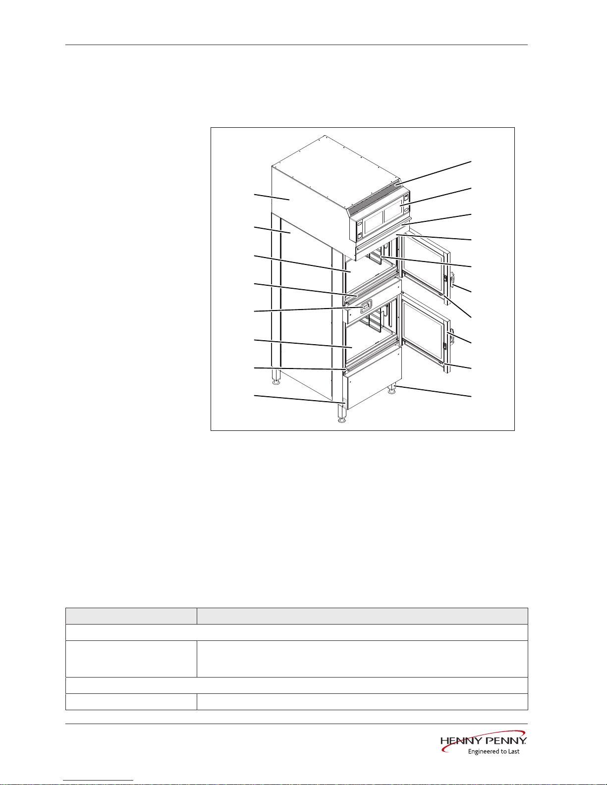
Image: Floor-standing unit
a Air outlet j Unit leg
b Operating unit k Nameplate
c Filter drawer l Discharge channel for bottom unit
d Condensate baffle m Cooking chamber in bottom unit
e Hang-in frame n Hand shower (optional)
f Door handle o Discharge channel for top unit
g Discharge channel for top door p Cooking chamber in top unit
h Cooking chamber door q Housing
i Discharge channel for bottom
door
r Recirculation hood
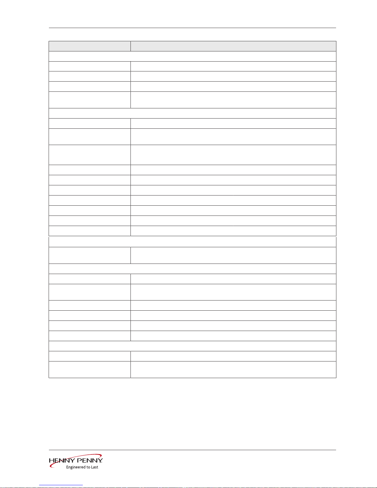
3.2 Unit and connection data
Size 610
Dimensions
Unit
Length x Width x Height (mm
(in))
550 (21,65) x 880 (34,65) x 1908 (75,12)
Weight
Unit (kg (lb)) 220 (485,1)
FM08-639-A
Description of the unit
11Installation instructions
Size 610
Emissions
Noise level (db(A)) < 65
Operating environment
Temperature (°C (°F)) 5 (41 ) — 40 (104 )
Relative air moisture (%)
non-condensing
95
Electrical connection
Protection class IPX5
Connection terminal (mm²
(sqin))
16 (0,0248)
Connection line One connection line
Type of connection 3PE AC 50/60 Hz, 3NPE AC 50/60 Hz
Voltage (V) 208
Connected load (kW) 14,8
Fuse (A) 50
Voltage (V) 240
Connected load (kW) 19,6
Fuse (A) 50
Power optimization system
Connection terminal (mm²
(sqin))
2,5 (0,0039)
Softened drinking water connection
Type of water Softened drinking water, cold
Carbonate hardness CaCO
3
(mmol/l (ppm))
< 0,9 (90 ppm)
Chloride Cl (mg/l) < 100
Iron Fe (mg/l) < 0.2
Connection pressure (kPa (psi)) 200 (29) — 600 (87)
Connection (") R 3/4 male thread
Drinking water connection
Type of water Drinking water, cold
Carbonate hardness CaCO
3
(mmol/l (ppm))
< 4 (400 ppm)
FM08-639-A
Description of the unit
12 Installation instructions
Size 610
Connection pressure (kPa (psi)) 200 (29) — 600 (87)
Connection (") R 3/4 male thread
Water consumption for steaming *
Softened drinking water (l/h
(gal/h))
20 (5,28)
Water consumption for combisteaming *
Softened drinking water (l/h
(gal/h))
4,4 (1,16)
Water consumption for WaveClean cleaning program *
Softened drinking water (l (gal)) 2,5 l (0,66)
Drinking water (l (gal)) 35 l (9,25)
Waste water connection
Waste water type Dirty water
Maximum length (m (ft)) 1 (3,3) with a drop of at least 5% or 3°
Temperature-resistant to (°C
(°F))
95 (203 )
Connection (mm (in)) 50 (1,97)
Maximum flow rate (l/min (gal/
min))
10 (2,64)
* Applies to both cooking chambers together
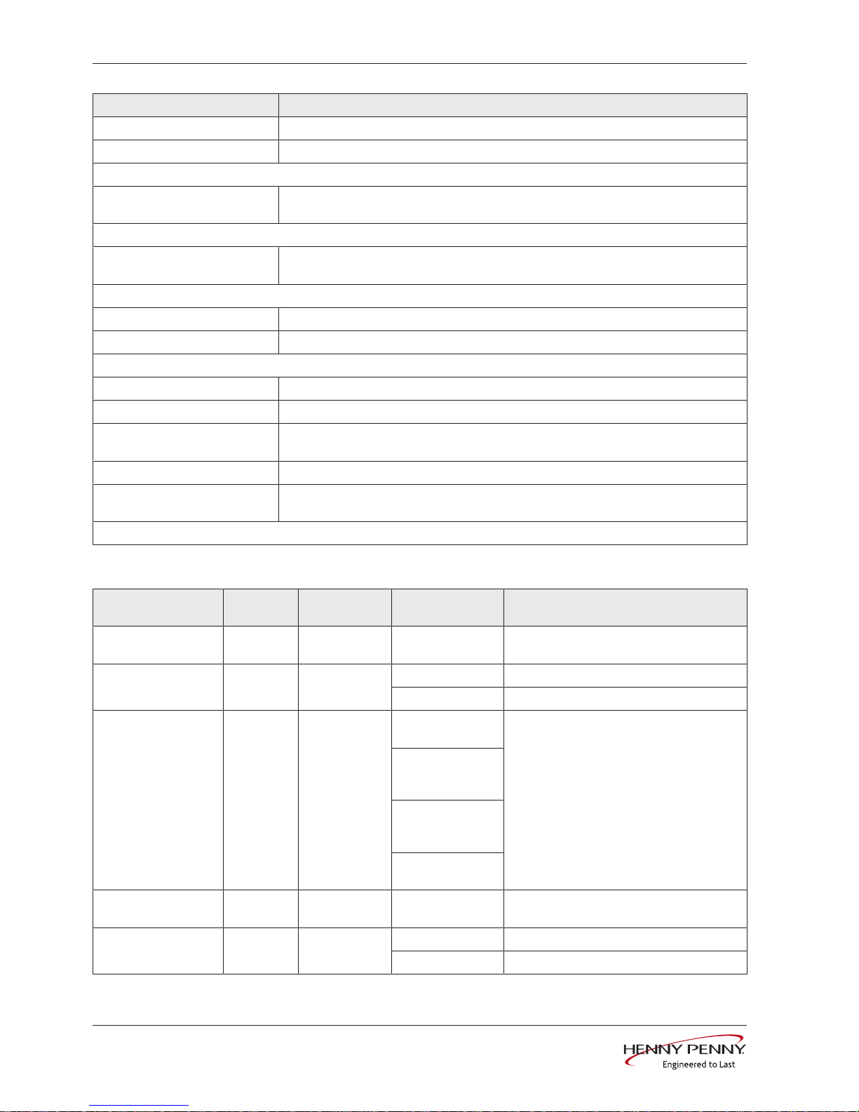
Basic setting of the control
Basic setting ParametersStandard
value
Range of
adjustment
Explanation
Supply voltage 14 400 100 — 500 V Enter the local, mean voltage between the
line conductors.
Date / time yyyy - mm - dd Year - Month - Day
hh : mm Hour : Minute
Altitude 2 0—999 0—999 m (3277
ft)
Request the altitude above sea level from
the local weather station. If the altitude is
unknown, enter 0—999 m (3277 ft).
1000 m (3280
ft)—1999 m
(6557 ft)
2000 m (6560
ft)—2499 m
(8197 ft)
2500 m (8200 ft)
or higher
Volume of audible
signal
Medium Individual Sets the volume.
Temperature unit
setting
1 °C °C Celsius (°C)
°F Fahrenheit (°F)
FM08-639-A
 Loading...