

Henny Penny FPG-615, FPG-121, FPE-121, FPE-215, FPG-215 Service Instructions Manual
...
FlexFusion® ELECTRIC
& GAS PLATINUM
COMBI
Service instructions
Model
FPE-615 FPG-615
FPE-621 FPG-621
FPE-115 FPG-115
FPE-121 FPG-121
FPE-215 FPG-215
FPE-221 FPG-221
Translation from the original document • FM06-101A DE • 8/26/2019
FM06-101A
en-US
Henny Penny Corporation
P.O.Box 60
Eaton,OH 45320
USA
Phone +1 937 456-8400
Fax +1 937 456-8402
Toll free in USA
Phone +1 937 417-8417
Fax +1 937 417-8434
www.hennypenny.com
2 Service instructions

Directory of contents
1Password overview ............................................................ 7
2Introduction......................................................................... 8
2.1About this manual ............................................................................ 8
2.2Warranty............................................................................................ 8
3Safety instructions ............................................................. 9
4Description of operation.................................................. 10
4.1DynaSteam...................................................................................... 10
4.2WaveClean ...................................................................................... 11
5Opening and closing the unit.......................................... 13
5.1Control panel .................................................................................. 13
5.1.1Opening the control panel ....................................................................... 13
5.1.2Closing the control panel......................................................................... 13
5.2Side wall .......................................................................................... 14
5.2.1Removing the side wall ........................................................................... 14
5.2.2Attaching the side wall............................................................................. 14
6Component overview ....................................................... 15
6.1Platinum operating panel / control ............................................... 15
6.2Gold operating panel / control ...................................................... 16
6.3FGE/ FPE 6xx 1xx Electric, left side ............................................. 17
6.4FGE/ FPE 2xx Electric, left side .................................................... 19
6.5FGG/ FPG 6xx 1xx Gas, left side................................................... 20
6.6FGG / FPG 2xx Gas, left side......................................................... 22
6.7FGG/ FPG 6xx 1xx, right side ........................................................ 24
6.8FGG/ FPG 2xx, right side ............................................................... 25
7Service menu - appliance test......................................... 26
7.1Service menu .................................................................................. 26
7.1.1Calling up the service level...................................................................... 26
7.1.2Service menu overview ........................................................................... 26
7.2Appliance information.................................................................... 27
7.3Status information.......................................................................... 28
7.4CombiDoctor................................................................................... 31
7.5Relay test ........................................................................................ 34
7.6WaveClean Test.............................................................................. 36
7.7100°C + core temperature calibration........................................... 37
7.7.1Checking the calibration - single-chamber appliance 6.x / 10.x .............. 38
7.7.2Checking the calibration - two-chamber appliance 20.x.......................... 39
7.7.3Calibrating the cooking chamber sensor - single-chamber appliance 6.x /
10.x................................................................................................................... 40
7.7.4Calibrating the cooking chamber sensor - two-chamber appliance 20.x. 41
FM05-16--
3Service instructions

Directory of contents
7.8DynaSteam test .............................................................................. 42
7.9Emptying the water ........................................................................ 43
7.10Data and time................................................................................ 43
7.11Installation height......................................................................... 44
7.12Audio settings .............................................................................. 44
7.13Select signal tones....................................................................... 45
7.14POS activation (only for electric energy type)........................... 45
7.15Exporting log data........................................................................ 45
7.16Software update ........................................................................... 46
7.17Importing additional content....................................................... 46
7.18Restoring data .............................................................................. 47
7.19Backing up data............................................................................ 47
7.20Water filter maintenance.............................................................. 48
7.21Importing contact data................................................................. 48
7.22Setting units.................................................................................. 49
7.23Backup relay ................................................................................. 49
7.24Settings parameters..................................................................... 51
7.24.1Selecting and changing parameters...................................................... 51
7.24.2Parameter overview .............................................................................. 51
7.25Backing up the SD card ............................................................... 53
7.26Restoring the SD card.................................................................. 53
7.27Background lighting..................................................................... 54
7.28Hour meter .................................................................................... 54
7.29Status overview direct access .................................................... 54
8Software ............................................................................ 55
8.1Software update ............................................................................. 55
8.2Importing additional content......................................................... 57
8.3Importing the manufacturer's cookbook...................................... 59
9Trade show mode............................................................. 61
10Electronics ...................................................................... 62
10.1Overview of the controller ........................................................... 62
10.2Layout of the control board......................................................... 63
10.3Configuration of the control board............................................. 64
10.4 Safety overview ........................................................................... 66
11Gas technology .............................................................. 68
11.1Basic principles............................................................................ 68
11.2CO2 setting ................................................................................... 69
11.2.1Opening the Setting menu..................................................................... 69
11.2.2Adjusting the settings (CO2 calibration) ................................................ 70
11.3Converting the gas type .............................................................. 76
4 Service instructions
FM05-16--

Directory of contents
11.4Checking the connection pressure ............................................ 78
11.5Checking the offset pressure...................................................... 80
12Gas orifices and C02 values up to S/N 16212355........ 82
13Gas orifices and C02 values after S/N 16212356......... 83
14Fault messages & troubleshooting............................... 84
14.1Overview ....................................................................................... 84
14.2Symbols for errors ....................................................................... 85
14.3Emergency operation................................................................... 87
14.4Temperature sensor area ............................................................ 88
14.4.1Cooking chamber sensor defective (694, 695)...................................... 88
14.4.2Top cooking chamber sensor defective (696, 728) ............................... 89
14.4.3Bottom cooking chamber sensor defective (697, 729) ......................... 90
14.4.4Core temperature sensor defective (699, 700)...................................... 91
14.4.5Internal core temperature sensor defective (714, 716) ......................... 92
14.4.6External core temperature sensor defective (715, 717) ........................ 92
14.4.7Water vapor sensor defective (710) ...................................................... 93
14.4.8Siphon temperature very high (SOF_ID20, ID21) ................................. 94
14.4.9Risk of frost (TMP_ID72, MMI_ID51)..................................................... 94
14.4.10Excess temperature in the cooking chamber (ID18, ID73).................. 95
14.5Motor area ..................................................................................... 96
14.5.1Overview ............................................................................................... 96
14.5.2Fan defective or temperature limiter triggered (702) ............................. 98
14.5.3Fan defective. Cooking program was cancelled (701) ........................ 100
14.5.4Top fan defective. Automatic switching to emergency operation (703, 705)
....................................................................................................................... 100
14.5.5Bottom fan defective. Automatic switching to emergency operation (704,
706) ................................................................................................................ 101
14.5.6FAN_ID23: Fan error: Attempt to restart ............................................. 103
14.5.7FAN_ID24: Upper fan fault: Attempt to restart..................................... 103
14.5.8FAN_ID25: Lower fan fault: Attempt to restart..................................... 103
14.6Water area ................................................................................... 105
14.6.1Water pressure too low (709) .............................................................. 105
14.6.2Water pressure during WaveClean too low......................................... 107
14.7Electronics / control area .......................................................... 108
14.7.1Overtemperature control (TMP_ID2) ................................................... 108
14.7.2Critical temperature in the electronics (MMI_ID50) ............................. 109
14.7.3Failure to access external EEPROM (SOF_ID12)............................... 110
14.7.4Faulty CAN connection........................................................................ 110
14.7.55007: Not enough storage space for software update ........................ 110
14.7.65008: No new version found................................................................ 110
14.7.75009: The application could not be started. Application is restarting. . 111
FM05-16--
5Service instructions

Directory of contents
14.7.85010: The application could not be started. Restore configuration
backup?.......................................................................................................... 111
14.7.95013: Application could not be restored! Restore to factory settings with
OK. ................................................................................................................. 111
14.7.10Unit was restarted after power failure................................................ 112
14.7.11Door is open - cooking program was stopped................................... 112
14.8Gas area ...................................................................................... 114
14.8.1No gas (OTH_ID1)............................................................................... 114
14.8.2No gas (top)(OTH_ID2) ....................................................................... 116
14.8.3No gas (bottom)(OTH_ID3) ................................................................. 116
14.8.4No flame (OTH_ID4)............................................................................ 116
14.8.5No flame (top)(OTH_ID5) .................................................................... 116
14.8.6No flame (bottom)(OTH_ID6) .............................................................. 117
14.8.7Communication fault between I/O and ignition electronics (OTH_ID25) .....
117
14.8.8Communication fault between I/O and ignition electronics (top)
(OTH_ID26) .................................................................................................... 118
14.8.9Communication fault between I/O and ignition electronics (bottom)
(OTH_ID27) .................................................................................................... 118
14.8.10GAS_ID13: Flame fault during operation........................................... 119
14.9Testing the gas components..................................................... 119
14.9.1Checking the electrodes...................................................................... 119
14.9.2Inspection of the gas solenoid valve ................................................... 120
14.9.3Testing the heat exchanger................................................................. 121
6 Service instructions
FM05-16--
1 Password overview
Range Password Description Described in
Password overview
Installation /
commissioning
CO2 gas calibration 999 Verification and calibration of
Network settings 2000 Input network addressing. Only
Basic settings / user 111 Setting of basic values for the
Lockscreen 369 Deactivating the lockscreen in
Trade show mode 888 Activation / deactivation for
Service menu with
CO2 gas calibration
2100 Setting all basic parameters (for
example time / date).
exhaust emissions. Only for
energy type - gas.
for units with touchscreen control.
user, functions, software update.
cooking mode. Only for units with
touchscreen control.
exhibition mode.
1967 Service range for authorized
service technicians.
Installation instructions
Installation instructions
Installation instructions
Operating instructions
Operating instructions
Service instructions
Service instructions
FM05-16--
7Service instructions

Introduction
2 Introduction
2.1 About this manual
Target group Target group for this service manual is qualified personnel who are
Figures All figures in this service manual are intended as examples.
Spare parts To ensure the reliability of the unit and the individual components, it is
This service manual contains information needed by the service
technician for professional and correct fault isolation, repair and
maintenance of the unit. The service technician must also observe
the contents of the installation instructions and the user manual.
familiar with the technical functioning and operation of the unit.
Discrepancies can arise between this and the actual unit.
essential that only genuine OEM parts be used.
Spare parts can be identified exactly with the aid of the online
database.
2.2 Warranty
The warranty is void and safety is no longer assured in the event of:
• Modifications or technical changes to the unit,
• Improper use,
• Incorrect startup, operation or maintenance of the unit,
• Problems resulting from failure to observe these instructions.
8 Service instructions
FM05-16--
3 Safety instructions
For servicing tasks, the service technician must be familiar with and
observe regional regulations.
In addition, the notes in the service manual must be observed.
Safety instructions
DANGER
DANGER
Danger to life due to electric current
ü Disconnect power prior to performing gas and electrical work.
• Disconnect unit from the mains supply and secure it against restart.
• Check to ensure absence of voltage.
Risk of fatal injury from gas
ü Disconnect the unit from gas supply prior to performing gas installation
tasks.
• Lock site gas supply and secure it against restart.
FM05-16--
9Service instructions
Description of operation
a
b
c
d
e
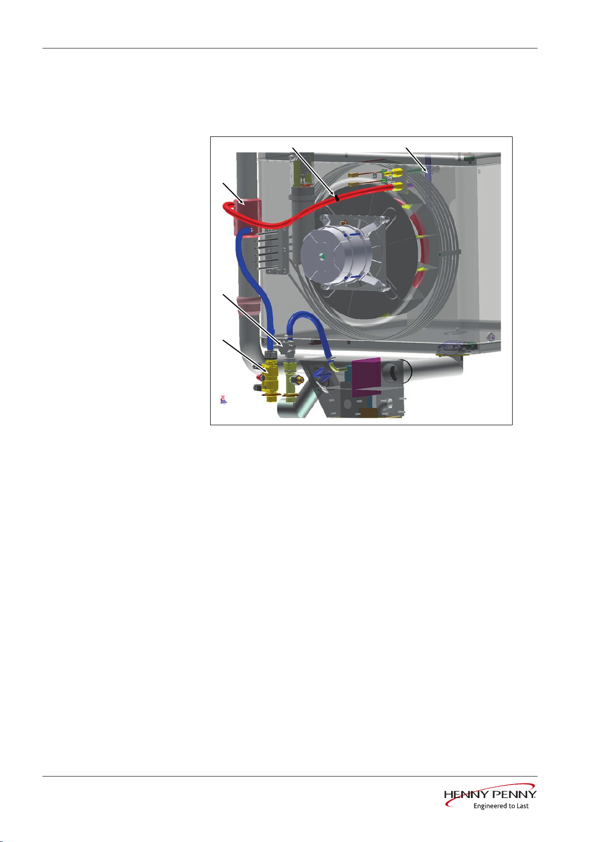
4 Description of operation
4.1 DynaSteam
Overview
a Steaming appliance with pressure
switch
b Magnetic valve water vapor
elimination
c Heat exchanger (up to approx.
50°degrees)
d Reduction
e Water supply pipe
Description • The electronics control the DynaSteam steaming appliance. They
regulate the water quantity for generating steam. DynaSteam
guarantees, regardless of the water pressure, the precise supply
of the required quantity of water. The prerequisite for this is a
customer-supplied water flow pressure between 2 and 6 bar. The
water pressure is monitored using a pressure switch.
• The DynaSteam steaming appliance cannot be calibrated and is
completely electronically controlled.
• The heat exchange heats the water in advance up to 50°C. The
heat from the exhaust pipe is used for this.
• The water comes through the water supply pipe to the fan impeller
in the cooking chamber. The fan impeller creates small water
drops, which evaporate in the hot oven atmosphere. The water
evaporates in the cooking chamber and on the fan impeller. The
tapering of the hose stabilizes the water flow of the pulsing
steaming unit.
10 Service instructions
FM05-16--
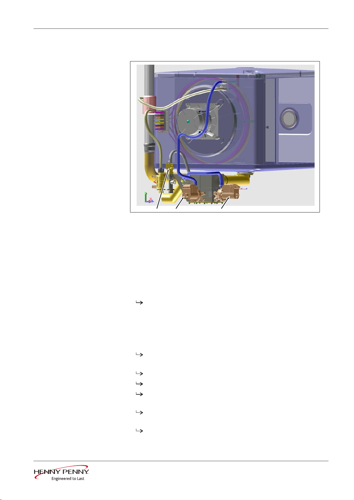
4.2 WaveClean
a b c
Functional overview
Description of operation
a Magnetic valve K12 c Pump G24
b Pump G16
The following purification stages are available on the fully automatic
cleaning WaveClean:
• Short: duration of about one hour
• Normal: duration about two hours
• Extra: duration approximately three hours
Description 1. Testing the cooking chamber temperature.
Automatic cooling of the cooking chamber, if > 55°C.
2. Inserting the WaveClean cartridge.
3. Water exchange of siphon content by the siphon pump G24 and
solenoid valve K12.
4. Circulation of water by means of pump G16. Thus pre-cleaning of
the cooking chamber. Then anew siphon water exchange.
The heater heats the oven to 55°C.
5. Start cleaning.
Fan motor and WaveClean pump G16 active.
Heating active. Heating the cooking chamber to about 70°C.
FM05-16--
The first layer of wax melts in the WaveClean cartridge. The
cleaner falls into the cooking chamber and mixes with water.
The fan motor operates in both directions of rotation and at
different speeds.
The cleaning phase duration depends on the selected
program.
11Service instructions
Description of operation
INFORMATION
6. A new water exchange of siphon content by means of the siphon
pump G24 and solenoid valve K12.
7. Start of rinsing.
Identical to step 5 (cleaning).
Differences: Heating of the cooking chamber to 92°C. The
second layer of wax melts in the WaveClean cartridge. The
rinse agent drops into the cooking chamber and mixes with
water.
Final rinse to bring the pH value to the normal level.
8. In the programs "normal" and "extra" additional drying of the
interior occurs by means of hot air.
9. Finally, an indicator for withdrawing the WaveClean cartridge
appears, and has to be confirmed.
Despite different cleaning durations, all cleaning steps require the same
amount of water.
During the cleaning process about 3 liters of water are provided by the steam-
WaveClean termination
INFORMATION
ing unit into the oven.
WaveClean forced rinsing
The WaveClean forced rinse is automatically started by the operator in case of
failure or premature termination. The duration is 12 minutes. An entry is made
into the HACCP and in the diagnostic memory.
12 Service instructions
FM05-16--
5 Opening and closing the unit
a
c
b
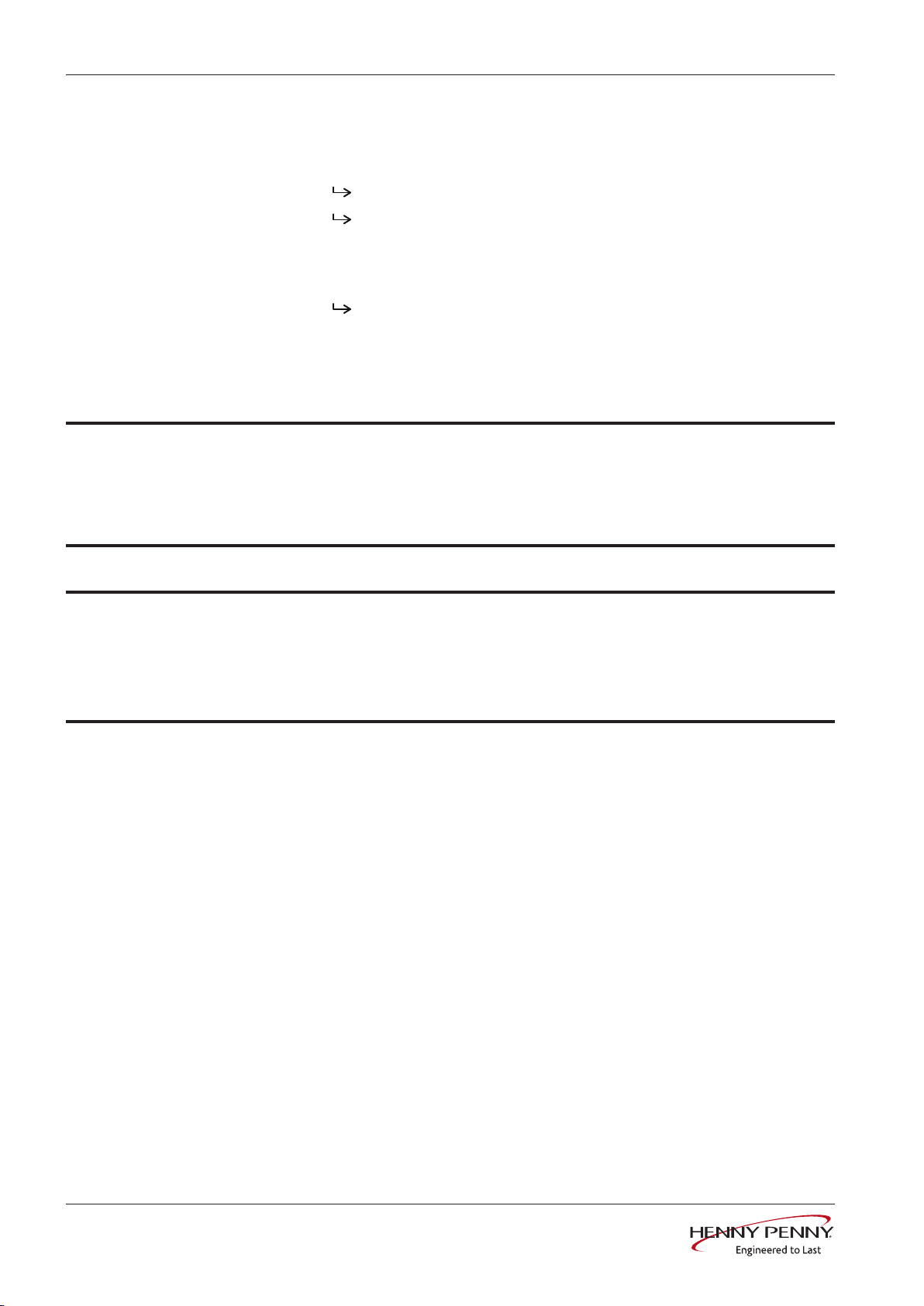
5.1 Control panel
Opening and closing the unit
Image: Opening the control panel
a Lock (cam) b Operating panel
c Hex key
5.1.1 Opening the control panel
1. Insert hex key (5 mm ) into screw and turn it clockwise.
2. Withdraw the hex key.
5.1.2 Closing the control panel
Damage due to vapor / moisture
NOTICE
There should be no gap between the control panel and housing.
1. Press and hold operating panel on the left.
The operating panel is secured against unauthorized opening.
The operating panel is now unlocked.
The operating panel pops up automatically.
Repeat as many times as necessary.
The operating panel snaps in audibly.
FM05-16--
13Service instructions
Opening and closing the unit
BA
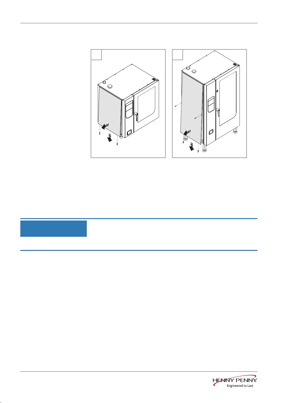
5.2 Side wall
Image: A Sizes 6.x and 10.x; B Size 20.x
5.2.1 Removing the side wall
1. Unscrew the screws in the side wall.
2. Pull the bottom edge of the side wall forwards.
3. Remove the side wall.
5.2.2 Attaching the side wall
NOTICE
Risk of property damage from leaky housing
• Check seals when attaching the housing parts.
• Replace damaged seals.
1. Insert top edge of side wall.
2. Carefully push the bottom of the side wall inward.
3. Secure the bottom of the side panel with screws.
4. Check that the side wall is in contact with the unit on all sides.
14 Service instructions
FM05-16--
6 Component overview
A2
S0
A3
B1
B15
A1
B20
E1
SD
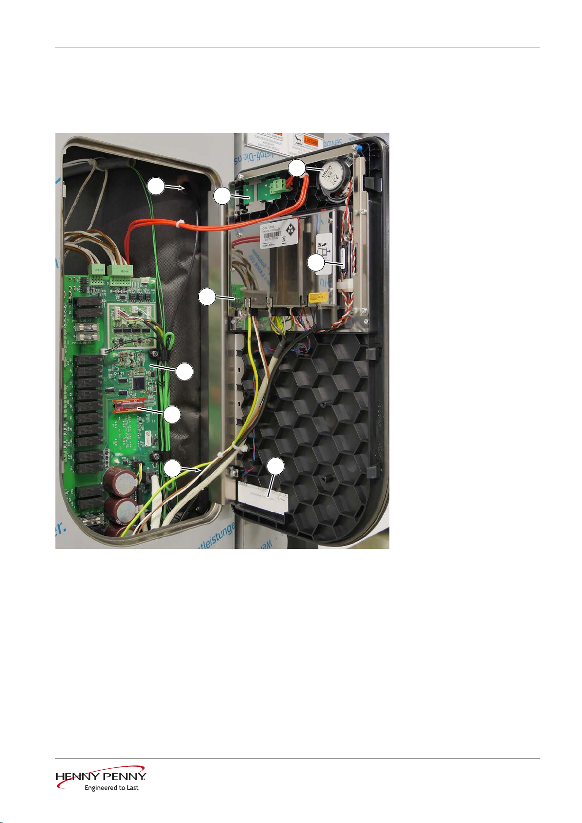
6.1 Platinum operating panel / control
Component overview
Image: Touch operating panel area - FKE/ FKG
A1 Control board A2 Operating panel
A3 Digital memory B1 Core temperature sensor
B15 Reed contact switch B20 Loudspeaker
E1 Insert with LED lighting S0 On / Off switch
SD SD card
FM05-16--
15Service instructions
Component overview
A2
S0
A3
B1
B15
A1
B20
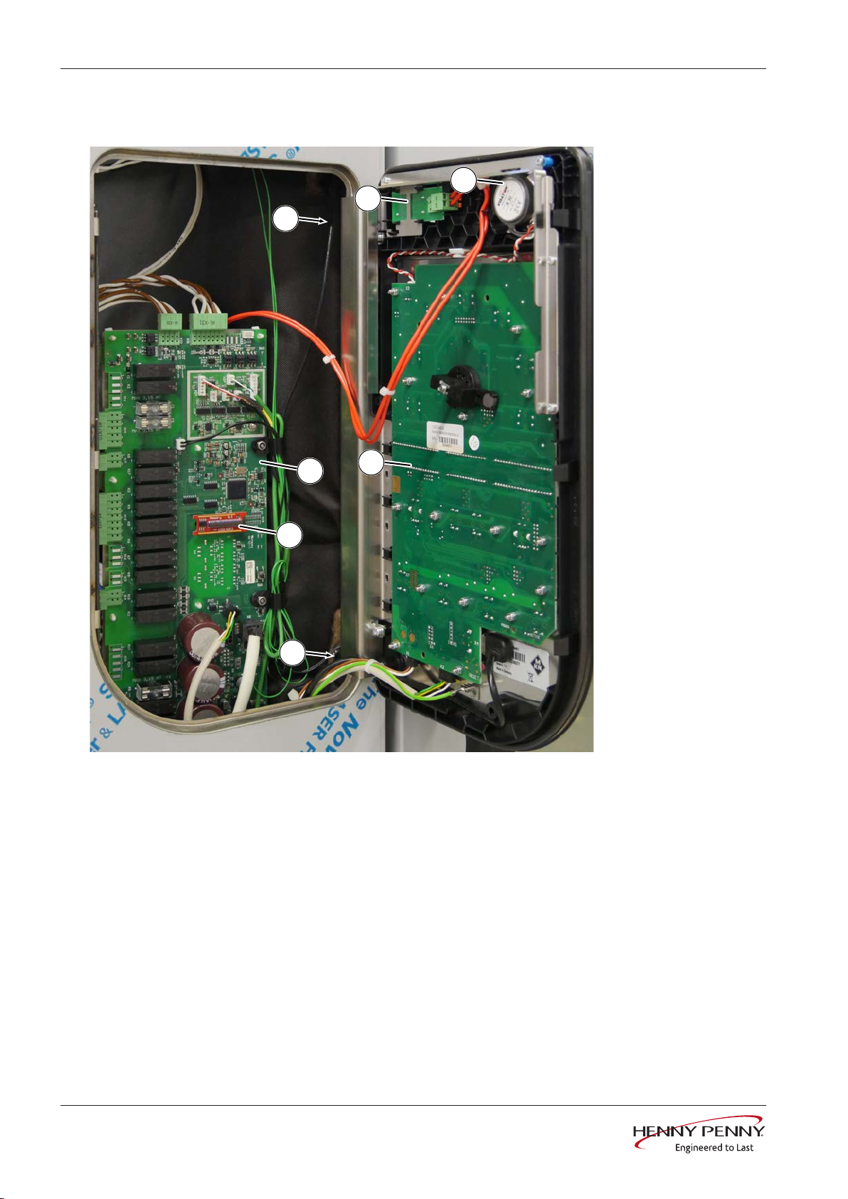
6.2 Gold operating panel / control
Image: Classic operating panel area - FKE/FKG
A1 Control board A2 Operating panel
A3 Digital memory B1 Core temperature sensor
B15Reed contact switch B20Loudspeaker
S0 On / Off switch
16 Service instructions
FM05-16--
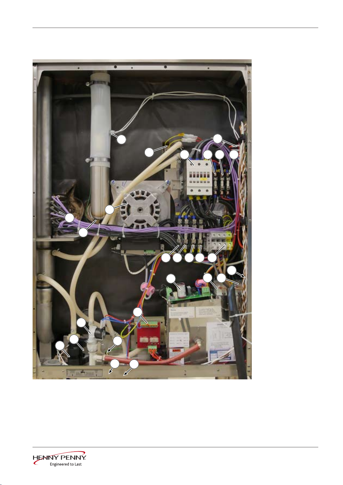
6.3 FGE/ FPE 6xx 1xx Electric, left side
Q1 F1
F4
X1
K12
G16
G24
T1
B5
B4
B11
E1
M10
K20
B14
T10
M8
G7
B13
F1
F1.1
F21
F22
F23
F24
Q2
Q3
Component overview
Image: FGE/ FPE UL - left side
FM05-16--
17Service instructions

Component overview
B4 Vapor sensor B5 Moisture sensor
B11Safety temperature limiter B13Thermal switch 50°C
B14Pressure switch F1 Fuse, 6A, slow-blow
F1.1Fuse, 6A, slow-blow F4 Fuse, 6A, slow-blow
F21 Fuse, 60A (only on 220) F22 Fuse, 60A (only on 220)
F23 Fuse, 60A (only on 220) F24 Fuse, 60A (only on 220)
G7 Cooling fan G16Circulation pump
G24Drain pump K12Solenoid valve (steam)
K20DynaSteam unit M8 Solenoid
M10Fan motor Q1 Main contactor
Q2 Solid-state relay (SSR), 100 A Q3 Solid-state relay (SSR), 100 A
T1 Transformer (supply) T10 Power pack for fan motor
X1 Power connection terminal
18 Service instructions
FM05-16--
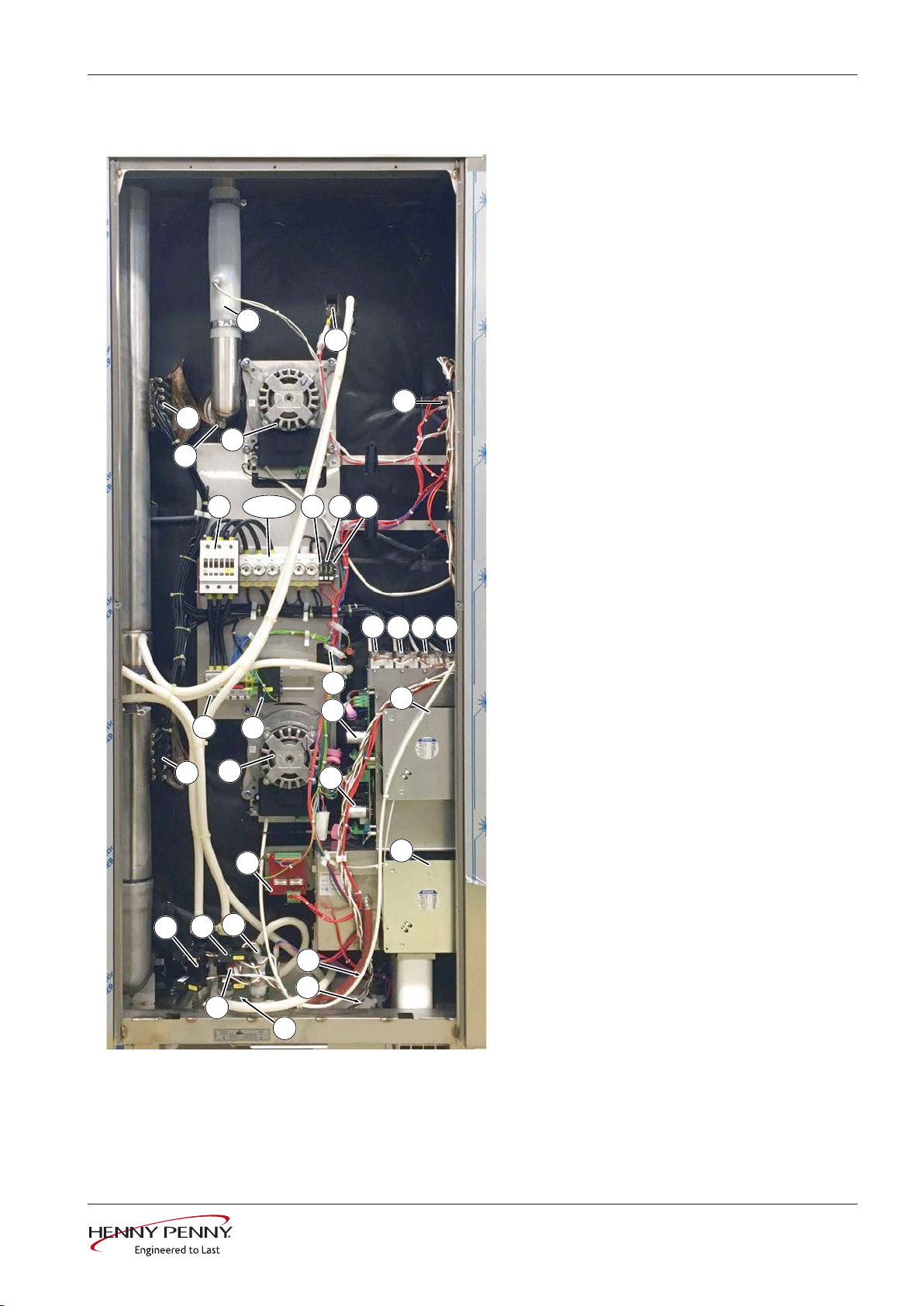
6.4 FGE/ FPE 2xx Electric, left side
B11
E1
M10
B5
R1
X1
F1Q1
M8
B13
G8
T1
B4
T10
B14
K20
K12
G24
G16
E2
K21
G7
M20
F2 F4
T20
Q2
F21-F23
B12
Q3 Q4 Q5
Component overview
B4 = Steam sensor
B5 = Moisture sensor
B11 = Safety temperature limiter
B12 = Safety temperature limiter
B13 = Thermal switch 50°C
B14 = Pressure switch
F1 = Fuse, 10A, slow-blow
F2 = Fuse, 10A, slow-blow
F4 = Fuse, 6.3A, slow-blow
F21-F23 = Fuse
G7 = Cooling fan (180 x 180 mm)
G8 = Cooling fan 180 x 180 mm)
G16 = Recirculation pump
G24 = Emptying pump
K12 = Solenoid valve (steam)
K20 = DynaSteam unit with pressure switch
K21 = DynaSteam unit without pressure switch
M8 = Solenoid
M10 = Fan motor
M20 = Fan motor
Q1 = Main contactor
Q2 = Solid-state relay (SSR), top
Q3 = Solid-state relay (SSR), top
Q4 = Solid-state relay (SSR), bottom
Q5 = Solid-state relay (SSR), bottom
R1 = Filter
T1 = Transformer (supply)
T10 = Power pack for fan motor (top)
T20 = Power pack for fan motor (bottom)
X1 = Mains connection terminal
FKG – View of left side
FM05-16--
19Service instructions
Component overview
Q1 F1 F4
X1
G10
K12
G16
G24
T1
R1B5
B4
B11
A10
RC1
B100
T2
M10
E10
K20
B14
T10
M8
G7
K30
B13
6.5 FGG/ FPG 6xx 1xx Gas, left side
Image: FGG/ FPG CSA - left side
20 Service instructions
FM05-16--

Component overview
A10 Ignition electronics B4 Vapor sensor
B5 Moisture sensor B11 Safety temperature limiter
B13 Thermal switch 50°C B14 Pressure switch
B100 Glow electrode E10 Ionization electrode
F1 Fuse 10A, slow-blow F4 Fuse 6A, slow-blow
G7 Cooling fan G10 Gas fan
G16 Circulation pump G24 Drain pump
K12 Solenoid valve (steam) K20 DynaSteam unit
K30 Gas magnetic valve M8 Solenoid
M10 Fan motor Q1 Main contactor
R1 Filter RC1 RC combination
T1 Transformer (supply) T2 Transformer for glow electrode
T10 Power pack for fan motor X1 Power connection terminal
FM05-16--
21Service instructions

Component overview
Q1 F1 F4
X1
G10
K12
G16
G24
T1
R1B5
B4
B11
A10
RC1
B100
T2
M10
E10
K20
B14
T10
M8
G7
K30
B13
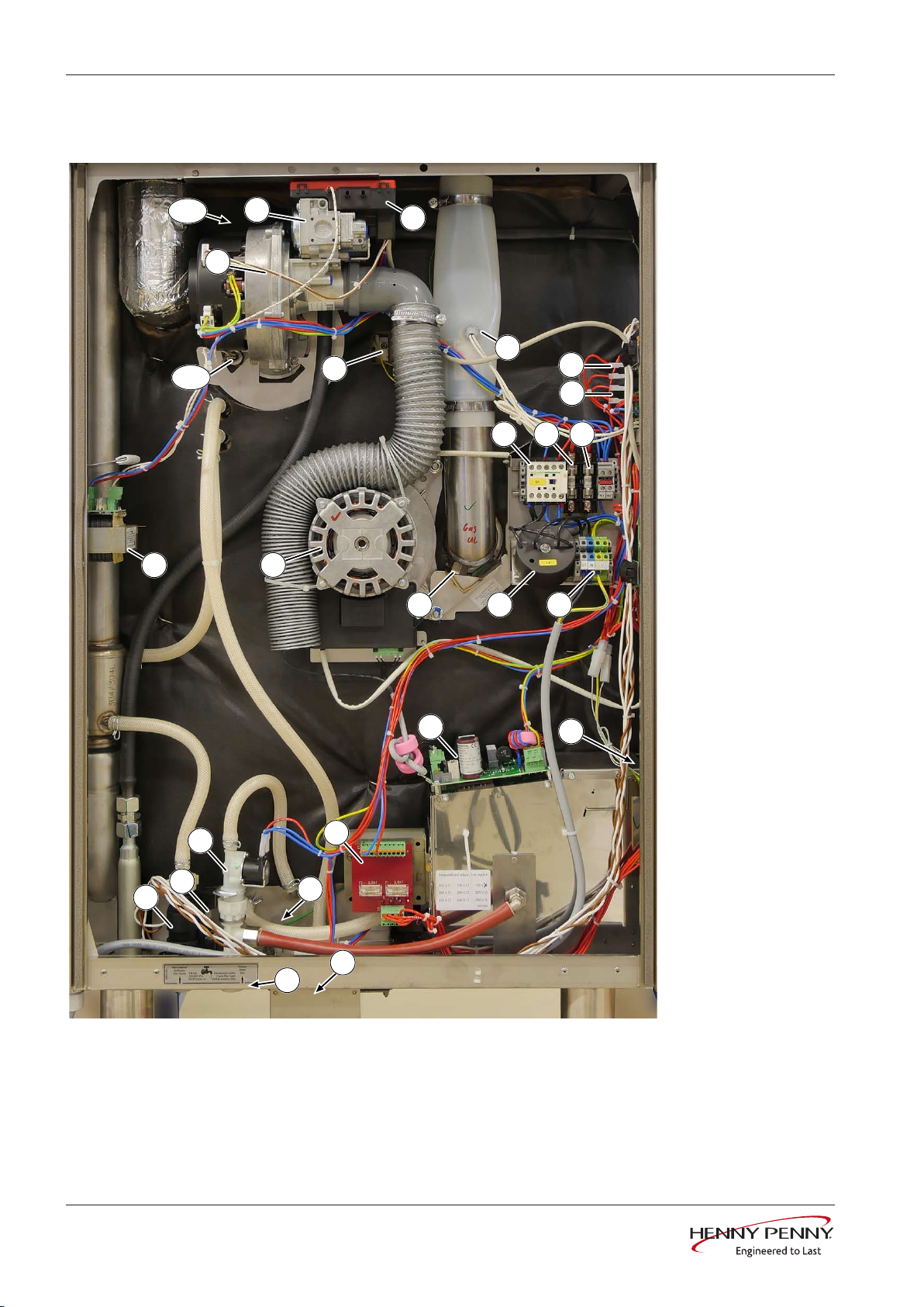
6.6 FGG / FPG 2xx Gas, left side
Image: FGG/ FPG CSA - left side
22 Service instructions
FM05-16--

Component overview
A10 Ignition electronics B4 Vapor sensor
B5 Moisture sensor B11 Safety temperature limiter
B13 Thermal switch 50°C B14 Pressure switch
B100 Glow electrode E10 Ionization electrode
F1 Fuse 10A, slow-blow F4 Fuse 6A, slow-blow
G7 Cooling fan G10 Gas fan
G16 Circulation pump G24 Drain pump
K12 Solenoid valve (steam) K20 DynaSteam unit
K30 Gas magnetic valve M8 Solenoid
M10 Fan motor Q1 Main contactor
R1 Filter RC1 RC combination
T1 Transformer (supply) T2 Transformer for glow electrode
T10 Power pack for fan motor X1 Power connection terminal
FM05-16--
23Service instructions
Component overview
E3
B2
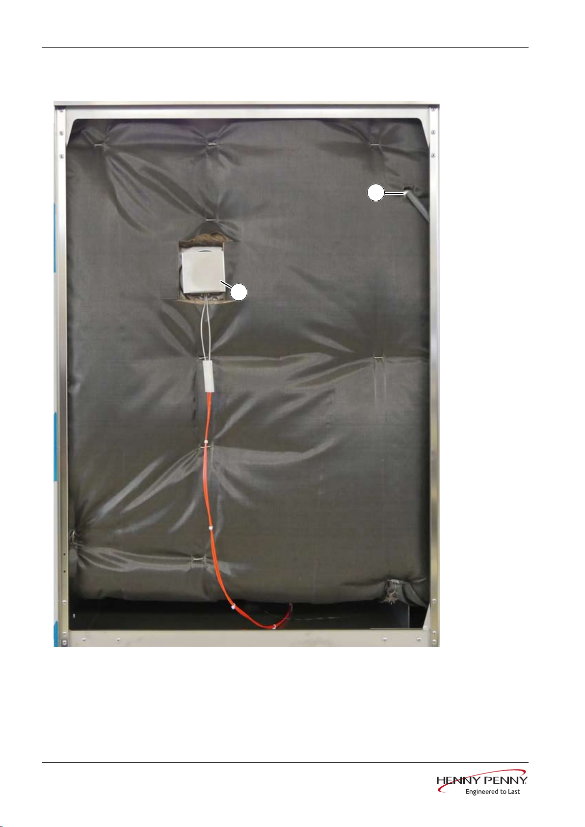
6.7 FGG/ FPG 6xx 1xx, right side
Image: FKE/ FKG – View of right side
B2 Cooking chamber sensors E3 Cooking chamber light
24 Service instructions
FM05-16--
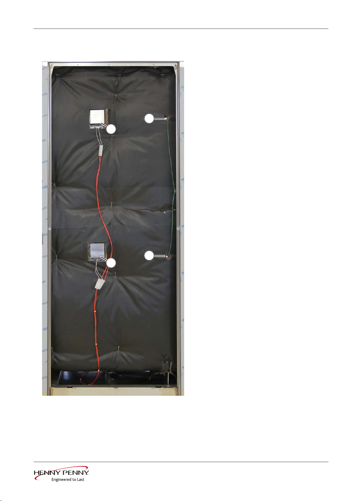
6.8 FGG/ FPG 2xx, right side
E3
B2
B3
E4
Component overview
B2 = To cooking chamber sensor
B3 = Bottom cooking chamber sensor
E3 = Cooking chamber light
E4 = Cooking chamber light
FKE/ FKG – View of right side
FM05-16--
25Service instructions
Service menu - appliance test
7 Service menu - appliance test
7.1 Service menu
Description • Functional testing of individual components
• Error analysis
• Maintenance
• Change basic settings
• Software update
The graphics shown may deviate due to changes and different
software versions.
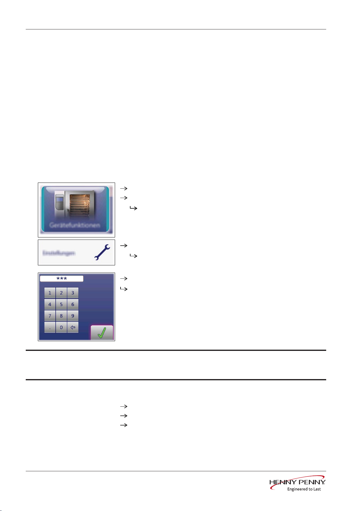
7.1.1 Calling up the service level
Calling up the Service menu
Switch the appliance on.
Touch the "Appliance functions" field.
INFORMATION
Display of
Touch "Settings" field.
Display of
Enter password and touch
Display of menu
The password for the service menu is 1967
Appliance functions
PIN
window.
Confirmation
Appliance test (Service menu)
menu.
field.
.
7.1.2 Service menu overview
Selecting a menu element
26 Service instructions
Display of the menu elements in the left area.
Page change by swiping upward/downward.
Select menu element by touching.
FM05-16--
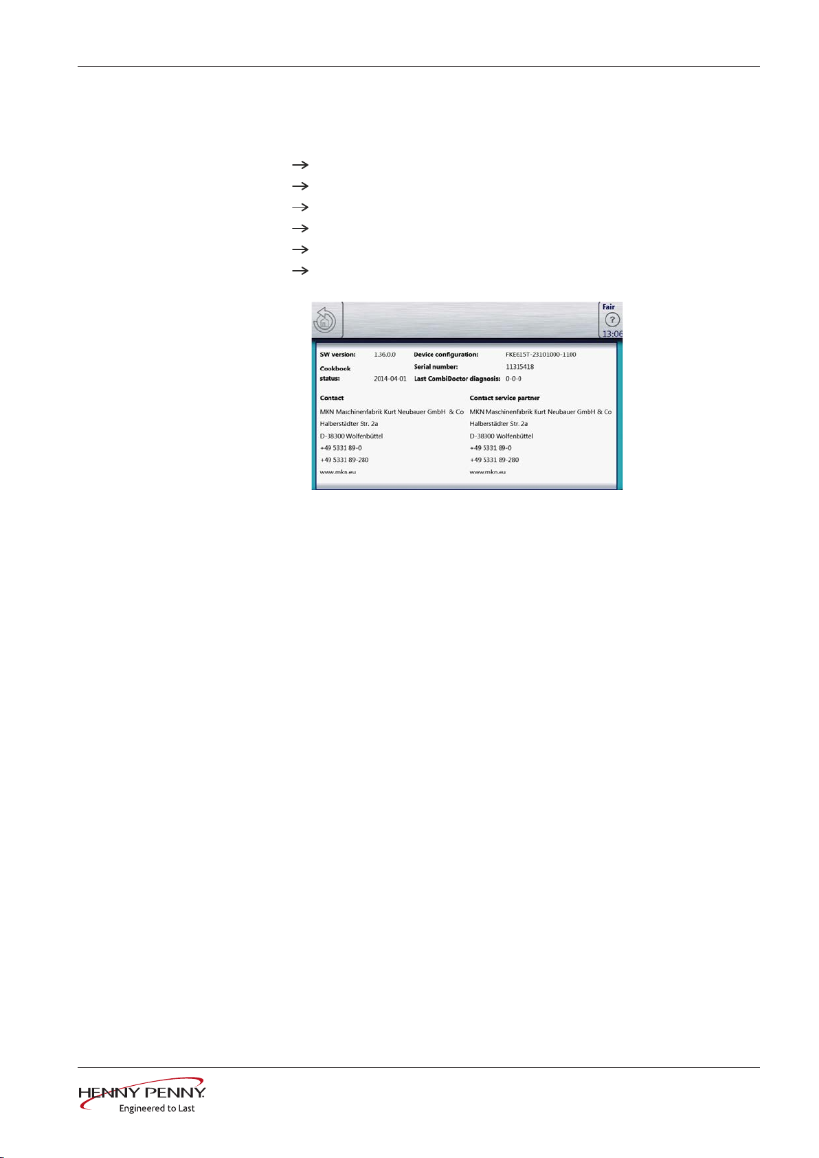
7.2 Appliance information
Description Display of the appliance-specific information
Overview
Service menu - appliance test
Software version
Cookbook version
Unit configuration
Serial number
Date of last CombiDoctor diagnosis.
Contact data
Exiting the appliance
information
Touch the
Back
field.
FM05-16--
27Service instructions
Service menu - appliance test
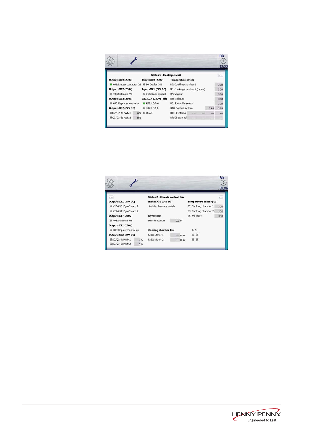
7.3 Status information
Status 1
Heating circuit
PWM Heat requirement in %.
POS Performance optimization system (option).
B3 Lower chamber sensor. Only present in 20.x floor-mounted
appliances.
Status 2
Climate control, fan
B14 Pressure switch on the DynaSteam unit
PWM Heat requirement in %.
M20 Bottom fan motor. Only present in 20.x floor-mounted appliances.
B3 Bottom cooking chamber sensor. Only present in 20.x floor-mounted
appliances.
28 Service instructions
FM05-16--
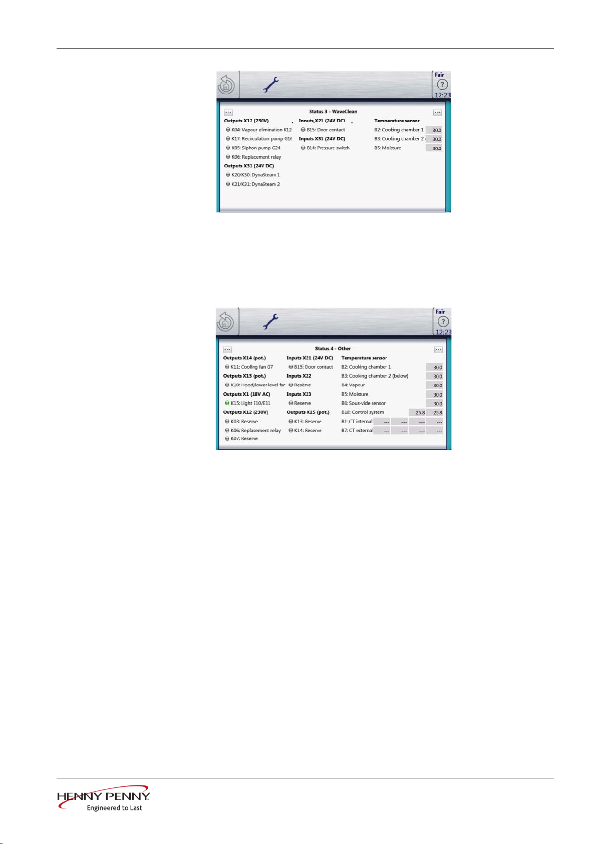
Status 3
WaveClean
Status 4
Service menu - appliance test
K04 Magnetic valve for water vapor elimination & siphon filling
B15 Reed contact switch
B14 Pressure switch on the DynaSteam unit
B3 Bottom cooking chamber sensor. Only present in 20.x pedestal unit
Miscellaneous
K10 Activation for optional condensation hood
B15 Reed contact switch
K03, K07 Not in use
K13, K14 Not in use
B3 Bottom cooking chamber sensor. Only present in 20.x pedestal unit
FM05-16--
29Service instructions
Service menu - appliance test
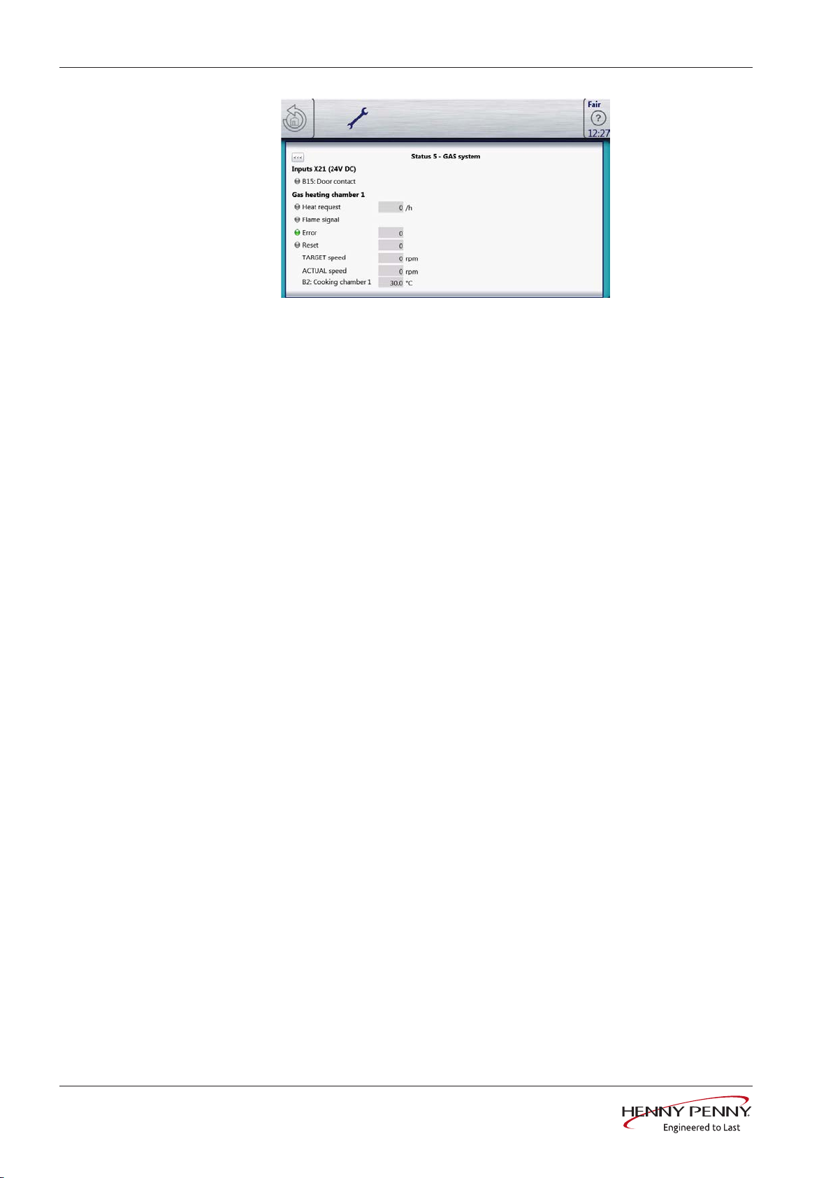
Status 5
Gas system
B15 Reed contact switch
Chamber 1 Top heating system
Chamber 2 Bottom heating system. Only present in 20.x pedestal unit
Flame signal Flame was detected by ionization electrode / ignition
electronics.
Error LED green if error was reported by the ignition electronics and
error number in the last hour.
Reset LED green if reset signal is sent by the I/O board to the ignition
electronics and error number in the last hour.
30 Service instructions
FM05-16--
 Loading...