

Henny Penny FlexFusion Gold 6.15, FlexFusion Gold 6.21, FlexFusion Platinum 6.21, FlexFusion Platinum 10.15, FlexFusion Platinum 10.21 Assembly Instructions Manual
...
Assembly instructions
R E G I S T E R W A R R A N T Y O N L I N E AT W WW. H E N N Y P E N N Y. C O M
Combi Steamer
Unit Model Type of
energy
FlexFusion
Platnium
FlexiFusion
Gold
6.15
6.21
10.15
10.21
20.15
20.21
Electric
Gas
Unit type
Tabletop unit
Pedestal unit
Translation from the original document • 10013865-0AMDE-- • 10/16/2015
10013865-0AMAE— en-US

Copyright
All rights to text, graphics and pictures in this documentation are held by MKN Maschinenfabrik Kurt
Neubauer GmbH & Co. KG. Distribution or duplication is exclusively permissible subject to a written
consent of MKN.
Copyright by MKN Maschinenfabrik Kurt Neubauer GmbH & Co. KG
Manufacturer
Copyright by MKN Maschinenfabrik Kurt Neubauer GmbH & Co. KG
Halberstaedter Strasse 2a
D-38300 Wolfenbuettel
Telephone 0 53 31 / 89-0
Telefax 0 53 31 / 89-280
2 Assembly instructions
Directory of contents
1MagicPilot Control Panel ................................................... 5
2Classic control panel ......................................................... 6
3Control board...................................................................... 7
4Cooking chamber sensors .............................................. 10
5Core temperature sensor................................................. 11
6Moisture sensor................................................................ 12
7Vapor sensor .................................................................... 13
8Reed contact switch......................................................... 14
9Pressure switch................................................................ 15
10Steaming unit.................................................................. 16
11Magnetic valve water vapor elimination....................... 17
12Solenoid .......................................................................... 18
13Power board for motor................................................... 19
14Semiconductor relay (SSR) ........................................... 20
15Fan motor........................................................................ 21
16Heating element.............................................................. 23
17WaveClean pump ........................................................... 25
17.1Circulation pump 6.x, 10.x........................................................... 25
17.2Circulation pump 20.x.................................................................. 26
17.3Drain pump 6.x, 10.x .................................................................... 27
17.4Drain pump 20.x ........................................................................... 28
18Cooling fan...................................................................... 29
19Control transformer........................................................ 30
20Door latch........................................................................ 31
20.1Door latch 6.x, 10.x....................................................................... 31
20.2Door latch 20.x.............................................................................. 32
21Cooking chamber door .................................................. 33
22Cooking chamber light................................................... 34
23Transformer glow electrode .......................................... 35
10013865-0AMAE—
3Assembly instructions

Directory of contents
24Gas solenoid valve......................................................... 36
25Gas fan ............................................................................ 38
26Gas burner ...................................................................... 40
27Glow and ionization electrodes .................................... 42
28Gas heat exchanger ....................................................... 44
29Gas burner pipe.............................................................. 46
4 Assembly instructions
10013865-0AMAE—
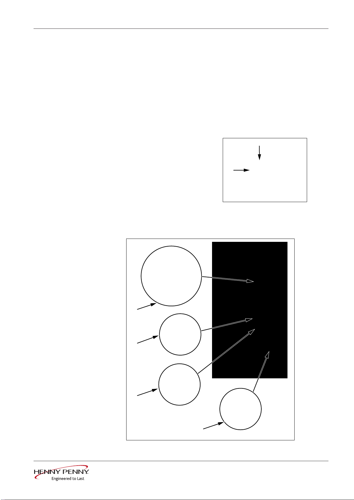
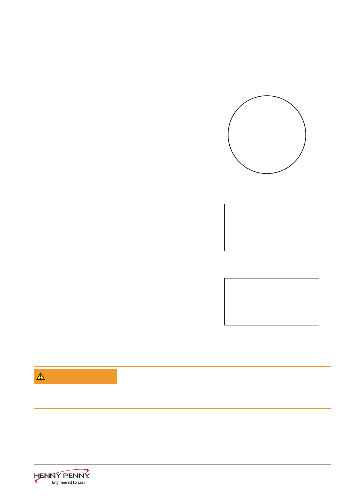
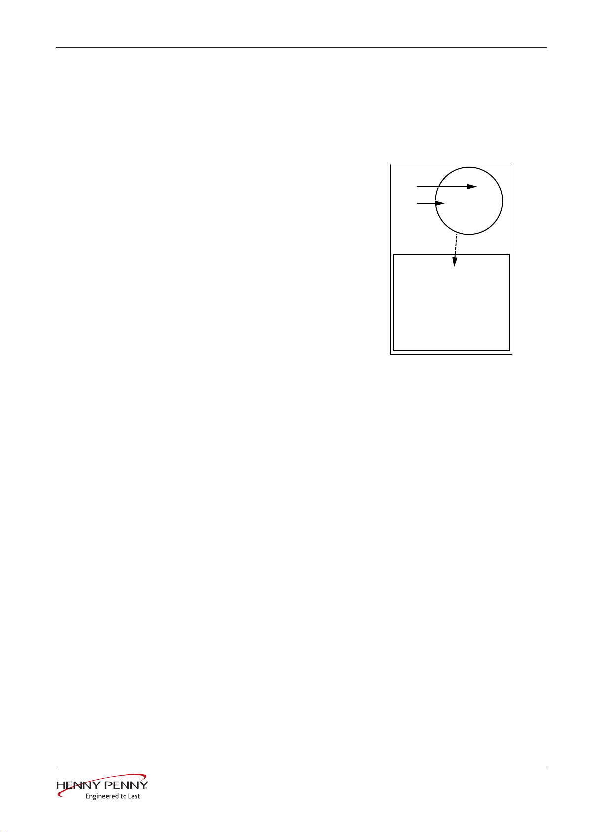
1 MagicPilot Control Panel
c
a
b
Prerequisite USB stick with current software and additional content. After replacing
the control panel or control board, a software update is absolutely
necessary. Otherwise, the unit is not functional (
update" in the service instructions)
MagicPilot Control Panel
see "Software
.
Preparations
Dismounting
• Prepare the new control
panel. Affix the included foil
(c).
• De-energize unit.
• Unlock and open control
panel.
• Disconnect all lines on the
control panel.
• Remove the SD card (a).
• Remove control panel by
lifting (b).
• Only for units with optional
radio scanner:
Dismount USB Bluetooth
receiver.
WARNING
10013865-0AMAE—
Mounting
• Mounting is done in the reverse order.
• Insert the SD card removed previously.
• Close the control panel by repeatedly pressing the left side (particularly in the
upper left). The control panel snaps in noticeably at multiple points.
• Perform the software update according to the service instructions.
• Install additional content according to service instructions.
Danger of short-circuit due to penetrating moisture
Only operate unit with foil on top.
Ensure that the control panel is completely locked.
5Assembly instructions
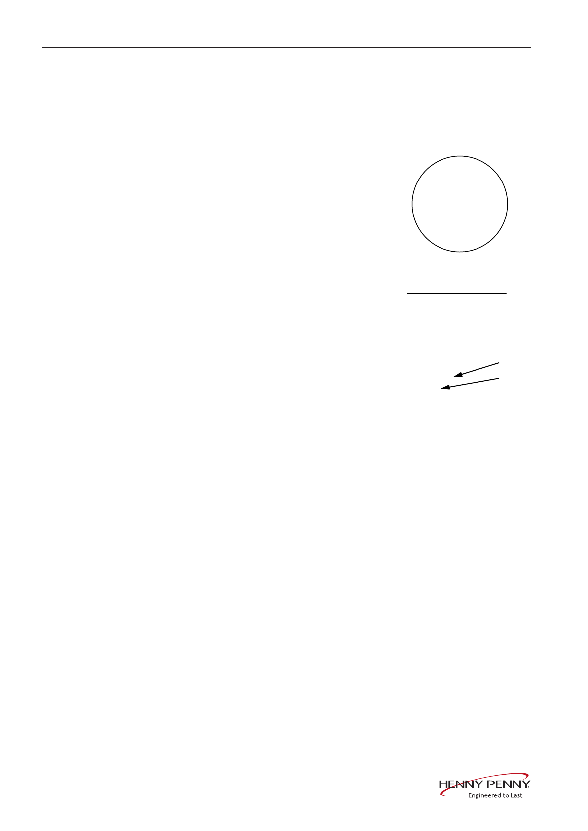
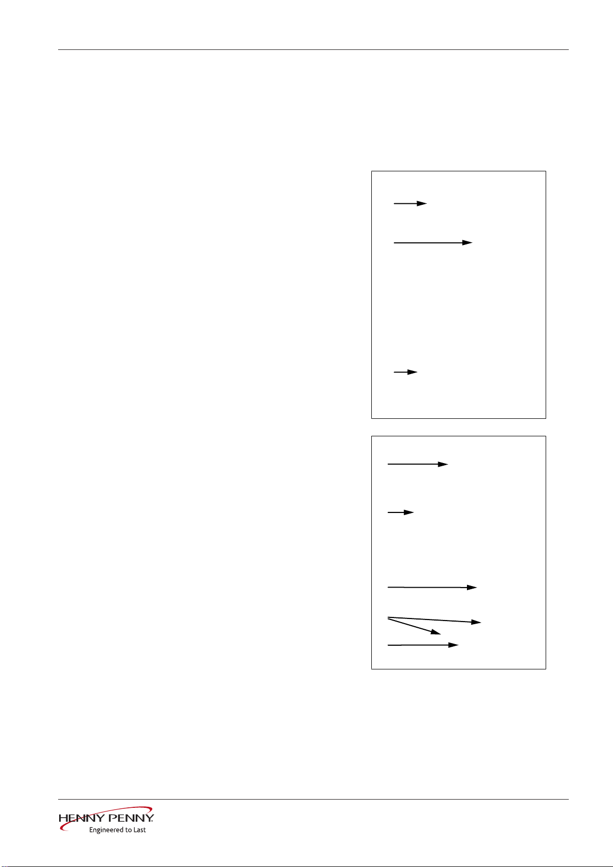
Classic control panel
g
a b c d e f
2 Classic control panel
Prerequisite USB stick with current software. After replacing the control panel or
control board, a software update is absolutely necessary. Otherwise,
the unit is not functional (
instructions)
see "Software update" in the service
.
Preparations
Dismounting
• Prepare the new control
panel. Affix the included foil
(g). Mount the included knob
or take over from existing
panel.
• De-energize unit.
• Unlock and open control
panel.
• Disconnect lines coming from
the control panel (a - e).
• Remove control panel by
lifting (f).
Mounting
WARNING
6 Assembly instructions
• Mounting is done in the reverse order.
• Close the control panel by repeatedly pressing the left side (particularly in the
upper left). The control panel snaps in noticeably at multiple points.
• Perform the software update according to the service instructions.
Danger of short-circuit due to penetrating moisture
Only operate unit with foil on top.
Ensure that the control panel is completely locked.
10013865-0AMAE—
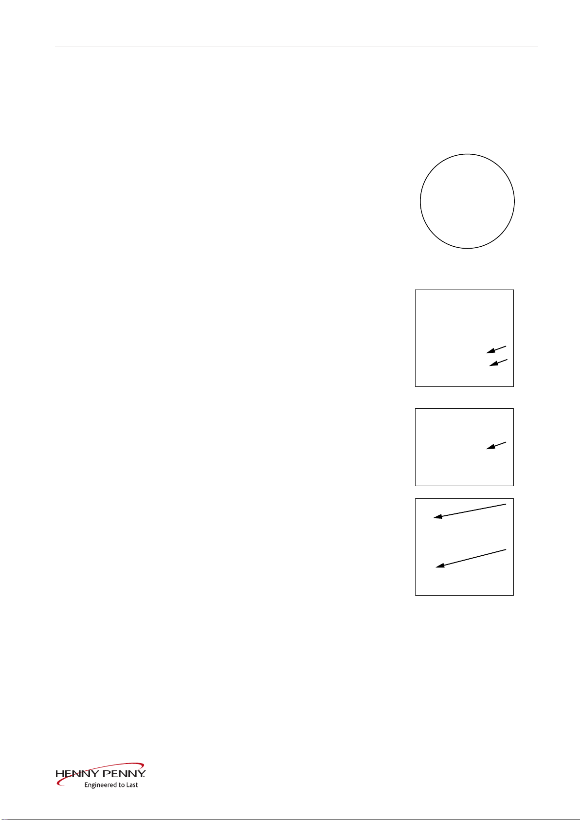
3 Control board
a
b
e
d
c
f
Prerequisite USB stick with current software. After replacing the control panel or
Control board
control board, a software update is absolutely necessary. Otherwise,
the unit is not functional (
instructions)
.
see "Software update" in the service
Preparations
Dismounting
Overview of control board
• De-energize unit.
• Unlock and open control panel.
• Insofar as possible, dismount the left side panel.
• Disconnect all connectors
from the control board. Label
sensor lines and
communication lines if
necessary.
• Dismount the control board by
unlocking the plastic clips (a,
b).
• Dismount the grounding
screw and strain relief.
• Remove the control board.
• Remove the digital key and
plug in on new control board.
10013865-0AMAE—
7Assembly instructions
Control board
c Temperature sensor connections:
X24 = B1 core temperature sensor
X25 = B2 cooking chamber sensor 1 (for 20.x upper chamber)
X26 = B3 cooking chamber sensor 2 (only for 20.x, lower chamber)
X27 = B4 vapor sensor
X28 = B5 moisture sensor
X29 = B6 sousvide sensor (option)
X29 = B7 external core temperature sensor (option)
d Digital key f Communication fan motor:
e Communication with ignition elec-
tronics (only for gas energy type):
X4 = ignition electronics A10 (for
20.x upper chamber)
X3: ignition electronics A20 (only
for 20.x, lower chamber)
X5 = motor M1 (for 20.x upper
chamber)
X6 = motor M2 (only for 20.x,
lower chamber)
8 Assembly instructions
10013865-0AMAE—
Mounting
Control board
INFORMATION
WARNING
WARNING
The unit only functions with the digital key.
Faults due to incorrect temperature sensor configuration
X25, X26 and X27 have identical connectors. Ensure correct configuration on
connection (c).
Faults due to incorrect configuration of the communication lines
for 20.x pedestal units
The lines for motors and ignition electronics have identical connectors. Ensure
correct configuration on connection (e, f).
• Mounting is done in the reverse order.
• Close the control panel by repeatedly pressing the left side (particularly in the
upper left). The control panel snaps in noticeably at multiple points.
• Perform the software update according to the service instructions.
•
Only for units with touchscreen
All data stored on the SD card is read in.
: Execute "Restore data" on the service menu.
10013865-0AMAE—
9Assembly instructions
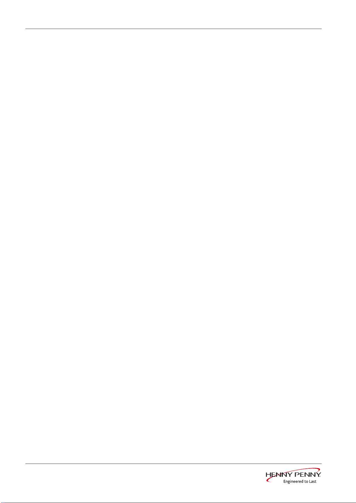
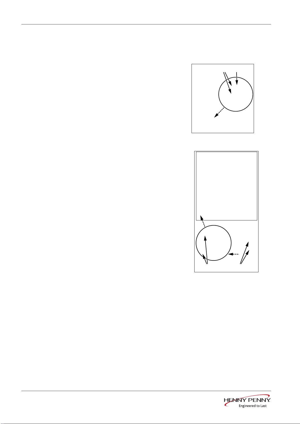
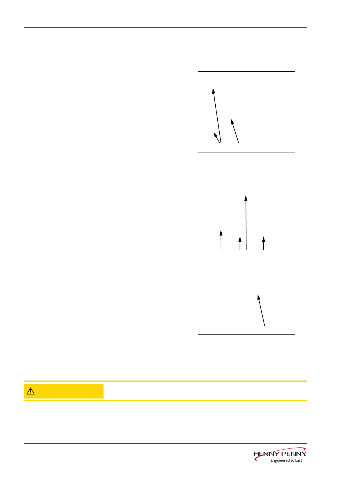
Cooking chamber sensors
a
b
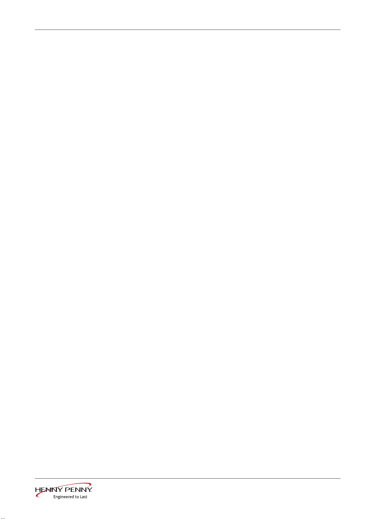
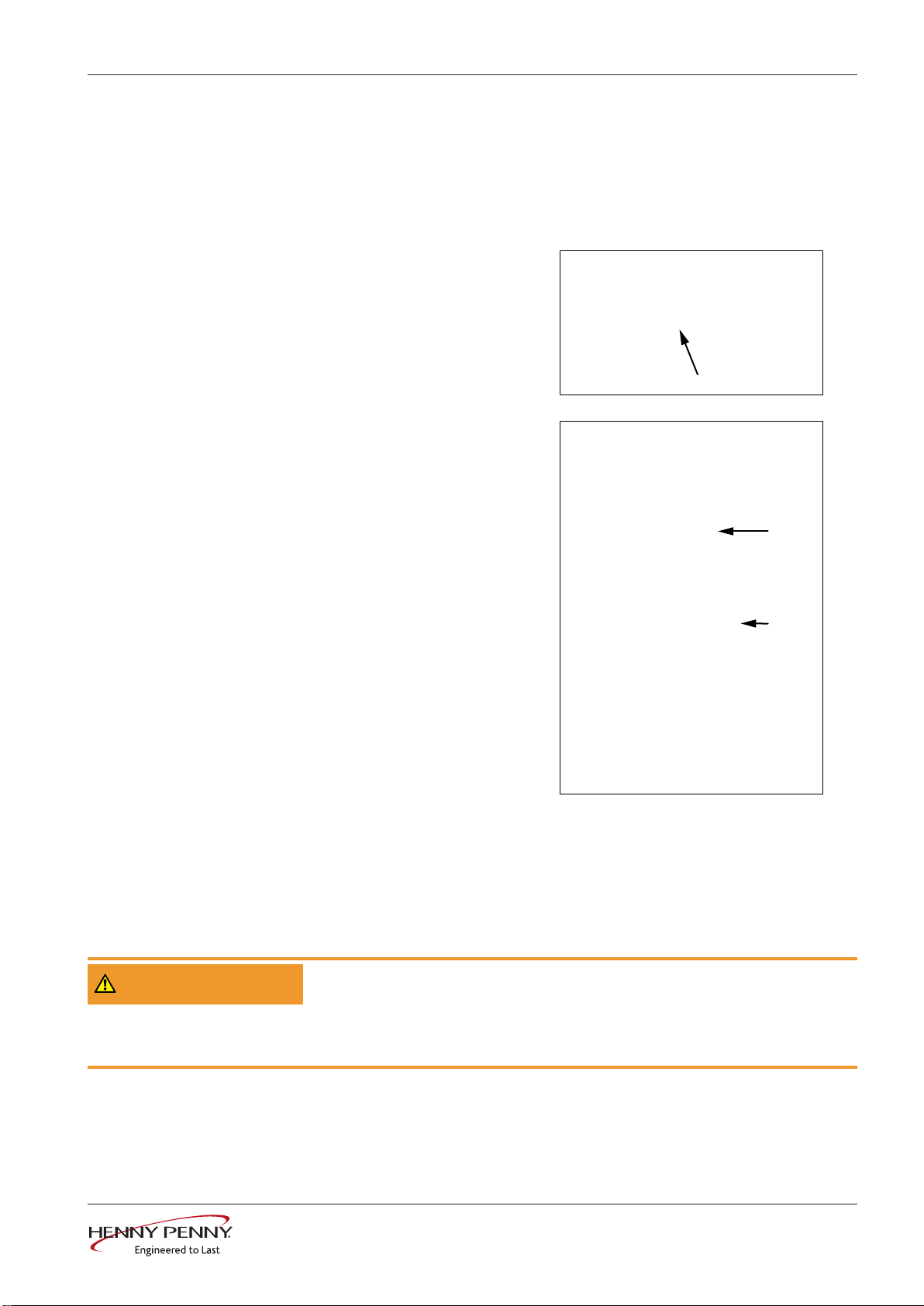
4 Cooking chamber sensors
Preparations
Dismounting / Mounting
• Disconnect unit from the power supply.
• Unlock and open control panel.
• Remove the left and right side panels.
• Remove cooking chamber sensors from
control board.
• Configuration:
X25: cooking chamber sensor B2
(for 20.x upper sensor)
• X26: cooking chamber sensor B3
(only for 20.x, lower sensor)
• Dismount strain relief.
The sensor line is laid in a hose behind the cooking chamber. The cooking chamber sensor is
mounted on the right panel of the cooking chamber.
• Loosen sensor screws and pull out cooking
chamber sensor (a, b).
• Fasten the new sensor to the existing sensor
in order to use it as strain relief. Pull sensor
through hose.
• Push cooking chamber sensor through the
Teflon sleeve and tighten the sensor screw (b,
a).
• Plug cooking chamber sensor into control
board and mount strain relief.
• Bend cooking chamber sensor slightly upward
in order to avoid drop formation on the test
prod.
Sensor connections on
Control board
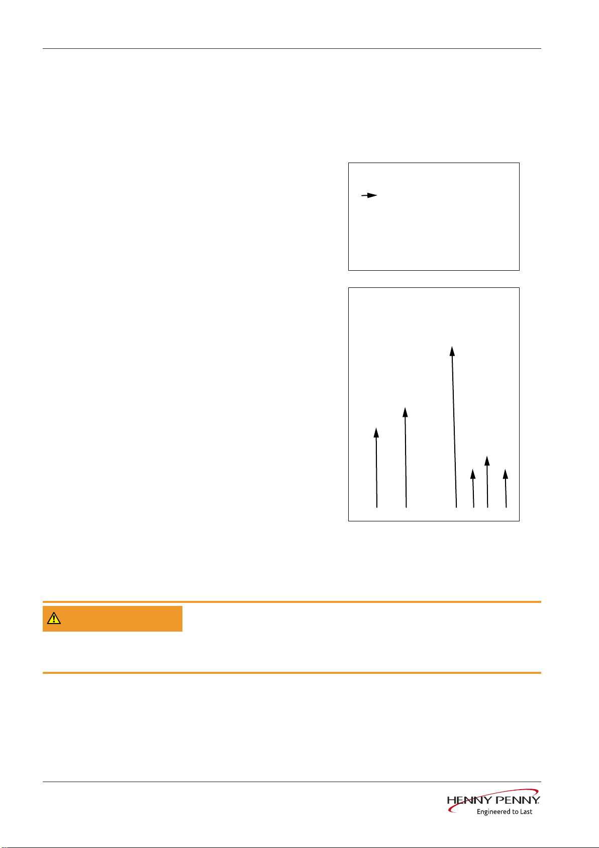
Correct sensor mounting. No bar of the protective basket may point upward.
Incorrect sensor mounting.
• Mount the side panels.
• Close the control panel by pressing.
10 Assembly instructions
10013865-0AMAE—
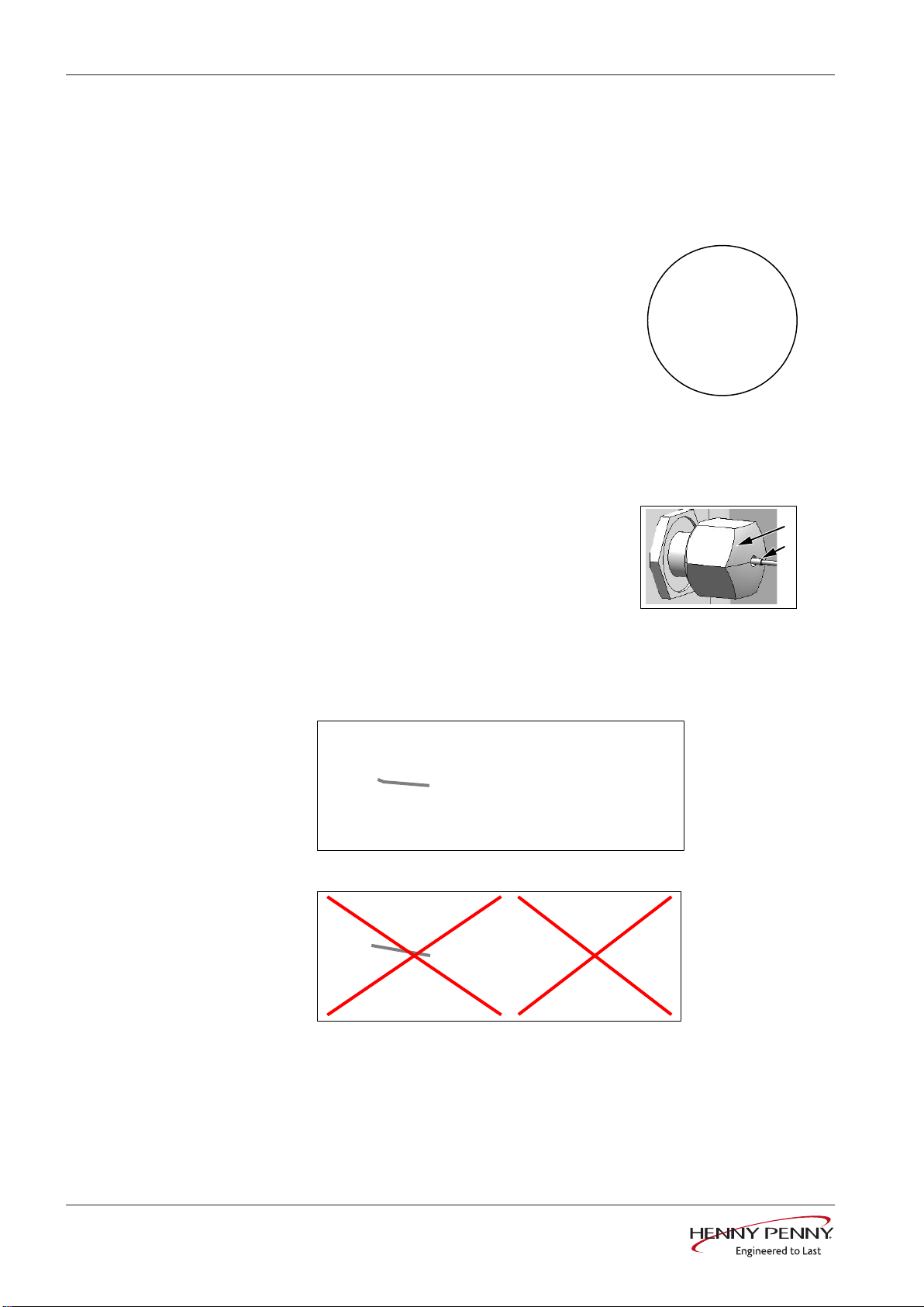
5 Core temperature sensor
Core temperature sensor
Preparations
Dismounting / Mounting
• Disconnect unit from the power supply.
• Unlock and open control panel.
• Only for 20.x pedestal units: dismount the left side panel.
• Disconnect the core temperature
sensor from the control board.
• Configuration:
X24: core temperature sensor B1
• Dismount strain relief.
Unit variants 6.x, 10.x
• Loosen sensor screw from the
front.
• Pull core temperature sensor out
of the cooking chamber side.
WARNING
Mounting
Unit variant 20.x
• Loosen sensor screw on the left
side.
• Pull core temperature sensor out
of the cooking chamber side.
• Mounting is done in the reverse order.
• Close the control panel by pressing.
• Mount side panel.
Danger of short-circuit due to penetrating moisture
Only operate unit with foil on top.
Ensure that the control panel is completely locked.
10013865-0AMAE—
11Assembly instructions
Moisture sensor
a
b
6 Moisture sensor
Preparations
Dismounting
Mounting
• Disconnect unit from the power supply.
• Unlock and open control panel.
• Remove the left side panel.
• Remove moisture sensor from the control
board.
• Configuration:
X28: moisture sensor B5
• Dismount strain relief.
The moisture sensor is in the lower area on the
supply air pipe.
• Loosen sensor screw (a).
• Pull moisture sensor out (b).
• Push moisture sensor through Teflon sleeve
(b).
• Tighten sensor screw (a).
• Plug moisture sensor into control board and
mount strain relief.
• Mount side panel.
• Close the control panel by pressing.
Sensor connections on
Control board
12 Assembly instructions
10013865-0AMAE—
7 Vapor sensor
a
b
c
d
e
Vapor sensor
Preparations
Dismounting
Units with automatic
WaveClean cleaning system
• Disconnect unit from the power supply.
• Unlock and open control panel.
• Remove the left side panel.
• Remove vapor sensor from control board.
• Configuration:
X27: vapor sensor B4
• Dismount strain relief.
Sensor connections on
Control board
The water vapor sensor is on the left side of the
siphon.
• Loosen screw connection and remove sensor
(b, a).
Units without automatic
WaveClean cleaning system
Mounting
The vapor sensor is in the drain area under the
cooking chamber.
• Remove protective cover by dismounting the
screws (c).
• Loosen screw connection and remove sensor
(e, d).
• Mounting is done in the reverse order.
• Close the control panel by pressing.
10013865-0AMAE—
13Assembly instructions
Reed contact switch
a b
a b
8 Reed contact switch
Preparations
Dismounting for units with
cooking chamber door
hooked into the right
Dismounting for units with
cooking chamber door
hooked into the left
• Disconnect unit from the power supply.
• Unlock and open control panel.
• Disconnect connector X21 from the
reed contact switch of the control
board.
• Dismount screws and remove reed
contact switch (b, a).
• Remove the right side panel.
• Dismount screws and remove
mounting plate with reed contact
switch (a).
• Loosen screws for mounting plate and
remove reed contact switch (b).
• Unplug lines from plug connector.
Mounting
• Mounting is done in the reverse order.
• Close the control panel by pressing.
14 Assembly instructions
10013865-0AMAE—
9 Pressure switch
a
b
Pressure switch
Preparations
Dismounting
Mounting
• Disconnect unit from the power supply.
• Shut off customer-supplied water supply on the soft water connection.
• Reduce water pressure in the supply line.
• Remove the left side panel.
• Unplug both connectors from the
pressure switch (b).
• Pull retainer clip out (a).
• Remove pressure switch.
• Mounting is done in the reverse order.
10013865-0AMAE—
15Assembly instructions

Steaming unit
a b a b
c d bc
10 Steaming unit
Preparations
Dismounting
• Disconnect unit from the power supply.
• Shut off customer-supplied water supply on the soft water connection.
• Reduce water pressure in the supply line.
• Remove the left side panel.
• Dismount connectors on both magnetic valves.
• Unplug connector from the pressure switch (a) (if present).
• Dismount connection nut (b).
• Dismount water supply. Dismount both screws on the unit bottom (c)
• Remove steaming unit and take over mounting plate on the new
steaming unit.
Mounting
• Mounting is done in the reverse order.
• The marking "P" must be on the bottom. The sieve (d) on the intake
side must always be present.
16 Assembly instructions
10013865-0AMAE—
Magnetic valve water vapor elimination
a
b
c
a
b
d
e
f
11 Magnetic valve water vapor elimination
Preparations
Dismounting for units with
hand shower
• Disconnect unit from the power supply.
• Block customer-supplied water supply.
• Reduce water pressure in the supply line.
• Remove the left side panel.
• Unplug connector from
magnetic valve (b).
• Loosen clamp and remove
hose (a).
• Loosen connection nut and
remove magnetic valve (c).
Dismounting for units
without hand shower
Mounting
• Unplug connector from
magnetic valve (b).
• Loosen clamp and remove
hose (a).
• Dismount water supply.
Dismount both screws on the
unit bottom (e).
• Remove magnetic valve and
mounting plate (d).
• Pull out sieve and clean if
necessary (f).
• Mounting is done in the reverse order.
• The sieve (f) on the intake side must always be present.
10013865-0AMAE—
17Assembly instructions

Solenoid
a
b
c
a
d
e
f
g
h
12 Solenoid
Preparations
Dismounting
• Disconnect unit from the power supply.
• Remove the left side panel.
• Loosen threaded cable connection (b).
• Loosen clamps (a).
• Pull silicone hose (c) upward.
• Dismount screws (d).
• Remove solenoid (e).
• Dismount solenoid mechanics (f).
Mounting
• Mounting is done in the reverse order.
• If necessary, replace seal #211080 (h).
• Glue in the solenoid mechanics with
screw locking paint.
• The solenoid height (g) must be
between 5-7 mm.
18 Assembly instructions
10013865-0AMAE—

13 Power board for motor
a
a
a
Preparations
Power board for motor
DANGER
Dismounting 6.x, 10.x
Dismounting 20.x The unit variant has two identical power boards.
Warning: electric shock! Danger of death!
When working on the power board, make sure that energized parts are ex-
posed. Work on these components during operation and up to 3 minutes after
enabling is not allows. Even if the motor is stopped and the appliance is de-en-
ergized, the connection terminals and components can conducted dangerous
voltage!
• Disconnect unit from the power supply.
• Remove the left side panel.
• Dismount screws (a).
• Remove power board with
cooling elements. The cooling
element is a component of the
assembly.
• Loosen all electrical
connections from the power
board.
Mounting
• Dismount screws of the
appropriate power board (a).
• Remove power board with
cooling elements. The cooling
element is a component of the
assembly.
• Loosen all electrical
connections from the power
board.
• Mounting is done in the reverse order.
10013865-0AMAE—
19Assembly instructions

Semiconductor relay (SSR)
a
b c
14 Semiconductor relay (SSR)
Preparations
Dismounting 6.x, 10.x
• Disconnect unit from the power supply.
• Remove the left side panel.
• Dismount screws (a).
• Remove cooling elements
with semiconductor relay
upward.
• Dismount screws from
semiconductor relay to be
replaced and remove.
• Dismount lines.
Dismounting 20.x The unit variant has four semiconductor relays. The dismounting is
identical to the unit variant 6.x, 10.x.
• b = semiconductor relay for
upper heating circuit
• c = semiconductor relay for
lower heating circuit
Mounting
• Mounting is done in the reverse order.
20 Assembly instructions
10013865-0AMAE—

15 Fan motor
a
b
c
Fan motor
Preparations
Dismounting
• Disconnect unit from the power supply.
• Remove the left side panel.
• Remove air diverter in the cooking chamber.
• Wear gloves when performing mounting work.
• Heed notes from the puller used.
• Dismount fastening screw (a).
• Remove fan impeller from the
conical motor shaft with threeleg puller or segment puller
(b).
• Gasket of the axle is loose.
For this, loosen all four
screws one turn apiece (c).
10013865-0AMAE—
21Assembly instructions

Fan motor
d
d
e
• Remove electrical
connections from the motor.
• Loosen hoses fastened on the
motor.
• Remove nuts and remove
motor (d).
• Remove shaft seal by
loosening the screws.
• Remove shaft seal (e).
Mounting
• Mounting is done in the reverse order.
• Replace shaft seal #211084.
• Mount axle seal loosely. Do not tighten screws.
• Apply special grease (temperature-resistant, food safe) on motor shaft (only
apply a thin coat, not in the area of the axle cone).
• Fasten motor with nuts (d) crosswise. Tightening torque 20 Nm.
• Fasten axle seal from the cooking chamber side. Turn motor shaft and
tighten the four screws crosswise so they are hand-tight.
• Insert the fan impeller and mount the impeller fastening screw. Tightening
torque 35 Nm.
• Make the electrical connections for the motor.
• Fasten hoses to motor again.
• Final function check.
• Mount air diverter and left side panel.
22 Assembly instructions
10013865-0AMAE—

16 Heating element
a
b
c d
Heating element
Preparations
Dismounting
• De-energize unit.
• Remove the left side panel.
• Unlock and open air diverter.
• Dismount lines from
semiconductor relay (a).
• Disconnect line from
contactor Q1, terminal 5L3
(b).
• Dismount screw from water
intake pipe in the cooking
chamber (c).
• Disconnect water intake pipe.
• Dismount all nuts from the
heating element (d).
10013865-0AMAE—
23Assembly instructions

Heating element
e
• Dismount nuts on front
retaining clip.
• Remove heating element.
Mounting
Mounting notes for screw
connections
• Mounting is done in the
reverse order.
• The seal on the flange must
be replaced.
• Use anti-seize mounting paste for the nuts on the heating element.
• Tighten the nuts of the heating element with 6 Nm.
24 Assembly instructions
10013865-0AMAE—

17 WaveClean pump
a
b c
d
e
d
17.1 Circulation pump 6.x, 10.x
WaveClean pump
Preparations
Dismounting
• Activate relay K24 via the relay test on the service menu. The drain pump
pumps the water out of the siphon.
• Disconnect unit from the power supply.
• Remove the left side panel.
• Dismount the screw from the
left protective box (a).
• Remove protective box.
• Loosen hose clamp and
remove hose from the pump
(c).
• Unplug connector (b).
• Dismount nuts and remove
pump from the siphon (d).
• Attention! Water can escape
from the siphon.
Mounting
10013865-0AMAE—
• Mounting is done in the reverse order.
• Replace the seal between siphon and pump #211131.
25Assembly instructions

WaveClean pump
a
b
c
d
e
17.2 Circulation pump 20.x
Preparations
Dismounting
• Activate relay K24 via the relay test on the service menu. The drain pump
pumps the water out of the siphon.
• Disconnect unit from the power supply.
• Remove the left side panel.
• Dismount supply air box (a).
• Dismount supply air box (b).
• Loosen hose clamp. Remove
hose from the pump (c).
Mounting
• Dismount nuts and remove
pump from the siphon.
Attention! Water can escape
from the siphon (d).
• Unplug connector.
• Seal (e).
• Mounting is done in the reverse order.
• Replace the seal between siphon and pump #211131.
26 Assembly instructions
10013865-0AMAE—

17.3 Drain pump 6.x, 10.x
a
bb
c d e
WaveClean pump
Preparations
Dismounting
• Unlock air diverter and unfold.
• Activate relay K16 via the relay test on the service menu. The siphon pump
pumps the water into the cooking chamber. Catch water with container.
• Disconnect unit from the power supply.
• Remove the left side panel.
• Dismount the screw from the
front protective box (a).
• Remove protective box.
• Dismount nuts (b).
• Attention! Water can escape
from the siphon.
• Loosen hose clamp and
remove hose from the pump
(d).
• Unplug connector (e).
Mounting
10013865-0AMAE—
• Mounting is done in the reverse order.
• Replace the seal between siphon and pump #211131.
27Assembly instructions

WaveClean pump
a
b
c
d
e
17.4 Drain pump 20.x
Preparations
Dismounting
• Unlock air diverter and unfold.
• Activate relay K16 via the relay test on the service menu. The siphon pump
pumps the water into the cooking chamber. Catch water with container.
• Disconnect unit from the power supply.
• Remove the left side panel.
• Dismount supply air box (a).
• Dismount supply air box (b).
• Loosen hose clamp and
remove hose from the pump
(c).
Mounting
• Dismount nuts and remove
pump from the siphon.
Attention! Water can escape
from the siphon (d).
• Unplug connector.
• Seal (e).
• Mounting is done in the reverse order.
• Replace the seal between siphon and pump #211131.
28 Assembly instructions
10013865-0AMAE—

18 Cooling fan
b
a
b
c
Cooling fan
Preparations
Dismounting 6.x
Dismounting 10.x
• Disconnect unit from the power supply.
• Unlock and open control
panel.
• Fold retaining clip up (b).
• Remove all electrical
connections from the fan.
• Remove fan.
• Remove the left side panel.
• Dismount screws (a).
• Remove cooling elements
with semiconductor relay
upward.
• Remove all electrical
connections from the fan.
• Fold retaining clip up (b).
• Remove fan.
Dismounting 20.x The unit variant has two identical cooling fans.
• Remove the left side panel.
• Remove all electrical
connections from the fan.
• Dismount screws (c).
• Remove fan.
Mounting
10013865-0AMAE—
• Mounting is done in the reverse order.
29Assembly instructions

Control transformer
a
b
19 Control transformer
Preparations
Dismounting
Mounting
• Disconnect unit from the power supply.
• Remove the left side panel.
• Unplug connector from
transformer.
• Bend metal tab.
• Remove transformer.
• Mounting is done in the reverse order.
• If the metal tab (a) breaks off, use replacement tab (b).
30 Assembly instructions
10013865-0AMAE—

20 Door latch
a b
c d e f
20.1 Door latch 6.x, 10.x
Door latch
Preparations
Dismounting
• Open cooking chamber door.
• Dismount screws (a).
• Remove cover (b).
• Remove sticker from door
handle.
• Dismount screw on door
handle (f).
• Remove door handle (e).
• Dismount screws from door
latch (c).
• Remove door latch (d).
10013865-0AMAE—
Mounting
• Mounting is done in the reverse order.
• Glue screws of the door latch with screw locking adhesive (c).
31Assembly instructions
Door latch
a b
c d cc
e
20.2 Door latch 20.x
Preparations
Dismounting
• Open cooking chamber door.
• Dismount screws (a).
• Remove cover (b).
• Remove metal disk (d).
• Dismount screws from door
latch (c).
• Remove door latch.
CAUTION
Mounting
• Remove sticker from door
handle.
• Dismount screw on door
handle (e).
• Remove door handle.
• Mounting is done in the reverse order.
• Glue screws of the door latch with screw locking adhesive (c).
Mount door handle first on new door latch.
32 Assembly instructions
10013865-0AMAE—

21 Cooking chamber door
a
b
a b
Cooking chamber door
Preparations
Dismounting
• Close the cooking chamber door.
• Mark position of upper door hinge. This makes it easier to set the new
cooking chamber door.
• Dismount screws (a).
• Remove door hinge (b).
• Open cooking chamber door.
• Unhook cooking chamber
door.
• Loosen screws (a).
• Remove cover (b).
• Loosen the three screws from
the door latch.
• Remove door latch together
with door handle.
Mounting
10013865-0AMAE—
• Mounting is done in the reverse order.
• Glue screws of the door latch with screw locking adhesive.
• Secure seal of the cooking chamber door. The gap between housing and
cooking chamber door is 12 mm.
33Assembly instructions

Cooking chamber light
a
22 Cooking chamber light
Preparations
Dismounting
• De-energize unit.
• Remove the right side panel.
• Dismount nuts (a).
• Remove reflector.
• Remove light bulb from
socket.
Mounting
34 Assembly instructions
• Mounting is done in the reverse order.
10013865-0AMAE—

23 Transformer glow electrode
Transformer glow electrode
Preparations
Dismounting 6.x, 10.x
• Disconnect unit from the power supply.
• Remove the left side panel.
• Unplug connector from
transformer.
• Dismount both screws.
• Remove transformer.
Dismounting 20.x The unit variant has two transformers:
• Upper transformer for glow electrode of upper burner.
Mounting
• Lower transformer for glow electrode of lower burner.
• Unplug connector from
transformer.
• Dismount both screws.
• Remove transformer.
• Mounting is done in the reverse order.
10013865-0AMAE—
35Assembly instructions

Gas solenoid valve
a
c f e b d
24 Gas solenoid valve
Preparations
Dismounting
• De-energize unit.
• Shut off the gas supply.
• Remove the left side panel.
• Loosen screws and remove
cover (a).
• Remove electrical
connections.
• Remove ignition electronics
from the magnetic valve.
• Remove supply pipe from
Venturi pipe (b).
• Remove screws from Venturi
pipe (c).
• Remove magnetic valve.
• Dismount gas hose (d).
• Remove gas orifice with seal
(e, f).
Mounting
Mounting note for screw
connections
WARNING
WARNING
• Mounting is done in the reverse order.
• Screws for gas hose (d):
- Glue in with screw locking (e.g. Loctite 586)
- Tighten with tightening torque 3 Nm.
• Screws for Venturi pipe (c):
- Mount with anti-seize paste
- Tighten with tightening torque 3 Nm.
Risk of asphyxiation and explosion from damaged seals
• Check seals for damage.
• Replace damaged seals.
Risk of explosion and fire from leaking, gas-conducting parts
• Heed tightening torques for the screw connections.
• Check the gas connection line and all gas-conducting parts for leaks at the
operating pressure.
36 Assembly instructions
10013865-0AMAE—

Gas solenoid valve
NOTICE
Risk of poisoning from exhaust gases
• CO22 calibration required.
ð Perform CO22 calibration according to installation instructions/service
instructions.
10013865-0AMAE—
37Assembly instructions

Gas fan
a
b
c
d
e
25 Gas fan
Preparations
Dismounting
• De-energize unit.
• Shut off the gas supply.
• Remove the left side panel.
• If necessary, dismount the exhaust pipe in the unit.
• Dismount the gas solenoid valve (see „24 Gas solenoid valve‟, Page 36).
• Loosen screws and remove
the Venturi pipe (a).
• Unplug connector from gas
fan (b).
• Remove screws from gas fan
(d).
• Loosen screws of gas fan (c).
• Remove gas fan toward the
bottom.
Mounting
Mounting note for screw
connections
• Mounting is done in the
reverse order.
• Both seals must be replaced
(e).
For all screws, use anti-seize mounting paste.
Screws for Venturi pipe (a):
- Tighten with tightening torque 3 Nm.
Screws for gas fan (c, d):
- Tighten with tightening torque 5 Nm.
10013865-0AMAE—
38 Assembly instructions

Gas fan
WARNING
WARNING
Risk of asphyxiation and explosion from damaged seals
• Check seals for damage.
• Replace damaged seals.
Risk of explosion and fire from leaking, gas-conducting parts
• Heed tightening torques for the screw connections.
• Check the gas connection line and all gas-conducting parts for leaks at the
operating pressure.
10013865-0AMAE—
39Assembly instructions

Gas burner
a
a
a
b
26 Gas burner
Preparations
Dismounting
• De-energize unit.
• Shut off the gas supply.
• Remove the left side panel.
• If necessary, dismount the exhaust pipe in the unit.
• Dismount the gas solenoid valve (see „24 Gas solenoid valve‟, Page 36).
• Dismount the gas fan (see „25 Gas fan‟, Page 38).
• Dismount nuts and Venturi
pipe (a).
• Unplug connectors of the
glow electrodes from the
transformer.
• Remove gas burner.
Mounting
Mounting note for screw
connections
WARNING
• Mounting is done in the
reverse order.
• Both seals must be replaced
(b).
For all nuts, use anti-seize mounting paste.
Nuts for gas burner (a):
- Tighten with tightening torque 6 Nm.
Risk of asphyxiation and explosion from damaged seals
• Check seals for damage.
40 Assembly instructions
10013865-0AMAE—

• Replace damaged seals.
Gas burner
WARNING
Risk of explosion and fire from leaking, gas-conducting parts
• Heed tightening torques for the screw connections.
• Check the gas connection line and all gas-conducting parts for leaks at the
operating pressure.
10013865-0AMAE—
41Assembly instructions

Glow and ionization electrodes
a
b
27 Glow and ionization electrodes
Preparations
Dismounting
• De-energize unit.
• Shut off the gas supply.
• Remove the left side panel.
• Dismount the gas solenoid valve (see „24 Gas solenoid valve‟, Page 36).
• Dismount the gas fan (see „25 Gas fan‟, Page 38).
• Dismount the gas burner (see „26 Gas burner‟, Page 40).
• Loosen threaded cable
connection and pull out lines.
Glow electrode
• Dismount nuts and glow
electrode (a).
Ionization electrode
• Dismount nuts and remove
ionization electrode (b).
Mounting
42 Assembly instructions
• Mounting is done in the reverse order.
• The cable feedthrough must be replaced.
10013865-0AMAE—

Glow and ionization electrodes
Mounting note for screw
connections
WARNING
WARNING
NOTICE
For all nuts, use anti-seize mounting paste.
Risk of asphyxiation and explosion from damaged seals
• Check seals for damage.
• Replace damaged seals.
Risk of explosion and fire from leaking, gas-conducting parts
• Heed tightening torques for the screw connections.
• Check the gas connection line and all gas-conducting parts for leaks at the
operating pressure.
Risk of poisoning from exhaust gases
• CO22 calibration required.
ð Perform CO22 calibration according to installation instructions/service
instructions.
10013865-0AMAE—
43Assembly instructions

Gas heat exchanger
a b b
c
28 Gas heat exchanger
Preparations
Dismounting
• De-energize unit.
• Shut off the gas supply.
• Remove the left side panel.
• Dismount the gas solenoid valve (see „24 Gas solenoid valve‟, Page 36).
• Dismount the gas fan (see „25 Gas fan‟, Page 38).
• Dismount the gas burner (see „26 Gas burner‟, Page 40).
• Remove insulation from
exhausts pipe (a).
• Dismount nuts (b).
• Dismount nuts. The positions
can vary (c).
• Remove retainer plate.
• Remove heat exchanger.
Mounting
Mounting note for screw
connections
WARNING
• Mounting is done in the reverse order.
• All seals must be replaced.
For all nuts, use anti-seize mounting paste.
Tighten all nuts of the gas heat exchanger with 6 Nm.
Risk of asphyxiation and explosion from damaged seals
• Check seals for damage.
• Replace damaged seals.
44 Assembly instructions
10013865-0AMAE—

Gas heat exchanger
WARNING
NOTICE
Risk of explosion and fire from leaking, gas-conducting parts
• Heed tightening torques for the screw connections.
• Check the gas connection line and all gas-conducting parts for leaks at the
operating pressure.
Risk of poisoning from exhaust gases
• CO22 calibration required.
ð Perform CO22 calibration according to installation instructions/service
instructions.
10013865-0AMAE—
45Assembly instructions

Gas burner pipe
b b ca
d
29 Gas burner pipe
Preparations
Dismounting
Mounting
• De-energize unit.
• Shut off the gas supply.
• Remove the left side panel.
• Dismount the gas solenoid valve (see „24 Gas solenoid valve‟, Page 36).
• Dismount the gas fan (see „25 Gas fan‟, Page 38).
• Dismount the gas burner (see „26 Gas burner‟, Page 40).
• Dismount screws (b).
• Remove burner pipe (c).
• Mounting is done in the
reverse order.
• The seal on the burner pipe
must be replaced (a).
• Make sure that there are no
metal hairs in the area of the
ionization electrode (d).
Mounting note for screw
connections
WARNING
WARNING
NOTICE
For all screws, use anti-seize mounting paste.
Risk of asphyxiation and explosion from damaged seals
• Check seals for damage.
• Replace damaged seals.
Risk of explosion and fire from leaking, gas-conducting parts
• Heed tightening torques for the screw connections.
• Check the gas connection line and all gas-conducting parts for leaks at the
operating pressure.
Risk of poisoning from exhaust gases
• CO22 calibration required.
46 Assembly instructions
10013865-0AMAE—

Gas burner pipe
ð Perform CO22 calibration according to installation instructions/service
instructions.
10013865-0AMAE—
47Assembly instructions

Gas burner pipe
48 Assembly instructions
10013865-0AMAE—


*10013865-0AMAE—*
Copyright
All rights to text, graphics and pictures
in this documentation are held by MKN
Maschinenfabrik Kurt Neubauer
GmbH & Co. KG. Distribution or
duplication is exclusively permissible
subject to a written consent of MKN.
Copyright by MKN Maschinenfabrik
Kurt Neubauer GmbH & Co. KG
Manufacturer
Copyright by MKN Maschinenfabrik
Kurt Neubauer GmbH & Co. KG
Halberstaedter Strasse 2a
D-38300 Wolfenbuettel
Telephone 0 53 31 / 89-0
Telefax 0 53 31 / 89-280
 Loading...