

Page 1
Page 2
Henny Penny Model BCC/BCR-140, BCC/BCR-175, BFR/BCR-350
Henny Penny Blast Chiller/Freezer
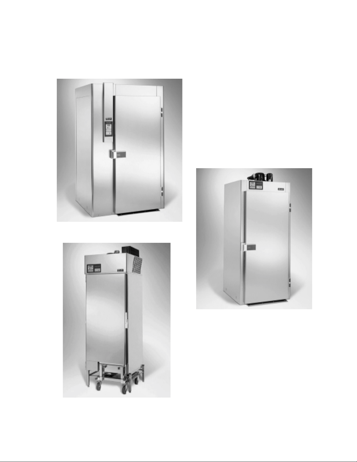
BFR/BCR-350
BCC/BCR-175
BCC/BCR-140
Page 3

Henny Penny Model BCC/BCR-140, BCC/BCR-175, BFR/BCR-350
LIMITED WARRANTY FOR HENNY PENNY APPLIANCES
Subject to the following conditions, Henny Penny Corporation makes the following limited warranties to the
original purchaser only for Henny Penny appliances and replacement parts:
NEW EQUIPMENT: Any part of a new appliance, except lamps and fuses, which proves to be defective
in material or workmanship within two (2) years from date of original installation, will be repaired or replaced
without charge F.O.B. factory, Eaton, Ohio, or F.O.B. authorized distributor. To validate this warranty, the
registration card for the appliance must be mailed to Henny Penny within ten (10) days after installation.
REPLACEMENT PARTS: Any appliance replacement part, except lamps and fuses, which proves to be
defective in material or workmanship within ninety (90) days from date of original installation will be repaired
or replaced without charge F.O.B. factory, Eaton, Ohio, or F.O.B. authorized distributor.
The warranty for new equipment and replacement parts covers only the repair or replacement of the defective
part and does not include any labor charges for the removal and installation of any parts, travel or other expenses
incidental to the repair or replacement of a part.
EXTENDED FRYPOT WARRANTY: Henny Penny will replace any frypot that fails due to manufacturing or
workmanship issues for a period of up to seven (7) years from date of manufacture. This warranty shall not cover
any frypot that fails due to any misuse or abuse, such as heating of the frypot without shortening.
0 TO 3 YEARS: During this time, any frypot that fails due to manufacturing or workmanship issues will be replaced at no charge for parts, labor, or freight. Henny Penny will either install a new
frypot at no cost or provide a new or reconditioned replacement fryer at no cost.
3 TO 7 YEARS: During this time, any frypot that fails due to manufacturing or workmanship issues will be replaced at no charge for the frypot only. Any freight charges and labor costs to install
the new frypot as well as the cost of any other parts replaced, such as insulation, thermal sensors,
high limits, fittings, and hardware, will be the responsibility of the owner.
Any claim must be represented to either Henny Penny or the distributor from whom the appliance was purchased. No allowance will be granted for repairs made by anyone else without Henny Penny’s written consent. If
damage occurs during shipping, notify the sender at once so that a claim may be filed.
THE ABOVE LIMITED WARRANTY SETS FORTH THE SOLE REMEDY AGAINST HENNY PENNY
FOR ANY BREACH OF WARRANTY OR OTHER TERM. BUYER AGREES THAT NO OTHER REMEDY
(INCLUDING CLAIMS FOR ANY INCIDENTAL OR CONSQUENTIAL DAMAGES) SHALL BE AVAILABLE.
The above limited warranty does not apply (a) to damage resulting from accident, alteration, misuse, or abuse;
(b) if the equipment’s serial number is removed or defaced; or (c) for lamps and fuses. THE ABOVE LIMITED
WARRANTY IS EXPRESSLY IN LIEU OF ALL OTHER WARRANTIES, EXPRESS OR IMPLIED, INCLUDING MERCHANTABILITY AND FITNESS, AND ALL OTHER WARRANTIES ARE EXCLUDED. HENNY
PENNY NEITHER ASSUMES NOR AUTHORIZES ANY PERSON TO ASSUME FOR IT ANY OTHER OBLIGATION OR LIABILITY.
FM01-781
Page 4

Henny Penny Model BCC/BCR-140, BCC/BCR-175, BFR/BCR-350
TABLE OF CONTENTS
Section Page
Section 1. INTRODUCTION ................................................................................................................... 1-1
1-1. Henny Penny Blast Chiller ........................................................................................... 1-1
1-2. Features ....................................................................................................................... 1-1
1-3. Proper Care ................................................................................................................. 1-1
1-4. Assistance .................................................................................................................... 1-1
1-5. Safety ........................................................................................................................... 1-2
Section 2. INSTALLATION ...................................................................................................................... 2-1
2-1. Introduction .................................................................................................................. 2-1
2-2. Unpacking .................................................................................................................... 2-1
2-3. Electrical ...................................................................................................................... 2-2
2-4. Location ....................................................................................................................... 2-3
2-5. Refrigerant Information ............................................................................................... 2-4
Section 3. OPERATION............................................................................................................................ 3-1
3-1. Introduction .................................................................................................................. 3-1
3-2. Operating Controls ....................................................................................................... 3-1
3-3. Basic Operation ........................................................................................................... 3-4
3-4. De-Icing ....................................................................................................................... 3-7
3-5. Cleaning ....................................................................................................................... 3-8
3-6. Seasonal or Prolonged Shutdown ................................................................................. 3-9
3-7. Programming ................................................................................................................ 3-10
Section 4. TROUBLESHOOTING ........................................................................................................... 4-1
4-1. Introduction .................................................................................................................. 4-1
4-2. Troubleshooting ............................................................................................................ 4-1
Section 5. WIRING DIAGRAMS AND PARTS INFORMATION ........................................................ 5-1
Wiring Diagram - BCC-140/175 .................................................................................. 5-1
Wiring Diagram - BCR-140/175 .................................................................................. 5-2
Wiring Diagram - BCR-350 ......................................................................................... 5-3
Parts List ...................................................................................................................... 5-4
100 i
Page 5

Henny Penny Model BCC/BCR-140, BCC/BCR-175, BFR/BCR-350
SECTION 1. INTRODUCTION
1-1. BLAST CHILLER/ The Henny Penny Blast Chiller are designed to carry out fast
refrigeration of food products. The units are electronically controlled for easy use and for consistent operation. The
BCC/BCR-140, will chill up to 140 lbs (65 kg) of product, the
BCC/BCR-175 will chill up to 175 lbs (80 kg), and the BCR-350
will chill up to 350 lbs (160 kg) of product. The BFR-350 chills
and freezes up to 350 lbs. (160 kg) of product.
1-2. FEATURES • Interior and Exterior made of 304 Stainless Steel
• Electronic Controls with Self Diagnostics
• Manual De-icing of the Interior by Electrical Heater
• Multi-Sensored Frigiprobe food probe
• Easily Maintained
• The BCC-140 and BCC-175 have water cooled
condensing units
• The BCR-140, BCR-175, and BCR-350 are shipped
without condensing units
• HACCP Printer capabilities
• The BCC/BCR-140 and 175 can use the combi, MOR-20
• The BFR and BCR-350 can use the combi, MOR-40
1-3. PROPER CARE As in any unit of food service equipment, the Blast Chiller does
require care and maintenance. Suggestions for the proper care and
maintenance are contained in this manual.
The conscientious use of the recommended procedures,
coupled with regular maintenance, will result in few repairs to
the equipment. When such repairs are required, they may be
accomplished by following the repair steps contained in this
manual.
1-4. ASSISTANCE Should you require outside assistance, just call your local
independent distributor maintained by Henny Penny Corporation.
In addition, feel free to contact our corporate headquarters in
Eaton, Ohio. Dial 800-417-8405 toll free, or 937-417-8405.
201 1-1
Page 6

Henny Penny Model BCC/BCR-140, BCC/BCR-175, BFR/BCR-350
1-5. SAFETY The Henny Penny Blast Chiller has may safety features incorpo-
rated. However, the only way to ensure a safe operation is to fully
understand the proper installation, operation, and maintenance
procedures. The instructions in this manual have been prepared to
aid you in learning the proper procedures. Where information is of
particular importance or safety related, the words WARNING,
CAUTION, and NOTE are used. Their usage is described below.
The word WARNING is used to alert you to a procedure,
that if not performed properly, might cause personal injury,
such as burns and/or loss of sight, and damage to the unit.
The word CAUTION is used to alert you to a procedure
that, if not performed properly, may damage the unit, or
product.
NOTE
The word NOTE is used to highlight especially important
information.
1-2 100
Page 7

Henny Penny Model BCC/BCR-140, BCC/BCR-175, BFR/BCR-350
SECTION 2. INSTALLATION
2-1. INTRODUCTION This section provides the installation for the Henny Penny
Blast Chiller.
NOTE
Installation of this unit should be performed only by a
qualified service technician.
Do not puncture the skin of the Blast Chiller with drills or
screws, as component damage or electrical shock could
result. Also, if the unit is shipped with a compressor, Do Not
lay the unit on its side. If the unit has been on its side, the unit
must be in an upright position for at least an hour before
power is applied to the unit. Check all components for signs
of being loose or damaged, and make sure the system has
refrigerant. Failure to follow these instructions may cause
damage to the components.
2-2. UNPACKING The Henny Penny Blast Chiller has been tested, inspected, and
expertly packed to insure arrival at its destination in the best pos
sible condition. The cabinet rests on a wooden skid and is then
packed inside a wooden box with sufficient padding to withstand
normal shipping treatment.
NOTE
Any shipping damage should be noted in the presence of
the delivery agent and signed prior to his or her departure.
To remove the Henny Penny Blast Chiller from the box, you
should:
1. Carefully cut banding straps.
2. Remove box from around unit.
3. Lift the unit off the skid.
The BCC/BCR-140 and BCC/BCR-175 weighs between
400 (181 kg) and 550 lbs (249 kg), and the BFR and
BCR-350 weigh approximately 770 lbs (350 kg). Take care
when lifting units to prevent personnal injury.
201 2-1
Page 8

Henny Penny Model BCC/BCR-140, BCC/BCR-175, BFR/BCR-350
2-2. UNPACKING 4. Open door and remove packing from the inside of the unit.
(Continued)
5. Peel off any protective covering from the exterior of the
cabinet.
6. Your Blast Chiller is now ready for operation.
If the blast chiller has been laid on its side, the unit must be
sitting upright for at least an hour before applying power to
the unit. Check all components for signs of being loose or
damaged, and make sure the system has refrigerant. Failure
to follow these instructions may causedamage to the
components. Failure to follow these instructions could cause
damage to the compressor.
NOTE
Be certain to save any literature that is packed inside the
cabinet, or separate boxes.
2-3. ELECTRICAL BCC-140 • 200 V, 50-60 Hz, 3 phase
• 208-240 V, 60 Hz, 3 phase
• 230 V, 50 Hz., 1 phase
BCC-175 • 200 V, 50-60 Hz, 3 phase
• 208-240 V, 60 Hz, 3 phase
• 400 V, 50 Hz., 3N phase
BCR-140 and 175 • 208-240 V, 60 Hz, single phase
• 230 V, 50 Hz, single phase
• 200 V, 50-60 Hz., single phase
BFR and BCR-350 • 200 V, 50-60 Hz, 3 phase
• 208-240 V, 60 Hz, 3 phase
• 400 V, 50 Hz., 3N phase
The data plate, located inside of the unit, will specify the correct
electrical supply. The unit requires a grounded receptacle with a
separate electrical line protected by a fuse or circuit breaker of the
proper rating.
The cabinet must be adequately and safely grounded
according to local electrical codes to prevent the possibility of electrical shock.
2-2 201
Page 9

Henny Penny Model BCC/BCR-140, BCC/BCR-175, BFR/BCR-350
2-3. ELECTRICAL Refer to the table below for electrical ratings for both models.
(Continued) Model No. Volts Watts Amps Freq. Phase
BCC-140 200 4700 18 50/60 3
208-240 4700 18 60 3
230 4700 20 50 1
BCC-175 200 5800 20 50/60 3
208-240 5800 20 60 3
400 5800 9 50 3N
BCR-140 208-240 2400 12 60 1
230 2400 10 50 1
200 2400 12 50-60 1
BCR-175 200 2400 12 50/60 1
208-240 2400 12 60 1
230 2400 12 50 1
BFR & 200 4100 15 50/60 3
BCR-350 208-240 4100 15 60 3
400 4100 10 50 3N
2-4. LOCATION The Blast Chillers should be placed in an area where the doors can
be opened, for loading and unloading, without interruption. For
proper operation, the cabinet must be level.
For maximum efficiency, if the air temperature of the premises
is more than 100° F (38° C), the room should have adequate
ventilation, taking into account for the heat emitted by the unit.
Clearances should be as follows:
BCC/BCR-140 Top ........... 16 in. (400 mm) for air circulation
Left Side ... 4 in. (100 mm) for air circulation
Right Side . 8 in. (200 mm) for air circulation
Back ......... 4 in (100 mm) for air circulation
Front ........ 26 3/8 in (668 mm) for door swing
BCC/BCR-175 Top ........... 16 in. (400 mm) for air circulation
Sides ........ 3 in. (70 mm) for air circulation
Front ........ 33 3/8 in. (847 mm) for door swing
BFR & Top........... 16 in. (400 mm) for air circulation
BCR-350 Sides ........ 3 in. (70 mm) for air circulation
Pass Thru- Front and Back ... 38 1/8 in (970 mm) for door swing
Solid Back-Front ................... 38 1/8 in. (970 mm) for door swing
Back ................... 4 in. (100 mm) for air circulation
201 2-3
Page 10

Henny Penny Model BCC/BCR-140, BCC/BCR-175, BFR/BCR-350
2-5. REFRIGERANT
INFORMATION Design Pressure
Refrigerant Type Amount of Refrig. High Low
BCC-140 R404A 6 lbs. (2.7 kg) 406 psig 102psig
(28 bar) (7 bar)
BCC-175 R404A 5.5 lbs. (2.4 kg) 406 psig 102 psig
(28 bar) (7 bar)
2-6. REFRIGERATION BCC/BCR-140
CAPACITIES -4o F (-20o C) at 6,800 BTU/hr (2.0 kw)
32o F (0o C) at 16,000 BTU/hr (4.7 kw)
BCC/BCR-175
-4o F (-20o C) at 11,300 BTU/hr (3.3 kw)
32o F (0o C) at 38,800 BTU/hr (9.0 kw)
BCR-350
-4o F (-20o C) at 25,000 BTU/hr (7.3 kw)
32o F (0o C) at 58,000 BTU/hr (17.0 kw)
BFR-350
-4o F (-20o C) at 81,900 BTU/hr (24.0 kw)
-40o F (-40o C) at 35,500 BTU/hr (10.4 kw)
2-4 201
Page 11

Henny Penny Model BCC/BCR-140, BCC/BCR-175, BFR/BCR-350
SECTION 3. OPERATION
3-1. INTRODUCTION This section provides operating procedures for the Blast Chiller.
Sections 1, 2, and 3 should be read, and all instructions should be
followed before operating the cabinet.
This section contains an explanation of all controls and components and information on operating procedures and daily
maintenance.
If the blast chillers (that have compressors shipped with them)
have been laid on its side, the unit must be sitting upright for at
least an hour before applying power to the unit. Check all
components for signs of being loose or damaged, and make
sure the system has refrigerant. Failure to follow these
instructions may cause damage to the components. Failure to
follow these instructions could cause damage to the compres
sor.
3-2. OPERATING CONTROLS Pages 3-1 to 3-4 identifies and describes the function of all the
operating controls.
Fig. Item Description Function
No. No.
3-1 1 On/Off Button The On/Off button, when pressed, is a button on the
control panel that starts a chilling cycle. It also must be
pressed before any changes to the controls can be made,
and to start and stop the De-ice cycle.
3-1 2 Digital Display The Digital Display shows the temperatures, the time
(in a timing cycle), and the information in the technical
mode.
3-1 3 Up and Down The Up and Down Arrows are used when changing
Arrows times or settings.
3- 1 4 Alarm Button The Alarm button is used to stop the optional alarm buzzer
and to enter the technical mode.
3-1 5 Temp Button The Temp button is used to select either the chilling
mode.
3-1 6 De-ice Button The De-ice button is used to remove ice that may have
formed on the evaporator during a chilling cycle.
3-1 100
Page 12

Henny Penny Model BCC/BCR-140, BCC/BCR-175, BFR/BCR-350
3-2. OPERATING CONTROLS
(Continued)
Fig. Item Description Function
No. No.
3-1 7 Select Button The Select button is used to choose between a timing
cycle or a cycle using the food probe.
3-1 8 Fan LED The Fan LED is a green light which illuminates when
the fan is running.
3-1 9 Compressor LED The Compressor LED is a green light which illuminates
when the compressor is running.
3-1 10 End-of-Cycle LED The End-of-Cycle LED is a green light which illumi-
nates at the end of a timing cycle, or food probe cycle.
3-1 11 Alarm LED The Alarm LED is a red light which illuminates when
the unit senses a fault in the system. (Ex: AL 1, AL 2,
etc.).
3-1 12 Chill LED The Chill LED is a green light which illuminates when
the chilling mode is selected.
3-1 13 Freeze LED The Freeze LED is a green light which illuminates
(Only applicable when the freezing mode is selected.
on BFR units)
3-1 14 De-ice LED The De-ice LED is a green light which illuminates
when the de-ice button is pressed.
3-1 15 Timer LED The Timer LED is a green light which illuminates when
the timing cycle is selected.
3-1 16 Frigiprobe LED The Frigiprobe LED is a green light which illuminates
when the food probe mode is selected.
201 3-2
Page 13

Henny Penny Model BCC/BCR-140, BCC/BCR-175, BFR/BCR-350
3-3 100
Page 14

Henny Penny Model BCC/BCR-140, BCC/BCR-175, BFR/BCR-350
3-3. BASIC OPERATION The Henny Penny Blast Chillers can chill food products with a
core temperature of 149ºF (65ºC), down to 40ºF (4ºC) within 4
hours (room ambiant temperature may impact time it takes
to reach the desired temperature). But, for the above statements
to be accurate, the following conditions must be met:
a. The food product must not be thicker than 1¾ to 2 inches
(40 to 50 mm.)
b. Meats should be placed directly onto the racks, but prod-
ucts in pans should be covered if possible. The steam from
the product can form ice on the evaporator, which will
increase the chilling or freezing time.
c. A minimum clearance of 1 inch (25 mm) between pans.
d. The best dishes or pans to use are stainless steel or alumi-
num. Do not use polycarbonate (plastic) pans. The polycarbonate acts as an insulator around the food product and
makes it hard to chill.
e. Do not exceed the product weight capacity specified by the
particular model of blast chiller. The BCC/BCR-140 has a 140
lbs.(65 kg) capacity, the BCC/BCR-175 has a 175 lb. (80 kg)
capacity, and the BCR-350 has a 350 lb. (160 kg.) capacity.
Start-up
1. Load all the product at one time, so the door does not need
to be opened while in operation.
2. If using the food probe, place probe into product that is
located on the left side, middle of the unit.
3. Press the ON/OFF button to turn unit on. The fan and
compressor LEDs should come on after 25 seconds.
4. Press the Temp button to select the chilling mode. (Chill mode
or freeze mode can be selected on BFR units).
NOTE
The chilling LEDs, and the timing or food probe LEDs, will stay
on with the power switch turned to the OFF position.
201 3-4
Page 15

Henny Penny Model BCC/BCR-140, BCC/BCR-175, BFR/BCR-350
3-3. BASIC OPERATION 5. Press the Select button to choose the food probe mode or
(Continued)
the timing mode. With the Frigiprobe mode selected, the
digital display will alternately show the core temperature of
the product, and the elapsed time of the cycle. If the timing
mode is selected, the digital display will alternately show
the air temperature and the time (hours and minutes) remaining in the cycle.
NOTE
The buzzer will sound 1 minute after the food probe mode is
selected, unless the temperature is above 140ºF(60ºC). Then
the buzzer will sound when 140ºF (60ºC) is reached.
6. Set the time in the timing cycle, if necessary, using the Up
and Down buttons. The time is affected by the thickness of
the food product, weight, food loading temperature, and
food’s packaging. The buzzer will sound 1 minute into the
timing cycle.
NOTE
Avoid opening the door once the cycle has started. This
will lengthen the time it takes to reach the desired temperature.
7. At the end of the cycle (40ºF (4ºC) in the food probe mode)
the buzzer will sound and the unit will automatically start
the hold cycle. The buzzer will sound for 30 seconds, or
press the Alarm button to stop it. In the hold cycle, the
product will be held at 37ºF (3ºC) in the chilling mode.
8. The product can remain in the unit for up to 12 hours, or
can be removed from the unit and placed in a cold storage
case.
3-5 300
Page 16

Henny Penny Model BCC/BCR-140, BCC/BCR-175, BFR/BCR-350
3-3. BASIC OPERATION A temperature conversion chart is provided for your
(Continued) convenience:
200 3-6
Page 17

Henny Penny Model BCC/BCR-140, BCC/BCR-175, BFR/BCR-350
3-4. DE-ICING Henny Penny recommends to perform the de-icing process after
every 3 cycles, and at the end of each day. This will eliminate any
ice that may have formed around the evaporator during the chilling
cycle. Failure the follow this procedure will increase the time it
takes to cool the product and may lead to unsafe product.
1. Remove all product from the unit.
2. Close the door.
3. Press the ON/OFF button to turn the unit on.
4. Press the De-ice button. The digital display will now show
“d. 01”. The compressor will not come on, but the evaporator fan will come on and pull warm air across the evaporator,
created by the de-icing elements.
5. Allow the de-ice cycle to run for a minimum of 10 minutes
and a maximum of 25 minutes. The unit will automatically
turn off when the evaporator has been de-iced, and reached
a temperature of 77ºF (25ºC).
NOTE
If the above procedures does not remove all the ice from
the evaporator, the length of time, and the temperature at
which the de-ice cycle turns the unit off, can be adjusted.
See the Programming section.
3-7 100
Page 18

Henny Penny Model BCC/BCR-140, BCC/BCR-175, BFR/BCR-350
3-5. CLEANING Daily:
1. Remove all electrical power supplied to the unit by turning off
the wall circuit breaker.
2. Remove all product from the unit.
3. Remove the racks and pans from the unit and clean with
soap and water at a sink.
4. Clean all surfaces with a soft cloth, soap and water. DO
NOT USE ABRASIVE CLEANSERS.
DO NOT use abrasives, such a steel wool, or abrasive
cleaners, such as, chlorine, bromine, iodine, or ammonia
chemicals to clean the unit. These will deteriorate the
stainless steel and greatly reduce the life of the unit.
5. Clean around the electronic controls and the door seal with
a soft, damp cloth.
DO NOT use large quantities of water, or a spray hose to
clean the unit. Damage to the components could result.
6. Reconnect the electrical power to the unit and unit is now
ready for operation.
Monthly: BCC-140 Only
At least once a month the air condenser needs to be cleaned of
dust or obstructions for the unit to run effeciently and to reduce
energy use of the unit.
1. Remove all electrical power supplied to the unit by unplugging the power cord from the wall, or by turning off the
wall circuit breaker.
2. Using a flathead screwdriver, remove the screws from the
front panel of the unit. Pull panel down and press in on the
side of the panel to release the tabs, and remove the panel
from the unit.
300 3-8
Page 19

Henny Penny Model BCC/BCR-140, BCC/BCR-175, BFR/BCR-350
3-5. CLEANING (Continued) 3. Use a vacuum cleaner, or soft brush to remove the dust, or
other obstructions from the condenser.
4. Finish cleaning with compressed air if possible.
DO NOT use a wire brush to clean the condenser, or
damage to the condenser could result.
5. Replace the front panel, and reconnect the electrical supply,
and unit is now ready for use.
3-6. SEASONAL OR 1. Remove all electrical power supplied to the unit by turning off
PROLONGED SHUTDOWN
the wall circuit breaker.
2. Make sure the inside of the unit is clean and completely
dry.
3. Leave the door slightly ajar to prevent smells from developing inside the unit.
3-9 201
Page 20

Henny Penny Model BCC/BCR-140, BCC/BCR-175, BFR/BCR-350
3-7. PROGRAMMING Information about the operation settings can be accessed by
pressing the Alarm button. These settings can also be changed
while in the different steps. The following information can be
accessed:
NOTE
After pressing the Alarm button, a delay will occur before
the desired number will appear in the display, and the
number in the left column will show for 2 seconds. You then
only have 12 seconds to change the setting.
00 1. Not Available at this time.
01 2. Not Available at this time.
02 3. Internal air temperature. Press the Alarm button three
times and the digital display will show the air temperature
during a food probe cycle.
03 4. Evaporator temperature. Press the Alarm button 4 times
and the digital display will show the evaporator temperature during the de-icing cycle.
04 5. Type of program setting indicated by the jumper
link located on the control board. Press the Alarm
button 5 times and the digital display will show a number
between 5 and 9, which indicates the position of the jumper
on the control board. The control panel area does not have
to be accessed to obtain the information.(See chart at left).
Henny Penny controls should show a “6” in the display.
05 6. Temperature of the holding cycle, after the chilling. Press
the Alarm button 6 times and the digital display will show the air
temperature. This is the temperatures the unit will stay at during
the hold cycle.
300 3-10
Page 21

Henny Penny Model BCC/BCR-140, BCC/BCR-175, BFR/BCR-350
3-7. PROGRAMMING The holding temperature can be changed at this time by
(Continued) using the Up and Down buttons. Factory setting for air
temperature is 37ºF (3ºC). The minimum temperature
setting is 32ºF (0ºC), and the maximum temperature is
50ºF (10ºC).
06 7. Maximum duration of de-icing cycle (minutes). Press
the Alarm button 7 times and the digital display will show
the time duration of the de-icing cycle. The factory setting is 25
minutes, but this can be changed to a maximum setting of 60, or
a minimum of 25, by using the Up and Down buttons.
07 8. Evaporator temperature for the end of de-icing cycle.
Press the Alarm button 8 times and the digital display will
show the evaporator temperature at which the controls will
automatically turn off the de-icing cycle. The factory
setting is 77ºF (25ºC), but this can be changed to a maximum setting of 59ºF (15ºC), or the minimum of 50ºF
(10ºC), by using the Up and Down buttons.
08 9. Temperature differential before high air temperature
alarm. Press the Alarm button 9 times and the digital display
will show the number of degrees, above the holding temperature, at which an alarm will sound, indicating the hold temperature is too high.
The factory air temperature setting is 27ºF (15ºC), but can
be changed to a maximum setting of 54ºF (30ºC), or a
minimum temperature of 7ºF (4ºC) by pressing the Up or
Down buttons.
09 10. Temperature differential before low air temperature
alarm. Press the Alarm button 10 times and the digital
display will show the number of degrees, below the holding
temperature, at which an alarm will sound, indicating the
hold temperature is too low.
The factory air temperature setting is 27ºF (15°C), but can
be changed to a maximum setting of 54ºF (30°C), or a minimum of 18ºF (10°C) by pressing the Up and Down buttons.
3-11 300
Page 22

Henny Penny Model BCC/BCR-140, BCC/BCR-175, BFR/BCR-350
3-7. PROGRAMMING 11. The duration of time the temperatures, (in 9 and 10
(Continued) above), must remain at before the alarms will sound.
Press the Alarm button 11 times and the digital display will
10 show the time at which the high and low temperatures (no.
9 and 10 above) must remain at, before the alarm will
sound.
The factory setting is 20 minutes, but can be changed to a
maximum setting of 60 minutes, or a minimum of 10 minutes
by pressing the Up and Down buttons.
This means, that the temperature must remain at a too high,
or too low temperature for 20 minutes before an alarm will
sound.
11 12. International Only. A Frigiprobe sensor temperature
which can turn off the compressor, in a chilling cycle,
to prevent freezing of the product. Press the Alarm
button 12 times and the digital display will show the temperature, at which a sensor in the Frigiprobe will turn off the
compressor during a Frigiprobe mode. This will prevent the
outer surfaces of the product from freezing, however the
cooling time will be greatly increased.
The factory setting is 39ºF (4ºC), but can be changed to a
maximum setting of 122ºF (50ºC), or a minimum of 32ºF
(0ºC) by pressing the Up and Down buttons.
NOTE
Do not change this setting lower than the setting used in parameter 22, (next page).
NOTE
This function will only activate when the factory setting is
changed to above 40ºF (4ºC). England must have a setting
of 3ºC (37ºF).
12 13. Re-initialize the controls to factory settings. Press the
Alarm button 13 times and the digital display will show
“dEF”, at which time the Up button is pressed and the unit
will shut down. Re-initialization is now complete.
NOTE
After re-initialization, the controls will default back to factory
settings. The temperature will be in Celsius and the values in
steps 12, 16, and 18, of this section, will need to checked to be
accurate for the country in which the unit is installed.
300 3-12
Page 23

Henny Penny Model BCC/BCR-140, BCC/BCR-175, BFR/BCR-350
3-7. PROGRAMMING 14. Blast chilling, low side air temperature limit, when using
(Continued)
the Frigiprobe, in step 12 of this section. Press the Alarm
button 14 times and the low side air temperature, at which
20 the compressor cycles on and off, will show in the display.
This temperature is used in preventing the product from
freezing, while in the chilling mode, which is described in
step 12.
The factory setting is -4ºF (-20ºC), but can be changed to a
maximum setting of 32ºF (0ºC), and a minimum setting of
-31ºF (-35ºC), by using the Up and Down buttons.
21 15. Blast chilling, high side air temperature limit, when using
the Frigiprobe, in step 12 of this section. Press the Alarm
button 15 times and the high side air temperature, at which
the compressor cycles on and off, will show in the display.
This temperature is used in preventing the product from
freezing, while in the chilling mode, which is described in
step 12.
The factory setting is 32ºF (0ºC), but can be changed to a
maximum setting of 50ºF (10ºC), and a minimum setting of
23ºF (-5ºC), by using the Up and Down buttons.
22 16. Frigiprobe, end of cycle temperature setting. Press the
Alarm button 16 times, and the temperature at which ends
the food probe cycle and starts the hold cycle, will show in
the display.
The factory setting is 39ºF (4ºC), but can be changed to a
maximum setting of 50ºF (10ºC), and a minimum setting of
32ºF (0ºC), by using the Up and Down buttons.
NOTE
The maximum settings for U.S.A. is 39ºF (4ºC), and for
England is 37ºF (3ºC).
3-13 300
Page 24

Henny Penny Model BCC/BCR-140, BCC/BCR-175, BFR/BCR-350
3-7. PROGRAMMING 17. Frigiprobe temperature for when the buzzer sounds at
(Continued) the start of a cycle. Press the Alarm button 17 times, and
the temperature that the buzzer will sound when the product
23 has reached the “danger zone” temperature, and must be
cooled to a “safe” temperature within the recommended
time, will be shown in the display.
The factory setting is 140ºF (60ºC), but can be changed to a
maximum setting of 176ºF (80ºC), and a minimum setting of
122ºF (50ºC), by using the Up and Down buttons.
NOTE
The settings for the U.S.A. must be 140ºF (60ºC) and for
England, 158ºF (70ºC).
30 18. Selecting Fahrenheit or Celsius. Press the Alarm button
18 times and ºF or ºC will show in the display. Use the Up
and Down buttons to toggle from ºF to ºC, or vice versa.
100 3-14
Page 25

Henny Penny Model BCC/BCR-140, BCC/BCR-175, BFR/BCR-350
SECTION 4. TROUBLESHOOTING
4-1. INTRODUCTIONThis section provides troubleshooting information in the form
of an easy to read table.
If a problem occurs during the first operation of a new cabinet,
recheck the installation per section 2 of this manual.
Before troubleshooting always recheck the operating procedure
per section 3 of this manual.
4-2. TROUBLESHOOTING To isolate a malfunction proceed as follows:
1. Clearly define the problem (or symptom) and when it
occurs.
2. Locate the problem in the troubleshooting table.
3. Review all possible causes, then one-at-a-time work
through the list of corrections until the problem is solved.
WARNINGS In the event of a system failure, the digital display will show an
alarm message. These messages are coded; “AL 1”, “AL-2”,
“AL-3”, “AL-5”, and “AL-6”. When an alarm occurs, the red
alarm LED will illuminate and a buzzer (optional) will sound .
Press the Alarm button to stop the buzzer.
NOTE
The unit can operate on Auto Back-up if an alarm sounds
for a faulty probe. Must select the timing mode, and enter a
time.
Display Cause Correction
AL-1 Faulty air temperaure Replace the probe. Unit can operate on Auto
probe Back-up until a new probe is installed.
AL-2 Faulty evaporator probe Replace the probe. The de-icing cycle can operate at
50% of the setting in step 7 of the Programming section.
AL-3 Faulty Food Probe Replace the probe. The food probe mode will not
operate, but the unit will operate in the timing mode.
4-1 300
Page 26

Henny Penny Model BCC/BCR-140, BCC/BCR-175, BFR/BCR-350
4-2. TROUBLESHOOTING
(Continued)
ALARMS
Display Cause Correction
AL-5 Temperature too low
in the hold mode. Faulty control board - replace control board.
Faulty contactor - replace contactor.
AL-6 Temperature too high in
the hold mode. Faulty control board - Replace board.
Door opened too much - Make sure door stays
closed as much as possible.
Problem Cause Correction
The evaporator is iced-up Faulty De-icing Heater Replace De-icing Heater
after a de-icing cycle.
Evaporator temperature at end Increase the setting of step 8
of de-icing cycle too low. in Section 3.
Maximum time of de-icing cycle Increase the setting of step 7
too short. in Section 3.
Too much water on evaporator The unit has been shut down without Start a de-icing cycle.
fins. a de-icing cycle.
Slow to decrease Compressor not working properly Check compressor and rein temperature (decline in place if neccessary.
performance)
Evaporator fan not working properly Check the fan and replace if
neccessary.
Temperature of room too high. Ventilate the room.
Not enough clearance around unit. Change the location of the
unit. (See section 2-4)
300 4-2
Page 27

Henny Penny Model BCC/BCR-140, BCC/BCR-175, BFR/BCR-350
4-2. TROUBLESHOOTING
(Continued)
Problem Cause Correction
Slow to decrease Condenser obstructed by dirt. Clean the Condenser.
in temperature (decline in
performance) Evaporator iced up. Perform a de-icing cycle.
Refrigerating problem Check refrigeration circuit and
components.
Display temperature does In Frigiprobe mode, the display Normal
not match the actual inlet air shows the product temperature.
temperature. (No alarm)
In timer mode, or hold mode, Ohm out the probe and check
the probe may be showing the the reading with the table on
wrong temperature. page 4-5. Change the probe if
it is out of tolerance.
Green compressor indicator Compressor and condenser fan
light on and the compressor do not work:
not working, or working - Faulty contactor Check contactor and change if
sometimes. neccessary.
- Faulty control board relay-no Replace control board.
voltage across terminals 10-11.
Compressor works, but condenser
fan does not:
- Faulty condenser fan Replace fan.
Compressor and condenser fan
work together:
- Faulty protection component Check items and replace if
for the compressor (overload neccessary.
protector, potential relay, start
and run capacitor)
- Faulty overload protector of Check fan and replace if
condenser fan. necessary.
4-3 100
Page 28

Henny Penny Model BCC/BCR-140, BCC/BCR-175, BFR/BCR-350
4-2. TROUBLESHOOTING
(Continued)
Problem Cause Correction
Green compressor indicator Voltage across terminals 10-11
light off and compressor of control board:
is working. - Control board relay bad Replace control board.
No voltage across terminals 10-11
of control board:
- Faulty contactor.Replace contactor.
Green fan indicator light Voltage across terminals 8-9 of
on and fan(s) not working. control board.
- Fan or capacitor bad Replace fan or its capacitor.
- Fan thermo-switch tripped. Allow the fan motor to cool to
see if the fan comes back on.
If the fan does not come back
on, or it keeps tripping, replace the fan.
No voltage across terminals 8-9
of control board:
- Faulty control board relay. Replace control board.
All indicator lights off and Check electrical supply. Plug unit into receptacle, or
On/Off switch will not reset wall circuit breaker.
operate.
Fuse of control board blown. Change the fuse.
No voltage from the control Change the control board.
board transformer.
Connector between the control Check the connection.
board and display board not
connected properly.
Bad wire in the connector between Replace the connector.
the control board and display
board.
100 4-4
Page 29

Henny Penny Model BCC/BCR-140, BCC/BCR-175, BFR/BCR-350
4-5 100
Page 30

Henny Penny Model BCC/BCR-140, BCC/BCR-175, BFR/BCR-350
201 5-1
Page 31

Henny Penny Model BCC/BCR-140, BCC/BCR-175, BFR/BCR-350
5-2 201
Page 32

Henny Penny Model BCC/BCR-140, BCC/BCR-175, BFR/BCR-350
201 5-3
Page 33

Henny Penny Model BCC/BCR-140, BCC/BCR-175, BFR/BCR-350
Quantity BFR/
Item BCC BCR BCC BCR BCR
No. Part No. Description 140 140 175 175 350
19504.0205 Control PC Board11111
2 9503.3692 Display PC Board 11111
3 9503.3700 Auxiliary Display Board 11111
49503.3759Connecting Cable11111
5 9503.7719 Communication Board 11111
6 9503.8436 Printer 11111
7 9503.8428 Printer Connecting Cable 11111
8 9503.3726 Buzzer - 240V - UL 11111
9 9500.7936 Drier 1 - 1 - -
10 9503.6232 De-icing Heater - UL - 500W 33336
11 9500.7209 Air Probe 11111
12 9500.7209 Evaporator Probe 11111
13 9502.6563 Run Capacitor - 4 mF 333314 9560.0334 Evaporator Fan 33334
15 9505.3963 Evaporator Fan Grid - UL 33334
16 9502.0400 Frigiprobe 11111
17 9503.3643 Fuse Holder 11111
18 9503.3650 Fuse - 10A 11111
19 9503.0185 Varistor V320LA20A 11111
20 9503.3601 Control Panel Decal 111120 9503.6224 Control Panel Decal - BCR-350 ----1
21 9503.0920 Contactor - UL/CSA - 3P 23A/AC3 - - 1 - 1
21 9503.0912 Contactor - UL/CSA - 3P 12A/AC3 1 ---22 9503.3304 Condenser Fan Motor-25W, 230V, 60 Hz - - 1 - 22 9502.1846 Condenser Fan Motor-120W, 230V, 60 Hz 1 ---23 9501.8644 Water Condenser - 115V - - 1 - 24 9503.7784 Condenser - UL 1 ---25 9503.3312 Fan Blade for Condenser - BCC-175 - - 1 - 26 9503.6190 Compressor - BCC-175 - - 1 - 26 9502.1762 Compressor - BCC-140 1 ---27 9502.8668 Evaporator - BCC/BCR-175 - - 1 1 27 9501.6283 Evaporator - BCC/BCR-140 1 1 - - 27 9502.8676 Evaporator - BCR-350 ----1
28 9503.6174 Thermal Overload Relay - BCC-175 - - 1 - 28 9503.6158 Thermal Overload Relay - BCC-140 1 ---29 9503.6257 F. Frame Heater-BCC-175; BCR-175/350 - - 2 2 2
29 9503.7735 Front Frame Heater-75W-BCC/BCR-140 1 1 - - 30 9502.5995 Expansion Valve-BCC-175; BCR-175/350 - - 1 1 2
30 9502.6951 Expansion Valve - BCC/BCR-140 1 1 - - 30 9502.5383 Expansion Valve - BFR-350 ----2
31 9500.8850 Nozzle-Exp.Valve-BCC-175; BCR-175/350 - - 1 1 2
31 9500.8843 Nozzle-Expansion Valve - BCC/BCR-140 1 1 - - -
5-4 603
Page 34

Henny Penny Model BCC/BCR-140, BCC/BCR-175, BFR/BCR-350
Quantity BFR/
Item Part BCC BCR BCC BCR BCR
No. No. Description 140 140 175 175 350
31 9500.8967 Nozzle-Expansion Valve BFR-350 ----2
32 9500.7993 Water Pressure Valve - BCC-175 - - 1 - 33 9503.6182 High Pressure Switch - BCC-140 1 ---34 9502.5045 Liquid Receiver - BCC-140 1 ---34 9550.4585 Door - BCC/BCR-175/350 - - 1 1 1
34 9550.6630 Door - BCC/BCR-140 1 1 - - 35 9543.0831 Front Panel for Printer - BCC/BCR-175 - - 1 1 35 9542.5989 Front Panel for Printer - BCC/BCR-140 1 1 - - 36 9541.6053 Vert. Evap. Deflector-BCC/BCR-175 - - 1 1 36 9541.7671 Vert. Evap. Deflector-BCR-350 ----1
37 9505.3674 Door Seal - BCC/BCR-175/350 - - 1 1 1
37 9505.4466 Door Seal - BCC/BCR-140 1 1 - - 38 9501.9998 Floor Door Seal - BCC/BCR-175 - - 1 1 39 9541.8919 Left and Right Side Panels - BCC/BCR-175 - - 2 2 40 9542.5963 LH Panel-BCC-140; LH & RH-BCR-140 1 2 - - 41 9542.7225 Right Side Panel - BCC-140 1 ---42 9543.0419 Top Cover with Condensing Unit-BCC-140 1 ---42 9543.0518 Top Cover w/o Condensing Unit-BCR-140 - 1 - - 42 9543.0427 Top Cover with Condensing Unit-BCC-175 - - 1 - 42 9543.0542 Top Cover w/o Cond.Unit-BCR-175/350 - - - 1 1
43 9502.8601 Door Latch - BCC/BCR-175; BCR-350 - - 1 1 1
43 9501.4551 Door Latch with Strike - BCC/BCR-140 1 1 - - 44 9502.8619 Door Strike - BCC/BCR-175; BCR-350 - - 1 1 1
45 9502.8585 Door Hinge - BCC/BCR-175; BCR-350 - - 2 2 1
45 9501.4601 Door Hinge - BCC/BCR-140 1 1 - - 46 9502.8593 Hinge Shim - BCC/BCR-175; BCR-350 - - 2 2 1
47 9503.6240 High Limit Safety Thermostat 11112
48 9503.4583 Valve Body - BCR-140/175/350 - 1 - 1 1
40 9503.4591 Coil - BCR-140/175/350 - 1 - 1 1
201 5-5
Page 35

Page 36

For Sales or Service Please Contact
The Nearest Henny Penny Distributor
1. General Services
100 Hicks Ave.
Medford, MA 02155
(800) 233-1033
2. Art Cole Associates
Golden Street
Industrial Park
Meriden, CT 06450
(203) 237-7177
3. Globe-Monte Metro, Inc.
47-02 Metropolitan Avenue
Ridgewood, NY 11385
(718) 786-5760
4. Guertin Dist. Inc.
5 Technology Drive
East Syracuse, NY 13057-9713
(315) 437-4928
(800) 468-6336
5. Kreiser Distributing Co.
13800 Lincoln Highway
N. Huntington, PA 16652
(724) 863-3360
6. AFS Equipment Company
9130-X Red Branch Road
Columbia, MD 21045
(410) 964-3770
(800) 969-3770
7. HP Sales & Service Co.
200 Rittenhouse Circle, 4-East
Bristol, PA 19007
(215) 785-3250
NJ Watts (800) 477-4379
8. Astro Food Equipment
7901 Old Rockside Rd.)
Independence, OH 44131
(216) 619-8821
(800) 367-4237
9. Carlisle Food Systems, Inc.
11020 Lakeridge Pkwy.
Ashland, VA 23005
(804) 550-2169
10. Price-Davis, Inc.
Route 1, Highway 27
Iron Station, NC 28080
(509) 928-8815
(704) 732-2236
(800) 456-1014
11. Big A Distributors, Inc.
P.O. Box 1283
Forest Park, GA 30051
(404) 366-6510
(800) 222-0298
12. W.H. Reynolds
Distributors, Inc.
4817 Westshore Blvd.
Tampa, FL 33609
(813) 873-2402
Miami-(954) 845-0841
Jacksonville-(904) 781-9054
FL Watts (800) 282-2733
13. Ber-Vel Distributing Co. Inc.
P.O. Box 9943
Birmingham, AL 35220
(205) 681-1855
14 . Barnett Supply
2089 York Ave.
Memphis, TN 38104
(901) 278-0440
Nashville, TN
(615) 242-6451
Scotsman Supply
516 5th Ave., South
Nashville, TN 37203
(615) 242-6451
15. St. Clair Supply Company
231 East Main Street
Eaton, OH 45320
(937) 456-5500
(800) 762-2968
16. Dine Equipment Co.
3110 Preston Hwy.
P.O. Box 34038 zip 40232
Louisville, KY 40213
(502) 637-3232
FAX (502) 637-5177
17. United Marketing Assoc.
11877 Belden Court
Livonia, MI 48150
(734) 261-5380
18 . T&H Distributors
1235 Parkview
Green Bay, WI 54304
(920) 339-9838
19. Food Service Solutions, Inc.
1682 Barclay Blvd.
Buffalo Grove, IL 60089
(847) 459-8040
(847) 459-7942
20. MEC
2511 Cassens Dr.
Fenton, MO 63026-2547
(636) 343-0664
(800) 397-1515
21. Delta Supply Co., Inc.
3315 W. Roosevelt Rd.
Little Rock, AR 72204
(501) 664-4326
22. Dixie Supply
490 Julianne St.
Bldg. A-2
Jackson, MS 39201
(601) 354-3025
23. Beaullieu Refrigeration Inc.
200 North Luke St.
Lafayette, LA 70506
(337) 235-9755
24. S.L.E. Corporation
1110 Avenue H East
Arlington, TX 76011
(817) 640-7999
25. Brooks Industries
4420 S.W. 29th St.
Oklahoma City, OK 73119
(405) 685-7200
26 . B & D Dist.
19915 W. 161st St.
Suite D
Olathe, KS 66062
(913) 768-8588
FAX 913-768-8855
27 . PHT Systems
1801 Highway 8
Suite 120
New Brighton, MN 55112
(651) 639-0368
28. Mid-Nebraska Restaurant
Supply Co.
1415 S. Webb Road
Grand Island, NE 68802
(308) 384-5780
29. Robert G. Wood & Co.
2080 W. Cornell Ave.
Englewood, CO 80110
(303) 761-0500
(800) 358-3061
30. Open Territory
31 . CPE-USALCO
1310 West Drivers Way
Tempe, AZ 85284
(480) 496-6995
32. National Equipment Corp.
242 West-3680 South
Salt Lake City, UT 84115
(800) 266-5824
(800) 955-9202
33. The Nicewonger Co.
19219 West Valley Hwy
Suite M103
Kent, WA 98032
(800) 426-5972
(425) 656-0907 FAX
34. Tri-State Market Supply
11115 E. Montgomery, Suite A
Spokane, WA 99206
(509) 928-8815
(877) 828-4268
36. Western Pacific
Distributors, Inc.
19422 Cabot Boulevard
Haywood, CA 94545
(510) 732-0100
37. Don Walters Company
2121 S. Susan Street
Suite A
Santa Ana, CA 92704
(714) 979-5863
38 . Troyer Foods, Inc.
17141 State Route 4
Goshen, IN 46526
(219) 533-0302
39. Tri-City HP, Inc.
527 West Fourth St.
Davenport, IA 52801
(319) 322-5382
40. Certified Commercial Service &
Equipment (CCSE)
6031-A Industrial Heights Drive
Knoxville, TN 37909
(865)-546-8778
41 . Gower Distributors, Inc.
P.O. Box 4804
Box 216K Rt. -4
Victoria, TX 77903
(361) 573-9777
42 . Top-Line Distributors
1501 College Ave.
Houston, TX 77585
(713) 946-6008
43. DSL Inc., Canada
14520 128th Ave.
Edmonton, Alberta
Canada T5L3H6
(403) 452-7580
(Alberta, British Columbia,
Manitoba, Saskatchewan,
Yukon, & N.W. Territories)
44. Taylor Freezers, Inc.
52 Armthorpe Rd.
Brampton, Ontario
Canada L6T5M4
(905) 790-2211
(Ontario, Montreal, and
Maritime Provinces)
45. Bazinet Taylor Ltee.
4750 Rue Bourg
Ville St. Laurent
Quebec, Canada H5T 1J2
(514) 735-3627
(Quebec only)
If Further Assistance Is Needed Please Contact: Henny Penny Corporation
1219 U. S. Route 35 West
Eaton, Ohio 45320
1-800-417-8417
Fax 1-800-417-8402
Revised 4-01
Page 37

Page 38

Henny Penny International Distributor Network
U.S. Headquarters
Henny Penny Corporation
1219 U.S. Route 35 West
Eaton, OH 45320 USA
Telephone: 937-456-8417
Fax: 937-456-1860
Representative Office
1 . Henny Penny Corporation
Representative Office
Parc dEntreprises de
IEsplanade
2bis Rue Paul Henri Speak
Saint Thibault des Vignes
77462 Lagny sur Mame Cedex,
France
Telephone: 33 (1) 60075600
Fax: 33 (1) 60071489
U.S. Export Centers
2. Feco International Company
20 North San Mateo Drive,
Suite 9
San Mateo, CA 94401 USA
Telephone: 415-348-3499
Fax: 415-348-3575
3. Caribbean Islands & Central
America (excluding Puerto Rico)
Total Equipment Suppliers
9550 NW 41
Miami, FL 33178
Telephone: 305-718-9550
Fax: 305-718-9505
Algeria
4. SOMAB
Y1 Rue Mahmoud Boudjatit
(Oasis) Ager, Algeria
Tel: 213-21-23-3051/3052
Fax: 213-21-23-3161
Argentina
5. Oditec S.A.
Augstin Alvarez 2128
1602 Florida
Buenos Aires, Argentina
Telephone: (541) 796-0820
Fax: (541) 796-2009
6. Australia
J.L. Lennard Pty. Ltd.
937-941 Victoria Rd.
West Ryde NSW 2114
Sydney, Australia
Telephone: 617-3272-4744
Fax: 617-3272-4799
Bahrain
7. Mohammed Jalal Catering
Old Palace Road
P.O. Box 1335
Manama, State of Bahrain
Telephone: 973-53-45-39
Fax: 973 53-14-78
Bangladesh
8. Puffin International Ltd.
3691B Elephant Rd.
Swarankika Plaza
4th Floor-Dhaka 1205
Dhaka, Bangladesh
Telephone: 8802-863117
Fax: 880-2-867563
Belgium
9. Engelen-Heere N.V.
Industrialpark Terbekehof
Fotografielaan 14
B-2610 Antwerpen (Wilrijk)
Telephone: 323-825-5577
Fax: 323-825-3702
st
St.
Brazil
10. Pesin Equipment Food Service
R. Olavo Bilac 188/198
Sao Caetano Do Sul - SP
Brazil
Telephone:55-11-7690-1470
Fax: 55-11-7690-1466
Bulgaria
11. E.C.E. - CAIX
23A Rue Oborichte
Sofia 1604, Bulgaria
Telephone: 19-359-2-946-1479
Fax: 19-359-2-946-1669
Chile
12. IMAHE
Manuel Montt 1154 Providencia
Santiago, Chile
Tel: 562-341-4953/5707
Fax: 562-274-8567
China
13. Bonny Foodservice Products
Flat C, 8/F, Yeung Yiu Chung
Industrial Bldg., No. 20
Wang Hoi Rd.
Kowloon Bay, Kowloon Hong Kong
Telephone: 852-796-5616
Fax: 852-799-8490
Colombia
14. Industrial Taylor Ltda.
Transversal 93, Numero 64-24
Apartado Aereo 95075
Bogota D.E., Colombia
Telephone: 57 (1) 4340016
Fax: 571-223-2642
Crotia
15. New Rok
Opatija M. Tita 15
51410 Opatija, Crotia
Telephohe: 385-51-701-251
Fax: 385-51-701-251
Cyprus
16. AMF Chistofides Ltd.
104A Prodromos Str.
P.O. Box 25100
Nicosia, Cyprus
Telephone: 357-2-454-380
Fax: 357-2-454-088
Czech Republic
17. Citus
Argentinska 20
CZ 4170 00 Pragues 7
CZECH REPUBLIC
Telephone: 420-2-667-10-561
Fax: 420-2-667-10-557
Denmark
18. Inter-Gastro A.S.
Midtager 18
2605 Brondby
Denmark DK2605
Telephone: 45-43292000
Fax: 45-43292001
Ecuador
19. Equindeca Cia. Ltda.
Hotel El Conquistador
Gran Colombia 6-65
Cuenca, Ecuador
Telephone: 593-7-831788
Fax: 593-7-843221
Egypt
20. Con Trade Centre
3A Ramsis Street
Maaroof Building #83 & #62
Cairo, Egypt
Telephone: 20 (2) 770642/762551
Fax: 20 (2) 756258
Estonia
21. Sisustaja As
Tihniku 5
11625 Tallinn, Estonia
Telephone: 372-6502300
Fax: 372-6502301
Finland
22. Monilaite Oy
P.O. Box 27
Salpakuja 6
SF-01200 Vantaa, Finland
Telephone: 358-9-877-0100
Fax: 358-9-877-01099
France
23. Diffusion International de
Materiel (DIM)
Parc dactivite Clemenceau
Chemin du Chateau dEau
B.P. 4009
59704 Marcq-En-Baroeuil
Cedex, France
Telephone: (33) 20890000
Fax: (33) 20727355
Germany
24. Sesjak KG
Wullener Feld 9a
D-58454 Witten
Germany
Telephone: 49-2302-697077
Fax: 49-2302-698451
Ghana
25. DRT Ghana
E6619 Ablade Road
Kanda Estate
P.O. Box C2074
Accra-Cantonments, Ghana
Telephone: 233-2123-3949
Fax: 233-2123-1380
Greece
26. Domestica S.A.
65 Stournara Str.
Athens 10432, Greece
Telephone: 30-15-24-30-14/15
Fax: 30-15-22-91-58
Guam
27. Pacific Technical Service, Inc.
New Commercial Building
#979 Rt. 16, Suite B-3
Barrigada, Guam 96913
Telephone: 6710632-5000
Fax: 671-632-3333
Holland
28. Englelen-Heere B.V.
Straatveg 85, Postbus 35020
3005 DA Rotterdam, Holland
Telephone: 311-042-23077
Fax: 311-042-23435
Hong Kong
29. Bonny Foodservice Products
Flat C, 8/F, Yeung Yiu Chung
Industrial Building #20
Wang Hoi Road
Kowloon Bay, Kowloon,
Hong Kong
Telephone: 852-796-5616
Fax: 852-799-8490
Hungary
30. Hotex Service
H-2094 Nagykovacsi
Kossith Lajos u. 1.
Hungary
Telephone: 36-263-56653/89463
Fax: 36-26389463
Iceland
31. A. Karlsson H. F.
Brautarholti 28
105 Reykjavik, PO Box 167
Iceland
Telephone: 354-560-0900
Fax: 354-560-0901
India
32.
AISHWARYA
Trust Complex, 10 OVG Rd
Basavanagudi
Bangalore 560004, India
Telephone: 91-80-667-7576
Fax: 91-80-667-7576
Intl. Refrigeration Corp
7 Netaji Subhash Marg
Darya Ganj
New Delhi 110002, India
Telephone: 91-11-3275651
Fax: 91-11-6221827
Indonesia
33. P.T. Gema
JL. Raya Bloulevard Raya
Block IOA 2 No. 27
Kelapa Gading Permai
Jakarta 14240, Indonesia
Telephone: 62-21-4532077
62-21-4508910
Fax: 62-21-4532586/4530777
Ireland
34. Martin Food Equipment Ltd.
Gaskin Business Park
Coes Road
Dundalk, Louth County
Ireland
Telephone: 353-42-30366
Fax: 353-42-30370
Italy
35. Allegra SRL
Corso Matteotti, 5 - 10121
Torino, Italy
Telephone: 39-011-540264
Fax: 39-011-533779
Japan
36. Toei Kogyo Co. Ltd.
4F, Nissay Nishi-Gotanda
Building 24-5
Nishi-Gatanda 7-Chome
Shinagawa-ku, Tokyo 141-0031
Japan
Telephone: 813-3779-1081
Fax: 813-3779-1638
Jordan
37. Awar Trading Est
PO Box 962227
Amman 11196, Jordan
Telephone: 962-6-55-19-610
Fax: 962-6-55-19-605
Korea
38. Ohjin Corporation
3rd Floor, Hee Jung Building
1635-0 Seocho-dong
Seocho-ku
C.P.O. Box 3252
Seoul 137-070, Korea
Telephone: 82-2-5850441
Fax: 82-2-5874197
Kuwait
39. Mabrook Hotel Supplies Co.
PO Box 43832 Hawalli
32053 Kuwait
Telephone: 965-481-8242
965-483-01648
Fax: 965-483-4314
Revised 5/01
Page 39

Lebanon
40. Pro Kitchen
Cahlfoun Building
Kaslik - Main Road
PO Box 1066 Jounieh
Lebanon
Telephone: 961-9-635-077
Fax: 961-9-635-059
Lithuania
41. Master Group Baltic Master
Dariaus Ir Girena 175
2038 Vilnius, Lithuania
Telephone: 3702-306-528/529
Fax: 3702-306-533
Malaysia
42. SCC Corp. Sdn. Bhd.
19-21 Jalan Hujan
Taman Overseas Union
58200 Kuala Lumpur,
Malaysia
Telephone: 60-3-77828384
Fax: 60-3-77818561
Malta
43. C & H Bartoli Ltd.
232 The Strand
Gzira Gzros, Malta
Telephone: 356-342-584
Fax: 356-342-569
Mauritius Island
44. (Mauritius, Reunion Island,
Seychelles)
Hassam Moussa Rawat
10 Bourbon Street
P.O. Box 492
Port Louis, Mauritius Island
Telephone: 160 (230) 2080024
Fax: 160-230-2080147
Mexico
45.
Central Mexico Metro Mexico City
Cavimex S.A. de C.V.
Revillagigedo No. 61 Col Centro
Mexico, D.F. 06070
Mexico
Telephone: 525-521-4200
Fax: 525-510-2791
Pacific
Micro Herros De Occidente,
S.A. de C.V.
Av. Juan Palamar y Arias
#83 Col. Jardines Vallarta
Zapopan, Jalisco, Mexico
C.P.45020
Telephone: 52-3-629-54-05
Fax: 52-3-673-29-43
Southeast
Equipo Para El Mercado
S.A. de C.V
Calle 55 No. 501-B por 60 y 62
Merida, Yucatan,
Mexico C.P. 97000
Telephone: 52-99-236500
Fax: 52-99-286649
Morocco
46. Electra
Boulevard AHL Loghlam
BP 25698
Sidi Bernoussi - Ain-Sebaa
Casablanca Morocco
Telephone: 212-22-753-531
Fax: 212-22-753-554
New Zealand
47. Taylor Equipment Limited
4 Ponuz Place
Mt. Wellington
Auckland, New Zealand
Telephone: 64 (9) 5733377
Fax: 64 (9) 5730841
Norway
48. Grillfagmannen A.S.
Ostensjoveien 44
N-0667 Oslo 6, Norway
Telephone: 47 (2) 651410
Fax: 47 (2) 720017
Oman
49. Mohsin Haider Darwish LLC
P.O. Box 880
Ruwi, Code 112
SULTANATE OF OMAN
Telephone: 968-703411
Fax: (968) 789927
Pakistan
50. The Equipment Company
Ground Floor, Dadabhoy Centre
Sharea Faisai, Karachi 75530
Pakistan
Telephone: 922-1-778-1778/2778
Fax: 922-1-587-0456/778-2777
Peru
51. Importadora Tecnica
Comercial C.R. Ltda.
Jr. Marcos de Aramburu #595
Lima 17, Peru
Telephone: 51-1-226-2124
Fax: 51-1-275-2689
Philippines
52. HKR Equipment Corp.
2nd Floor, THC Bldg.
2176 Primo Rivera St.
La Paz, Makati City, Philippines
Telephone: 632-899-4511
Fax: 632-899-4541
Poland
53. I. F. E.
Rydygiera 12
01 793 Warsaw, Poland
Telephone: 48-3912-3373
42-22-663-4820/4069
Fax: 48-3912-3373
Portugal
54. Restaurotel
AV Da Republica
83 C 1050
243 Lisboa
Portugal
Telephone: 351 7967116/7/8/9
FAX: 351 7933982
Puerto Rico
55. Progressive Sales and Service
PO Box 10876
Caparra Heights Station
San Juan, Puerto Rico 009220876
Telephone: 787-782-7474
Fax: 787-793-6479
Qatar
56. Tristar Group
C.R. No. 6778
P.O. Box 4746
Doha, Qatar
Telephone: 974-4664433
Fax: 974-4365365
Romania
57. Delta Technologies Romani S.A.
Sector 6, 20 Constructorilor Blvd.
Bloc 20 A, sc. B 7th Floor
Apt. 64
Bucharest, D599 Romania
Telephone: 401-220-4261
Fax: 401-220-3990
US Address:
115 Main St.
Mishawaka, In. 46544
Telephone: 219-256-3783
Fax: 219-256-7130
Saudi Arabia
58. Commercial Center
Development & Economy
P.O. Box 1210
Jeddah 21431, Saudi Arabia
Telephone: 966 (2) 629-1857
Fax: 966 (2) 629-1860
Senegal
59. Breading Systems Co.
C/ Ripoche,14
35007 Las Palmas
Spain
Telephone: 34-9-28-22-43-86
Fax: 34-9-28-27-56-90
Singapore
Simplex Pte. Ltd.
60.
Block 1, Lorong 8
Toa Payoh Industrial Park 01-1383
Singapore 319053
Telephone: 65-251-6241
Fax: 65-253-8814
Shopfit (S) Pte. Ltd.
Blk 623 Aljunied Industrial Complex
Unit 02-09
Singapore 389835
Telephone: 65-7410911
Fax: 65-7438911
South Africa
61. Foodserv CC
PO Box 55269
Northlands 2116,
Republic of South Africa
Telephone: 27 (11) 616-5183,
Fax: 27 (11) 616-8287
Spain
62. Adisa
Tuset, 8-10
08006 Barcelona, Spain
Telephone: 34-93-415-0018
Fax: 34-93-218-1782
Sri Lanka
63. Sperrys Commercial Equipment
1014 Parliament Road
Etul Kotte
Kotte/Colombo, Sri Lanka
Telephone:941-873-0561
Fax: 941-863-8361
Suriname
64. Tessco N.V.
Oude Charlesburgweg #47
Paramaribo Suriname
Telephone: 597-473366/477388
Fax: 597-473366
Sweden
65. Eurospice AB
Box 5050
Hejargatan 6
632 29 Eskilstuna, Sweden
Telephone: 46 (16) 125600
Fax: 46 (16) 131390
Switzerland
66. Stuppen Fast Food GmbH
Oberneuhofstrasse 8
CH-6340 Baar, Switzerland
Telephone: 41-41-761-5052
Fax: 41-41 761-7210
Syria
67. Lahham Trading & Contracting
Hamra Str. Omyad Building
P.O. Box 2960
Damascus Syria
Telephone: 963-11-331-2251
Fax: 963-11-331-2252
Taiwan
68. Feco Corporation
420, 11 F Keelung Rd.
Sec. 1 Postal Code 110
Taipei, Taiwan
Republic of China
Telephone:886-2-2758-2288
Fax: 886 (2) 2758-2297
Thailand
69. Fieco Company Ltd.
43/524-526 Amarinnivej 1
Anusaovari Laksi
Phaholoyothin Road
Bangkok 10220
Thailand
Telephone: 66-2-521-3824/3878
Fax: 66-2-552-0833
Tunisia
70. Semci
16, Rue Aziz Taj
1101 Tunis RP, Tunisia
Telephone: 216 -133-1501
Fax: 216-133-0698
Turkey
71. Klimatek
Inonu Caddesi, Opera Palas 73/5
80090 Gumussuyu
Istanbul, Turkey
Telephone: 90-212-245-1812
90-212-293-7892
Fax: 90-212-293-3903
United Arab Emirates
72. Habtoor International
P.O. Box 55332
Dubai, United Arab Emirates
Telephone: 971-4-272-1212
Fax: 971-4-272-2255
United Kingdom
73. Servequip Products Ltd.
214 Purley Way
GB-Croyden CRO 4XG, England
Telephone: 44-208-6868855
Fax: 44-208-6817509
Uruguay
74. Tecnoland S.A.
Dr. José Scorsería 2740
CP 11300 Montevideo, Uruguay
Telephone: 598-2-7105900
Fax: 598-2-7105900
Venezuela
75. Prefer, C.A.
Avenida Presidente Medina
Edificio Prefer, Local No. 44
Entre Calles Chile y Progreso
urb. Los Acacias
Caracas 1040, Venezuela
Telephone: 58-212-633-6933/2801
Fax: 58-212-632-6711
Vietnam
76. Cao Sinh Pte
Block 1, Lorong 8
Toa Payoh Industrial
Estate #01-1383
Singapore 319053
Telephone: 65-2516241
Fax: 84-2538814
Yemen
77. Mukiriani Sanaa
PO Box 8150 Sanaa
Yem e n
Telephone: 967-1-230-675
Fax: 967-1-230-929
Revised 4/01
 Loading...