

Page 1
This section provides procedures for the checkout and replacement of the various parts used within the fryer. Before replacing any parts, refer to the Troubleshooting section. It will aid
you in determining the cause of the malfunction.
This section is arranged in groupings of the components that
work together within the fryer. The general groups are listed
below.
Removing the Control Panel
Probe
Electrical Components
1. You may want to use a multimeter to check the electric
components.
2. When the manual refers to the circuit being closed, the
multimeter should read zero unless otherwise noted.
3. When the manual refers to the circuit being open, the
multimeter will read infinity.
Control Board
Pressure System
Moving the cookpot with hot shortening in the cookpot
or filter pan is not recommended. Hot shortening can
splash out. Severe burns could result.
4. The weights can be removed from the frame to easily
access the rear of cooker.
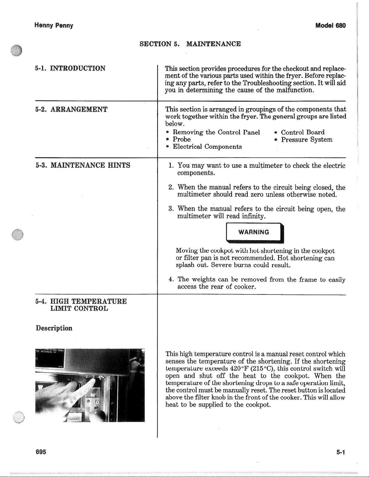
This high temperature control is a manual reset control which
senses the temperature of the shortening. If the shortening
temperature exceeds 420°F (215”C), this control switch will
open and shut off the heat to the eookpot. When the
temperature of the shortening drops to a safe operation limit,
the control must be manually reset. The reset button is located
above the filter knob in the front of the cooker. This will allow
heat to be supplied to the cookpot.
Page 2
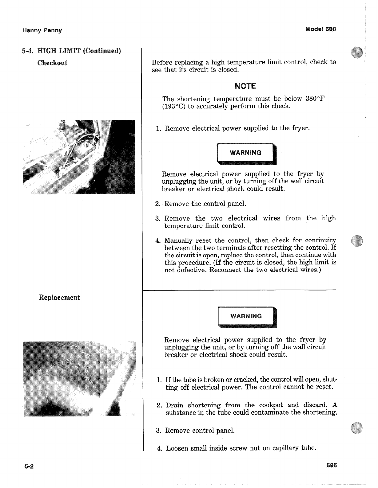
Before replacing a high temperature limit control, check to
see that its circuit is closed.
The shortening temperature must be below 380°F
(193°C) to accurately perform this check.
1. Remove electrical power supplied to the fryer.
Remove electrical power supplied to the fryer by
unplugging the unit, or by turning off the wall circuit
breaker or electrical shock could result.
2. Remove the control panel.
3. Remove the two electrical wires from the high
temperature limit control.
4. Manually reset the control, then check for continuity
between the two terminals after resetting the control. If
the circuit is open, replace the control, then continue with
this procedure. (If the circuit is closed, the high limit is
not defective. Reconnect the two electrical wires.)
Remove electrical power supplied to the fryer by
unplugging the unit, or by turning off the wall circuit
breaker or electrical shock could result.
1. If the tube is broken or cracked, the control will open, shutting off electrical power. The control cannot be reset.
2. Drain shortening from the eookpot and discard. A
substance in the tube could contaminate the shortening.
3. Remove control panel.
4. Loosen small inside screw nut on capillary tube.
Page 3
5. Remove capillary bulb from bulb holder inside the cookpot.
6. Straighten the capillary tube.
7. Remove larger outside nut that threads into pot wall.
8. Remove the two nuts securing the high limit bracket at
the front of the fryer, and remove bracket.
9. Remove the two screws that secure high limit to the high
limit bracket.
10. Remove defective control from control panel area.
11. Insert new control and replace screws.
12. Uncoil capillary line, starting at capillary tube, and insert
through cookpot wall.
To avoid electrical shock or other injury, the capillary
line must run under and away from all electrical power
wires and terminals. The tube must NEVER be in such
a position where it could accidentally touch the electrical power terminals.
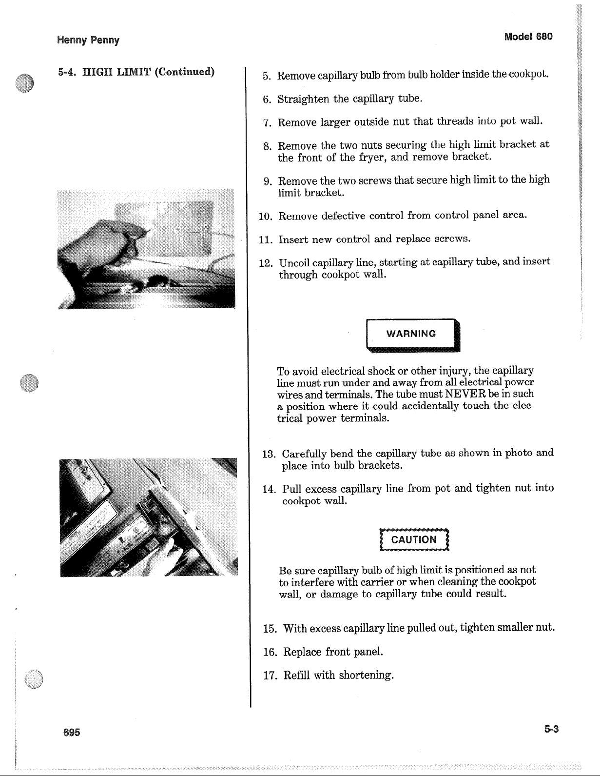
13. Carefully bend the capillary tube as shown in photo and
place into bulb brackets.
14. Pull excess capillary line from pot and tighten nut into
cookpot wall.
Be sure capillary bulb of high limit is positioned as not
to interfere with carrier or when cleaning the cookpot
wall, or damage to capillary tube could result.
15. With excess capillary line pulled out, tighten smaller nut.
16. Replace front panel.
17. Refill with shortening.
Page 4
The Power/Pump Switch is a three way rocker switch with
a center “OFF“ position. With the switch in the POWER
position the fryer will operate. With the switch in the PUMP
position the filter pump will operate, but the heating unit will
not.
Remove electrical power suppled to the fryer by unplugging the unit, or turning off the wall circuit breaker
or electrical shock could result.
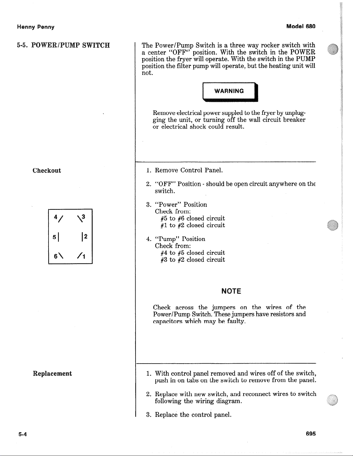
1. Remove Control Panel.
2. “OFF” Position - should be open circuit anywhere on the
switch.
3. “Power” Position
Check from:
#5 to #6 closed circuit
#l to #2 closed circuit
4. “Pump” Position
Check from:
#4 to #5 closed circuit
#3 to #2 closed circuit
Check across the jumpers on the wires of the
Power/Pump Switch. These jumpers have resistors and
capacitors which may be faulty.
1. With control panel removed and wires off of the switch,
push in on tabs on the switch to remove from the panel.
2. Replace with new switch, and reconnect wires to switch
following the wiring diagram.
3. Replace the control panel.
Page 5
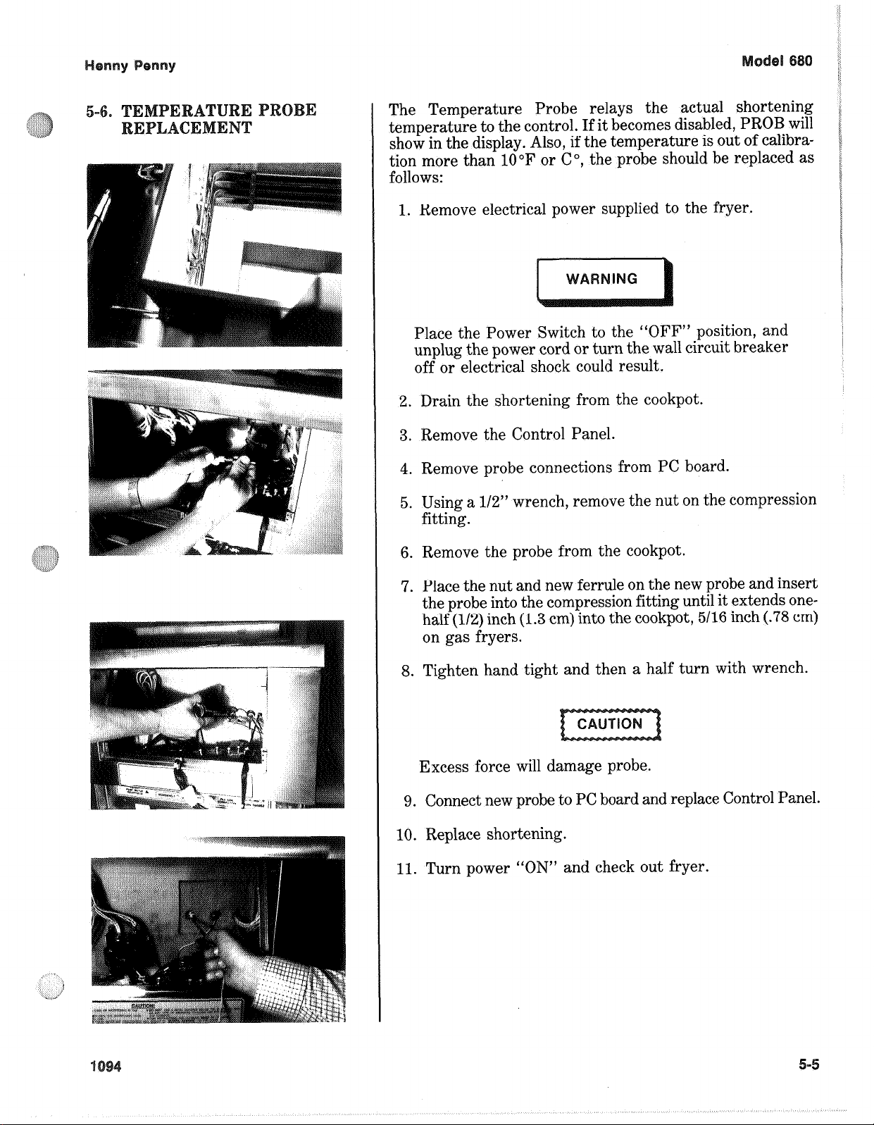
The Temperature Probe relays the actual shortening
temperature to the control. If it becomes disabled, PROB will
show in the display. Also, if the temperature is out of calibration more than 10°F or C”, the probe should be replaced as
follows:
1. Remove electrical power supplied to the fryer.
Place the Power Switch to the “OFF” position, and
unplug the power cord or turn the wall circuit breaker
off or electrical shock could result.
2. Drain the shortening from the cookpot.
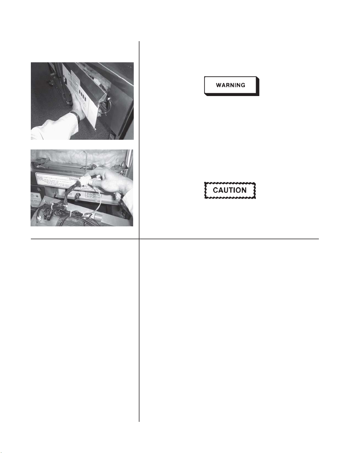
3. Remove the Control Panel.
4. Remove probe connections from PC board.
5. Using a l/2” wrench, remove the nut on the compression
fitting.
6. Remove the probe from the eookpot.
7. Place the nut and new ferrule on the new probe and insert
the probe into the compression fitting until it extends onehalf (l/2) inch (1.3 cm) into the cookpot, 5116 inch (.78 cm)
on gas fryers.
8. Tighten hand tight and then a half turn with wrench.
Excess force will damage probe.
9. Connect new probe to PC board and replace Control Panel.
10. Replace shortening.
11. Turn power
“ON” and check out fryer.
Page 6
Henny Penny Model 680
5-7 COMPLETE CONTROL Should the Control Panel not operate, replace the panel as follows:
PANEL - HENNY PENNY
1. Remove electrical power supplied to the fryer.
Place the Power/Pump Switch in the “OFF” position, and
unplug the power cord and/or turn off the wall circuit breaker,
or electrical shock could result.
2. Remove the two screws securing the Control Panel and lift
panel up and out.
3. Unplug the connectors going to the Control Board.
4. Install new Control Panel.
When plugging connectors into new Control Panel, be sure
connectors are lined-up correctly, such as, connector is not
plugged in backwards, or damage to the board could result.
5-8 PRESSURE REGULATION The Henny Penny Fryer uses pressure as one of the components of
the cooking process. Once the lid is sealed to the cookpot, and the
solenoid valve closes, a deadweight valve maintains the correct
pressure in the cookpot.
The lid has minimal and limited maintenance and repair procedures,
which are addressed in the following sections.
The following is a routine maintenance schedule for the Lid:
Every 90 days
• Clean and reverse lid gasket
Yearly Inspection
• Remove and clean safety relief valve
• Check Lid Gasket for splitting and tears - replace if necessary
• Check Pressure Pads for wear - rotate if necessary
• Check Cam Slide Guides - replace if worn or broken
• Check Lid Rollers - replace if cracked or damaged.
5-6 1005
Page 7
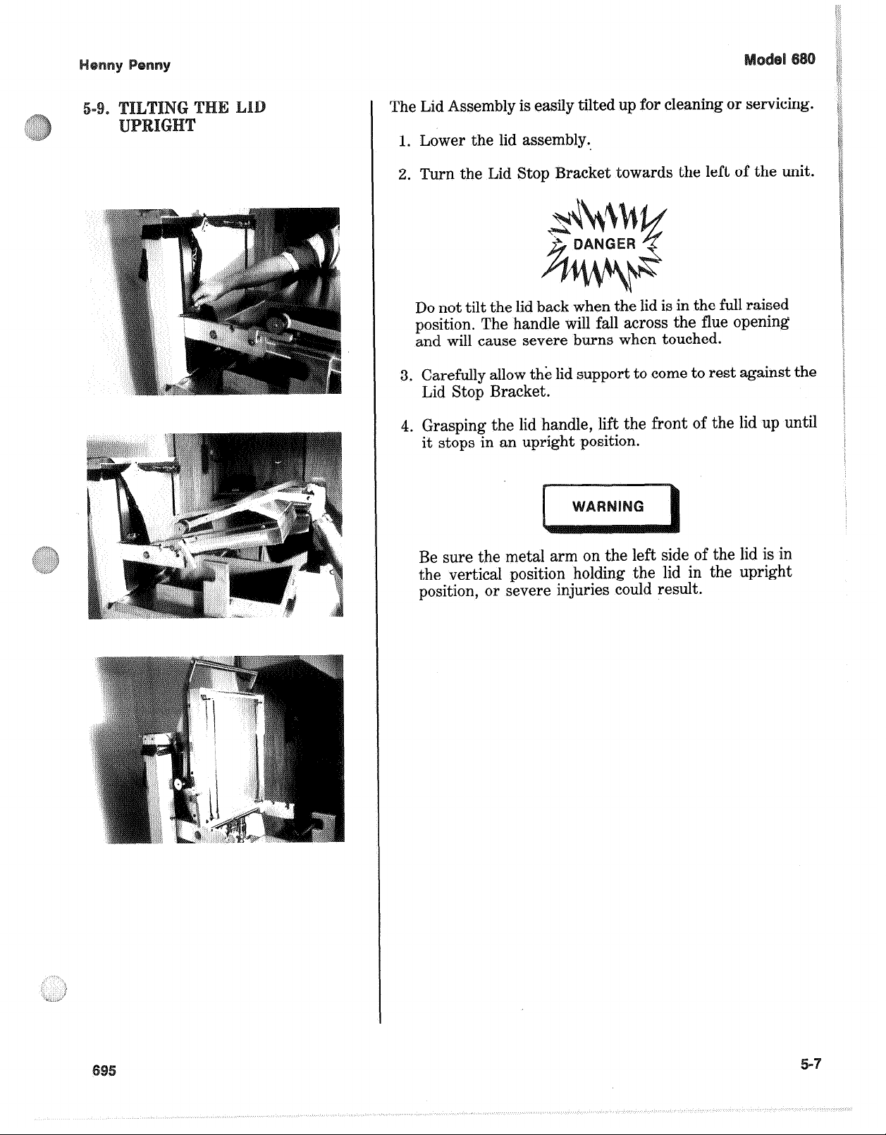
The Lid Assembly is easily tilted up for cleaning or servicing.
1. Lower the lid assembly.,
2. Turn the Lid Stop Bracket towards the left of the unit.
Do not tilt the lid back when the lid is in the full raised
position. The handle will fall across the flue opening
and will cause severe burns when touched.
3. Carefully allow the lid support to come to rest against the
Lid Stop Bracket.
4. Grasping the lid handle, lift the front of the lid up until
it stops in an upright position.
Be sure the metal arm on the left side of the lid is in
the vertical position holding the lid in the upright
position, or severe injuries could result.
Page 8
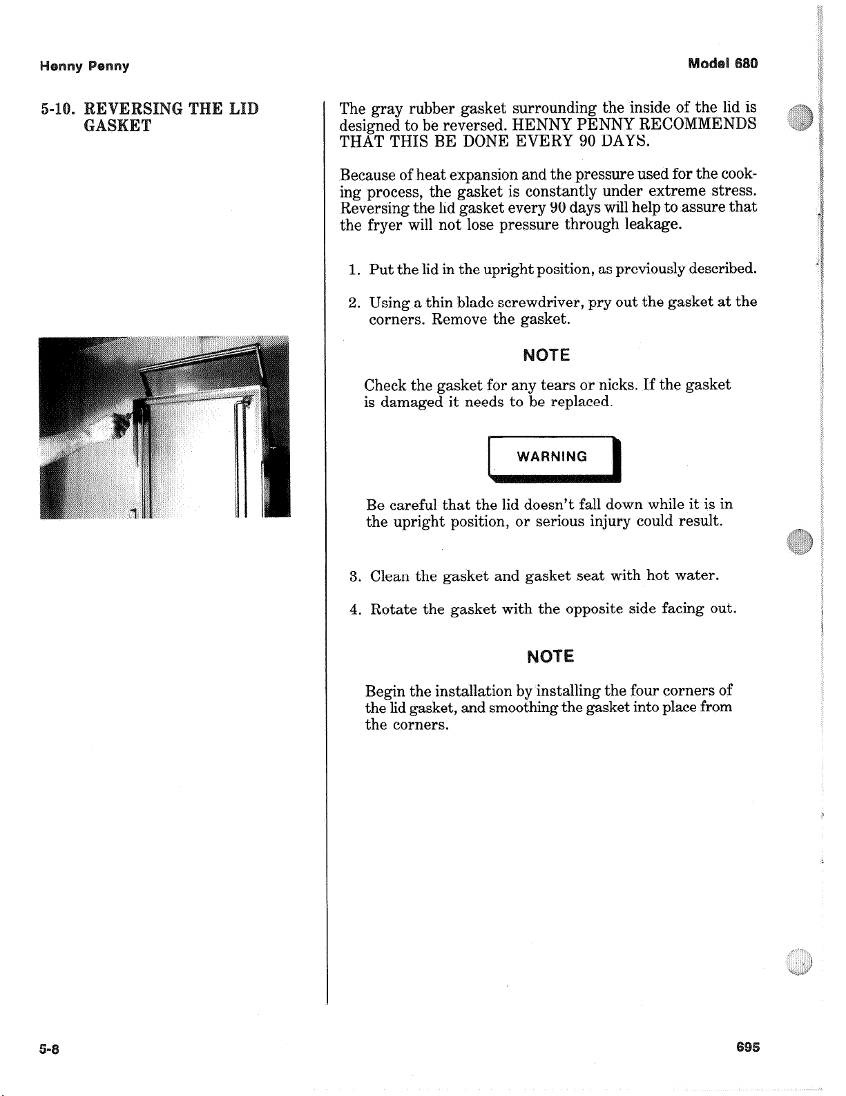
The gray rubber gasket surrounding the inside of the lid is
designed to be reversed. HENNY PENNY RECOMMENDS
THAT THIS BE DONE EVERY 90 DAYS.
Because of heat expansion and the pressure used for the cooking process, the gasket is constantly under extreme stress.
Reversing the lid gasket every 90 days will help to assure that
the fryer will not lose pressure through leakage.
1. Put the lid in the upright position, as previously described.
2. Using a thin blade screwdriver, pry out the gasket at the
corners. Remove the gasket.
Check the gasket for any tears or nicks. If the gasket
is damaged it needs to be replaced.
Be careful that the lid doesn’t fall down while it is in
the upright position, or serious injury could result.
3. Clean the gasket and gasket seat with hot water.
4. Rotate the gasket with the opposite side facing out.
Begin the installation by installing the four corners of
the lid gasket, and smoothing the gasket into place from
the corners.
Page 9
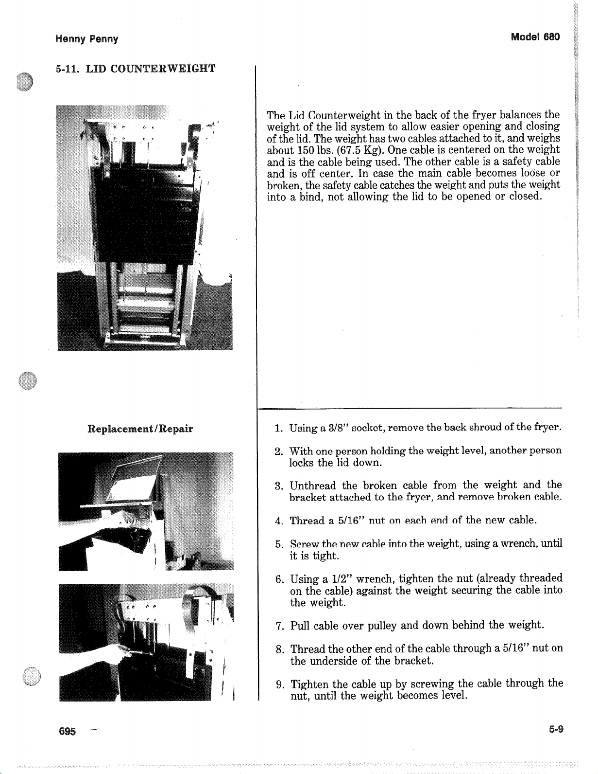
The Lid Counterweight in the back of the fryer balances the
weight of the lid system to allow easier opening and closing
of the lid. The weight has two cables attached to it, and weighs
about 150 lbs. (67.5 Kg). One cable is centered on the weight
and is the cable being used. The other cable is a safety cable
and is off center. In case the main cable becomes loose or
broken, the safety cable catches the weight and puts the weight
into a bind, not allowing the lid to be opened or closed.
1. Using a 3/8” socket, remove the back shroud of the fryer.
2. With one person holding the weight level, another person
locks the lid down.
3. Unthread the broken cable from the weight and the
bracket attached to the fryer, and remove broken cable.
4. Thread a 5116” nut on each end of the new cable.
5. Screw the new cable into the weight, using a wrench, until
it is tight.
6. Using a l/2” wrench, tighten the nut (already threaded
on the cable) against the weight securing the cable into
the weight.
7. Pull cable over pulley and down behind the weight.
8. Thread the other end of the cable through a 5116” nut on
the underside of the bracket.
9. Tighten the cable up by screwing the cable through the
nut, until the weight becomes level.
Page 10

Henny Penny Model 680
5-11. LID COUNTER WEIGHT (CONT’D)
NOTE
The cable should now have some slack in it, with the weights
level.
10. T ighten the nut against the bracket, securing the cable.
11. Replace back shroud. Repair is now complete.
5-12. PRESSURE P AD The pressure pads are plastic strips that the lid cam presses against
to seal the lid.
1. Raise the lid.
2. Remove the four screws securing the lid cover and remove
cover.
3. Push the lid cam back, off of the pressure pads.
4. Using an Allen wrench, remove large bolt securing the pad.
5. Using a Phillips head screw driver, remove the small screw
securing the pad and remove the broken pad.
NOTE
If the pressure pad is worn, but not broken, it can be
reversed 180 degrees, and the other end of the pad used.
6. Install new pad in reverse order.
5-10 1005
Page 11

Henny Penny Model 680
5-13. LID ADJUSTMENT If steam leaks out from around the lid gasket, the pressure pads
could be worn or broken. If the pressure pad is worn, but not
broken, it can be reversed 180 degrees, and the other end of the
pad used. See Section 5-12.
Other problems could cause the steam to leak, such as a
cracked or worn gasket, or gasket not installed properly .
Be certain leaking is not caused by too much pressure
before making any lid adjustments. Fryer should be
operating at 12 psi. Refer to Operating Control Valve
section. All these areas should be checked, or serious burns
could result.
1005 5-11
Page 12

With the carrier and racks installed on the lid, the lid should
stay down, in contact with the pot rim, when the lid is lowered.
The user will then be able to lock the lid in place. If the lid
has a tendency to rise up before getting the lid locked down,
the magnet plate probably needs adjusting. Follow these steps:
1. Remove the six nuts securing the back shroud and remove
back shroud.
2. Loosen the bottom nut under the plate and unscrew both
nuts a couple turns, then lower the lid again to see if the
lid stays down. If not, repeat procedure.
3. Tighten lower nut up against the other nut and install back
shroud - adjustment is now complete.
This is an electromechanical device that causes pressure to be
held in the cookpot. The solenoid valve closes at the beginning
of the cook cycle and opens automatically at the end of the
cook cycle. If this valve should become dirty, or the Teflon seat
nicked, pressure will not build up. The electric fryer uses a
208/240 volt, 60 hertz coil (50 hertz internationally). The gas
uses a 120 volt, 60 hertz coil (208/240 volt, 50 hertz
internationally).
Before starting repair procedures! move the
Power/Pump Switch to the “OFF” position. Disconnect main circuit breaker at the circuit breaker box
and/or unplug service cord from the wall receptacle or
electrical shock could result.
Remove the solenoid wires from the wire nuts which are found
behind the control panel. Check across wires.
RESULTS
208/240 Volt, 60 Hertz 150 Ohms
208/240 Volt, 50 Hertz 230 Ohms
120 Volt, 60 Hertz 50 Ohms
Page 13

Prior to servicing the solenoid valve, it is necessary to
remove the side panel on the right side of the unit.
1. Remove the “tru-arc” retaining clip on top of the coil
housing.
2. Remove the cover.
3. If only the coil is to be replaced, disconnect the two coil
wires at the wire nuts in the coil housing. Remove the coil,
insert new coil, and connect the wires at the wire nuts.
Assemble in reverse order of disassembly.
The wires may be connected in any order.
4. Loosen the screws on the strain relief and pull the wires
through the relief.
5. If the core-disc assembly is sticking due to build up of
shortening, breading, and food particles, proceed with the
following steps:
a. Unscrew the solenoid bonnet assembly from the
solenoid valve body.
b. Remove the solenoid bonnet assembly and bonnet
gasket.
c. Remove the core-disc assembly, core spring retainer,
and the core spring.
d. Wash all these parts in hot water.
If Teflon seals need to be replaced, proceed to Step 6;
otherwise, assemble in reverse order of disassembly.
Assemble valve core and blade with smooth side and
rounded edge of blade toward the disc spring guide.
6. A repair kit (Part No. 17120) is available if any of the seals
must be replaced. If any one seal is defective, they all
should be replaced.
Solenoid body, must be removed from the fryer for
replacement of seals.
Page 14

Henny Penny Model 680
5-16. SOLENOID VALVE
Replacement (Continued)
7. With the bonnet assembly and core-disc assembly
removed, disconnect the two nut fittings. One connects the
solenoid valve to the dead weight system; the other is attached
to the condensation tank.
8. Remove the elbows from the solenoid valve.
9. Remove the two adapter screws which attach the pipe adapter
to the solenoid valve body.
10. Remove the disc spring, guide, and Teflon seat.
11. Clean the valve body.
12. Wet “O” ring around seat with water and insert “O” ring
assembly (flat side first) in valve through “IN” side of body.
Use an eraser end of pencil and press in the Teflon seal until it
snaps into place. BE CAREFUL NOT TO MAR OR NICK
THE SEAT.
NOTE
The smallest nick can cause a pressure leak. Replace all “O”
ring seals that are in the parts kit and reassemble valve.
5-17. OPERATING CONTROL
VA LV E
13. If the complete valve is being replaced, follow steps 1, 2, 3, 4,
5, 7, and 8, in this section.
DO NOT ATTEMPT TO REMOVE THE VALVE CAP
WHILE THE FRYER IS OPERATING, or severe burns or
other injuries could result.
The operating valves are located at the back of the unit. The
valve left of the pressure gauge is a 14 ½ lb. safety relief valve,
and to the right of the pressure gauge, the operating valve.
Valves are working properly, when “OPERATING ZONE”
indicates on the gauge by the pointer. The gauge pointer
should not normally exceed the operating zone. If the pressure
builds to 14 ½ lbs., the safety relief valve opens and releases
pressure from the frypot.
5-14 1005
Page 15

Henny Penny Model 680
5-17. OPERATING CONTROL
VALVE (Continued)
DO NOT MANUALLY ACTIVATE THE SAFETY
RELIEF VALVE. Hot steam will be released from the
valve when the ring is pulled. Keep away from safety
valve exhaust, or severe burns could result.
Cleaning Steps 1. AT THE END OF EACH DAY’S USAGE OF THE
FRYER, THE OPERATING VALVE MUST BE
CLEANED. The fryer must be OFF and the pressure
released. Open the lid and then remove the dead weight
ORIFICE CAP WEIGHT valve cap and dead weight.
Failure to clean the operating valve daily could result in
the fryer building too much pressure. Severe injuries and
burns could result.
2. Wipe both the cap and weight with a soft cloth. Make
certain to thoroughly clean inside cap, the weight seat, and
around valve orifice.
3. Dry the parts and replace immediately to prevent damage
or loss.
5-18. REMOVAL & CLEANING The safety relief valve should be cleaned once a year.
OF SAFETY VALVE
SAFETY VALVE
Do not attempt to remove valve while fryer is operating,
or severe burns or other injuries could result.
1. Remove pressure gauge.
2. Use a wrench to loosen the valve from the elbow, turn
counterclockwise to remove.
1005 5-15
Page 16

Henny Penny Model 680
5-18. REMOVAL & CLEANING 3. Clean inside of the elbow with hot water.
OF SAFETY VALVE NOTE
(Continued) Turn the relief valve towards the left side of the fryer
when reinstalling relief valve.
4. Immerse the safety relief valve in soapy water for 24
hours. Use a 1 to 1 dilution rate. The valve cannot be
disassembled. It is factory preset to open at 14 ½ pounds
of pressure. If it does not open or close, replace it!
DO NOT DISASSEMBLE OR MODIFY THIS VAVLE!
Tampering with this valve could cause serious injuries and
also voids agency approvals and appliance warranty.
5-19. PRESSURE GAUGE
Calibration Steps Recalibrate the pressure gauge if it is out of adjustment.
PRESSURE GAUGE 1. Remove the rim and glass.
2. If the indication hand shows a pressure or vacuum reading
when it should stand at “0”, turn the recalibrator screw in
the same direction in the indicating hand is to be moved
until the hand stands at proper “0” position.
3. Replace the rim and glass.
Cleaning Steps 1. Remove the gauge and check inside the pipefittings from
dead weight body. Make certain fittings are clean and
open.
2. Clean and reinstall the gauge.
5-16 1005
Page 17

The gas control valve is a dual controller, in which one side
of the control valve controls one burner and the other side of
the control valve controls the other burner. If one burner shuts
down, both burners will shut down. The control valve is turned
on or off, it has no pilot position, because the burner does not
require a pilot light.
To avoid injury or property damage, before starting
this procedure, move the Power/Pump switch to the
“OFF” position. Disconnect the main circuit breaker
at the circuit breaker box, or unplug the service cord
at the receptacle. Turn off the main gas supply to the
cooker and disconnect and cap the supply line to fryer,
or possible explosion could result.
A voltage check at the control valve must be taken four
(4) seconds after the Power/Pump switch is turned to
Power position.
1. Turn gas cock knob to the “OFF” position.
2. Pull gas cock knob from control valve.
3. Remove cover from control valve.
4. Using an allen wrench, remove shaft extension from
control valve.
5. Remove left side panel.
6. Unscrew nut from outlet line under the control valve.
7. Measure air slide adjustment from manifold to end of air
slide and slide air slide all the way in.
8. Loosen nut from inlet line going to control valve.
9. Remove wires from control valve.
10. Remove the two screws and nuts from bracket and remove
bracket.
Page 18

11. Remove the three screws from back of control valve and
remove from bracket.
12. Reassemble in reverse order.
Page 19

The blower motor circulates air into the burner area to create
the correct heat for the fryer. If the blower fails, a sensor will
shut the power control valve down.
1. Remove the electrical power supplied to the unit.
Remove electrical power supplied to the unit by unplugging the unit, or by turning off the wall circuit breaker,
or electrical shock could result.
1. Remove both side panels.
2. Remove the nut from the ground wire and remove ground
wire.
3. Disconnect wires at junction box on right, back of fryer.
4. Remove conduit fitting from the blower bracket,
5. Loosen hose clamp and remove hose from blower.
6. Remove two (2) screws from the frame which secures the
bracket, and lift bracket and blower assembly from unit.
7. Remove the three (3) nuts from the back of the blower and
remove the blower from bracket.
8. Replace new blower in reverse order of procedures.
Page 20

The transformer reduces the voltage down to accommodate
those components with low voltage.
1. Remove electrical power supplied to the unit.
Remove the electrical power supplied to the fryer by
unplugging the unit, or by turning off the wall circuit
breaker, or electrical shock could result.
2. Remove the small access panel from the right side panel.
3. Remove the two (2) nuts securing the transformer to the
unit and remove transformer.
4. Remove the wires from transformer.
Mark wires before removal to insure new transformer
is wired correctly.
5. Replace with new transformer in reverse order.
Page 21

The airflow switch senses the flow of air coming from the
blower. If the airflow is reduced below a set amount, the switch
will cut power to the control valve, which shuts the burners
down.
1. Remove electrical power supplied to the unit.
Remove electrical power supplied to the unit by unplugging the unit, or by turning off the wall circuit breaker,
or electrical shock could result.
2. Remove small access panel from right side panel.
3. Pull hose from switch from under fryer.
4. Disconnect wires from switch.
Mark wires before removal to insure new airflow switch
is wired correctly.
5. Remove the two (2) nuts securing switch and remove
switch.
6. Install new airflow switch in reverse order.
Page 22

The ignitor module sends 24 volts to the ignitors and there
is an ignitor module for each ignitor.
1. Remove electrical power supplied to the unit.
Remove electrical power supplied to the unit by unplugging the unit, or by turning off the wall circuit breaker,
or electrical shock could result.
2. Remove small access panel from right side panel.
3. Remove wires from modules.
Mark wires before removal to insure new modules are
wired correctly.
4. Remove the two nuts securing the module and remove
module.
5. Install new module in reverse order.
Upon lifting up on the drain knob, the microswitch should not
be activated, but still be activated by pulling out on the knob.
The nuts on the microswitch can be screwed up or down to
adjust the microswitch.
1. Remove electrical power supplied to the unit.
Remove electrical power supplied to the unit by unplugging the unit, or by turning off the wall circuit breaker,
or electrical shock could result.
2. The following check should be made to determine if the
Drain Switch is defective.
a. Remove the right side panel.
b. Remove bottom nut securing the microswitch and
remove microswitch from unit.
Page 23

c. Check for continuity across the two outside terminals
on the Drain Switch. If circuit is open, the Drain Switch
is bad. The circuit should only be opened by pressing
on the actuator of the Drain Switch.
3. To replace switch, remove &-h-es going to switch and install
new switch in reverse order of above procedures.
4. Test to see if drain valve extension rod actuates the switch.
NOTE: Listen for CLICK of switch while pulling drain
valve extension rod.
The drain valve opens when the drain valve knob is pulled out
and drains the shortening out of the pot.
1. Remove both side panels of unit.
2. Remove cotterpin closest to drain valve.
3. Remove blower (see maintenance section on blower).
4. Unscrew shield from drain valve.
5. Unscrew drain valve from unit.
6. Install new drain valve in reverse order.
Page 24

The 680 fryer has two burner assemblies, one on each side of
the pot. The burners can be ignited with either natural or L.P.
gas.
A blower in the fryer produces the airflow needed for combustion inside the burner chamber. Both burners should be an
orangy-red color while the burners are on continuously (not
pulsing).
A color chart is provided with this manual for comparison. Two observation holes, for easily comparing
the burners, are located in the front of the unit. If the
burners are out of adjustment proceed with the
following:
A. Both burners the same color, but not orangy-red.
1. Remove electrical power supplied to the unit.
Remove electrical power supplied to the unit by unplugging the unit, or by turning off the wall circuit breaker,
or electrical shock could result.
2. Using l/4” socket remove the left side panel.
3. At the back of the unit, locate the blower and the slotted
shield on the front of the blower.
4. Mark the shield in the postion it is in.
5. Loosen the nut securing the shield.
6. Supply power back to the unit and turn Power Switch to
“Power” position.
7. While the burners are igniting continuously, slide the
shield to either open or close the blower opening and
observe the color of the burners until they are both an
orangy-red color. (
8. en the burners are the correct color, tighten the nut
securing the blower shield and replace side panels.
efer to color chart.)
Page 25

urners are different colors.
1. Remove electrical power supplied to the unit.
Remove electrical power supplied to the unit by unplugging the unit, or by turning off the wall circuit breaker,
or electrical shock could result.
2. Using l/4” socket, remove both side panels.
3. Locate the air adjustment behind the control panel on each
side of the unit.
4. Loosen the nuts securing the slide adjustments.
5. Replace power to unit and turn Power Switch to the
“Power” position.
6. While the burners are igniting continously, slide the
adjustment shield open or close until both burners are
orangy-red. (Refer to color chart.)
: Left ‘Burner
7. Tighten nuts on adjustment shields and replace side panels.
I
1. Remove electrical power supplied to the unit.
I
Remove electrical power supplied to the unit by unplug-
ging the unit, or by turning off the wall circuit breaker.
Turn off the main gas supply to the fryer and disconnect and/or cap the main supply line to the fryer, or
possible explosion could result.
2. Remove the left side panel of the fryer.
3. Using 11/16” wrench loosen fitting on gas line going to
burner, and disconnect gas line.
4. Using a Phillips head screwdriver, remove the two screws
securing the condensation deflector onto the frame and
remove deflector.
5. Using 3/8” socket, remove nuts securing burner and drop
burner off unit.
Page 26

6. Remove air hose.
7. Remove pilot orifice and elbows off of faulty burner.
8. Screw pilot orifice and elbows onto new burner.
Use pipe thread sealant on threads on elements.
9. Remove old insulation from burner area.
10. .Using a gasket adhesive, mount the insulation provided
onto the outer surface of burner bracket.
Do not get adhesive onto burner “windows”. It will
discolor, blocking the view.
11. Carefully mount burner assembly onto studs and bracket,
making sure the insulation seals around burner.
ace
t: Right Burner
Avoid striking the ignitor while making the installa-
tion. Also, do not over-tighten the nuts on the studs,
or the studs could break.
12. Fasten condensation deflector onto frame and reconnect
gas line into fitting on new burner.
13. Check for gas leaks per section in the installation portion
of this manual.
14. Place side panel on unit, turn gas on and electrical supply
to unit.
1. Follow steps 1 thru 3 on left burner instructions, except
remove right side panel, and drop down drain rod.
2. Using 3/8” socket, remove nut securing ground wire and
nuts securing the burner assembly. Drop burner assembly
from unit.
3. Follow steps 6 thru 15 on the left burner instructions.
Page 27

The ignitors are electrically energized and the tip of the ignitor
glows red creating combustion in the burner chamber. It then
senses the combustion and sends the message to the modules.
If no combustion occurs, the modules shut the gas off at the
gas valve.
ee
When the Power/Pump switch is in the power position, a red
glow should be seen in each porthole in the front of the fryer.
If no red glow is seen, proceed with the following:
1. Remove electrical power supplied to the unit.
Remove electrical power supplied to the unit by unplugging the unit, or by turning off the wall circuit breaker,
or electrical shock could result.
‘2. Remove the side panel.
3. Locate and remove the wire nuts on the leads to the
ignitors.
4. The ignitor should ohm out at 1.0-6.0 ohms.
The following checks are performed with the wall
circuit breaker closed and the Power/Pump switch in
the Power position. Extreme caution should be taken.
Make connections before applying power, take reading,
and remove power before removing meter leads, or
electrical shock could result.
5. Also, a voltage check can be taken. The ignitor should
receive 24 volts from the ignitor module. If 24 volts is
found from the leads from the modules, then the ignitor
is probably faulty.
If an ignitor is found to be faulty it must be replaced as follows:
1. Remove electrical power supplied to the unit.
Remove electrical power supplied to the unit by unplugging the unit, or by turning off the wall circuit breaker,
or electrical shock could result.
2. emove the side panel.
Page 28

3. Locate wire nuts and disconnect leads.
4. Remove the screw securing the ignitor in the bracket and
remove ignitor.
5. Make sure insulation is in place in the ignitor bracket and
slide the probe through the slot in the bracket.
The probe, or tip of ignitor, is very fragile. Take care
when installing the ignitor.
6. Secure ignitor in place with screw, reconnect wire leads
and replace side panel.
‘7. Reconnect power and test the fryer for proper operation.
The nylatron strips fill the gap in the shroud behind the lid.
1. Secure the lid with the lid stop bracket.
2. Remove one of the tru-arc rings off of the lid pin and knock
the pin out of the lid.
3. Lift the lid from the unit.
The lid weighs 80 lbs. Care should be taken when lifting
the lid to prevent personal injury.
4. With one person on each lid arm, release arms from the
lid stop bracket and allow lid arms to rise all the way up.
Page 29

5. Using a 3/V socket remove the nuts securing the back
shroud and remove the back shroud.
6. Remove bolts securing the strips to the weights, and
remove strips from weights.
7. Remove the screws securing the front shroud, and the nut
securing the exhaust tube bracket.
Page 30

8. Lift the front shroud up and out, over the arms of the lid.
9. Thread the new nylatron strip through the track in the
front shroud.
10. Lining up the holes in the strips, fit the front shroud over
the lid arms and secure to carriage frame.
11. Secure the strips to the weights.
12. Replace back shroud and lid - replacement is complete.
 Loading...