

Page 1

Model 500/561/600
SECTION 3. OPERATING INSTRUCTIONS
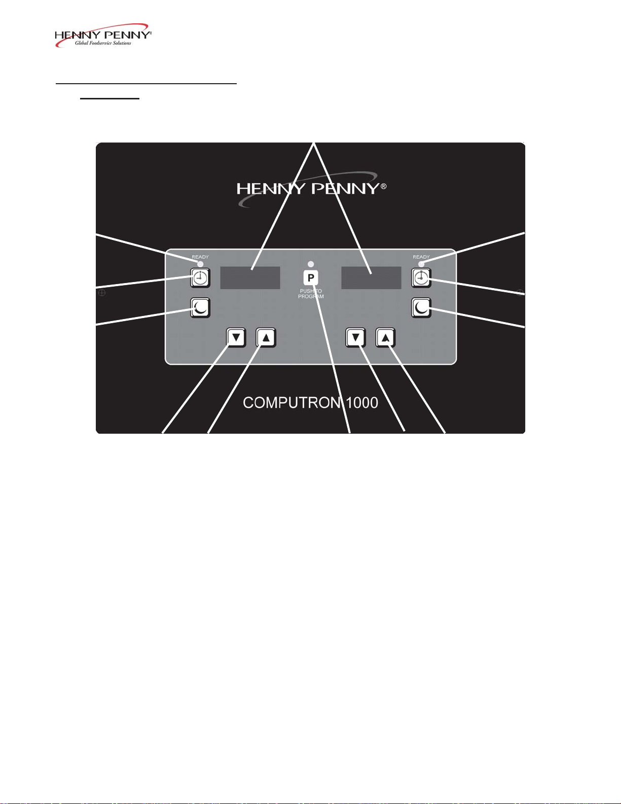
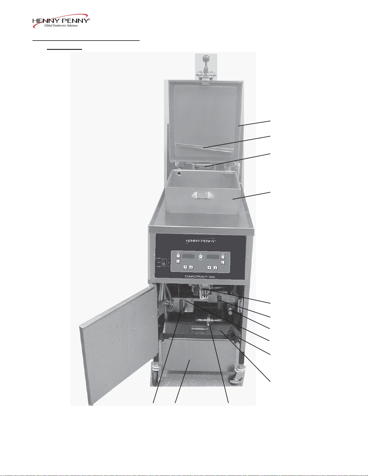
3-1. OPERA TING COMPONENTS C1000 Controls - Reference Figure 3-1.
Fig. Item Description Function
No. No.
3-1 1 Digital Display Shows the shortening temperature, the timer countdown in
the Cook Cycle, and the selections in the Program Mode; the
temperature of the shortening can be shown by pressing
once, or twice to view set-point temperature;
if shortening temperature exceeds 425°F (218°C), the display
reads “E-5, FRYER TOO HOT”
3-1 2 This LED lights when the shortening temperature is within 5°
of the setpoint temperature, signaling the operator that the
shortening temperature is now at the proper temperature for
dropping product into the frypot
3-1 3 The timer buttons are used to start and stop Cook Cycles
3-1 4 The idle buttons are used to start an Idle Mode which reduces
the temperature of the shortening during non-use periods; press
and hold to exit the Idle Mode
3-1 5 The program button is used to access the Program Modes;
also, once in the Program Mode, it is used to advance to the
next parameter
3-1 6 & 7 Used to adjust the value of the currently displayed setting
in the Program Mode and to change set-point temperature of the
shortening
608 3-1
Page 2
3-1. OPERA TING COMPONENTS
(Continued)
Model 500/561/600
1
2
2
3
3
4
6
7
Figure 3-1
589
4
3-2 608
Page 3

Model 500/561/600
3-1. OPERA TING COMPONENTS
(Continued)
Fig. Item Description Function
No. No.
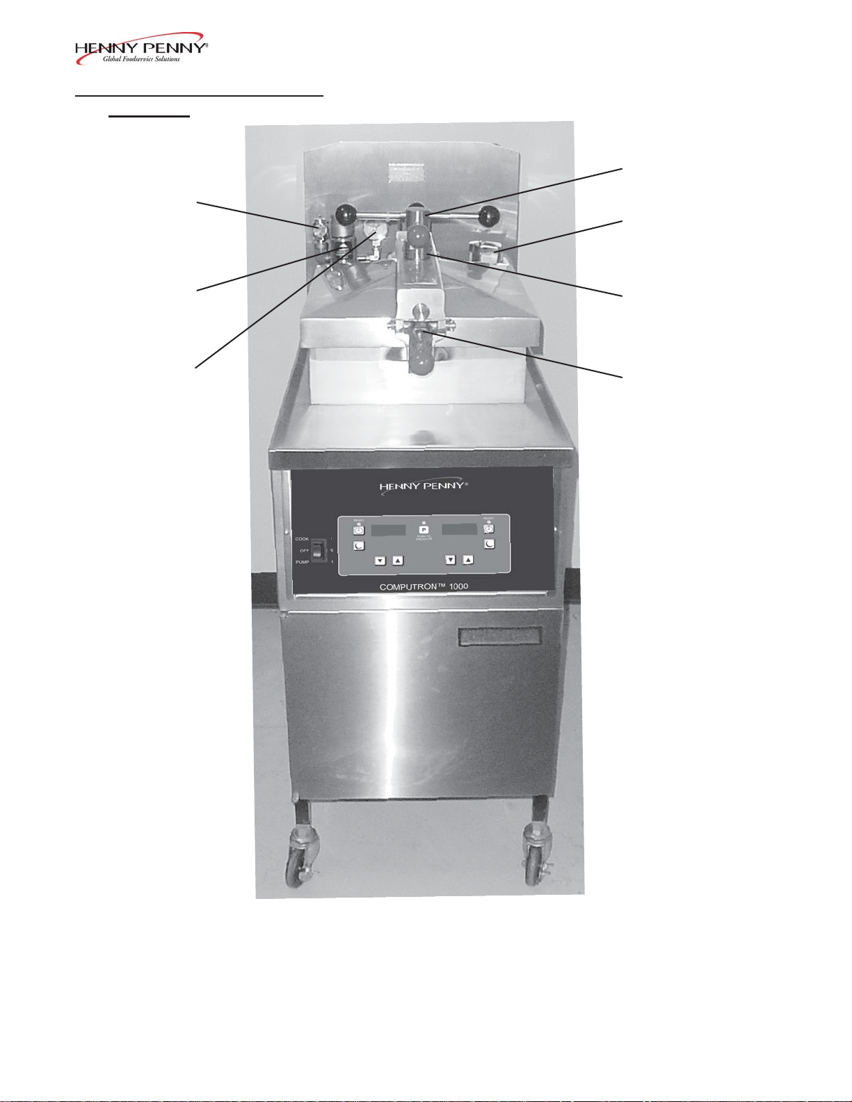
3-3 8 Frypot Holds the cooking shortening and an adequate cold zone for
collection of cracklings
3-3 9 Lid Spring Assists in raising the lid, and then holding it open (it is covered with
a shield)
3-3 10 Condensation Drain This channels the moisture, that collects on the lid liner when the
Channel lid is opened, into the drain line and prevents the moisture droplets
from falling into the shortening
3-3 11 Lid Gasket Provides the pressure seal for the frypot chamber
3-2 12 Lid Latch A spring loaded latch that provides a positive latch to hold the lid
closed; this latch, along with the spindle assembly and lid gasket,
provides a pressure sealed frypot chamber
3-2 13 Spindle Assembly An assembly that is tightened after the lid is latched, and applies
pressure to the top of the lid; the lid gasket then applies pressure
against the frypot rim; after building one pound of internal pressure,
the lid liner pushes a locking pin up into the locking collar, preventing the spindle from being turned while the frypot is pressurized
3-2 14 Lid Limit Stop A threaded adjustable collar used to obtain the proper
tightness between the lid gasket and the frypot rim; done by
controlling the number of clockwise rotations of the spindle
3-2 15 Deadweight This deadweight style, pressure relief valve maintains a constant
Assembly level of steam pressure within the frypot; excess steam is vented
through the exhaust stack
Failure to clean the deadweight assembly daily could
result in the fryer building too much pressure. Severe
injuries and burns could result.
608 3-3
Page 4
Model 500/561/600
3-1. OPERA TING COMPONENTS
(Continued)
Fig. Item Description Function
No. No.
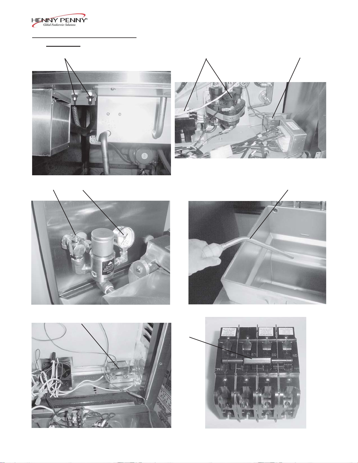
3-2 16 Safety Relief V alve This is an ASME approved spring loaded valve, set at 14.5 psi; if
the deadweight assembly is clogged, this safety valve releases
excess pressure, keeping the frypot chamber at 14.5 psi
(999 mbar); if this occurs, turn the main power switch to OFF to
release all pressure from the frypot
If safety relief valve activates, turn main power switch
to the OFF position. To avoid serious burns and
injuries, have fryer serviced before next use.
3-2 17 Safety Relief V alve Ring
DO NOT PULL THIS RING. SEVERE BURNS FROM
THE STEAM WILL RESUL T .
3-2 18 Pressure Gauge Indicates the pressure inside the frypot
3-5
3-2 19 Solenoid V alve An electromechanical device that causes pressure to be held in the
frypot; the solenoid valve closes at the beginning of the Cook Cycle
and is opened automatically by the controls at the end of the Cook
Cycle; if this valve becomes dirty or the teflon seat nicked, pressure
will not build up and it must be repaired
3-3 20 Drain Valve (Only the A two-way ball valve that is normally close; turn the handle to drain
Handle is Shown) the shortening from the frypot, into the filter drain pan
DO NOT OPEN THE DRAIN V AL VE WHILE FRYPOT
IS UNDER PRESSURE. HOT SHORTENING WILL
EXHAUST AND SEVERE BURNS WILL RESUL T .
3-3 21 Drain Interlock Switch A microswitch that provides protection for the frypot in the event an
operator inadvertently drains the shortening from the frypot while
the main power switch is on; the switch automatically shuts off the
heat when the drain valve is opened
3-4 608
Page 5
Model 500/561/600
3-1. OPERA TING COMPONENTS
(Continued)
Fig. Item Description Function
No. No.
3-3 22 Filter Drain Pan The removable pan that houses the filter and catches the shortening
when it is drained from the frypot; it is also used to remove and
discard old shortening
When moving filter drain pan containing hot shortening,
use extreme care to avoid burns from hot surfaces or
splashing.
3-3 23 Filter Union Connects the filter to the filter pump, and allows easy removal of the
filter and drain pan
3-3 24 Filter V alve When the power switch is in the PUMP position, this two-way
valve directs filtered shortening from the drain pan, back into the
frypot
3-3 25 Condensation Drain A hose used to route the condensation collected within the steam
Line exhaust system, to the condensation pan
3-3 26 Condensation Drain The collection point for the condensation, formed within the steam
Pan exhaust system; remove and empty periodically
3-3 27 Rinse Hose (Optional) A hand-held hose used to rinse food particles from the frypot
3-8 into the filter pan; attaches to a quick disconnect fitting
3-3 28 Gas Control Valve (Gas Controls the gas flow to the burner
Models Only)
3-6
3-7
3-4 30 Breakers-Push Button Protective devices which break the circuit when the current
29 High Temperature Limit A control that senses the temperature of the shortening; if the
temperature of the shortening exceeds the safe operating limit, this
control opens and shuts off the heat to the frypot; when the
temperature of the shortening drops to a safe operation limit, the
control must be manually reset by pressing the red reset button,
located under the control panel, behind the door
Gas Electric
Reset (Electric Models exceeds the rated value
Only)
3-7 31 Contactors (Electric Relays that route power to the heating elements; one relay is in
Models Only) series with the high limit, the other one is in series with the controls;
the standard unit uses 2 electromechanical contactors, while the
computer controlled units have one electromechanical and one
mercury contactor
3-9 32 Circuit Breaker (Single Opens the electrical circuit, and removes power to elements
608 3-5
Phase Only)
Page 6
3-1. OPERA TING COMPONENTS
(Continued)
16
Model 500/561/600
13
19
15
18
14
12
ELECTRIC MODEL
Figure 3-2. Operating Controls
3-6 608
Page 7
3-1. OPERA TING COMPONENTS
(Continued)
Model 500/561/600
11
10
9
8
28
24
27
21
25
22
20
26
23
GAS MODEL
Figure 3-3. Operating Controls
608 3-7
Page 8
3-1. OPERA TING COMPONENTS
(Continued)
Model 500/561/600
17
30
18
Figure 3-4.
31
29
Figure 3-7.
27
Figure 3-5.
29
Figure 3-8.
32
Figure 3-6.
3-8 608
Figure 3-9.
Page 9
3-2. FILLING OR
ADDING SHOR TENING
Model 500/561/600
Before the actual cooking operation and adding shortening to
the frypot, be sure frypot, filter screen assembly , and drain pan
are cleaned. Filter screen assembly and drain pan should be
cleaned with soap and hot water and thoroughly dried before
reassembling. At this time, the frypot should also be cleaned.
Refer to Cleaning the Frypot Section.
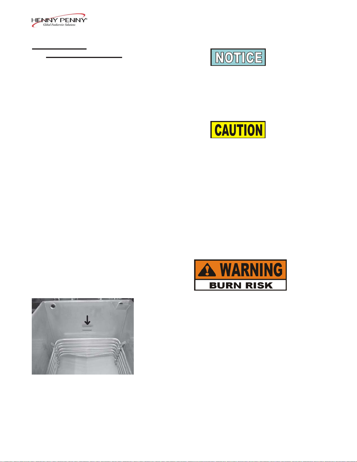
The shortening level must always be at the frypot level
indicator on the rear of the frypot (see photo on next
page). Failure to follow these instructions could r esult in a
fire and/or damage to the fryer.
When using solid shortening, it is recommended to melt
the shortening on an outside heating source before placing it in the frypots. The elements on electric fryers, or the
frypot surface on gas fryers, must be completely
submerged. Fire or damage to the frypot could result.
1. It is recommended that a high quality frying shortening be used
in the fryer. Some low grade shortenings have a high moisture
content and will cause foaming and boiling over.
T o avoid severe burns when pouring hot shortening into
frypot, wear gloves and take care to avoid splashing.
2. The electric model 500 requires 48 lbs. (21.8 kg) of liquid
shortening, and the model 561 requires 65 lbs. (29.5 kg). The
gas model requires 43 lbs. (19.5 kg). Model 500 fryers have
2 level indicator lines inscribed on the rear wall of the frypot,
whereas the models 561 & 600 have only 1 level indicator.
The level indicator lines show the proper shortening levels.
3. Cold shortening should be filled to 1/2-inch (12.7 mm) below
a single level indicator line, and frypots with 2 level indicator
lines, cold shortening should be even with the lower level
indicator line. The shortening expands when heated and
should be at the level indicator line when the shortening is hot,
or the top level indicator line on model 500s.
608 3-9
Page 10
3-3. CARE OF THE
SHORTENING
Model 500/561/600
FOLLOW THE INSTRUCTIONS BELOW TO A V OID
SHORTENING OVERFLOWING THE FR YPOT ,
WHICH COULD RESUL T IN SERIOUS BURNS,
PERSONAL INJUR Y , FIRE, AND/OR PROPERTY
DAMAGE.
1. T o protect, and get the maximum life out of the shortening,
press to lower the temperature to 250° F (135° C) when
the fryer is not in immediate use. Deteriorated shortening
smokes badly , even at lower temperatures.
2. Frying breaded food products requires frequent filtering to keep
the shortening clean. The shortening should be filtered after
every 3 to 6 Cook cycles. For the best quality product,
Do not
exceed 6 Cook Cycles without filtering. Refer to Filtering of
Shortening Section.
3. Maintain the shortening at the proper cooking level. Add fresh
shortening as needed.
4. Do not overload the baskets with product (12 lbs. (5.4 kg.) for
model 600 fryers; 14 lbs (6.4 kg.) for model 500 fryers and
18 lbs. (8.2 kg.) for the model 561) or place product with
extreme moisture content into baskets.
WITH PROLONGED USE, THE FLASHPOINT OF
SHORTENING IS REDUCED. DISCARD THE
SHORTENING IF IT SHOWS SIGNS OF EXCESSIVE
SMOKING OR FOAMING, OR SERIOUS BURNS,
PERSONAL INJUR Y , FIRE, AND/OR PROPERTY
DAMAGE COULD RESUL T .
3-10 608
Page 11

Model 500/561/600
3-4. PRODUCT COOKING
GUIDELINES
The following table provides the suggested frying times and temperatures
for single-stage cooking, using the Henny Penny Pressure Fryer combined with our special blends of PHT Fryer Breading Mixes.
All the suggested time and temperature settings are for a 10
pound (4.5 kg) load.
Product (size per piece) T emperature Time(Min.)
Chicken 315ºF (157ºC) 10-11
(2-1/4 lbs (1 kg), 8 or 9 pieces)
Fish 315ºF (157ºC) 3.5
(4 ozs (.11 kg))
Shrimp 315ºF (157ºC) 2
T rout 315ºF (157ºC) 5
(10 to 16 ozs (.28-.45 kg))
Pork Chops 315ºF (157ºC) 5
(4 to 5 ozs,(.11-.14 kg),
1
/2 to 3/4 ins (12.7-19 mm) thick)
Ribs 275°F) (135ºC) 14
(2-1/2 lb (1.13 kg) rack)
Cubed Steak 315ºF (157ºC) 5
(6 to 10 ozs,(.17-.28 kg),
1/4 to 1 in (6.4-25.4 mm) thick)
V eal Cutlet 315ºF (157ºC) 4
(4 ozs (.11 kg))
Potatoes 315ºF (157ºC) 8
(10 lbs (4.5 kg), cut in wedges)
608 3-11
Page 12
Model 500/561/600
3-5. CHICKEN FRYING
PROCEDURES
The following is a description of the operating procedures for fryers
with the Computron 1000 controls.
1. Check to see that all control switches are off and the drain and
filter valves are in the closed position.
2. Remove the basket from the frypot and leave lid open.
3. Make sure frypot is filled with shortening to the proper level.
Refer to filling and Adding
4. Make sure electrical power is connected to fryer. Gas units,
make sure gas lines are connected to fryer and gas valve is
turned on - See
DOWN PROCEDURE Section
5. Display shows “OFF” until power switch is turned to the ON
position. Display now shows the cook time and the unit automatically goes into the Melt Cycle until the shortening temperature reaches 230°F (110°C). The control then automatically exits
the Melt Cycle.
GAS PILOT & BURNER LIGHTING AND SHUT
Shortening Section.
.
The PFG-600 series pressure fryer has several safety devices
which shuts-down the gas supply when they are activated. The
above procedures should be followed to restart the open fryer
and if the shut down is repeated, a qualified technician should be
notified.
The Melt Cycle may be bypassed, if desired, by pressing and
holding for 3 seconds.
Do not bypass the Melt Cycle unless enough shortening has
melted to completely cover the curved surface of the gas
frypots and elements on electric fryers. If Melt Cycle is
bypassed before all gas frypot or elements are covered,
excessive smoking of the shortening, or a fire will result.
5. Once out of the Melt Cycle, the shortening is heated until
lights and the cook time is displayed.
6. Using the basket handle, thoroughly stir shortening to stabilize the
temperature throughout the frypot.
Step 6
3-12 608
7. Once the shortening temperature has stabilized at the setpoint
temperature, lower the basket into the frypot.
Page 13
3-5. CHICKEN FRYING
PROCEDURES (Continued)
Model 500/561/600
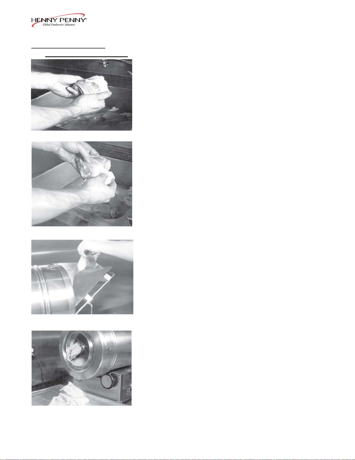
8. T ake the chicken parts, either 4 or 5 cut-up chickens, from the
cooler and place in a scullery sink. W ash the chicken and, at this
point, break the thigh from the joint of the backbone.
Step 8
9. Remove any excess fat from the thigh.
10. Remove the chicken from the water and drain slightly , but allow
the parts to remain moist.
Step 9
Step 11
11. If a breading machine is used, fill the breading drum with
approximately 8 to 10 pounds of PHT Breading Mix. Feed the
moist but drained pieces into the chute at one end of the breader .
12. Allow the breaded pieces to fall onto a tray as they come out of
the breader drum.
Step 12
608 3-13
Page 14

Model 500/561/600
3-5. CHICKEN FRYING
PROCEDURES (Continued)
Step 13
13. If a breading machine is not used, the food should be placed in
the dry mix and hand tumbled so that each piece of food is
completely covered.
14. Knock off any excess breading and place the breaded product
on a tray for cooler storage. Place a damp cloth over the
breaded food to retain moisture. The breaded food should be
held for a minimum of 30 minutes before frying so that it can
absorb spices from the breading and so that breading can
better adhere to the product.
15. Determine the time and temperature settings according to the
type of product to be fried.
16. Set the controls to the desired temperature and time. See C1000
Programming Instructions Section.
Before placing the product into the basket, make certain that
the shortening is at the correct frying temperature for the type
of product. Also check that is on.
Step 17
17. Place the food into the submerged basket by first putting in the
largest pieces (thighs and drumsticks). This gives the large
and more difficult pieces time to fry a few extra seconds in
the shortening. Leave the lid open.
Use care to prevent splashing hot shortening. Severe
burns can result.
Do not overload, or place product with extreme moisture
content into the basket.
The maximum load size is 12 lbs.
(5.4 kg.) for model 600 fryers; 14 lbs (6.4 kg.) for model
500 fryers and 18 lbs. (8.2 kg.) for the model 561. Failure
to follow these directions can result in shortening overflowing the frypot. Serious burns, fire, or damage to the unit
could result.
18. Lift the basket slightly out of the shortening and shake it,
causing the pieces to separate. Return the basket to the shortening. Doing this will prevent white spots on the finished
product.
3-14 608
Page 15

Model 500/561/600
3-5. CHICKEN FRYING
PROCEDURES (Continued)
19. Remove the basket handle and close the lid quickly .
Latch the lid with the lid latch.
20. Tighten the lid spindle clockwise to properly secure and seal the
lid. Align the red knob on the spindle with the red knob on the
lid latch.
LID MUST BE LA TCHED PROPERL Y OR PRESSURIZED SHORTENING AND STEAM MAY ESCAPE
FRYPOT . SEVERE BURNS WILL RESUL T .
Step 19
21. Press .
22. Within a few minutes, the pressure gauge should increase to the
OPERA TING ZONE. If it does not recheck the procedures
and then refer to the Troubleshooting Section.
Step 20
During operation, perform the following checks:
• Make sure the pressure gauge indicator needle reads in the
Operating Zone. A full load must be placed in frypot upon
using new shortening, or not enough steam will be generated
to obtain full cooking pressure.
- if pressure does not build, check T roubleshooting Section
or call your local Henny Penny service agent if need be
• Check the drain and filter valve for leaks
23. At the end of the Cook Cycle (the timer reaches zero), the fryer
automatically depressurizes, the timer buzzer sounds, and the
display flashes “DONE”. Press button to turn off alarm.
DO NOT LIFT HANDLE OR FORCE LID LA TCH
OPEN BEFORE PRESSURE GAUGE READS “0”
PSI. ESCAPING STEAM AND SHORTENING
WILL RESULT IN SEVERE BURNS.
608 3-15
Page 16

Model 500/561/600
3-5. CHICKEN FRYING
PROCEDURES (Continued)
24. After the pressure drops to zero, turn the spindle
counterclockwise approximately one turn.
Do not spin or flip the spindle cross arm when opening the
lid. Damage to the acme nut inside the cross bar could
result.
25. Raise the lid promptly to allow most of the condensation on the
lid to drain down and out through the drain channel and not
back into the shortening.
To avoid damage to the hinge, do not let the lid slam up
against its backstop.
26. Insert the handle into the basket. Lift the basket and hang it on
the side of the frypot to drain. Allow the product to drain
approximately 15 seconds before dumping it onto a tray .
Step 26
27. Place the product into a warming cabinet immediately .
28. Before frying the next load, wait until is on, indicating
the shortening has reheated.
IF THE SHORTENING TEMPERA TURE EXCEEDS
420°F (216°C), IMMEDIA TELY SHUT OFF THE
POWER AT THE MAIN CIRCUIT BREAKER AND
HAVE THE FRYER REP AIRED. IF SHOR TENING
TEMPERA TURE EXCEEDS ITS FLASHPOINT , FIRE
WILL OCCUR, RESULTING IN SEVERE BURNS
AND/OR PROPERTY DAMAG
E.
3-16 608
Page 17

Model 500/561/600
3-6. C1000 PROGRAMMNG
INSTRUCTIONS
3-7. C1000 SPECIAL
PROGRAMMNG
Timer Programming
1. Anytime the cook time is displayed, press under the appropri-
ate display to change the cook time.
Set-Point Temperature Programming
1. Press once to view the actual shortening temperature and
press again to view the set-point temperature.
2. While the set-point temperature is in the display , press
to change the set-point temperature.
If “LOCK” shows in display when pressing ,
the controls are locked and must be unlocked before changing
the time or set-point temperature. See C1000 Special
Programming Section.
Special Programming is used to set the items below:
Fahrenheit or Celsius
Initialize System
Lock or Unlock Controls
Fryer Type – Open or Pressure
Heat Source – Electric; Gas w/electronic ignition
Vat Type - Full or Split
Oil T ype - Solid or Liquid
1. T o enter Special Programming, turn off power switch
(either side). Press and hold and turn the power
switch back on.
2. “SPEC” “PROG” followed by, “DEG” “°F” or “°C”.
Us e to choose “°F” or “°C”.
3. Press and “INIT” shows in the display.
Press and hold and display shows “In-3”,
“In-2”, “In-1” followed by “Init Sys” “DONE DONE”. The
controls now are reset to factory parameters, the time set to
0:00 and temperature 190°F or 88°C.
4. Press and “LOCK” or “UNLOCK” shows in the displays. Use to choose “LOCK” or “UNLOCK.
5. Press an d “FRYR” shows in left display and the right
display should show “PRES”. Use to change from
“OPEN” to “PRES” if needed.
1209 3-17
Page 18

Model 500/561/600
3-7. C1000 SPECIAL
PROGRAMMNG
(Continued)
6. Press and “HEA T” shows in the display . Use
to change the heat source: “ELEC” for electric models; “GAS”
for units with standing pilot; SSI for units with solid state
ignition.
7. Press and “V AT” and “FULL” should show in the
displays if controls are set to “PRES” in step 5.
8. Press and “MEL T” and “Solid” or “LIQD” shows in the
displays.
shortening, or “LIQD”, if using liquid shortening.
Use to choose “Solid”, if using solid
9. Press and hold to exit Special Programming at any time.
3-18 1209
Page 19

Model 500/561/600
3-8. REGULAR MAINTENANCE
SCHEDULE
Procedure Frequency
Filter pump motor protector- As required
manual reset
Filtering of shortening Every 3 to 6 frying cycles
Cleaning the Optional Crumb pan As required
Filter pump problem prevention As required
Changing of shortening As required
Changing the filter envelope As required
Changing the charcoal filter As required
Cleaning the frypot Before changing the shortening
Cleaning the deadweight valve Daily
Night closing procedures Daily
Check optional rinse hose W eekly
for deterioration
Reversing the lid gasket Quarterly
As in all food service equipment, the Henny Penny pressure fryer does
require care and proper maintenance. The table below provides a
summary of scheduled maintenance.
Lid lubrication Quarterly
Limit stop adjustment Quarterly
Check tightness of spreader bars Quarterly
Clean safety relief valve Annually
3-9. FIL TER PUMP
MOTOR
PROTECTORMANUAL RESET
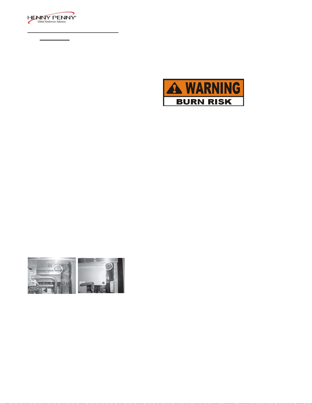
The filter pump motor is equipped with a manual reset button,
located on the rear of the motor, in case the motor overheats. W ait
about 5 minutes before attempting to reset this protective device to
allow motor to cool. The filter motor is on the rear of the fryer . It
takes some effort to push the reset, and a screwdriver can be used to
help reset the button.
Electric fryers with serial numbers of HB013JB & below , and gas
fryers with serial numbers of GA085JB & below , can push the reset
button, by removing the access panel on the left side panel of the unit.
To prevent burns caused by splashing shortening, turn
the unit’s main power switch to the OFF position before
resetting the filter pump motor’ s manual r eset protection
device.
708 3-19
Page 20

Model 500/561/600
3-10. FIL TERING OF
SHORTENING
Step 2
Frying breaded food requires frequent filtering. T aste the cold shortening every day for flavor. W atch the shortening for foaming during frying
cycles. Discard the shortening as soon as it shows signs of foaming.
Clean the frypot as follows each time the shortening is changed or
filtered:
1. Turn the main power switch to the OFF position. Remove and
clean the fry basket in soap and water. Rinse thoroughly .
The best results are obtained when the shortening is
filtered at the normal frying temperature.
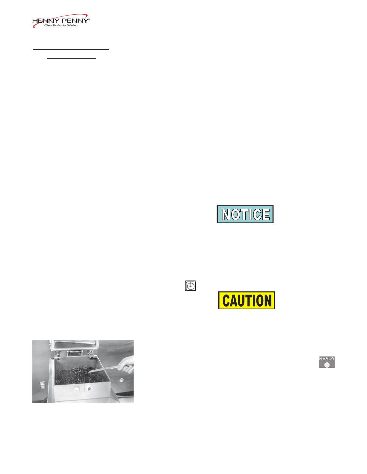
2. Use a metal spatula to scrape any build-up from the sides of
the frypot. Do not scrape heating element on electric units,
or the curved portion of the gas frypot.
Scraping the electric fryer elements, or the curved portion
of the gas frypot, produces scratches in these surfaces
causing breading to stick and burn.
Step 4
Do not bang the pot scraper, or other cleaning utensil, on
the frypot rim. Damage to the frypot rim could result and
the lid may not seal properly during a cook cycle.
The filter drain pan must be as far back under fryer as
it will go, and the cover in place. Be sure the hole in the
cover lines up with the drain before opening the drain.
Failure to follow these instructions causes splashing of
shortening and could result in personal injury .
Surfaces of fryer and basket will be hot. Use care when
filtering to avoid getting burned.
3. Open the drain valve very slowly , half a turn at first and then
slowly to the full open position. This will prevent excessive
splashing of the hot shortening as it drains into the filter drain pan.
4. As the shortening drains from the frypot, use fryer brushes
(Henny Penny part number 12105 includes both brushes) to
clean the side of the frypot and the heating elements (if electric
unit). If the drain fills with breading, use the white brush to push
the breading into the filter pan.
3-20 708
Page 21

Model 500/561/600
3-10. FIL TERING OF
SHORTENING
(Continued)
5. When all of the shortening has drained, scrape or brush the sides
and the bottom of the frypot.
6. Rinse the frypot as follows:
a. Close the drain valve.
b. Open the filter valve.
c. Lower lid and hold closed.
d. Move the main power switch to the PUMP position. Carefully
open the lid to see if the shortening is returning properly . Fill
frypot 1/3 full, then turn off pump.
F AILURE TO HOLD THE LID CLOSED SO THA T
THE FIRST SURGE OF THE RETURNING SHOR T ENING WILL NOT SPLASH OUT OF THE FR YPOT ,
WILL RESULT IN SEVERE BURNS.
Step 6e
Step 7a
IF THERE ARE AIR BUBBLES COMING UP IN THE
SHORTENING, IT’S POSSIBLE THA T THE FIL TER
CONNECTION A T THE UNION ON THE FILTER
TUBE IS NOT TIGHTENED PROPERL Y. IF SO,
TURN OFF THE PUMP AND USE PROTECTIVE
CLOTH OR GLOVE WHEN TIGHTENING THE
UNION. THIS UNION WILL BE HOT AND SEVERE
BURNS COULD RESUL T .
e. W ash down and scrub the sides of the frypot. Use “L” brush to
clean the heating elements.
f. After the sides and bottom are cleaned, open the
drain valve.
7. If an optional filter rinse hose is available on your fryer, the
following cleaning procedure may be used.
a. Attach the filter rinse hose with its quick disconnect fitting
to the male fitting inside the door next to the filter valve handle.
T o do this, slide back the spring ring on the female side of the
quick disconnect fitting and let it snap into place over the male
half of the fitting.
708 3-21
Page 22

Model 500/561/600
3-10. FIL TERING OF
SHORTENING
(Continued)
Step 7b
b. While holding the wooden handle, make sure the hose nozzle
is pointed down into the bottom of the frypot. Pull the lid
down over the nozzle, close the filter valve, and move the
main power switch to the PUMP position. Hold nozzle
carefully to avoid excessive splashing.
Use care to prevent burns caused by splashing of
hot shortening.
c. Rinse the frypot interior . Especially work on hard to clean areas,
like the frypot bottom. On electric models clean around heating
elements.
d. After suf ficient rinsing with shortening, close the drain valve.
e. Turn the main power switch to the OFF position.
Step 7c
Step 7f
ONL Y CONNECT AND DISCONNECT THE FIL TER
RINSE HOSE WHEN THE MAIN POWER SWITCH
IS IN THE OFF POSITION. ALSO, USE A DRY
CLOTH OR GLOVE TO AVOID BURNS. FAILURE
TO DO THIS COULD RESULT IN SEVERE BURNS
FROM HOT SHORTENING SPRA YING FROM THE
MALE FITTING .
f. Detach the hose. Raise the fitting end of hose high for a minute
to allow the remaining shortening in the hose to drain into the
frypot.
8. Pump all the shortening out of the filter pan and back into the
frypot. Close lid during first surge of pumping.
3-22 803
Page 23

Model 500/561/600
3-10. FIL TERING OF
SHORTENING
(Continued)
9. When the pump is pumping air only , the shortening in the frypot
will appear to be boiling. Close the filter valve first and then
move the main power switch from PUMP to OFF . This will
keep the filter pump and lines from filling up with shortening.
When bubbling occurs, immediately close the filter valve. This
prevents aeration of the shortening, therefore increasing
shortening life.
10. Check the level of the shortening if necessary , until it reaches the
level indicator line on the rear wall of the frypot, or the top level
indicator line on model 500s..
Step 9
11. After completing the filtering operation, empty and
replace the condensation drain pan.
Step 11
12. If frying is to be continued at this time, move the main power
switch back to the ON position, and allow time for reheating of
the shortening.
205 3-23
Page 24

Model 500/561/600
3-11. CLEANING THE
OPTIONAL CRUMB PAN
Electric Gas
Electric Gas
The crumb pan allows improved filtration process because finer, hard
to filter particles are now retained within the pan. Crumb accumulation
within the filter pan is reduced, and it is quicker to pump the shortening
back into the frypot. Also, cracklings can be taken out of the crumb
pan and used for gravy .
See crumb pan removal procedure below:
1. Drain shortening from frypot to access pan.
2. Insert provided handle at angle to get by support nubs on shaft.
Use protective cloth or gloves when removing the crumb
pan. The crumb pan and frypot surfaces may be hot and
burns could result.
3. T urn handle until notches in handle are below support nubs on
shaft.
Electric Gas
4. Lift crumb pan out of frypot.
Electric Gas
5. Clean frypot of all crumbs before reinstalling crumb pan and
returning shortening to frypot.
3-24 703
Page 25

Model 500/561/600
3-12. FIL TER PUMP
PROBLEM
PREVENTION
3-13. CHANGING THE
FILTER ENVELOPE
The following steps will help prevent filter pump problems:
1. Make certain the charcoal filter is installed with the smooth
side down and the arms on the frame are clamped down over
the protrusions on the outside of the frame.
2. The filter valve is to be closed at all times during frying.
3. Pump all the shortening from the filter lines by running the filter
pump motor until the shortening in the frypot appears to be
bubbling or boiling.
The filter envelope should be changed after 10-12 filterings or whenever it becomes clogged with crumbs. Proceed as follows:
1. Move the main power switch to the OFF position.
2. Remove and empty the condensation drain pan.
3. Disconnect the filter union and remove the drain pan from
under the frypot. If available, a drain pan may have casters
under it, allowing easy transport of filter pan and filter
assembly .
Step 3
Step 4
Filter Union
This union could be hot! Use protective cloth or glove,
or severe burns could result.
If the filter pan is moved while full of shortening, use
care to prevent splashing, or burns could result.
4. Lift the screen assembly from the drain pan.
5. W ipe the shortening and crumbs from the drain pan. Clean
the drain pan with soap and water, then thoroughly rinse with
hot water.
703 3-25
Page 26

3-13. CHANGING THE
FILTER ENVELOPE
(Continued)
Model 500/561/600
6. Unthread the suction standpipe from the screen assembly .
Step 7
7. Remove the crumb catcher and clean thoroughly with soap and
water. Rinse thoroughly with hot water .
Step 8
Step 9
8. Remove the filter clips and discard the filter envelope.
9. Clean the top and bottom filter screen with soap and water.
Rinse thoroughly with hot water .
Be sure that the filter screens, crumb catcher, filter clips,
and the suction standpipe are thoroughly dry before
assembly of filter envelope as water will dissolve the
filter paper.
10. Assemble the top filter screen to the bottom filter screen.
3-26 703
Page 27

3-13. CHANGING THE
FILTER ENVELOPE
(Continued)
Model 500/561/600
11. Slide the screens into a clean filter envelope.
12. Fold the corners in and then double fold the open end.
13. Clamp the envelope in place with the two filter retaining clips.
Step 12
14. Replace the crumb catcher screen on top of the filter paper .
Screw on the suction standpipe assembly .
15. Place complete filter screen assembly back into filter drain pan
and slide pan back into place beneath the fryer .
16. Connect the filter union by hand. Do not use a wrench to tighten.
17. Slide the condensation drain pan back into place. The fryer is
now ready to operate.
803 3-27
Page 28

Model 500/561/600
3-14. CHANGING THE
CHARCOAL FIL TER
Step 3
The charcoal filter should be changed every day or whenever it becomes clogged with crumbs. Proceed as follows:
1. Move the main power switch to the OFF position.
2. Remove and empty the condensation drain pan.
3. Disconnect the filter union and remove the filter drain pan from
beneath the frypot.
Use protective cloth or glove when disconnecting the
filter union and removing the charcoal filter assembly , or
severeburns could result.
If the filter pan is moved while full of shortening, use
care to prevent splashing, or severe burns could result.
4. An optional filter pan dolly can be used to safely transport filter
pan filled with hot shortening.
Step 7
Step 7
5. Discard shortening, or pump shortening back into frypot.
6. W earing protective gloves or using a cloth, remove the charcoal
filter assembly from drain pan.
7. Set charcoal filter assembly on a counter or table and turn the 4
clips securing the charcoal pad frame, and pull frame from
assembly .
3-28 205
Page 29

3-14. CHANGING THE
CHARCOAL FIL TER
(Continued)
Model 500/561/600
8. Remove and discard old filter pad. Clean and dry pan, frame,
and grid thoroughly .
9. Place grid, frame and new charcoal filter pad in assembly with
smooth side facing the grid and secure with clips.
3-15. CLEANING
THE FRYPOT
Step 9
10. Slide the drain pan back into place under the fryer and connect
the filter union by hand. Do not use a wrench to tighten.
11. Slide the condensation drain pan back into place. The fryer is
now ready to operate.
After the initial installation of the fryer, as well as before every change
of shortening, the frypot should be thoroughly cleaned as follows:
1. Turn the main power switch to OFF , and unplug unit from the
wall receptacle.
Moving either the frypot, or filter pan, while containing hot
shortening is not recommended. Hot shortening can splash
out. Severe burns could result.
The filter drain pan must be as far back under the fryer as it
will go, and the cover in place. Be sure the hole in the cover
lines up with the drain before opening the drain. Failure to
follow these instructions causes splashing of shortening and
could result in personal injury .
703 3-29
Page 30

Model 500/561/600
3-15. CLEANING
THE FRYPOT
(Continued)
2. If hot shortening is present in the frypot, it must be drained by
slowly opening the drain valve handle one half turn. Leave for
a few minutes, then slowly open the valve to the full open
position.
3. Close the drain valve and discard the shortening in the filter pan.
Then install the filter drain pan under the fryer, leaving out the
filter screen assembly .
4. Fill the frypot to the level indicator with hot water. Add 4 to 6
ounces of fryer cleaner (Henny Penny part number 12101) to
the water and mix thoroughly . The fry basket can be placed
inside frypot for cleaning.
Always wear chemical splash goggles or face shield and
protective rubber gloves when cleaning the frypot as the
cleaning solution is highly alkaline. A void splashing or
other contact of the solution with your eyes or skin.
Severe burns and possible blindness can result. Care
fully read the instructions on the cleaner . If solution
comes in contact with your eyes, rinse thoroughly with
cool water and see a physician immediately .
5. Turn main power switch to the POWER position set controls to
195ºF (90.5° C).
DO NOT CLOSE LID WITH WA TER AND/OR
CLEANER IN FRYPOT . WA TER UNDER PRESSURE BECOMES SUPERHEA TED. WHEN LID IS
OPENED, ESCAPING WA TER AND STEAM WILL
RESUL T IN SEVERE BURNS.
Henny Penny has the following cleaners available:
Foaming Degreaser - Part no. 12226
PHT Liquid Cleaner - Part no. 12135
PHT Dry Powder Cleaner - Part no. 12101
See your local distributor for details.
3-30 708
Page 31

Model 500/561/600
3-15. CLEANING
THE FRYPOT
(Continued)
6. When comes on and solution temperature is at
195ºF (90.5° C), immediately move the main power switch to
OFF.
Watch the cleaning solution constantly to make sure it
does not boil over causing damage to controls.
If the cleaning solution in the frypot starts to foam and
boil over , immediately turn the power switch to OFF
and do not try to contain it by closing the fryer lid
or severe burns could result.
Pour a cup of hot cleaning solution (taken from the frypot) into
the condensation tower to keep it free and clean.
7. Let the cleaning solution stand for 15 to 20 minutes with the
unit off.
8. Using the fryer brush (Henny Penny part number 12105),
scrub the inside of the frypot, the lid liner, and around the
countertop of the fryer.
Do not use the cleaning solution on the lid or the lid hinge.
These parts are aluminum and will corr ode if the PHT
cleaner comes in contact with them.
Do not use steel wool, other abrasive cleaners, or cleaners/sanitizers containing chlorine, bromine, iodine, or
ammonia chemicals as these will deteriorate the stainless
steel material and shorten the life of the unit.
Do not use a water jet (pressure sprayer) to clean unit or
component damage could result.
9. After cleaning, open the drain valve and drain the cleaning solu-
tion from the frypot into the drain pan and discard.
10. Replace the empty drain pan, close the drain valve and refill
the frypot with plain hot water to proper level.
708 3-31
Page 32

Model 500/561/600
3-15. CLEANING
THE FRYPOT
(Continued)
3-16. CLEANING THE
DEADWEIGHT ASSEMBLY
11. Add approximately 8 ounces of distilled vinegar and bring the
solution to 195º F (90.5° C).
12. Using a clean brush, scrub the interior of the frypot and lid liner.
This will neutralize the alkaline left by the cleaning compound.
13. Drain the vinegar rinse water and discard.
14. Rinse down the frypot, using clean hot water.
15. Thoroughly dry the drain pan, and the frypot interior .
Make sure the inside of the frypot, the drain valve opening, and all
the parts that will come in contact with the new shortening are as
dry as possible.
16. Replace the clean filter assembly in the drain pan and install
under fryer.
17. Refill the fryer with fresh shortening.
At the end of each day , the deadweight assembly valve must be
cleaned as follows:
DO NOT A TTEMPT T O REMOVE DEADWEIGHT
CAP WHILE FRYER IS OPERA TING. SEVERE
BURNS OR OTHER INJURIES WILL RESUL T .
1. Turn the main power switch to the OFF position. Be sure all
pressure has been released and open the lid.
2. Unscrew the deadweight cap and remove the cap and dead
weight.
Deadweight cap may be hot. Use protective cloth or
glove, or burns could result.
Step 3
Failure to clean the deadweight assembly daily could
result in the fryer building too much pressure. Severe
injuries and burns could result.
3. Clean the exhaust tube with stainless steel brush (Henny Penny
part number 12147).
3-32 708
Page 33

3-16. CLEANING THE
DEADWEIGHT
ASSEMBLY (Continued)
Model 500/561/600
4. Clean the deadweight cap and weight in hot detergent water .
Make certain to thoroughly clean the inside of the valve cap and
the deadweight.
5. Clean the deadweight orifice and the inside of the deadweight
assembly body with a clean lint-free cloth.
6. Dry the deadweight and deadweight assembly cap.
7. Replace deadweight and deadweight assembly cap. Finger
tighten the cap.
3-17. NIGHT CLOSING
PROCEDURES
Step 6
At the end of each day or shift, perform the following procedures:
1. Filter the shortening per Filtering of Shortening Section.
2. Move the main power switch to the OFF positions.
3. Place the fryer basket in a sink for cleaning.
4. Clean the deadweight assembly per Cleaning the Deadweight
Assembly Section.
5. Dump the water from the condensation drain pan.
If disconnection of the cable restraint is necessary, be
sure to reconnect the restraint after the fryer has been
returned to its originally installed position.
708 3-33
Page 34

Model 500/561/600
3-18. OPERA TING INSTRUC-
TIONS FOR OPTIONAL
DIRECT-CONNECT
SHORTENING SYSTEM
Figure 1
1. Connect the female quick disconnect, that is attached to
the hose in the rear of the fryer, to the correct male quick
disconnect at the wall. Once attached, the hose can
remain connected unless the fryer is moved. Figure 1.
In order for the system to work properly, attach the hose
to the shortening return line only.
2. Open the drain valve and drop the shortening from the
desired frypot, into the drain pan.
Figure 2
3. Once all shortening is gone from frypot, turn the red
handle counterclockwise, into the down position and
hold. Figure 2.
4. While holding the handle down, turn the POWER/PUMP
switch to the PUMP position. Shortening is now pumped
from the drain pan.
5. Once all the shortening is out of the drain pan, turn the
POWER/PUMP switch to the OFF position.
6. T urn red handle back to original position.
7. Frypot is now ready for fresh shortening.
3-34 703
Page 35

Model 500/561/600
3-19. REVERSING THE
LID GASKET
Reversing the lid gasket helps to prevent early failure of lid gasket
and the loss of pressure during a cook cycle.
1. Back the 4 lid liner screws (2 on each side) out about 1/2 inch
(12.7 mm).
2. Using a thin blade screwdriver pry out the gasket at the corners,
and then pull gasket from lid.
Check the gasket for any tears or nicks. If the
gasket is damaged, it needs to be replaced.
3. Clean the gasket and gasket seat with hot water and cleaning
detergent. Rinse with clean hot water .
4. Install the gasket with the “good” side out and tighten the 4
screws.
Install the four corners of the lid gasket. Smooth
the gasket into place, working from the corners
towards the middle of each side.
1002 3-35
Page 36

Model 500/561/600
3-20. LID LUBRICA TION T o extend the life of lid components, lubricate the ball seat and
spindle, following the steps below .
1. Close and latch the lid, and turn the spindle counterclockwise
until it stops.
2. Press down on the front of the cross bar , pull out the release
pin, lift the latch, and raise the cross bar .
3. Using spindle lube (part no. 12124), lubricate the ball seat in
the center of the lid cover .
4. Turn spindle clockwise until it stops and then lubricate the
threads on the spindle using the spindle lube.
5. Turn the spindle counterclockwise until it stops, line up the lid
cover with the cross bar, pull the release pin out, and firmly
press the cross bar back into place.
6. The fryer is now ready for use.
3-36 703
Page 37

Model 500/561/600
3-21. LIMIT STOP
ADJUSTMENT
T o extend the life of the lid gasket and help prevent steam
leakage, check the limit stop adjustment quarterly , following the
steps below .
1. Close and latch lid, and turn spindle counterclockwise until
it stops.
2. Using a 3/16” Allen wrench, loosen the 2 set screws on the
outer collar of the limit stop.
3. Turn the inner collar clockwise until it stops.
Step 2
Insert a small screwdriver or Allen wrench in the hole in the
inner collar to assist you in turning the collar .
4. T urn spindle clockwise until it stops. The lid gasket is now
touching the frypot rim.
Step 3
5. From the front of the fryer , turn the spindle at least 3/4 of a
turn, but not over 1 turn. One of the spindle arms should be
lined up with the red ball of the latch, at this time.
6. Slightly turn the spindle past this position, so it should show in
about the 7 o’clock position.
The 7 o’clock position is only to allow slight additional turning
of the spindle to relieve any side pressure against the locking
pin. Side pressure holds the pin in the locked position, even
after all the pressure has released.
When adjustment is complete, if a black ball on the spindle is
lined up with the red ball on the latch, unscrew the black ball
and the red ball on the spindle and change places on the
spindle. The red ball on the spindle should now line up with
the red ball on the latch.
703 3-37
Page 38

Model 500/561/600
3-21. LIMIT STOP
ADJUSTMENT
(Continued)
3-22. CLEANING THE
SAFETY RELIEF
VALVE
7. Turn the inner collar counterclockwise until it stops against the
bottom hub of the spindle.
8. Tighten Allen screws.
If the lid cover fails to seal properly , steam escapes from
around the gasket during frying. Readjust the limit stop, this
time turning the spindle 1 full turn after the initial contact of the
lid gasket with the frypot rim (step 5).
DO NOT A TTEMPT TO REMOVE THE SAFETY
VALVE WHILE FRYER IS OPERA TING, OR SEVERE
BURNS OR OTHER INJURIES WILL RESUL T .
SAFETY V AL VE
DO NOT DISASSEMBLE OR MODIFY THIS
SAFETY RELIEF V AL VE. TAMPERING WITH THIS
VALVE COULD CAUSE SERIOUS INJURIES AND
WILL V OID AGENCY APPROV ALS AND APPLIANCE W ARRANTY .
1. Remove deadweight cap and deadweight.
2. Use a wrench to loosen the valve from the pipe elbow , turn
counterclockwise to remove.
3. Clean the inside of the pipe elbow with hot water .
Turn the safety relief valve towards the rear of the fryer when
reinstalling the relief valve.
4. Immerse the safety relief valve in a soapy water solution
for 24 hours. Use a 1 to 1 dilution rate. The valve cannot
be disassembled. It is factory preset to open at 14-1/2
pounds of pressure (999 mbar). If it does not open or close,
it must be replaced.
3-38 703
Page 39

Model 500/561/600
3-23. CHECK & TIGHTEN
ELEMENT SPREADER
BARS (Model 500 only)
T o extend the life of the temperature probe, high limit, and elements,
every 90 days check the tightness of the element spreader bar screws,
following the steps below:
Drain shortening and allow fryer to cool before proceeding with the following steps. Surfaces of the fryer will be
hot and burns could result.
1. Check that all spreader bars are in place (4 sets), and using a
5/16” socket or wrench, tighten all the element spreader
screws.
If the bolts or spreaders are missing or damaged, order
kit no. 14685 from your nearest Henny Penny distributor.
2. Pump shortening back into frypot and unit is now ready for
use.
205 3-39
Page 40

Model 500/561/600
3-24. SEASONAL
SHUTDOWN
3-25. CUT -UP
FRIED CHICKEN
1. Drain and clean the frypot per Cleaning the Frypot Section.
2. Turn the main circuit breaker OFF and unplug the electrical cord,
if possible.
3. On gas models turn the gas valve to OFF . Shut off the gas valve
on the main gas supply line.
4. Close the lid but do not tighten the spindle.
5. Remove and clean the condensation drain pan.
6. Clean the inside of the steam exhaust tank on gas
models.
1. Cut 2 1/2 to 2 3/4 pound (1.13-1.3 kg) net weight birds into 8 or
9 pieces. Nine pieces allows you to serve 3 three-piece dinners
from each bird.
2. W ash the chicken parts and drain thoroughly . Break the thigh
bone from the front of the backbone and remove excess fat
from the thigh.
3. Bread the pieces in advance (if using Henny Penny Fryer
Breading Mix) so that the breaded chicken will be held at
least 30 minutes before frying. Breading in advance will give
the breading an opportunity to permeate the meat and adhere
better to the product. The pieces can be breaded and held
refrigerated for as long as 24 hours before frying. This
procedure eliminates continuous breading and will save labor .
4. Frying temperature for best results is 320°F (160°C) for 10 to 11
minutes.
3-40 703
Page 41

Model 500/561/600
3-26. CHICKEN
QUARTERS
3-27. BARBECUED
CHICKEN
3-28. FRIED
PORK CHOPS/
VEAL CUTLETS
Follow the “Cut-up Fried Chicken” procedure above, allowing an
additional 2 to 3 minutes for frying. The portions are larger and will
need the additional frying time.
1. Whole halves (2 to 2-1/2 lbs. (.9-1.13 kg) less giblets): Prepare
the birds by washing and draining thoroughly .
2. Place them into the fryer whole or cut into halves.
3. The frying temperature is 310°F (154°C) for 12 minutes for
halves. The whole birds should be fried at 310°F (154°C) for
15 minutes.
4. After the frying has been completed, place the halves or whole
birds into a pan of warm barbecue sauce. For best results, allow
a minimum of 30 minutes in barbecue sauce before serving.
1. W ash and drain the chops thoroughly .
2. Bread the pork chops (4 oz. portion, 1/2-inch to 3/4-inch
(.11 kg, 12.7-19 mm) thick)with the Henny Penny Fryer Mix.
3. Fry at 315°F (157°C) for 5 minutes. If the chops are larger ,
allow an additional minute for each 2 ounce (.06 kg) increase per
portion.
3-29. BARBECUED
PORK CHOPS
1. Fry the chops (4 oz. (.11 kg) portion) for 5 minutes at 305°F
(152°C).
2. After frying has been completed, place the chops in warm
barbecue sauce.
3. The chops should remain in the barbecue sauce for
30 minutes prior to serving at 150°F (66°C) minimum.
3-30. BARBECUED RIBS 1. Prepare racks of ribs (racks of 2-1/2 pounds (1.13 kg) and
under) by trimming excessive fat.
2. Cut the ribs into proper portions for serving before preparing.
(Ribs lightly breaded with Henny Penny Fryer Mix before frying
gives additional flavor.)
703 3-41
Page 42

Model 500/561/600
3-30. BARBECUED RIBS
(Continued)
3-31. TOP SIRLOIN
STEAK AND
FILET MIGNON
3-32. FISH FILLETS
3. The ribs should be fried for 13 minutes at 275°F (135°C).
4. Ribs should then be brushed well on both sides with
barbecue sauce, or placed in a pan of warm sauce.
5. Hold ribs in a sauce at 150ºF (66°C), for 30 minutes so
flavor can permeate.
6. Racks of ribs that exceed 2-1/2 pounds (.9 kg) will need addi
tional time for frying. Use approximately 15 minutes for 3-pound
(1.4 kg) racks.
1. For steak (6 to 8 oz. (.17-.23 kg) portions, normal thickness)
that is to be served brown outside with pink inside, fry for 4
minutes at 315°F (157°C).
2. T o serve a steak with brown outside and no pink inside,
fry for 7 to 8 minutes at 315°F (157°C).
1. Clean, wash and drain. Use 4 oz. (.11 kg) size pieces.
2. Marinate or bread.
3. Fry for 3-1/2 minutes at 315°F (157°C).
3-33. FROG LEGS
1. Clean, wash, and drain.
2. Marinate or bread.
3. Fry for 7 minutes at 315°F (157°C).
3-34. OYSTERS
1. Clean, wash, and drain. Remove shell particles.
2. Bread.
3. Fry at 2 minutes at 315°F (157°C).
3-35. SHRIMP 1. Clean, wash, and drain.
2. Bread.
3. Fry for 3 minutes at 315°F (157°C).
3-42 703
Page 43

Model 500/561/600
3-36. ROCK
LOBSTER T AIL
3-37. POT A TOES
3-38. CORN ON THE COB
3-39. CAULIFLOWER
1. Clean, wash, and drain.
2. Fry for 6 minutes at 315°F (157°C).
1. Use U.S. No. 1 grade Idaho potatoes, unpeeled.
W ash and cut into 8 wedges. Drain and bread.
2. Fry for 8 minutes at 315°F (157°C). If smaller potatoes are
used, time may be reduced.
1. Clean, wash, and drain.
2. Fry for 4 minutes at 315°F (157°C).
1. Clean, wash, and drain.
2. Cut into 1 inch (25.4 mm) pieces.
3. Bread.
4. Fry for 2 minutes at 315°F (157°C).
703 3-43
 Loading...