

Page 1
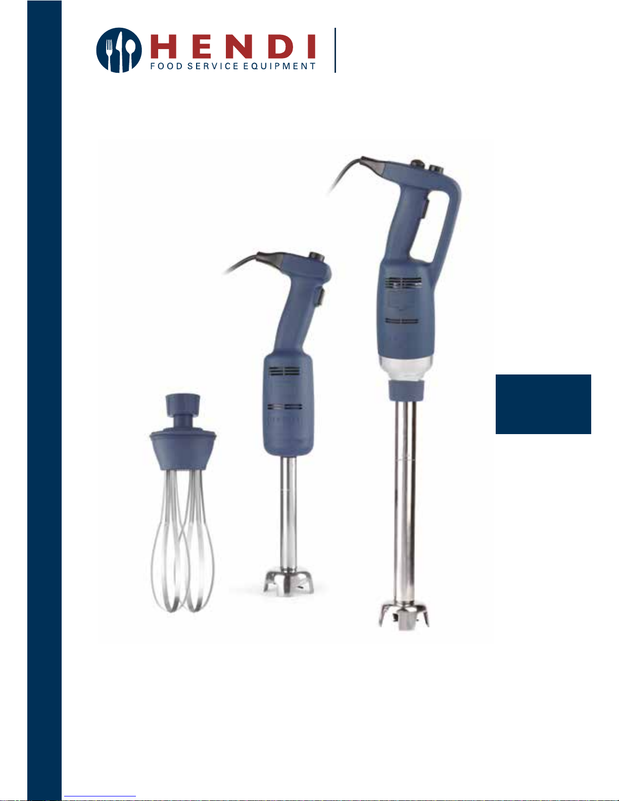
Item: 222140
222171
222188
222133
IMMERSION BLENDER
User manual
Gebrauchsanweisung
Gebruiksaanwijzing
Instrukcja obsługi
Mode d’emploi
Istruzioni per l’utente
Instrucţiunile utilizatorului
Руководство по эксплуатации
Οδηγίες χρήσης
You should read this user manual carefully before
using the appliance.
Bevor Sie das Gerät in Betrieb nehmen, sollten
Sie diese Gebrauchsanweisung aufmerksam lesen.
Alvorens de apparatuur in gebruik te nemen dient
u deze gebruiksaanwijzing aandachtig te lezen.
Przed uruchomieniem urządzenia należy koniecznie
dokładnie przeczytać niniejszą instrukcję obsługi.
Lisez attentivement ce mode d’emploi avant d’utiliser
l’appareil .
Prima di utilizzare l’apparecchio in funzione leggere
attentamente le istruzioni per l’uso.
Citiţi cu atenţie prezentul manual de utilizare înainte
de folosirea aparatului.
Внимательно прочитайте руководство пользователя
перед использованием прибора.
Πρέπει να διαβάσετε αυτές τις οδηγίες χρήσης
προσεκτικά πριν χρησιμοποιήσετε τη συσκευή.
Page 2
Keep these instructions with the appliance.
Diese Gebrauchsanweisung bitte beim Gerät aufbewahren.
Bewaar deze handleiding bij het apparaat.
Zachowaj instrukcję urządzenia
Gardez ces instructions avec cet appareil.
Conservate le istruzioni insieme all’apparecchio.
Păstraţi maualul de utilizare alături de aparat.
Хранить руководство вместе с устройством.
Φυλάξτε αυτές τις οδηγίες μαζί με τη συσκευή.
For indoor use only.
Nur zur Verwendung im Innenbereich.
Alleen voor gebruik binnenshuis.
Do użytku wewnątrz pomieszczeń.
Pour l’usage à l’intérieur seulement.
Destinato solo all’uso domestico.
Doar pentru uz la interior.
Использовать только в помещениях.
Για χρήση μόνο σε εσωτερικό χώρο.
Page 3

3
EN
Dear Customer,
Thank you for purchasing this Hendi appliance. Before using the appliance for the first time, please read
this manual carefully, paying particular attention to the safety regulations outlined below.
Safety regulations
• This appliance is intended for commercial use only and must not be used for household
use.
• The appliance must only be used for the purpose for which it was intended and designed.
The manufacturer is not liable for any damage caused by incorrect operation and
improper use.
• Keep the appliance and electrical plug away from water and any other liquids. In the
event that the appliance should fall into water, immediately remove plug from the socket
and do not use until the appliance has been checked by a certified technician. Failure to
follow these instructions could cause a risk to lives.
• Never attempt to open the casing of the appliance yourself.
• Do not insert any objects in the casing of the appliance.
• Do not touch the plug with wet or damp hands.
• Danger of electric shock! Do not attempt to repair the appliance yourself. In case of
malfunctions, repairs are to be conducted by qualified personnel only.
• Never use a damaged appliance! Disconnect the appliance from the electrical outlet and
contact the retailer if it is damaged.
• Warning! Do not immerse the electrical parts of the appliance in water or other liquids.
Never hold the appliance under running water.
• Regularly check the power plug and cord for any damage. If the power plug or power cord
is damaged, it must be replaced by a service agent or similarly qualified persons in order
to avoid danger or injury.
• Make sure the cord does not come in contact with sharp or hot objects and keep it away
from open fire. To pull the plug out of the socket, always pull on the plug and not on the
cord.
•
Ensure that the cord (or extension cord) is positioned so that it will not cause a trip hazard.
• Always keep an eye on the appliance when in use.
•
Warning! As long as the plug is in the socket the appliance is connected to the power source.
• Turn off the appliance before pulling the plug out of the socket.
• Never carry the appliance by the cord.
• Do not use any extra devices that are not supplied along with the appliance.
• Only connect the appliance to an electrical outlet with the voltage and frequency
mentioned on the appliance label.
• Connect the power plug to an easily accessible electrical outlet so that in case of
emergency the appliance can be unplugged immediately. To completely switch off the
appliance pull the power plug out of the electrical outlet.
Page 4

4
EN
• Always turn the appliance off before disconnecting the plug.
• Never use accessories other than those recommended by the manufacturer. Failure to do
so could pose a safety risk to the user and could damage the appliance. Only use original
parts and accessories.
• This appliance is not intended for use by persons (including children) with reduced
physical, sensory or mental capabilities, or lack of experience and knowledge.
• This appliance must not be used by children under any circumstances.
• Keep the appliance and its cord out of reach of children.
• Always disconnect the appliance from the mains if it is left unattended or is not in use,
and before assembly, disassembly or cleaning.
• Never leave the appliance unattended during use.
Special safety regulations
• This appliance is intended only for pureeing, emulsifying and mixing hot and cold food
commercially. It allows for preparation of soups, puree, creams, marzipan mass, cheese
creams, etc. directly in the pot. Any other use may lead to damage to the appliance or
personal injury.
• Use the appliance as described in the manual.
• This appliance should be operated by trained personnel in kitchen of the restaurant,
canteens or bar staff, etc.
• Always disconnect the appliance from the power supply if it is left unattended and before
assembly, disassembly or cleaning.
• Never let the blade face towards anybody while operating the appliance.
• Do not touch the blade and moving parts. Keep fingers, hair, clothing and utensils away
from all moving parts.
• Dry the appliance and all accessories before connecting to the power supply and prior to
attaching the accessories.
• Danger of hand injury! Handle the blade with great care as it is very sharp.
• Never add ingredients to the container while the appliance is operating.
• Warning! Unplug immediately after use, before removing or changing accessories.
For mounting the wall bracket of item 222133 on the wall, please read carefully below im
-
portant safety precautions:
• Installation should be done by the qualified technician for the reason of safety.
• Verify prior to installation that the wall can safely support the loading of whole set of
appliance & its accessories.
• Make sure that no electrical wires, water, gas or other lines are located around the in
-
stallation location.
• Consult a qualified contractor or installer for assistance if you are not certain about the
structure of the wall.
• Tighten the screws firmly but do not over tighten. Over tightening can damage the screws,
greatly reducing the holding power.
Page 5
5
EN
• During installation, keep away the pet and children.
• Warning! Do not put other things except the appliance to prevent overloading of the
bracket.
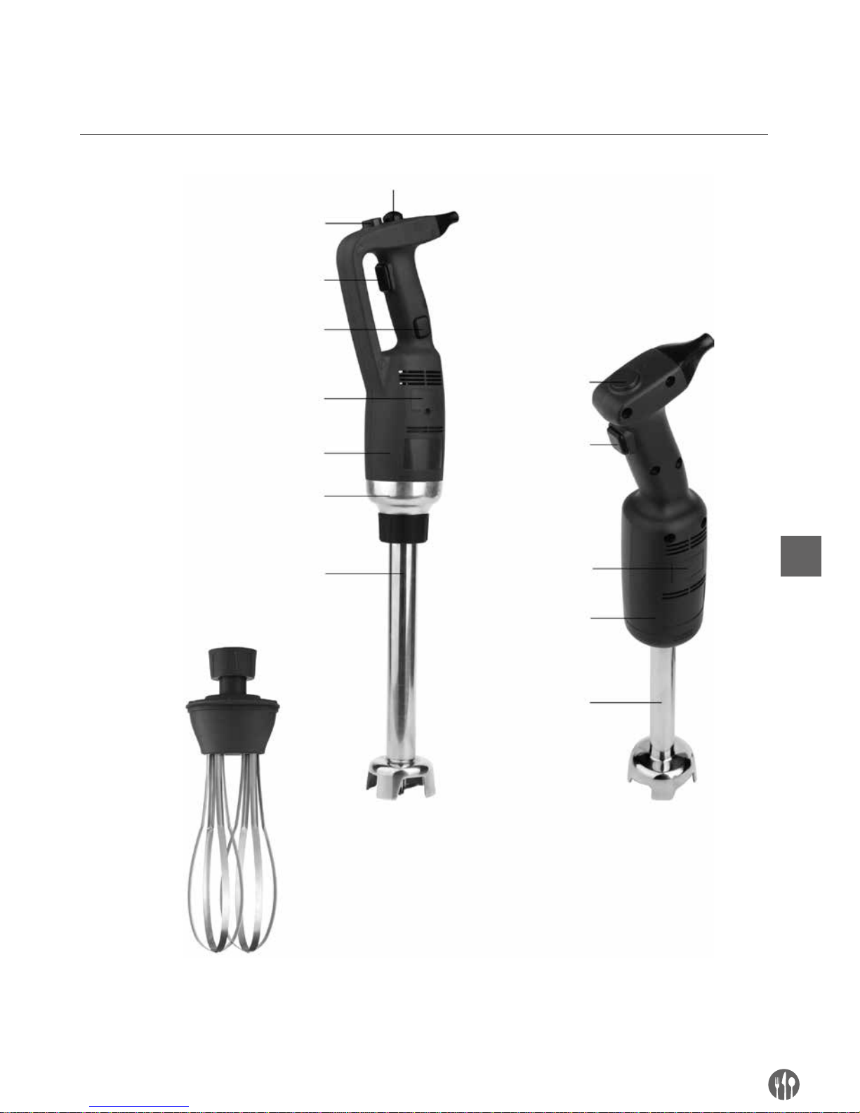
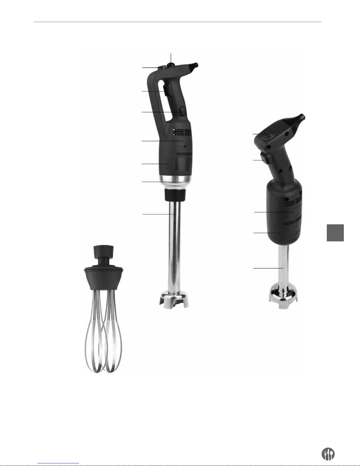
Product description
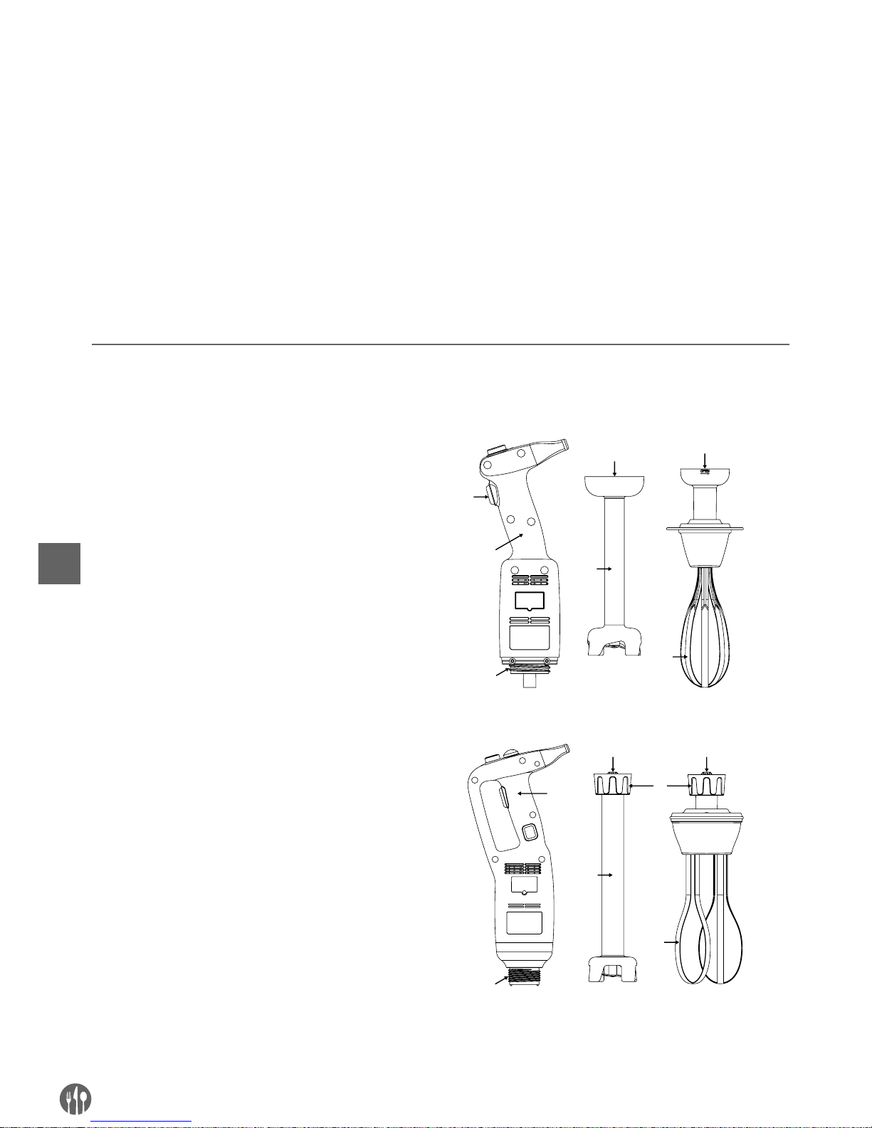
Variable speed
knob (option)
Variable speed
knob
Safety button
On-off button
On-off button
Locking button
Carbon brush cover
Carbon brush cover
Plastic housing
Plastic housing
Coupling
Blender shaft
(not supplied)
Blender shaft
Whisk (only 222133 supplied)
222171 with an additional
blender shaft (not supplied)
222188 with an additional
blender shaft (not supplied)
222133 with 400mm blender shaft
222140
Page 6
6
EN
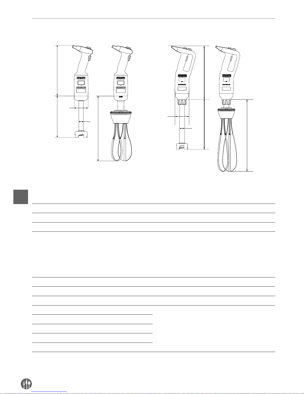
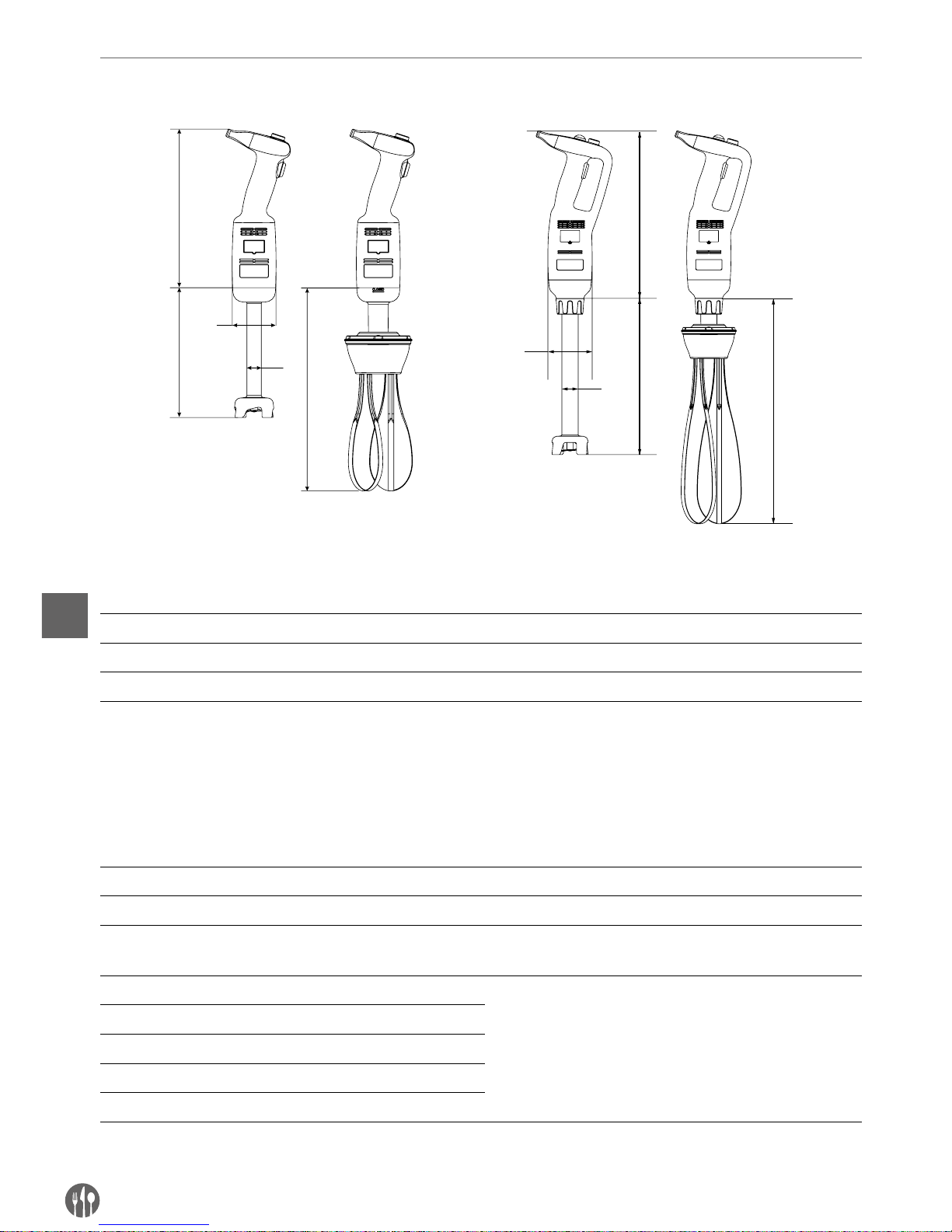
Main technical parameters
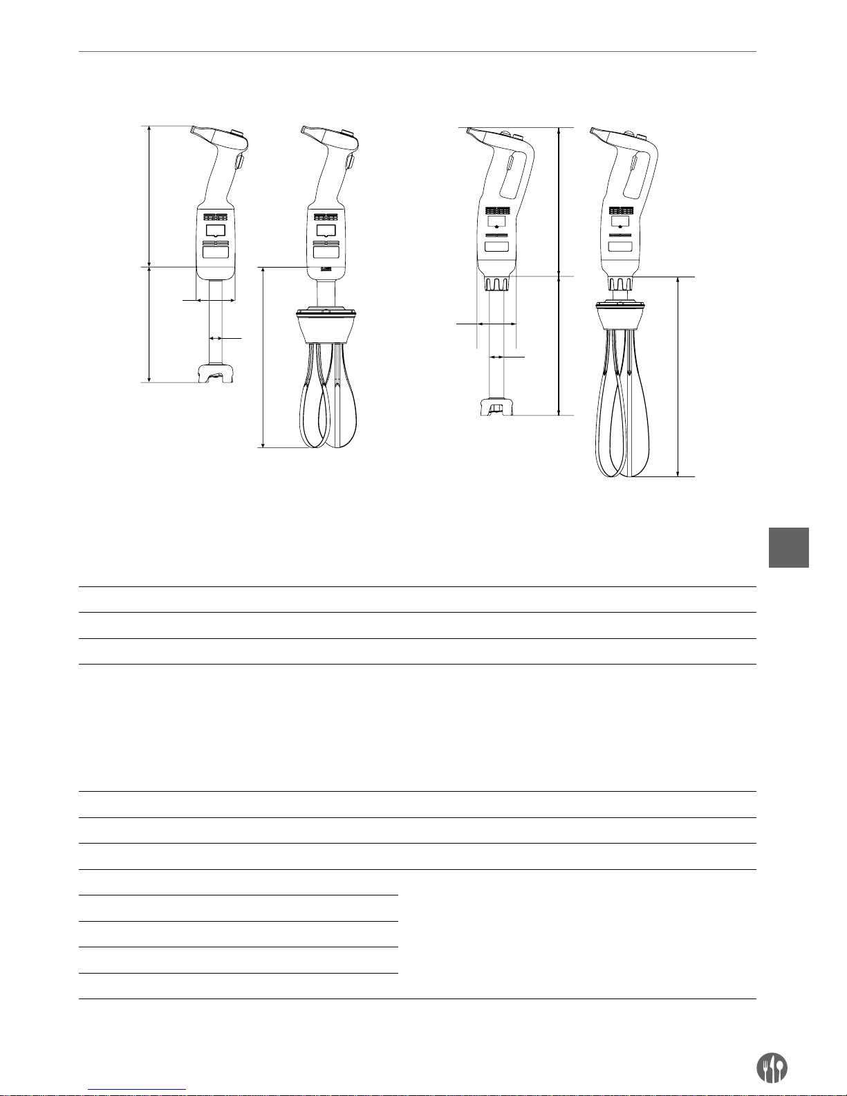
Model: 222140 Model: 222171/222188
A
C
B
D
C
D
B
A
C
C
Technical Specifications
Code Supply
voltage
Power Approx.
rotation speed
Approx. weight of main
unit excluding blending
shaft or whisk
A
(Length)
B
(Diameter)
222140 23 0 V/5 0 Hz 220 W 4,000 ~ 20,000 rpm 1.15 kg 304 mm Ø 75 mm
222171 23 0 V/5 0 Hz 350 W 4,000 ~ 16,000 rpm 1.76 kg 359 mm Ø 91 mm
222188 23 0 V/5 0 Hz 500 W 4,000 ~ 16,000 rpm 1.98 kg 359 mm Ø 91 mm
Remark: Technical specifications are subject to change without prior notice.
Combination table for the Blender shaft and whisk accessories. Below accessories are not included:
Code Weight C
(Length)
D
(Diameter)
Description
222164 0.81 kg 185 mm – Whisk for 222140 (optional)
– 0.46 kg 160 mm Ø 25 mm Blender shaft for 222140 (supplied)
222263 0.86 kg 250 mm – Whisk for model 222171 (optional) and 222188 (optional)
222218 0.69 kg 200 mm Ø 35 mm
Blender shaft for 222171 (optional) and 222188 (optional)
222225 0.82 kg 250 mm Ø 35 mm
222232 1.02 kg 300 mm Ø 35 mm
222249 1.28 kg 400 mm Ø 35 mm
222256 1.56 kg 500 mm Ø 35 mm
Remarks: Set of item 222133 = 222171 + 222249 + 222263 + wall bracket + installation kits (2 sets of mounting
screws, washers and expansion bolts).
Page 7

7
EN
Introduction
•
Read this Operation Manual carefully before using
the appliance. It contains important for your safety as well as operating and maintenance advice.
•
This appliance is for professional use in icecream shops, restaurants, hotel kitchens for preparing ice-cream mixes, vegetable soups, purees,
sauces, stuffing, mayonnaise, tomato paste, pesto, etc.
•
If you wish to make the best use of the stick
blender functions, you must be thoroughly familiar with its performance and operating features.
•
Maintenance requires just a few simple operations that may be performed by the operator.
•
To ensure a long life and minimize operating
costs, follow the instructions given in this manual.
•
The manufacturer has designed the Immersion
Blender to ensure safe operating conditions.Removal of protections installed by the manufacturer will seriously undermine the guaranteed safety
conditions.
•
To ensure safety, comply with the instructions regarding installation and connection of the device
to the power supply.
•
The device must be installed in a work environment free of corrosive agents.
•
The installation area must not be potentially explosive.
•
Use only supplied SPARE PARTS.
•
This Operation Manual is an integral part of the
Immersion Blender and must be kept in a safe
place. The features, information and drawings
published herein are the exclusive property of the
manufacturer.
•
The appliance functions make it possible to prepare in the minimum time the following types
of food: thick vegetable purees, soups, mashed
potatoes, creams, batters, doughs, mayonnaise,
almond pulp, cream cheese etc.
Preparations before bracket mounting on the wall (For item: 222133 only)
Before installation: Check the wall bracket for any damage & the completeness of the installation kits (2 set
of mounting screws, washers and expansion bolts included). DO NOT install if any missing or damage.
Note:
• Consult a qualified contractor or installer for as-
sistance if you are not certain about the structure
of the wall and ensure that the procedure is carried out properly and safely.
• Installation work should be done by qualified
technicians for the reason of safety.
• The distance between the holes of mounting
screws is about 217mm. Make clear the surrounding before installation.
• Important: Before starting bracket mounting on
the wall, make sure you have all the tools, such
as screw driver, electric drills, measuring tape,
marking pencil (All are not included).
• The bracket must be securely anchored on a wall
by attaching two mounting screws with the expansion bolts inserted.
• Be aware of the items such as ducts, electrical
wires and water pipes that hide behind the walls
in your work area. Special care is required during
installation.
Page 8
8
EN
Operating instructions
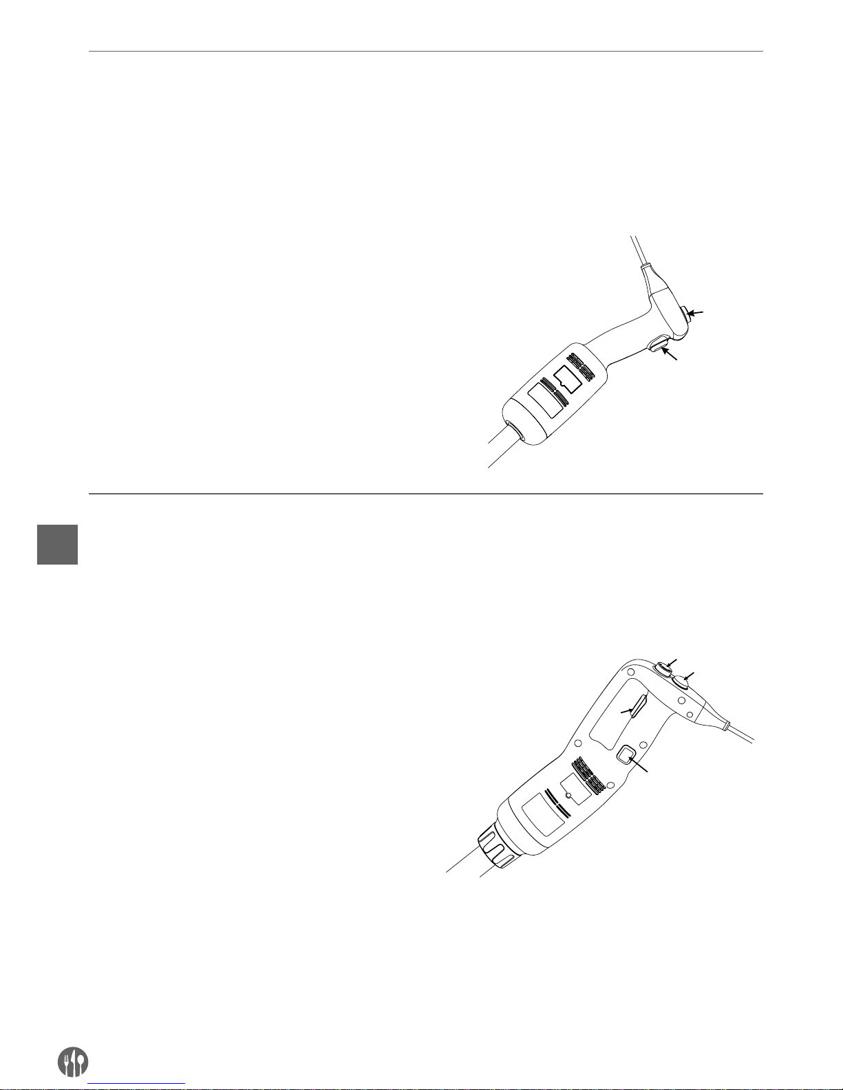
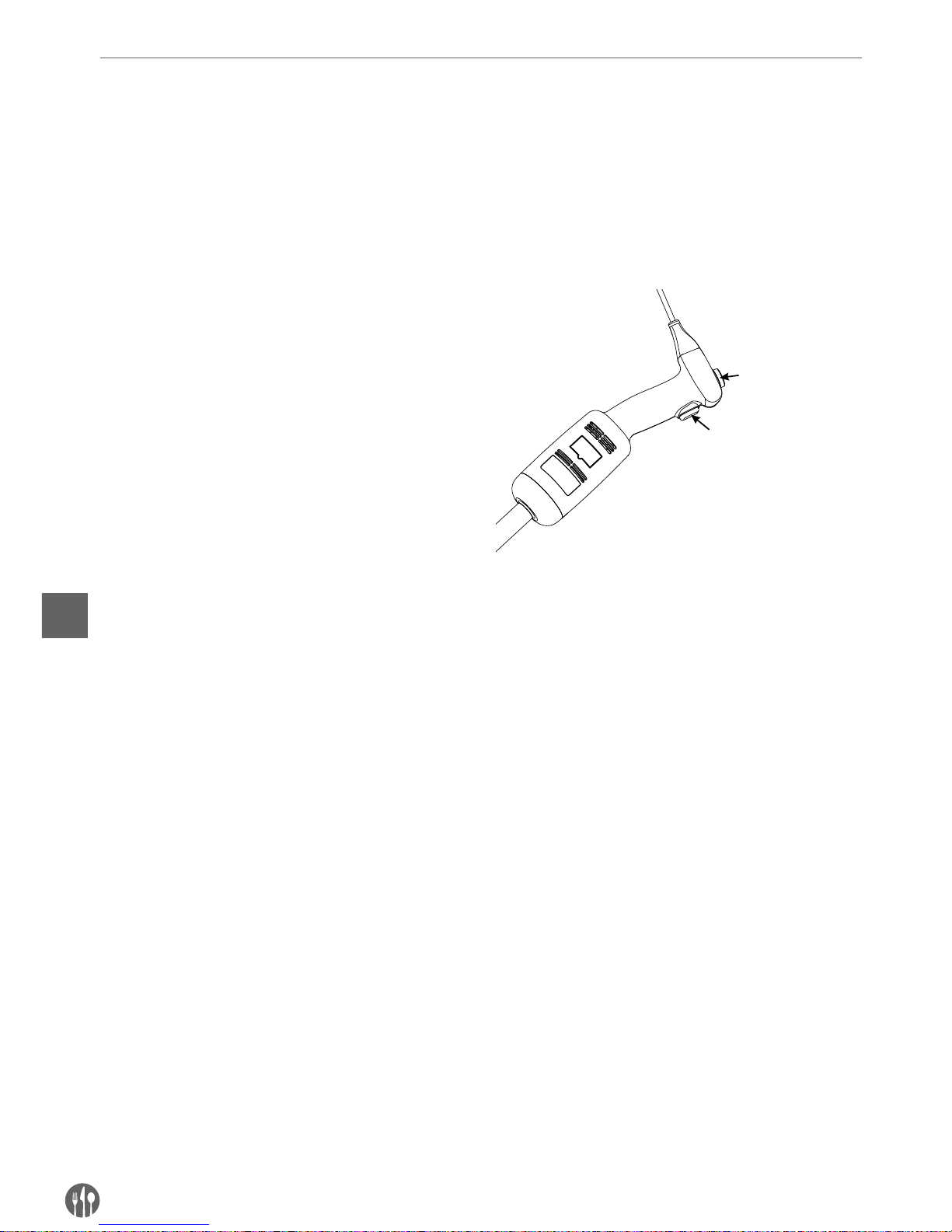
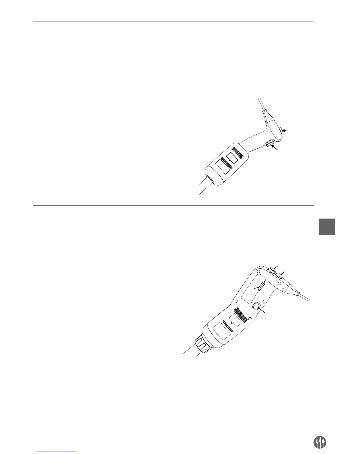
Operating instructions (Model: 222140)
CAUTION: Before connecting the appliance to the power supply, check that the power supply voltage corre-
sponds with the power supply details shown on the rating label.
REMARK: There is no lock function for continuous operation for this model 222140.
Operating the appliance:
1. Ensure that the appliance is disconnected from
the power supply before assembly.
2. Connect the blending shaft/whisk to the main
unit.
3. Connect the appliance to the power supply.
4. Check that the ON/OFF button (1) is in the
released (flat) position.
5. Then, press the ON/OFF button (1). The appliance
will turn on. BE CAREFUL!
6. To turn off the appliance, release the ON/OFF
button (1).
1
2
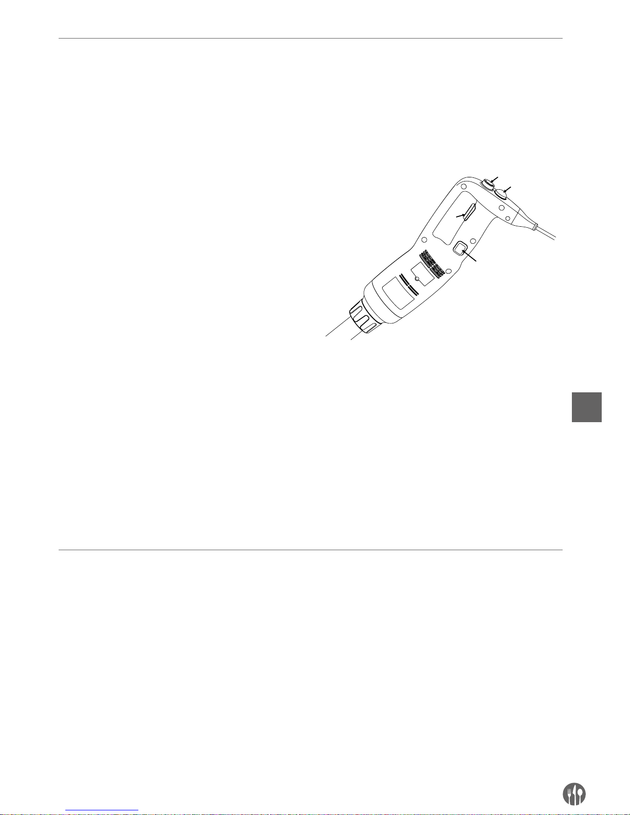
Operating instructions (Model: 222171, 222188 & 222133)
CAUTION: Before connecting the appliance to the power supply, check that the power supply voltage corresponds with the power supply details shown on the rating label.
REMARK: There is lock function for continuous operation for the model 222171 & 222188.
Starting and stopping the appliance
1. Ensure that the appliance is disconnected from
the power supply before assembled.
2. Connect the blending shaft/whisk to the main
unit.
3. Connect the appliance to the power supply.
4. Check that the ON/OFF button (3) is in the
released (flat) position.
5. Press and hold the Enable button (1) first.
6. Then, press the ON/OFF button (3) at the same
time. The appliance will start up. BE CAREFUL!
7. To stop the appliance, release the ON/OFF
button (3) and the Enable button (1).
1
2
3
4
Continuous operating the appliance:
Follow steps 1 to 6 above, then:
•
With the ON/OFF button (3) under “pressed” position & move the finger that press safety button (1)
to the Lock button (4) now.
•
Release the ON/OFF button (3) & the locking but-
ton (4) now, and the appliance will operate in a
continuous mode.
•
To turn off the appliance, press and release the
ON/OFF button (3).
Page 9

9
EN
Variable speed operation (Model: 222140, 222171, 222188 & 222133)
Follow steps 1 to 6 above, then:
• Change the speed of the motor by turning the
variable speed button (2) towards the maximum
or minimum as required. It is advisable to start
the device at a low speed when using the whisk.
With the self-regulating speed system, the selected speed will remain constant even if the
consistency of your mixture changes.
REMARKS:
Blender function: For better control, we recom-
mend you hold the bender by the handle and the
bottom of the motor unit. Furthermore, we recommend you tilt the bender slightly to prevent the bell
from touching the bottom of the container. Always
make sure that the bell is sufficiently immersed to
avoid splashing and that the air vents of the motor
unit do not come into contact with any liquid. For
optimum efficiency, two-thirds of the blending arm
should be immersed in the mixture being prepared.
Whisk function: You can also hold the device with
one hand the bowl with the other hand if necessary. During operation we recommend you move
the whisk around in the bowl in order to ensure
that the mixture is completely homogeneous. Keep
the whisk away from the sides of the bowl. For
maximum efficiency, at least one-fifth of the whisk
length should be immersed. Never immerse the
whisk holder in the mixture.
Page 10
10
EN
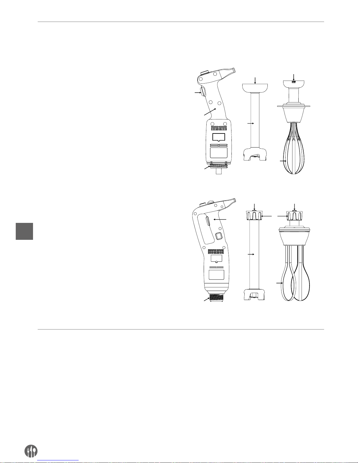
Assembling / Disassembly of the attachments
The assembly / disassembly operations of the appliance are performed with the appliance stopped and disconnected from the power supply.
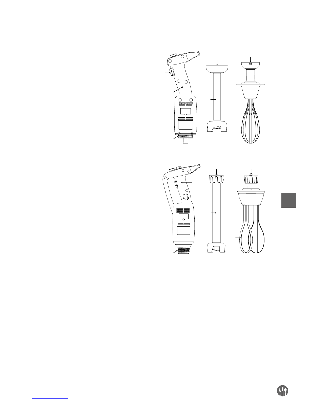
Assembly: Model 222140:
1. Align and insert the coupling (5) of the blending
shaft (3) or the whisk (6) in the clutch (2) of the
main unit (1).
2. Screw thoroughly the blending arm (3) or whisk
(6) to the main unit (1).
Assembly: Model 222171, 222188 and 222133:
1. Align and insert the coupling (5) of the blending
shaft (3) or the whisk (4) in the clutch (2) of the
main unit (1). Make sure the narrower part of the
appliance coupling fits the concave side of the
blender shaft (3) or whisk (4) arm coupling.
2. Screw the nut (6) up to fasten it firmly to the main
unit (1).
4
3
5
2
6
5
4
2
3
1
6
5 5
1
Follow the above steps in the reverse order to disassembly the accessories.
Cleaning instructions
Before cleaning always unplug the appliance form
the source of power supply.
•
After using the Stick Blender in a hot mixture,
cool the blending shaft in cold water before dismantling the bell from the blender shaft. Clean
the shaft immediately after use to prevent adhesion of the mixture.
•
Never immerse the motor unit or the handle in
water; clean with a damp cloth or a sponge.
•
Blender shaft and bell cleaning: Place the blending arm and the bell in a suitable container with
clean water and switch on for a few seconds.
•
WARNING: Always dry the blades thoroughly after
cleaning to avoid rust spotting.
•
Never immerse the whisk holder in water; clean
with a damp cloth or a sponge.
•
After use clean the appliance with a detergent or
disinfectant. Do not use undiluted bleach. Do not
use alkaline detergents to clean plastic parts.
Page 11
11
EN
Troubleshooting
In case of a power cut or if the device has been unplugged, release the ON/OFF button (3), check the
power supply and restart the device.
If the device is switched off due to overheating, release the ON/OFF button (3), and unplug the device, wait a few minutes for the motor to cool down
and the thermal safety mechanism to be reset, and
then restart the device.
If the cause of the problem cannot be determined:
release the ON/OFF button (3), unplug the device,
check below:
1. the plug
2. that the blades are free to rotate in the bell,
3. that state of the power cord,
4. the drive shaft is free to rotate. To this end, remove the bell and test the rotation of the end of
the drive shaft manually.
If a malfunction occurs which is listed in this operation manual, consult your retailer or return the
device to the after-sales service.
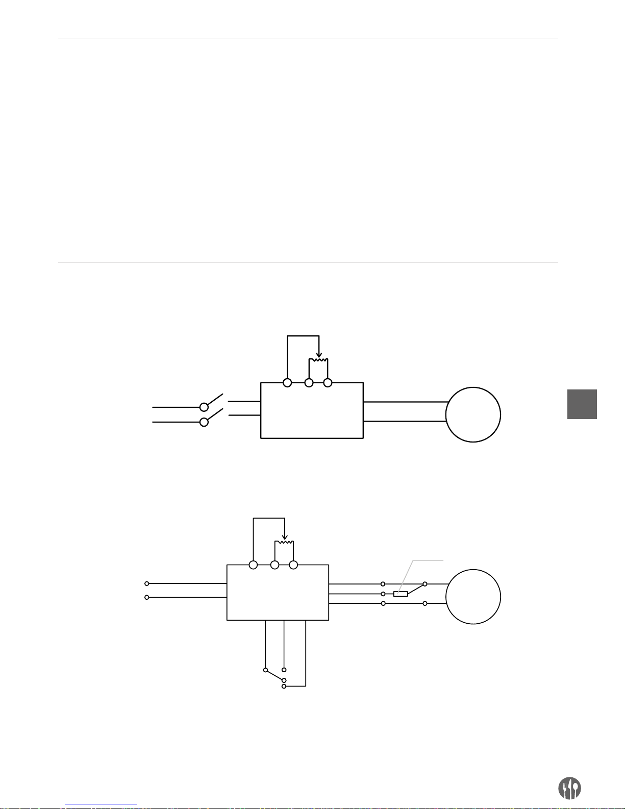
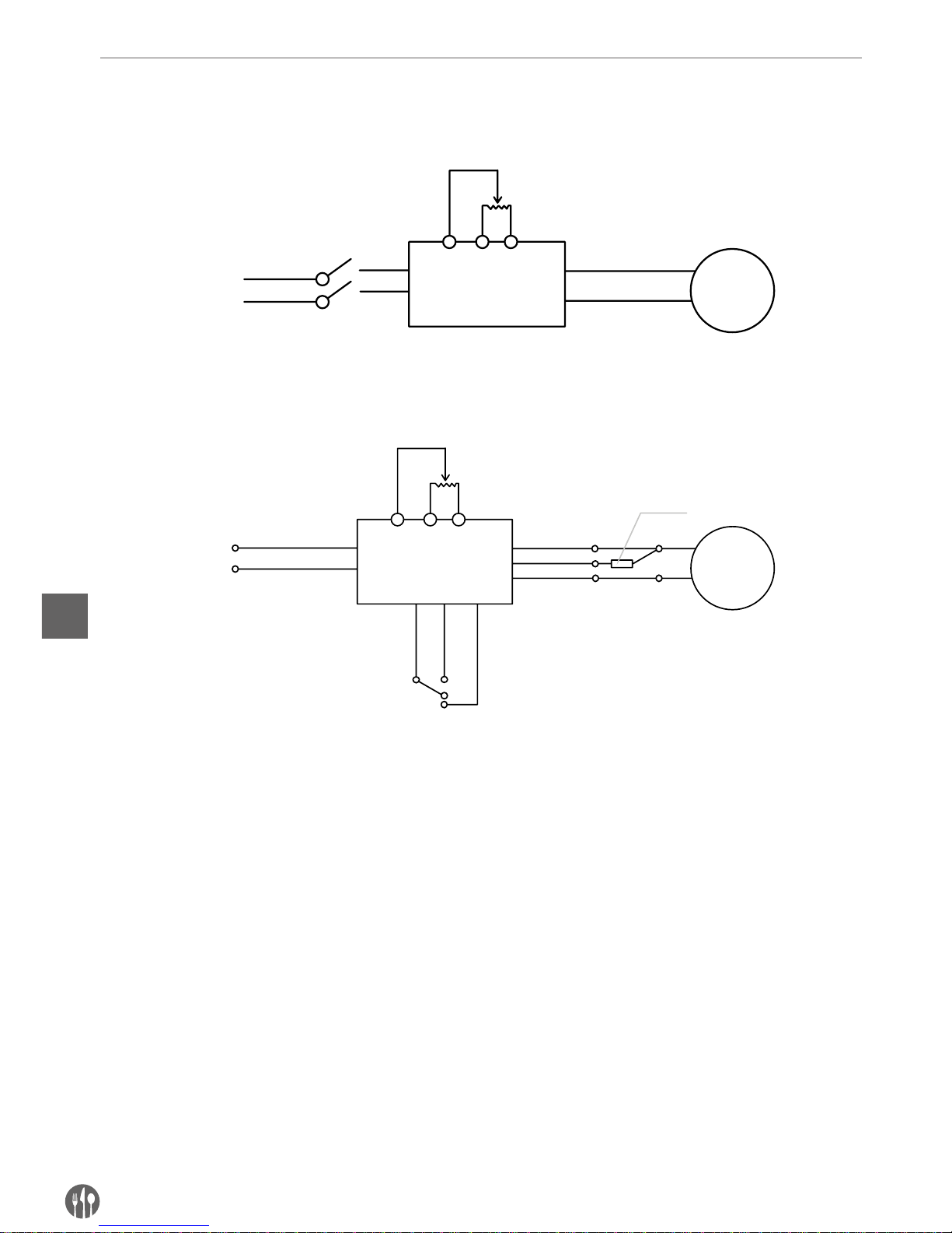
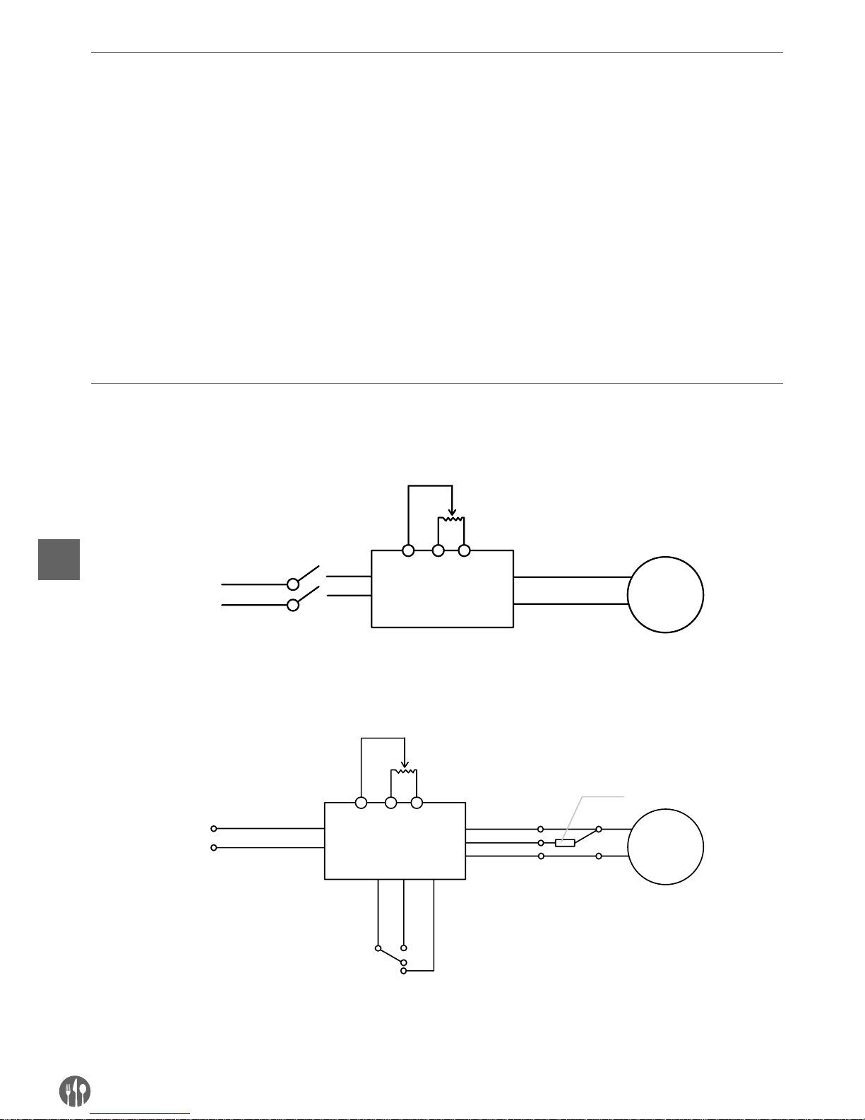
Electrical diagram
Model 222140
AC230V
PC
BM
NO
NO
Variable Resistor
Motor
Switch
Model 222171, 222188 and 222133
AC230V
PCB
M
NOCom
Nc
Variable Resistor
Motor
Switch
Thermal Switch
Page 12
12
EN
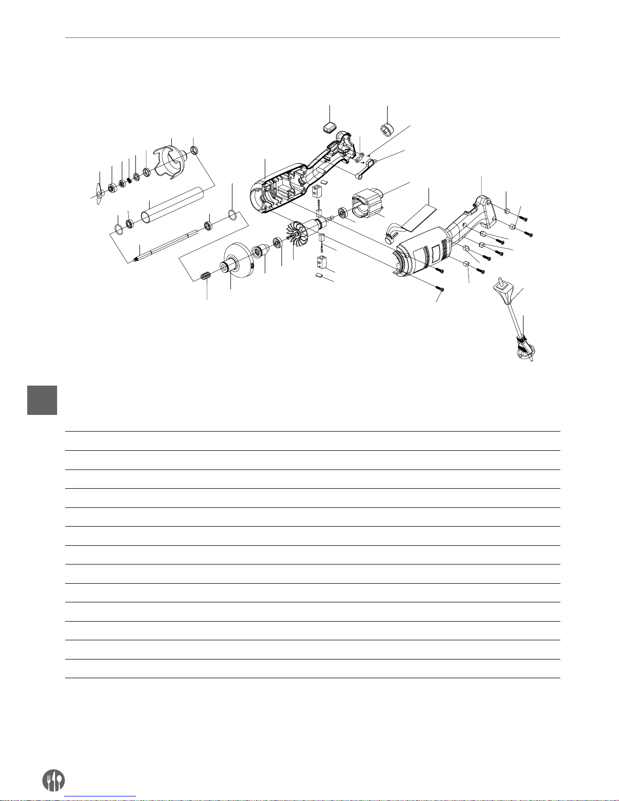
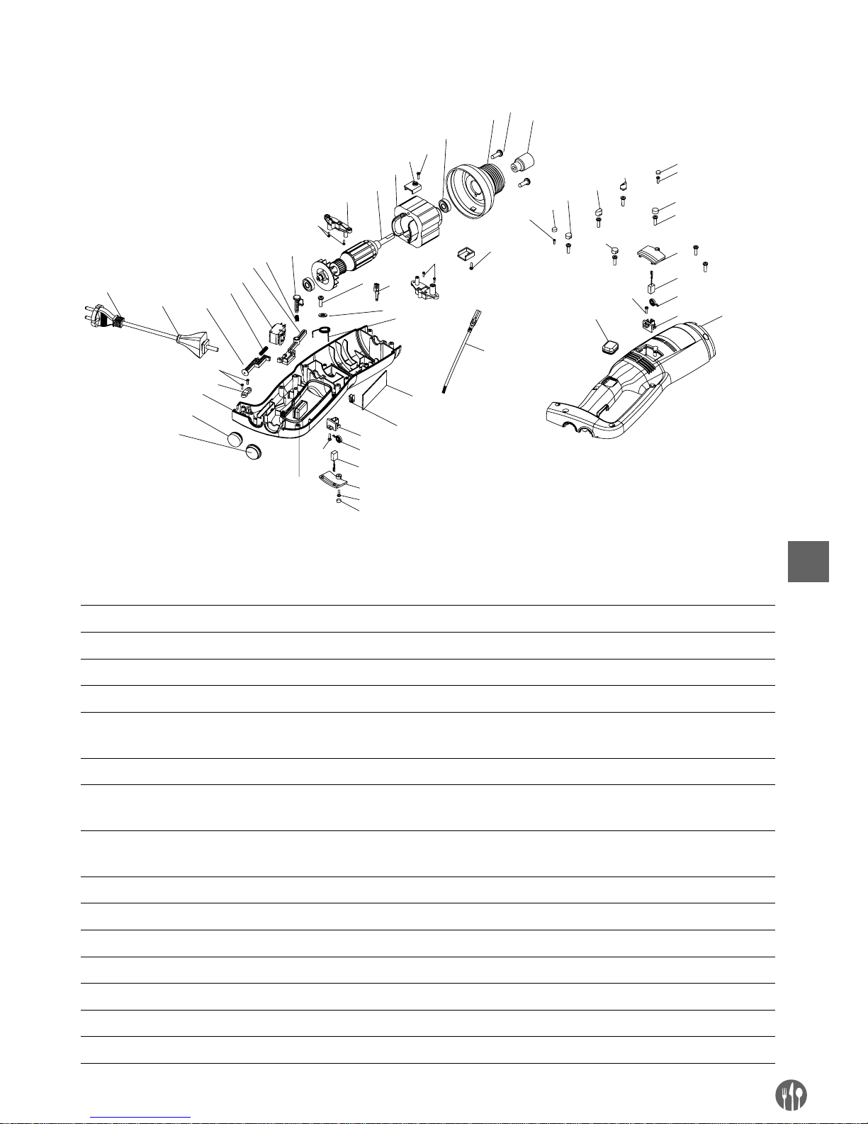
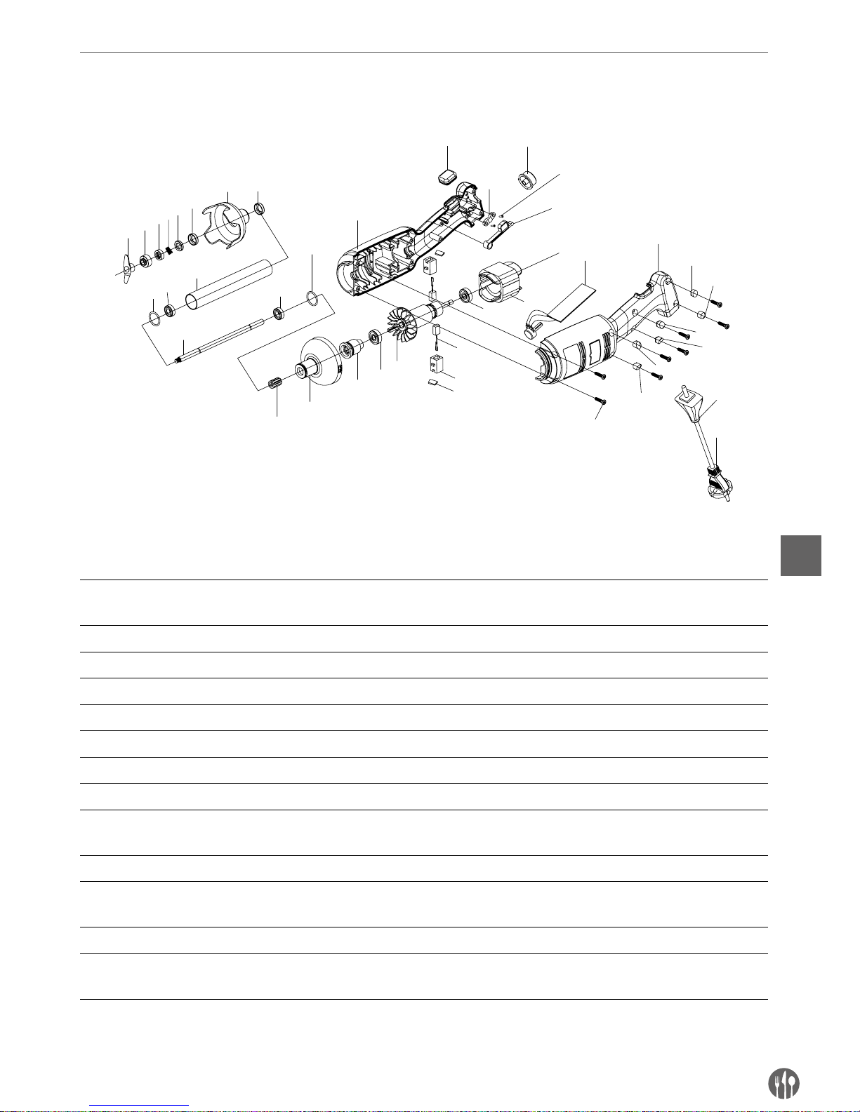
Exploded drawing & part list for model 222140
Model 222140
1
2
4
5
6
7
9
10
11
12
10
9
13
14
15
16
17
19
18
16
20
22
23
25
29-1
31
21
27
24
22
29-2
29-3
29-4
29-5
29-6
30
28
3
26
8
18-1
Part list – model 222140 main unit and blender shaft
Part
No.
Part Name Part
No.
Part Name Part
No.
Part Name
1 Blade 14 Plastic head housing 26 Pressing board screw
2 Convex ring 15 Spline sleeve 27 Switch osculant staff
3 Graphite ring spring 16 Bearing 28 Housing screw
4 Graphite ring 17 Rotor 29-1 Screw plunger 28-1
5 Ceramic ring 18 Brush barrel 29-2 Screw plunger 28-2
6 Ceramic ring sleeve 18-1 Brush cover 29-3 Screw plunger 28-3
7 Knife protector 19 Brush 29-4 Screw plunger 28-4
8 Bearing sleeve 20 Stator 29-5 Screw plunger 28-5
9 Seal ring 21 PCB Speed control board 29-6 Screw plunger 28-6
10 W688Z Bearing 22 Left and right housing 30 Cable sheath
11 S/S tube 23
Rubber interlocking protector
31 Power cord
12 Output axis 24 Pressing board
13 Spline 25 Speed control key
Page 13
13
EN
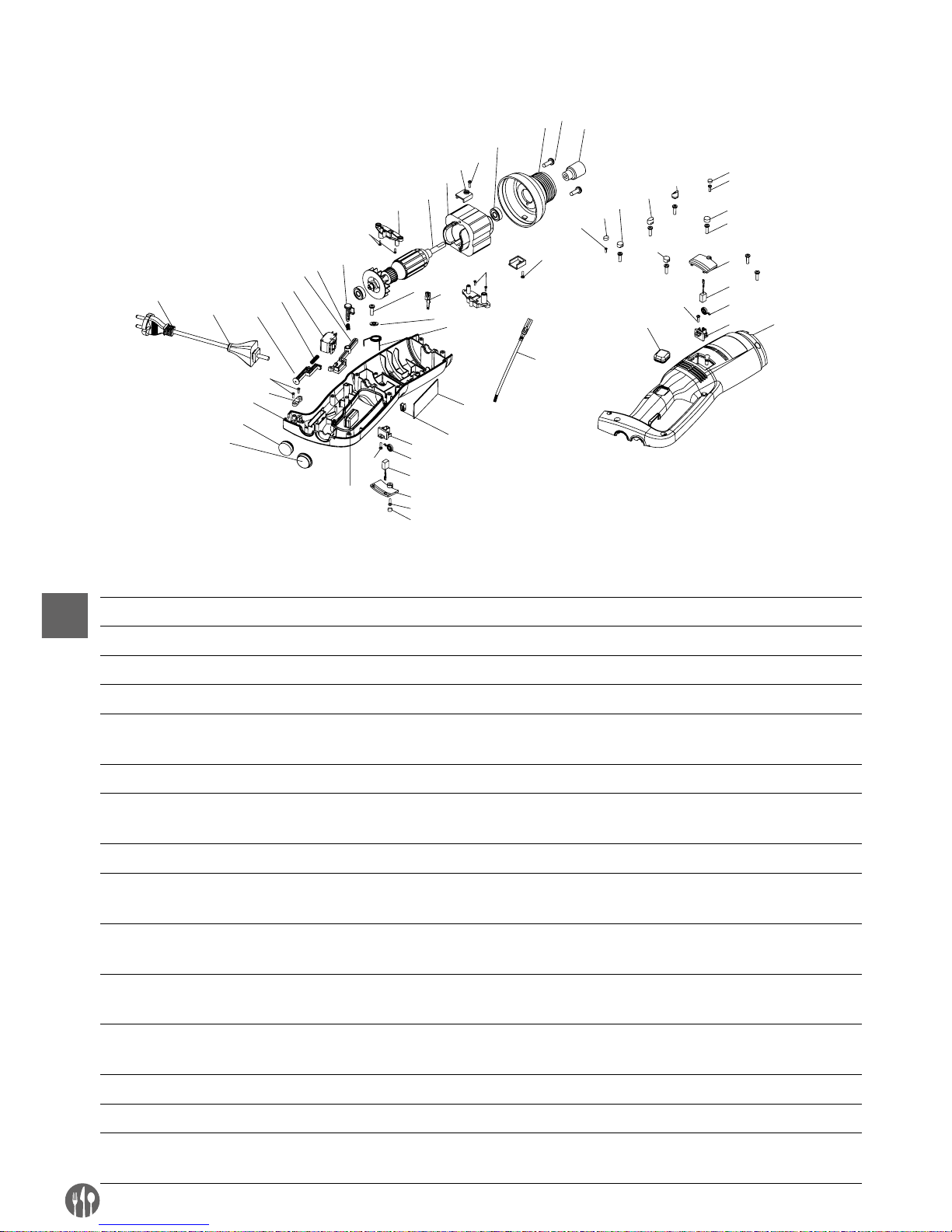
Exploded drawing & part list for model 222171, 222188 & 222133 (Main unit only)
12
13
14
17
18
20
21
23
24
25
26
29
30
31
32
37
5
6
7
8
22
27
33
28
9
4
9
9
2
1-1
28
35
36
34
38
16
15
2
39
1-1
2
4
5
6
7
8
1-3
1-4
1-7
1-5
1-6
3
10
11
19
1-2
9
Part list – model 222171, 222188 & 222133 (main unit only)
Part
No.
Part Name Part
No.
Part Name Part
No.
Part Name
1-1 Screw plunger 1 11 Left housing 26 Cable sheath
1-2 Screw plunger 2 12 Spline sleeve 27 Power cord
1-3 Screw plunger 3 13 Aluminum head 28 Pressing board screw
1-4 Screw plunger 4 14 608 Bearing 29 Pressing board
1-5 Screw plunger 5 15 Motor fixed board
Screw
30 Right housing
1-6 Screw plunger 6 16 Motor fixed board 31 Rubber push sheath
2 3*12 CB Screw 17 IB350W/IB500W Stator
(Depend on different model)
32 Speed control key
3 3*15 CB Screw 18 IB350W/IB500W Stator
(Depend on different model)
33 Switch sheath
4 M4*1 Screw 19 Brush fixed rack 34 Male plug
5 Brush cover 20 Interlocking push bolt 35 Speed control board
6 Brush 21 Interlocking push bolt Spring 36
Switch osculant staff spring
7 3246 Brush cylinder spring 22 Switch osculant staff 37 Speed control board
8 Brush rack 23 Switch 38 Female plug
9 3*12 CB Screw 24 Push bolt spring 39 Lead wire of female plug
10
Rubber interlocking protector
25 Push bolt
Page 14
14
EN
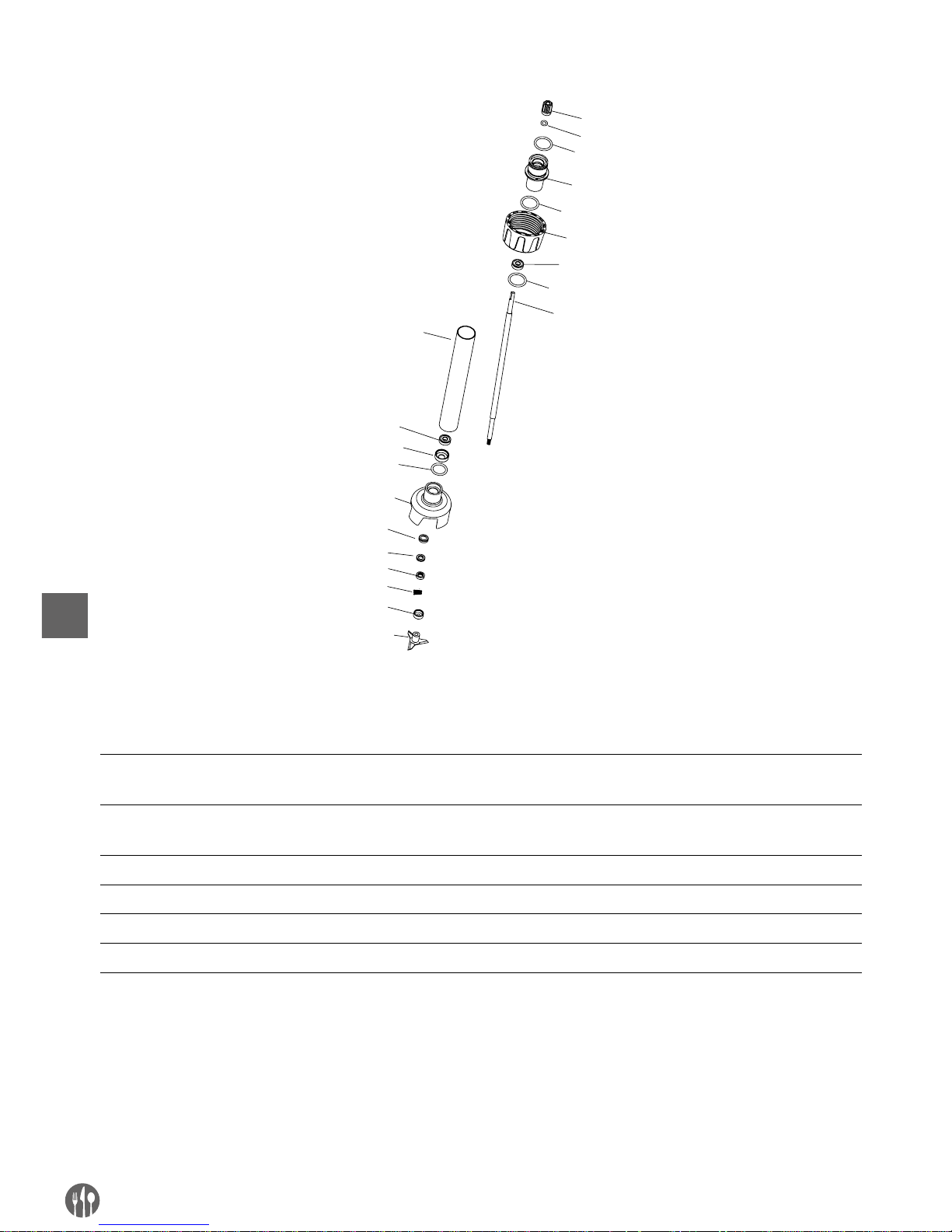
Blender shafts (Optional) for model 222171 & 222188
1
3
6
7
8
6
9
4
10
11
13
15
16
2
5
12
14
4
4
4
Part list – blender shafts (optional): 222218, 222225, 222232, 222249, 222256
Part
No.
Part Name Part
No.
Part Name Part
No.
Part Name
1 Spline sleeve 7 Output axis (Different length
depend on different model)
13 Graphite ring
2 Spline sleeve seal ring 8
304 S/S tube (Different length
depend on different model)
14 Graphite ring spring
3 Connect sleeve 9 Bearing sleeve 15 Convex ring
4 Connect sleeve seal ring 10 Knife protector 16 Blade
5 Fastening sleeve 11 Ceramic ring sleeve
6 608 bearing 12 Ceramic ring
Page 15
15
EN
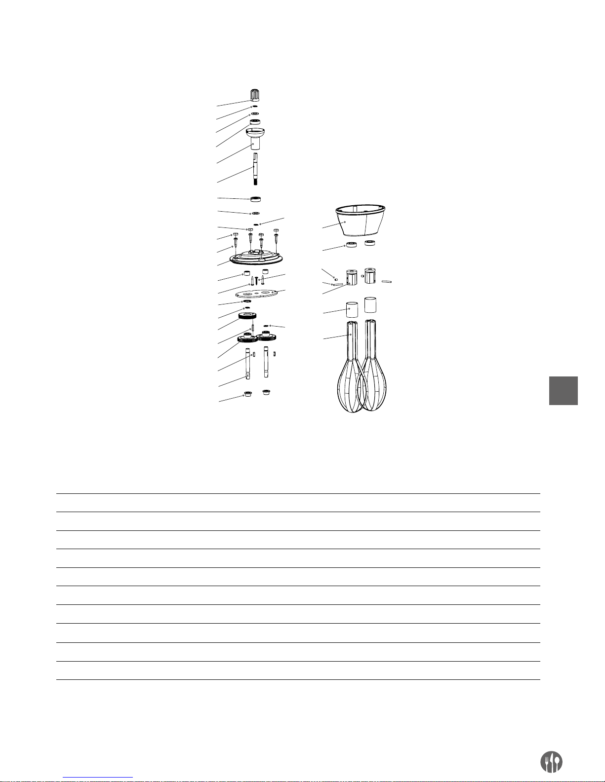
Whisk (Optional) for model 222140
1
2
3
4
5
6
3
4
8
9
11
12
13
2
14
15
16
17
18
19
20
21
22
23
24
25
26
10
7
27
2
28
2
Part list – whisk (optional): model 222164
Part
No.
Part Name Part
No.
Part Name Part
No.
Part Name
1 Spline sleeve 11 Needle bearing 21 Oil sealing
2 Ø8 Snap ring 12 Screw 22 M4x5 Screw
3 Bearing washer 13 Ø16 Snap ring 23 Cylindrical pin
4 Bearing 14 Helical gear bearing 24 Fixed board
5 Connect sleeve 15 Cylindrical pin 25 Steel ring
6 Helical gear bearing 16 Straight gear 26 Steel bar
7 Screw plunger 2 17 Key 27 Baffle plate
8 Screw plunger 1 18 Output axis 28 Screw
9 Housing screw 19 Shaft sleeve
10 Upper cover 20 Lower cover
Page 16
16
EN
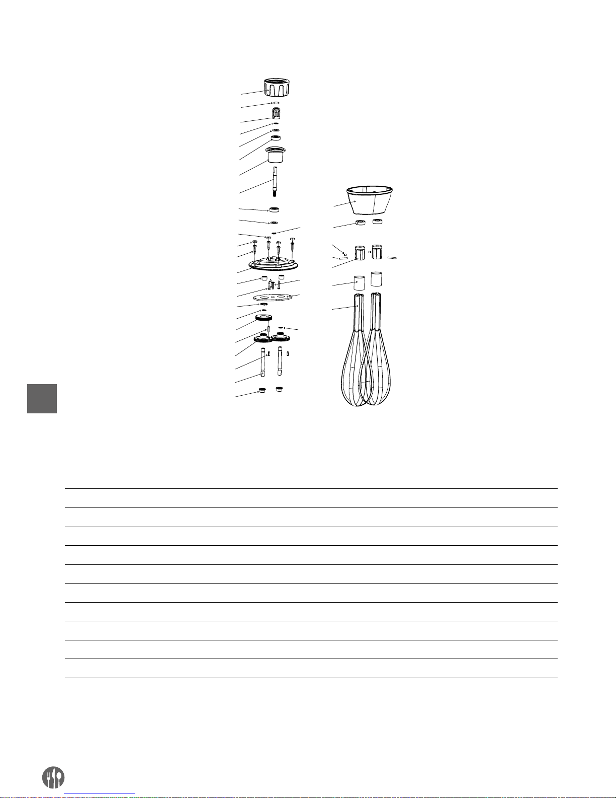
Whisks (Optional) for model 222171 & 222188
3
4
5
6
7
8
5
6
10
11
13
14
15
4
1
6
17
18
19
20
21
22
23
24
25
26
27
28
12
9
29
4
4
30
1
2
Part list – whisk (optional): model 222263
Part
No.
Part Name Part
No.
Part Name Part
No.
Part Name
1 Fastening sleeve 11 Housing screw 21 Shaft sleeve
2 Spline sleeve seal ring 12 Upper cover 22 Lower cover
3 Spline sleeve 13 Needle bearing 23 Oil sealing
4 Ø8 Snap ring 14 Screw 24 M4x5 Screw
5 Oil sealing 15 Ø16 Snap ring 25 Cylindrical pin
6 Bearing 16 Helical gear bearing 26 Fixed board
7 Connect sleeve 17 Cylindrical pin 27 Steel ring
8 Helical gear bearing 18 Straight gear 28 Steel bar
9 Screw plunger 2 19 Key 29 Baffle plate
10 Screw plunger 1 20 Output axis 30 Screw
Page 17

17
EN
Warranty
Any defect affecting the functionality of the appliance which becomes apparent within one year
after purchase will be repaired by free repair or replacement provided the appliance has been used
and maintained in accordance with the instructions
and has not been abused or misused in any way.
Your statutory rights are not affected. If the appliance is claimed under warranty, state where and
when it was purchased and include proof of purchase (e.g. receipt).
In line with our policy of continuous product development we reserve the right to change the product,
packaging and documentation specifications without notice.
Discarding & Environment
At the end of the life of the appliance, please dispose of the appliance according to the regulations
and guidelines applicable at the time.
Throw packing materials like plastic and boxes in
the appropriate containers.
Page 18

18
DE
Sehr geehrte Kundin, sehr geehrter Kunde,
wir danken Ihnen für den Kauf des Gerätes Hendi. Machen Sie sich bitte mit dieser Anleitung noch vor der
Inbetriebnahme des Gerätes vertraut, um Schäden durch die unsachgemäße Bedienung zu vermeiden. Den
Sicherheitsregeln ist besondere Aufmerksamkeit zu widmen.
Sicherheitsregeln
• Die unsachgemäße Bedienung des Geräts kann zur schweren Beschädigung des Geräts
sowie zu Verletzungen führen.
• Das vorliegende Gerät ist ausschließlich für den gewerblichen Gebrauch bestimmt und
darf nicht im Haushalt verwendet werden.
• Das Gerät ist ausschließlich zu dem Zweck zu benutzen, zu dem es hergestellt wurde.
Der Hersteller haftet nicht für Schäden, die auf unsachgemäße Bedienung des Geräts
zurückzuführen sind.
• Den Kontakt des Gerätes und des Steckers mit Wasser oder einer anderen Flüssigkeit
vermeiden. Den Stecker unverzüglich aus dem Stecker ziehen und das Gerät von einem
anerkannten Fachmann prüfen lassen, wenn das Gerät unbeabsichtigterweise ins Was
-
ser fällt. Bei Nichteinhaltung dieser Sicherheitsvorschriften besteht Lebensgefahr.
• Nie eigenständig das Gehäuse des Gerätes zu öffnen versuchen.
• In das Gehäuse des Gerätes keine Gegenstände einführen.
• Den Stecker nicht mit nassen oder feuchten Händen berühren.
• Gefahr eines Stromschlags! Das Gerät darf nicht selbstständig repariert werden. Sämt
liche Mängel und Unzulänglichkeiten sind ausschließlich durch qualifiziertes Personal
zu beseitigen.
• Niemals ein beschädigtes Gerät benutzen! Das beschädigte Gerät vom Netz trennen
und sich mit dem Verkäufer in Verbindung setzen.
• Warnung: Die Elektroteile des Gerätes dürfen weder in Wasser noch in andere Flüssig
keiten getaucht werden. Ebenso ist das Gerät nicht unter fließendes Wasser zu halten.
• Der Stecker und die Stromversorgungsleitung sind regelmäßig auf Beschädigungen zu
prüfen. Der beschädigte Stecker oder Leitung sind an eine Servicestelle oder einer an
deren qualifizierten Person zur Reparatur zu übergeben, um eventuellen Gefahren und
Verletzungen des Körpers vorzubeugen.
• Man muss sich davon überzeugen, ob die Stromversorgungsleitung weder mit scharf
kantigen noch mit heißen Gegenständen in Berührung kommt; halten Sie die Leitung
weit entfernt von einer offenen Flamme. Um den Stecker aus der Netzsteckdose zu neh
men, muss man immer am Stecker und nicht an der Leitung ziehen.
• Die Stromversorgungsleitung (oder Verlängerungsleitung) ist vor dem zufälligen Heraus
ziehen aus der Steckdose zu schützen. Die Stromversorgungsleitung muss so geführt
werden, dass niemand zufällig darüber stolpern kann.
• Das Gerät muss während seiner Anwendung ständig kontrolliert werden.
• Warnung! Wenn der Stecker in der Netzsteckdose ist, muss man das Gerät als an die
Stromversorgung angeschlossen betrachten.
Page 19

19
DE
• Bevor der Stecker aus der Netzsteckdose genommen wird, ist das Gerät auszuschalten.
• Das Gerät darf beim Tragen nicht an der Leitung gehalten werden.
• Benutzen Sie kein Zubehör, das nicht mit diesem Gerät mitgeliefert wurde.
• Das Gerät muss man ausschließlich an die Steckdose mit solch einer Spannung und
Frequenz anschließen, wie auf dem Typenschild angegeben wird.
• Stecken Sie den Stecker in die Steckdose, die an einem leicht und bequem zugänglichen
Ort angeordnet ist, und zwar so, dass das Gerät bei einer Störung sofort abgeschaltet
werden kann. Um das Gerät vollständig auszuschalten, muss man es von der Stromquel
le trennen. Zu diesem Zweck muss man den Stecker, der sich am Ende der vom Gerät
getrennten Leitung befindet, aus der Netzsteckdose ziehen.
• Vor dem Abtrennen des Steckers ist das Gerät auszuschalten!
• Benutzen Sie kein Zubehör, das nicht vom Hersteller empfohlen wird. Die Anwendung
vom nicht empfohlenen Zubehör stellt eine Gefahr für den Nutzer dar und kann zur Be
schädigung des Gerätes führen. Benutzen Sie ausschließlich Ersatzteile und Zubehör im
Original.
• Dieses Gerät eignet sich nicht für den Gebrauch durch Personen (gilt auch für Kinder)
mit geringerer Motorik, Sensorik oder geistiger Fähigkeit oder mangelhafter Erfahrung
und Wissen.
• Auf keinen Fall darf das Bedienen des Gerätes durch Kinder zugelassen werden.
• Das Gerät mit Stromversorgungsleitung ist außerhalb der Reichweite von Kindern zu
lagern.
• Ebenso muss dafür gesorgt werden, dass die Kinder das Gerät nicht zum Spielen benut
-
zen.
• Das Gerät ist immer dann von der Stromversorgung zu trennen, wenn es ohne Aufsicht
bleiben soll bzw. auch vor der Montage, Demontage und Reinigung.
• Während der Nutzung darf das Gerät nicht ohne Aufsicht gelassen werden.
Besondere sicherheitshinweise
• Das Gerät darf nur zum Reiben, Emulgieren sowie Mischen von heißen und kalten Lebensmitteln für kommerzielle Zwecke verwendet werden. Mit dem Gerät kann man Suppen, Püree, Creme, Marzipanmasse, Rahmkäse usw. direkt im Geschirr zubereiten. Die
Verwendung des Geräts für andere Zwecke kann zu seiner Beschädigung oder zu Kör
-
perverletzungen führen.
• Verwenden Sie das Gerät entsprechend den in der Anweisung enthaltenen Hinweisen.
• Das Gerät ist ausschließlich durch ein geschultes Personal in Küchen, Restaurants und
Kantinen oder durch Bedienpersonen an der Bar zu bedienen.
• Wenn das Gerät ohne Aufsicht belassen wird oder vor der Montage, Demontage und Rei
nigung, muss man es unbedingt von der Stromquelle trennen, in dem man den Stecker
aus der Netzsteckdose zieht.
• Während des Betriebes darf man die Schneide nicht auf sich in der Nähe befindende
Personen richten.
Page 20

20
DE
• Während des Funktionsbetriebes darf man weder die Schneide noch die anderen beweglichen Teile berühren. Während des Funktionsbetriebes darf man nicht die beweglichen
Teile mit der Hand als auch mit den anderen Küchengeräten berühren; die Haare zu
-
sammenbinden.
• Das Gerät und sein Zubehör müssen vor dem Anschluss an die Stromquelle und der
Montage des Zubehörs genau getrocknet werden.
• Es besteht die Gefahr von Verletzungen der Hand! Man muss vorsichtig sein – das Mes
-
ser ist scharf.
• Geben Sie während des Funktionsbetriebes keine Zutaten in das Gefäß.
• Warnung: Nach dem Gebrauch und vor dem Abnehmen bzw. Ändern des Zubehörs ist
das Gerät von der Stromversorgung zu trennen.
Um die Halterung (mit Modell 222133 mitgeliefert) an die Wand zu befestigen, machen Sie
sich mit den nachfolgenden Sicherheitshinweisen genau vertraut.
• Für die Sicherheit sollte die Montage durch einen qualifizierten Techniker durchgeführt
werden.
• Überprüfen Sie vor der Montage, dass die Wand das Gewicht des ganzen Geräts und
seines Zubehörs aufnehmen kann.
• Vergewissern Sie sich, dass es in der Nähe des Montageortes keine elektrischen Kabel,
Wasser- und Gasanschlüsse sowie anderen Anlagenelemente gibt.
• Setzen Sie sich mit einer Ausführungsfirma oder einem qualifizierten Spezialisten in
Verbindung, wenn Sie sich der Wandkonstruktion nicht sicher sind.
• Ziehen Sie die Schrauben an. Ziehen Sie die Schraube nicht zu fest an. Ein zu festes An
ziehen der Schrauben kann zu ihrer Beschädigung führen und die Stabilität der Montage
erheblich verringern.
• Während der Montage dürfen sich weder Kinder noch Tiere am Montageort befinden.
• Warnung! Legen Sie auf der Halterung keine Gegenstände als das Gerät, um die Über
ladung der Halterung zu vermeiden.
Page 21
21
DE
Beschreibung des produktes
Stellrad für die variable
Geschwindigkeit (Option)
Taste für
die variable Gesch-
windigkeit (Option)
Sicherheitstaste
Taste Ein/Aus
Taste Ein/Aus
Blockadetaste
Abdeckung der Bürsten
Abdeckung der
Bürsten
Kunststoffgehäuse
Kunststoffgehäuse
Verbindungsstück
Mixstab
(Option)
Mixstab
Schneebesen
(mitgeliefert nur für Modell 222133)
222171 = mit
zusätzlichem Mixstab (Option)
222188 = mit
zusätzlichem Mixstab (Option)
Modell 222133 mit dem Mixstab 400 mm
222140
Page 22
22
DE
Technische hauptparameter
Modell: 222140 Modelle: 222171/222188
A
C
B
D
C
D
B
A
C
C
Technische Spezifikation
Code
Spannung der
Stromversorgung
Leistung Geschätzte
Drehzahl
Geschätztes Gewicht des
Gehäuses ohne Mixstab
oder Schneebesen
A
(Länge)B(Durchmesser)
222140 23 0 V/5 0 Hz 220 W
4 000 ~ 20 000 U/Min.
1,15 kg 304 mm Ø 75 mm
222171 23 0 V/5 0 Hz 350 W
4 000 ~ 16 000 U/Min.
1,76 kg 359 mm Ø 91 mm
222188 23 0 V/5 0 Hz 500 W
4 000 ~ 16 000 U/Min.
1,98 kg 359 mm Ø 91 mm
Achtung: Die technische Spezifikation kann sich ohne Vorankündigung ändern.
Kombinationstabelle mit dem Anschluss des Mixstabes und Schneebesens.
Das angegebene Zubehör wird nicht mit dem Gerät angeliefert.
Code Gewicht C
(Länge)
D
(Durchmesser)
Beschreibung
222164 0,81 kg 185 mm – Schneebesen für Modell 222140 (optional)
– 0,46 kg 160 mm Ø 25 mm Mixstab für Modell 222140 (mitgeliefert)
222263 0,86 kg 250 mm –
Schneebesen für Modelle 222171 (optional)
und 222188 (optional)
222218 0,69 kg 200 mm Ø 35 mm
Mixstab für Modelle 222171 (optional)
und 222188 (optional)
222225 0,82 kg 250 mm Ø 35 mm
222232 1,02 kg 300 mm Ø 35 mm
222249 1,28 kg 400 mm Ø 35 mm
222256 1,56 kg 500 mm Ø 35 mm
Hinweise: Modell 222133 - Satz - umfasst 222171 + 222249 + 222263 + Wandhalterung + Montagesets (2 Sets
der Befestigungsschrauben, Unterlagen und Dübel).
Page 23

23
DE
Einführung
•
Man muss sich mit der vorliegenden Gebrauchsanweisung genau vertraut machen. Sie enthält
wichtige Informationen bezüglich der Sicherheit
des Anwenders sowie die Verwendungs- und
Wartungshinweise.
•
Das Gerät ist für den professionellen Gebrauch in
Eisdielen, Restaurants, Hotelküchen zwecks der
Zubereitung von Eis, Gemüsesuppen, Püree, Soßen, Füllung, Mayonnaise, Tomatenpaste, Pesto,
etc. geeignet.
•
Um die Möglichkeiten des Gerätes komplett zu
nutzen, muss man seine Funktion gut kennen.
•
Die Wartung des Gerätes beruht auf einigen einfachen Tätigkeiten, die vom Bediener ausgeführt
werden können.
•
Um eine lange Betriebszeit bei gleichzeitiger
Senkung der Betriebskosten zu gewährleisten,
muss man die Anweisung beachten.
•
Das Gerät wurde durch den Hersteller so ausgelegt, um auch eine Sicherheit für den Nutzer zu
gewährleisten.
•
Das Abnehmen der durch den Hersteller installierten Sicherheitseinrichtungen senkt erheblich
die Sicherheit bei der Nutzung des Gerätes.
•
Zur Gewährleistung der Sicherheit muss man
auch während der Installation und dem Netzanschluss des Gerätes entsprechend der Anweisung verfahren.
•
Das Gerät ist in einem Arbeitsbereich zu installieren, in dem es keine korrodierenden Faktoren
gibt.
•
Der Installationsbereich darf nicht explosionsgefährdet sein.
•
Es sind ausschließlich die mitgelieferten ERSATZTEILE zu verwenden.
•
Die vorliegende Anweisung ist integraler Bestandteil des Gerätes und man muss sie an einem sicheren Ort aufbewahren. Die in der Anweisung dargestellten Funktionen, Daten und
Abbildungen sind ausschließliches Eigentum des
Herstellers.
•
Die Funktionen des Gerätes ermöglichen die Vorbereitung folgender Arten von Lebensmitteln,
und das in der kürzesten Zeit: dickes Gemüsepüree, Suppen, Kartoffelbrei, Creme, Kuchen,
Mayonnaise, Mandelbrei, cremige Käsearten usw.
Vorbereitungsmaßnahmen vor der Montage der Halterung an der Wand (ausschließlich Modell 222133)
Vor Montage: Überprüfen Sie die Wandhalterung auf Beschädigung und Vollständigkeit der Montagesets (2
Sets der Befestigungsschrauben, Unterlagen und Dübel). Wenn die Wandhalterung beschädigt oder unvollständig ist, MONTIEREN Sie sie NICHT.
Hinweis:
• Setzen Sie sich mit einer qualifizierten Ausführungsfirma oder einem Spezialisten in Verbindung, wenn Sie sich der Wandkonstruktion nicht
sicher sind. Auf diese Art und Weise wird die
richtige und sichere Montage des Geräts sichergestellt.
• Für die Sicherheit sollte die Montage durch qualifizierte Techniker durchgeführt werden.
• Der Abstand der Bohrungen für die Montageschrauben sollte ca. 217 mm betragen. Ordnen
Sie den Montageort vor Beginn der Arbeit.
• Wichtige Informationen: Vor der Montage der
Halterung vergewissern Sie sich, dass alle Werkzeuge wie Schraubenzieher, Elektrobohrmaschine, Messlöffel, Bleistift (nicht mitgeliefert) verfügbar sind.
• Die Halterung ist an die Wand mit Hilfe von zwei
Befestigungsschrauben mit den Dübeln zu befestigen.
• Man muss auch daran denken, dass sich im
Montagebereich auch solche Elemente, wie Kanäle, elektrische Leitungen und Rohre, befinden
können. Während der Montage muss man besonders vorsichtig sein.
Page 24
24
DE
Gebrauchsanweisung
GEBRAUCHSANWEISUNG (MODELL 222140):
ACHTUNG! Bevor das Gerät an die Stromversorgungsquelle angeschlossen wird, muss man überprüfen, ob
die Spezifikation des Gerätes auf dem Typenschild den Parametern in der Steckdose entspricht, an die das
vorliegende Gerät anzuschließen ist.
ACHTUNG! Das Modell 222140 ist nicht mit den Sperrfunktionen für den Dauerbetrieb ausgestattet.
BEDIENUNG DES GERÄTS:
1. Überzeugen Sie sich, ob das Gerät nicht an die
Stromversorgung vor Montage der Teile angeschlossen ist.
2. Schließen Sie den Mixstab / Schneebesen an das
Gehäuse an.
3. Schließen Sie das Gerät an die Stromversorgung
an.
4. Überprüfen Sie, ob die Taste Ein/Aus ausgeschaltet ist (in flacher Stellung).
5. Schalten Sie dann die Taste Ein/Aus. Das Gerät
wird in Betrieb genommen. SEIEN SIE VORSICHTIG!
6. Um das Gerät anzuhalten, muss man die Taste
EIN/AUS freigeben.
1
2
Page 25
25
DE
Gebrauchsanweisung (modelle: 222171, 222188 und 222133)
ACHTUNG! Bevor das Gerät an die Stromversorgungsquelle angeschlossen wird, muss man überprüfen, ob
die Spezifikation des Gerätes auf dem Typenschild den Parametern in der Steckdose entspricht, an die das
vorliegende Gerät anzuschließen ist.
ACHTUNG: Die Modelle 222171 und 222188 sind nicht mit den Sperrfunktionen für den Dauerbetrieb ausgestattet.
INBETRIEBNAHME UND ANHALTEN DES GERÄTS
1. Überzeugen Sie sich, ob das Gerät nicht an die
Stromversorgung vor Montage angeschlossen
ist.
2. Schließen Sie den Mixstab / Schneebesen an das
Gehäuse an.
3. Schließen Sie das Gerät an die Stromversorgung
an.
4. Überprüfen Sie, ob die Taste Ein/Aus (3) ausgeschaltet ist (in flacher Stellung).
5. Schalten Sie zuerst die Sicherheitstaste (1) ein
und drücken Sie sie.
6. Schalten Sie dann die Taste Ein/Aus (3) und drücken Sie sie mit der Sicherheitstaste. Das Gerät
wird in Betrieb genommen. SEIEN SIE VORSICHTIG!
7. Um das Gerät anzuhalten, muss man die Taste
Ein/Aus (3) und die Sicherheitstaste (1) freigeben.
1
2
3
4
DAUERBETRIEB:
Die Schritte 1-6 wie oben ausführen, danach:
•
Bei eingedrückter Taste Ein/Aus (3) verschieben
Sie den Finger von der Sicherheitstaste (1) wird
im Dauerbetrieb arbeiten.auf die Blockadetaste
(4).
•
Geben Sie Taste Ein/Aus (3) und die Sicherheitstaste (4) frei - das Gerät
•
Um das Gerät auszuschalten, muss man die Taste Ein/Aus (3) drücken und freigeben.
Variable geschwindigkeit (modelle: 222140, 222171, 222188 und 222133)
Die Schritte 1-6 wie oben ausführen, danach:
•
Ändern Sie die Geschwindigkeit des Motors, indem Sie das Einstellrad für die Geschwindigkeit
(2) in die Richtung der maximalen oder minimalen Geschwindigkeit verdrehen. Wenn der
Schneebesen verwendet wird, ist zu empfehlen,
dass das Gerät mit einer niedrigen Geschwin-
digkeit in Betrieb genommen wird. Aufgrund des
automatischen Systems der Geschwindigkeitsregelung, bleibt die gewählte Geschwindigkeit konstant, und das sogar in dem Fall, wenn sich die
Konsistenz der gemischten Zutaten verändert.
Page 26
26
DE
ACHTUNG:
Funktion des Mixers: Um eine bessere Kontrolle
zu gewährleisten, empfehlen wir das Festhalten
des Mixers am Haltegriff und am unteren Teil des
Motorgehäuses. Ebenso empfehlen wir, den Mixer
leicht zu kippen, so dass das Ende des Mixstabes
den Boden des Gefäßes nicht berührt. Es ist immer zu prüfen, ob der Mixstab entsprechend tief
genug eingetaucht ist, um Spritzer und das Eindringen der Flüssigkeit in die Lüftungsöffnungen
der Motoreinheit zu verhindern. Für eine optimale
Leistung sollte man zwei Drittel des Mixstabes in
das Gemisch eintauchen.
Funktion des Schlagens: Man kann das Gerät auch
mit einer Hand halten und mit der anderen, falls
notwendig, die Schüssel festhalten. Während des
Schlagens verschiebt man den Schneebesen in der
Schüssel herum, um eine einheitlich geschlagene
Masse zu erhalten. Dabei muss man darauf achten, dass der Schneebesen die Wände der Schüssel nicht berührt. Für eine maximale Leistung
muss man mindestens ein Fünftel der Stablänge
eintauchen. Der Haltegriff darf nicht eingetaucht
werden.
Montage / Demontage
Die Montage/Demontage eines Teiles des Gerätes muss man dann durchführen, wenn das Gerät ausgeschaltet
und von der Stromversorgungsquelle getrennt ist.
Montage: Modell 222140:
1. Das Verbindungsstück (5) des Mixstabes (3) oder
des Schneebesens (6) in das Verbindungsstück
(2) vom Gehäuse des Gerätes (1) anpassen und
stecken.
2. Den Mixstab (3) oder Schneebesen (6) an das Gehäuse (1) genau andrehen.
Montage: Modelle 222171, 22188 und 222133:
1. Das Verbindungsstück (5) des Mixstabes (3) oder
des Schneebesens (4) in das Verbindungsstück
(2) vom Gehäuse des Gerätes (1) anpassen und
stecken. Überzeugen Sie sich, dass die schmalere Seite des Verbinders des Gerätes an die konkave Seite des Verbindungsstückes des Mixstabes (3) oder des Schneebesens (4) angepasst ist.
2. Die Mutter (6) genau an das Gehäuse (1) schrauben.
4
3
5
2
6
5
4
2
3
1
6
5 5
1
Um das Zubehör zu demontieren, muss man die obigen Tätigkeiten in umgekehrter Reihenfolge ausführen.
Page 27

27
DE
Waschanleitung
Vor dem Waschen muss man das Gerät von der
Stromversorgung trennen.
•
Nach dem Gebrauch des Mixers in einer heißen
Mischung waschen; vor Abnahme des Endstücks
vom Mixstab muss man ihn im kalten Wasser
abkühlen. Nach Beendigung der Arbeit ist der
Mixstab sofort zu waschen, um ein Ankleben der
Mischungsreste zu vermeiden.
•
Weder der Motor noch der Haltegriff dürfen in
das Wasser getaucht werden, sie sind mit einem
feuchten Lappen oder Schwamm zu reinigen.
•
Das Reinigen des Mixstabes und des Endstückes:
den Stab und das jeweilige Endstück in ein entsprechendes Gefäß legen, das mit sauberen Wasser gefüllt ist und das Gerät für einige Sekunden
einschalten.
•
WARNUNG: Nach dem Waschen sind die Schneiden genau zu trocknen, damit keine Rostflecke
entstehen.
•
Die Halterung des Schneebesens darf niemals in
das Wasser getaucht werden; sie ist mit einem
feuchten Lappen oder Schwamm zu reinigen.
•
Nach jedem Gebrauch muss man das Gerät mit
einem Reinigungs- oder Desinfektionsmittel
reinigen, dabei darf jedoch niemals ein reines
Bleichmittel verwendet werden. Zum Reinigen
der Kunststoffteile dürfen keine alkalischen Reinigungsmittel benutzt werden.
Problemlösung
Bei einer Unterbrechung der Stromversorgung
oder Abschalten des Gerätes, muss man die Taste
EIN/AUS (3) freigeben, die Stromversorgung überprüfen und das Gerät erneut starten.
Wenn sich das Gerät im Ergebnis einer Überhitzung ausschaltet, ist die Taste EIN/AUS (3) freizugeben, das Gerät von der Stromversorgung zu
trennen, einige Minuten abzuwarten, bis der Motor sich abgekühlt hat und die Sicherung vor dem
Überhitzen zurückgesetzt wird; erst dann ist das
Gerät wieder in Betrieb zu nehmen.
Wenn man die Ursache für das Problem nicht feststellen kann: die Taste EIN/AUS (CB) freigeben,
das Gerät von der Stromversorgung trennen und
das Folgende überprüfen:
1. Stecker,
2. Können sich die Schneiden im Endstück frei drehen?
3. Zustand des Stromkabels,
4. Kann sich die Antriebswelle frei drehen? Zu diesem Zweck muss man das Endstück abnehmen
und manuell prüfen, ob sich das Endstück der
Welle dreht.
Beim Auftreten einer Störung, die nicht in dieser
Anweisung beschrieben ist, muss man sich mit
dem Verkäufer in Verbindung setzen oder das Gerät an einen autorisierten Servicedienst übergeben.
Page 28
28
DE
Elektroschema
Modell 222140
AC230V
PC
BM
NO
NO
Potentiometer
Motor
Schalter
Modell 222171, 222188 und 222133
AC230V
PCB
M
NOCom
Nc
Potentiometer
Motor
Schalter
Thermoschalter
Page 29
29
DE
Explosionszeichnung und teileverzeichnis des modells 222140
Modell 222140
1
2
4
5
6
7
9
10
11
12
10
9
13
14
15
16
17
19
18
16
20
22
23
25
29-1
31
21
27
24
22
29-2
29-3
29-4
29-5
29-6
30
28
3
26
8
18-1
Teileverzeichnis - modell 222140 gehäuse und mixstab
Nr. Bezeichnung des Teiles Nr. Bezeichnung des Teiles Nr. Bezeichnung des Teiles
1 Messer 14 Kunststoffgehäuse des
Kopfstückes
26 Pressing board screw
2 Konkavring 15 Keilhülse 27 Switch osculant staff
3 Graphitringfeder 16 Lager 28 Housing screw
4 Graphitring 17 Rotor 29-1 Screw plunger 28-1
5 Keramikring 18 Halterung für die Bürste 29-2 Screw plunger 28-2
6 Keramikringhülse 18-1 Abdeckung der Bürste 29-3 Screw plunger 28-3
7 Messerabdeckung 19 Bürste 29-4 Screw plunger 28-4
8 Lagerhülse 20 Stator 29-5 Screw plunger 28-5
9 Dichtungsring 21 Platte der Geschwindigkeits
-
steuerung
29-6 Screw plunger 28-6
10 Lager W688Z 22 Gehäuse links und rechts 30 Cable sheath
11 Hülse aus Edelstahl 23
Gummisicherung vor dem
Blockieren
31 Power cord
12 Ausgabehülse 24 Andrückleiste
13 Zapfen 25 Taste der Geschwindigkeits
-
steuerung
Page 30
30
DE
Explosionszeichnung und teileverzeichnis der modelle 222171, 222188
und 222133
(ausschliiesslich gehäuse)
12
13
14
17
18
20
21
23
24
25
26
29
30
31
32
37
5
6
7
8
22
27
33
28
9
4
9
9
2
1-1
28
35
36
34
38
16
15
2
39
1-1
2
4
5
6
7
8
1-3
1-4
1-7
1-5
1-6
3
10
11
19
1-2
9
Teileverzeichnis der modelle 222171 und 222188 (ausschliiesslich gehäuse)
Nr. Bezeichnung des Teiles Nr. Bezeichnung des Teiles Nr. Bezeichnung des Teiles
1-1 Gewindebolzen 1 11 Gehäuse links 26 Kabelabdeckung
1-2 Gewindebolzen 2 12 Keilhülse 27 Stromkabel
1-3 Gewindebolzen 3 13 Alukopfstück 28 Schraube der Andrückleiste
1-4 Gewindebolzen 4 14 608 Lager 29 Andrückleiste
1-5 Gewindebolzen 5 15 Schraube der Befestigungs
-
platte des Motors
30 Gehäuse rechts
1-6 Gewindebolzen 6 16
Befestigungsplatte des Motors
31 Gummitaste
2 Schraube 3*12 CB 17 Stator (modellabhängig) 32 Taste der Geschwindigkeits
-
steuerung
3 Schraube 3*15 CB 18 Rotor (modellabhängig) 33 Buchse des Schalters
4 Schraube M4*1 19 Befestigte Halterung für
die Bürste
34 Stecker (männlich)
5 Abdeckung der Bürste 20 (modellabhängig) 35 Platte der Geschwindigkeits
-
steuerung
6 Bürste 21 Blockadebolzen 36 Feder des tangentialen
Schalterschaftes
7 3246 Feder des Bürstenzylin
-
ders
22 Tangentialer Schaft des
Schalters
37 Platte der Geschwindigkeits
-
steuerung
8 Halterung für die Bürste 23 Schalter 38 Stecker (weiblich)
9 Schraube 3*12 CB 24 Feder des Bolzens 39
Leitung zum (weiblichen) Stecker
10
Gummisicherung vor dem
Blockieren
25 Bolzen
Page 31
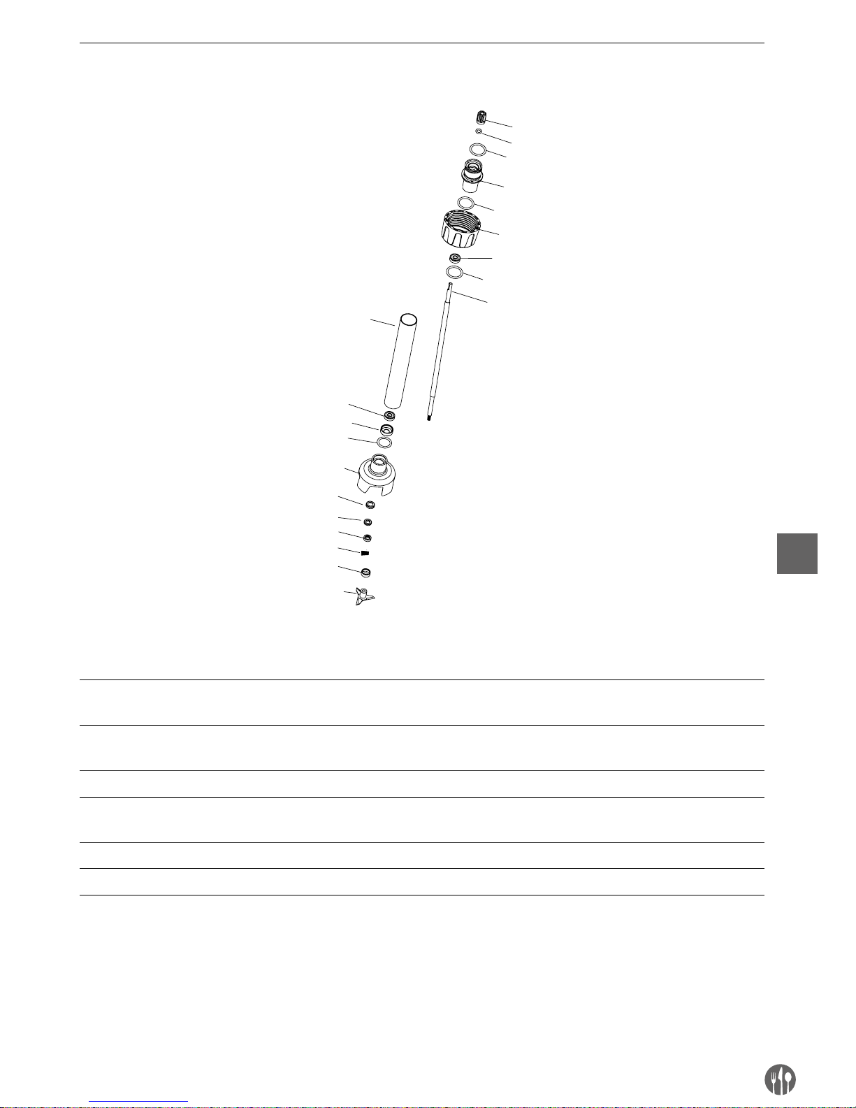
31
DE
Mixstäbe (optional) für modelle 222171, 222188
1
3
6
7
8
6
9
4
10
11
13
15
16
2
5
12
14
4
4
4
Teileliste - mixstäbe (optional): 222218, 222225, 222232, 222249, 222256
Nr. Bezeichnung des Teiles Nr. Bezeichnung des Teiles Nr. Bezeichnung des Teiles
1 Keilhülse 7 Ausgabehülse
(modellabhängig)
13 Graphitring
2 Dichtungsringes
der Keilhülse
8
Hülse aus Edelstahl 304
(modellabhängig)
14 Graphitringfeder
3 Verbindungshülse 9 Lagerhülse 15 Konkavring
4 Dichtungsringes
der Verbindungshülse
10 Messerabdeckung 16 Messer
5 Befestigungshülse 11 Keramikringhülse
6 Lager 608 12 Keramikring
Page 32
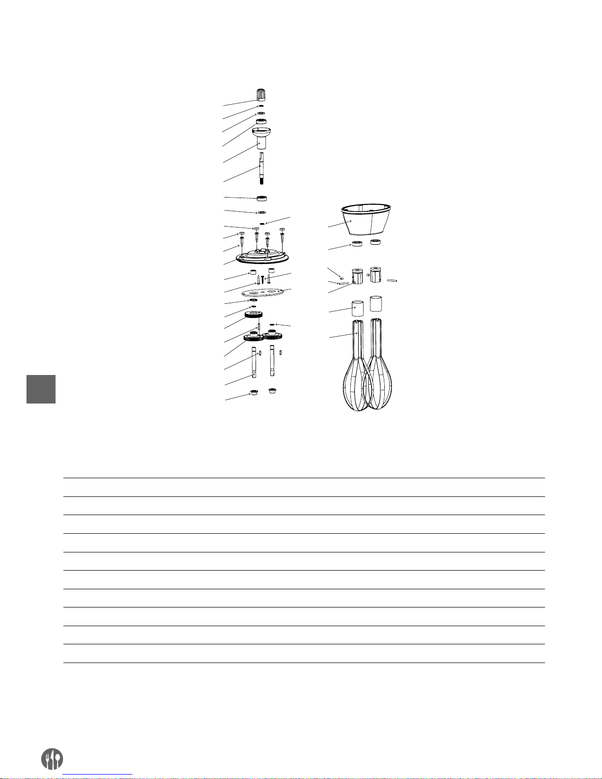
32
DE
Schneebesen (optional) für modelle 222140
1
2
3
4
5
6
3
4
8
9
11
12
13
2
14
15
16
17
18
19
20
21
22
23
24
25
26
10
7
27
2
28
2
Teileliste - mixstab (optional): modell 222164
Nr. Bezeichnung des Teiles Nr. Bezeichnung des Teiles Nr. Bezeichnung des Teiles
1 Keilhülse 11 Nadellager 21 Öldichtung
2 Federring Ø8 12 Schraube 22 Schraube M4x5
3 Dichtung des Lagers 13 Federring Ø16 23 Zylinderstift
4 Lager 14 Lager des Spiralgetriebes 24 Befestigungsleiste
5 Verbindungshülse 15 Zylinderstift 25 Stahlring
6 Lager des Spiralgetriebes 16 Einfaches Getriebe 26 Stahlstab
7 Gewindebolzen 2 17 Taste 27 Prallplatte
8 Gewindebolzen 1 18 Ausgabehülse 28 Schraube
9 Schraube des Gehäuses 19 Stabhülse
10 Obere Abdeckung 20 Untere Abdeckung
Page 33
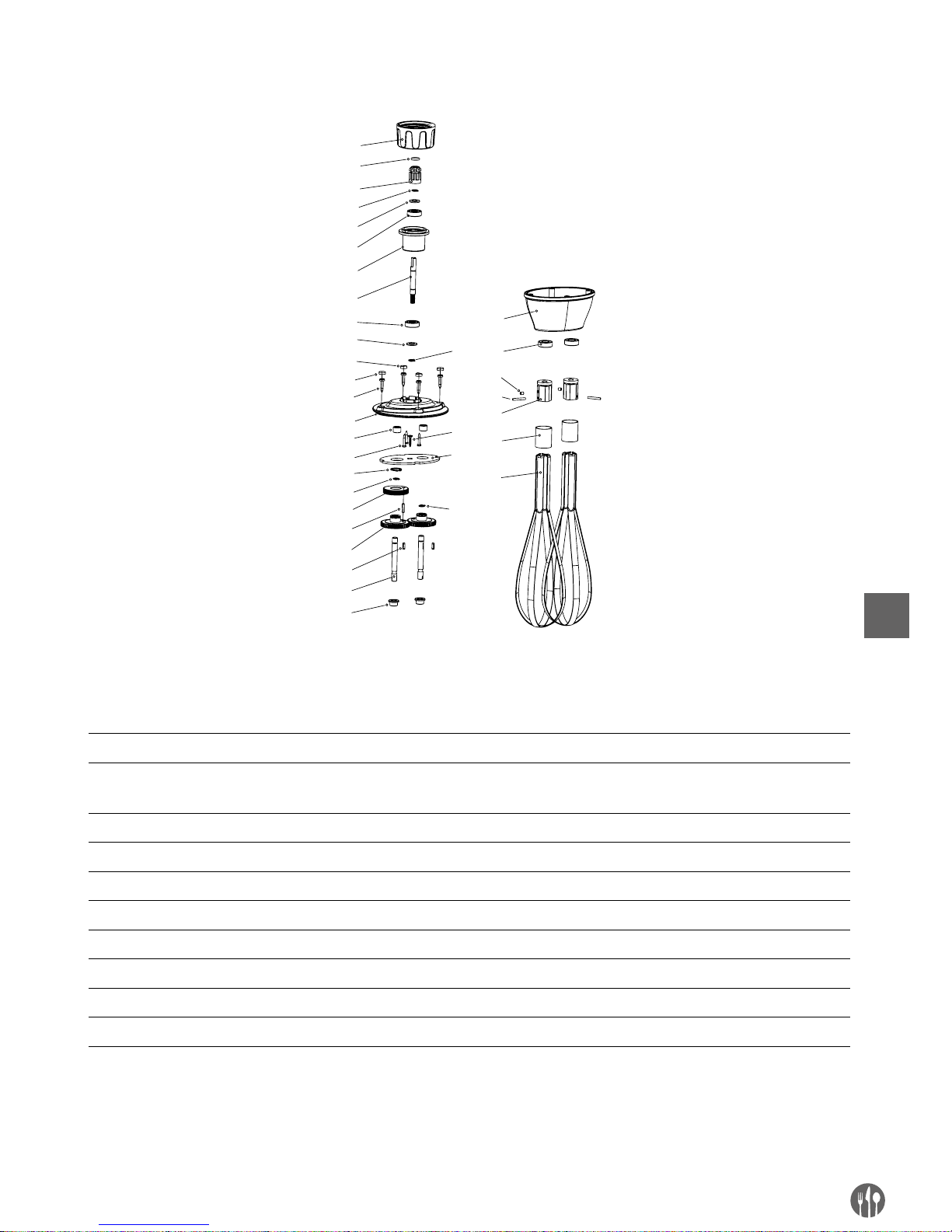
33
DE
Schneebesen (optional) für modelle 222171, 222188
3
4
5
6
7
8
5
6
10
11
13
14
15
4
1
6
17
18
19
20
21
22
23
24
25
26
27
28
12
9
29
4
4
30
1
2
Teileliste - mixstab (optional): modell 222263
Nr. Bezeichnung des Teiles Nr. Bezeichnung des Teiles Nr. Bezeichnung des Teiles
1 Befestigungshülse 11 Schraube des Gehäuses 21 Stabhülse
2 Dichtungsringes
der Keilhülse
12 Obere Abdeckung 22 Untere Abdeckung
3 Keilhülse 13 Nadellager 23 Öldichtung
4 Federring Ø8 14 Schraube 24 Schraube M4x5
5 Öldichtung 15 Federring Ø16 25 Zylinderstift
6 Lager 16 Lager des Spiralgetriebes 26 Befestigungsleiste
7 Verbindungshülse 17 Zylinderstift 27 Stahlring
8 Lager des Spiralgetriebes 18 Einfaches Getriebe 28 Stahlstab
9 Gewindebolzen 2 19 Taste 29 Prallplatte
10 Gewindebolzen 1 20 Ausgabehülse 30 Schraube
Page 34

34
DE
Garantie
Alle innerhalb von einem Jahr nach dem Kaufdatum festgestellten Defekte oder Mängel, die die
Funktionalität des Gerätes beeinträchtigen, werden auf dem Wege der unentgeltlichen Reparatur
bzw. des Austausches unter der Voraussetzung
beseitigt, dass das Gerät in einer der Bedienungsanleitung gemäßen Art und Weise betrieben und
gewartet wird und weder vorsätzlich vernichtet
noch nicht bestimmungsgemäß genutzt wurde.
Ihre Rechte aus den entsprechenden Gesetzen
bleiben davon unberührt. Eine in der Garantiefrist
einzureichende Beanstandung hat die Angabe des
Kaufortes und Kaufdatums und in der Anlage einen
Kaufbeleg (z.B. Kassenzettel) zu enthalten.
Gemäß unserer Politik der ständigen Weiterentwicklung unserer Produkte behalten wir uns vor,
Änderungen am Produkt, an seiner Verpackung
und an den dokumentierten technischen Daten
ohne vorherige Ankündigung vorzunehmen.
Entsorgung und Umweltschutz
Nach Beendigung seiner Lebensdauer ist das Gerät rechtmäßig und den jeweils geltenden Richtlinien entsprechend zu entsorgen.
Verpackungsmaterial, wie Kunststoffe bzw.
Schachteln, in die entsprechenden Behälter geben.
Page 35

35
NL
Geachte klant,
Hartelijk dank voor de aankoop van dit Hendi apparaat. Leest u deze gebruiksaanwijzing zorgvuldig voordat
u het apparaat gebruikt, dit om schade door verkeerd gebruik te voorkomen. Lees vooral de veiligheidsinstructies aandachtig door.
Veiligheidsinstructies
• Onjuiste bediening en verkeerd gebruik van het apparaat kan ernstige schade aan het
apparaat en verwonding van personen tot gevolg hebben.
• Dit apparaat mag alleen worden gebruikt voor commerciële doeleinden en mag niet
worden gebruikt voor huishoudelijk gebruik.
• Het apparaat mag alleen worden gebruikt voor het doel waarvoor het werd ontworpen.
De fabrikant aanvaardt geen enkele aansprakelijkheid voor schade als gevolg van on
-
juiste bediening en verkeerd gebruik.
• Zorg dat het apparaat en de stekker niet met water of een andere vloeistof in aanrak
ing komen. Mocht het apparaat onverhoopt in het water vallen, trek dan onmiddellijk de
stekker uit het stopcontact en laat het apparaat controleren door een erkend vakman.
Niet-naleving hiervan kan levensgevaar opleveren.
• Probeer nooit zelf de behuizing van het apparaat te openen.
• Steek geen voorwerpen in de behuizing van het apparaat.
• Raak de stekker niet met natte of vochtige handen aan.
• Gevaar van elektrische schokken! Probeer het apparaat niet zelf te repareren. In het
geval van storingen, laat reparaties alleen uitvoeren door gekwalificeerd personeel.
• Gebruik nooit een beschadigd apparaat! Als het apparaat is beschadigd, haal de stekker
dan uit het stopcontact en neem contact op met de winkel.
• Waarschuwing! Dompel de elektrische onderdelen van het apparaat niet onder in water
of andere vloeistoffen. Houd het apparaat nooit onder stromend water.
• Controleer de stekker en het netsnoer regelmatig op schade. Als de stekker of het nets
noer is beschadigd, moet het worden vervangen door de technische dienst of een soortgelijk gekwalificeerd persoon om gevaar of letsel te voorkomen.
• Zorg ervoor dat het netsnoer niet in contact komt met scherpe of hete voorwerpen en
houd het uit de buurt van open vuur. Als u de stekker uit het stopcontact wilt halen, trek
dan altijd aan de stekker en niet aan het netsnoer.
• Zorg ervoor dat niemand per ongeluk aan het netsnoer (of verlengsnoer) kan trekken of
kan struikelen over het netsnoer.
• Houd het apparaat in de gaten tijdens gebruik.
• Waarschuwing! Zolang de stekker in het stopcontact zit, is het apparaat aangesloten op
de voedingsbron.
• Schakel het apparaat uit voordat u de stekker uit het stopcontact trekt.
• Draag het apparaat nooit aan het netsnoer.
• Gebruik geen extra hulpmiddelen die niet worden meegeleverd met het apparaat.
• Sluit het apparaat alleen aan op een stopcontact met de spanning en frequentie die is
vermeld op het typeplaatje.
Page 36

36
NL
• Sluit de stekker aan op een stopcontact dat eenvoudig bereikt kan worden, zodat de
stekker in geval van nood onmiddellijk uit het stopcontact kan worden getrokken. Trek de
stekker volledig uit het stopcontact om het apparaat volledig uit te schakelen. Gebruik de
stekker om het apparaat los te koppelen van het lichtnet.
• Schakel het apparaat altijd uit voordat u de stekker uit het stopcontact trekt.
• Gebruik nooit accessoires die niet worden aanbevolen door de fabrikant. Zij kunnen mo
gelijk een veiligheidsrisico vormen voor de gebruiker en kunnen het apparaat mogelijk
beschadigen. Gebruik alleen originele onderdelen en accessoires.
• Dit apparaat is niet geschikt voor gebruik door personen (inclusief kinderen) met een
verminderd fysiek, sensorisch of geestelijk vermogen, of gebrek aan ervaring en kennis.
• Dit apparaat mag onder geen enkele omstandigheid worden gebruikt door kinderen.
• Houd het apparaat en het netsnoer buiten bereik van kinderen.
• Kinderen mogen niet met het apparaat spelen.
• Koppel het apparaat altijd los van het lichtnet als het onbeheerd wordt achtergelaten en
voordat het apparaat wordt gemonteerd, gedemonteerd of gereinigd.
• Laat het apparaat nooit onbeheerd achter tijdens gebruik.
Speciale veiligheidsvoorschriften
• Dit apparaat is uitsluitend bedoeld voor het commercieel pureren, emulgeren en mengen
van warme en koude voedingsmiddelen. Het apparaat kan worden gebruikt om direct in
de pan soep, puree, crème, marsepein, kaascrème, etc. te bereiden. Elk ander gebruik
kan leiden tot schade aan het apparaat of lichamelijk letsel.
• Gebruik het apparaat zoals beschreven in de handleiding.
• Dit apparaat moet worden gebruikt door getraind personeel in keukens van restaurants,
kantines of barpersoneel, etc.
• Koppel het apparaat altijd los van het lichtnet als het onbeheerd wordt achtergelaten en
voordat het apparaat wordt gemonteerd, gedemonteerd of gereinigd.
• Zorg ervoor dat het mes nooit in de richting van personen wijst tijdens het gebruik van
het apparaat.
• Raak het mes en de bewegende onderdelen niet aan. Houd vingers, haar, kleding en ke
-
ukengerei uit de buurt van alle bewegende onderdelen.
• Droog het apparaat en alle accessoires af voordat u de stekker in het stopcontact steekt
en voordat u de accessoires bevestigt.
• Gevaar voor handblessures! Wees zeer voorzichtig met het mes, omdat het erg scherp is.
• Voeg nooit ingrediënten toe aan de container terwijl het apparaat in werking is.
Waarschuwing! Haal de stekker onmiddellijk na gebruik uit het stopcontact, voordat u
accessoires verwijdert of vervangt.
Lees de onderstaande veiligheidswaarschuwingen aandachtig door om de wandbeugel van
artikel 222133 aan de wand te monteren:
• Omwille van veiligheidsredenen moet de installatie worden uitgevoerd door een erkend
technicus.
Page 37

37
NL
• Controleer voorafgaand aan de installatie of de wand het gewicht van het apparaat & de
accessoires veilig kan dragen.
• Zorg ervoor dat er geen elektrische draden, water-, gas- of andere leidingen zitten rond
de plaats van installatie.
• Raadpleeg een erkend aannemer of installateur voor hulp als u twijfelt over de wand
-
constructie.
• Draai de schroeven stevig vast, maar niet te vast. Het te stevig aandraaien kan de schro
-
even beschadigen en de bevestigingskracht van schroeven reduceren.
• Houd huisdieren en kinderen uit de buurt tijdens de installatie.
• Waarschuwing! Plaats uitsluitend het apparaat op de beugel om overbelasting van de
beugel te voorkomen.
Page 38
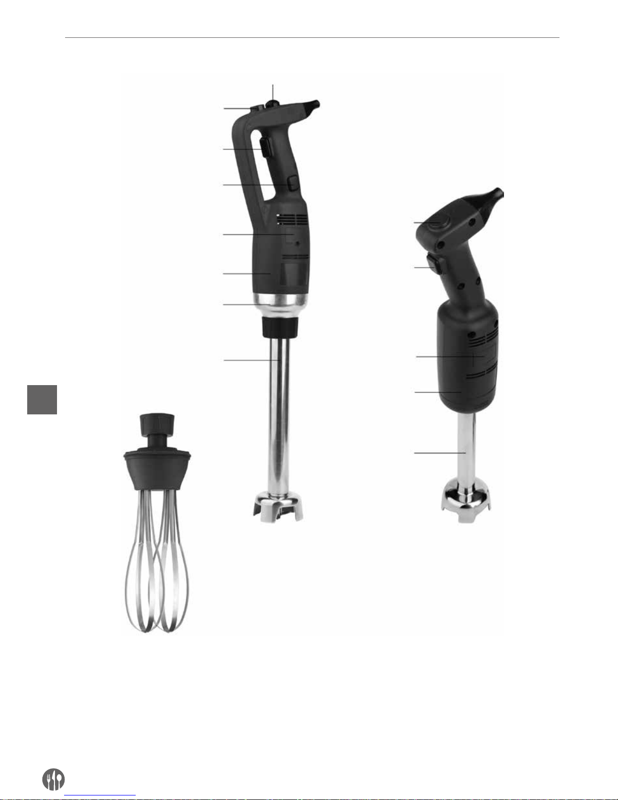
38
NL
Productbeschrijving
Snelheidsregelaar
Snelheidsregelaar
(niet meegeleverd)
Veiligheidsknop
AAN/UIT-knop
AAN/UIT-knop
Vergrendelknop
Deksel koolborstels
Deksel koolborstels
Plastic behuizing
Plastic behuizing
Koppeling
Mixstaaf
(niet meegeleverd)
Mixstaaf
Garde
(alleen 222133 geleverd)
222171 met extra mixstaaf
(niet meegeleverd)
222188 met extra mixstaaf
(niet meegeleverd)
222133 met 400mm mixstaaf
222140
Page 39
39
NL
Belangrijkste technische parameters
A
C
B
D
C
D
B
A
C
C
Technische specificaties
Model Voedings-
-spanning
Vermogen Benadering
rotatiesnelheid
Benadering gewicht van
hoofdapparaat zonder
mixstaaf of garde
A
(Lengte)
B
(Diameter)
222140 23 0 V/5 0 Hz 220 W 4,000 ~ 20,000 rpm 1.15 kg 304 mm Ø 75 mm
222171 23 0 V/5 0 Hz 350 W 4,000 ~ 16,000 rpm 1.76 kg 359 mm Ø 91 mm
222188 23 0 V/5 0 Hz 500 W 4,000 ~ 16,000 rpm 1.98 kg 359 mm Ø 91 mm
Opmerking: Technische specificaties onderhevig aan verandering zonder voorafgaande kennisgeving.
Combinatietabel voor mixstaaf en garde. De onderstaande accessoires worden niet meegeleverd:
Model Gewicht C
(Lengte)
D
(Diameter)
Omschrijving
222164 0.81 kg 185 mm – Garde voor 222140 (optioneel)
– 0.46 kg 160 mm Ø 25 mm Mixstaaf voor 222140 (meegeleverd)
222263 0.86 kg 250 mm – Garde voor model 222171 (optioneel) en 222188 (optioneel)
222218 0.69 kg 200 mm Ø 35 mm
Mixstaaf voor 222171 (optioneel) en 222188 (optioneel)
222225 0.82 kg 250 mm Ø 35 mm
222232 1.02 kg 300 mm Ø 35 mm
222249 1.28 kg 400 mm Ø 35 mm
222256 1.56 kg 500 mm Ø 35 mm
Opmerkingen: Set van artikel 222133 = 222171 + 222249 + 222263 + wandbeugel+ installatiesets (2 sets montageschroeven, sluitringen en expansiebouten).
Model: 222140 Model: 222171/222188
Page 40

40
NL
Inleiding
•
Lees deze handleiding zorgvuldig door voordat u
het apparaat gebruikt. De handleiding bevat belangrijke instructies voor uw veiligheid alsmede
bedienings- en onderhoudsinstructies voor het
apparaat.
•
Dit is apparaat is bedoeld voor professioneel gebruik in ijssalons, restaurants, hotelkeukens voor
het bereiden van ijsmixen, groentesoepen, puree,
sauzen, vullingen, mayonaise, tomatenpuree,
pesto, etc.
•
Als u optimaal gebruik wilt maken van de functies
van de staafmixer, moet u goed op de hoogte zijn
van de prestaties en bediening van het apparaat.
•
Onderhoud vereist slechts een aantal simpele
handelingen die uitgevoerd mogen worden door
de gebruiker.
•
Volg de instructies in deze handleiding om een
lange gebruiksduur te garanderen en de operationele kosten te reduceren.
•
Deze staafmixer is ontworpen om veilige werkomstandigheden te garanderen.
Het verwijderen van beveiligingen die door de
fabrikant zijn aangebracht, zal de gegarandeerde
veilige omstandigheden ernstig in gevaar brengen.
•
Het installeren van het apparaat en de aansluiting
op het lichtnet moet in overeenstemming met de
instructies worden uitgevoerd om de veiligheid te
garanderen.
•
Het apparaat moet in een werkomgeving vrij van
bijtende stoffen worden geïnstalleerd.
•
Installeer het apparaat in een omgeving zonder
potentieel explosiegevaar.
•
Gebruik alleen de meegeleverde reserveonderdelen.
•
Deze handleiding is een integraal onderdeel van
de staafmixer en moet op een veilige plek worden
bewaard. De functies, informatie en tekeningen in
deze handleiding zijn exclusief eigendom van de
fabrikant.
•
De functies van het apparaat maken het mogelijk om de volgende gerechten te bereiden in een
minimale hoeveelheid tijd: dikke groentepuree,
soepen, aardappelpuree, crèmes, beslagen, degen, mayonaise, amandelpulp, roomkaas, etc.
Voorbereidingen voor wandmontage (alleen voor artikel: 222133)
Vóór installatie: Controleer of de wandbeugel niet is beschadigd & controleer of de installatiesets compleet
zijn (2 sets montageschroeven, sluitringen en expansiebouten meegeleverd). Installeer NIET indien er onderdelen ontbreken of beschadigd zijn.
Opmerking:
• Raadpleeg een erkend aannemer of installateur
voor hulp als u twijfelt over de wandconstructie
en zorg ervoor dat de procedure juist en veilig
wordt uitgevoerd.
• Installatiewerkzaamheden moeten omwille van
veiligheidsredenen worden uitgevoerd door een
erkend technicus.
• De afstand tussen de gaten van de montageschroeven is ongeveer 217mm. Maak de omgeving vrij voordat u begint met het installeren.
• Belangrijk: Voordat u start met de installatie
moet u ervoor zorgen dat u over alle benodigde
gereedschappen beschikt. Denk hierbij bijvoor-
beeld aan een schroevendraaier, elektrische
boormachine, meetlint en/of markeerpen (al
deze gereedschappen zijn niet inbegrepen).
• De beugel moet stevig aan een muur worden verankerd door twee montageschroeven te bevestigen met de expansiebouten er ingestoken.
• Houd er rekening mee dat er waterleidingen, elektrische draden en andere leidingen in of achter
de muur kunnen zitten in het werkgebied. Wees
voorzichtig tijdens de installatie.
Page 41
41
NL
Gebruiksaanwijzing
GEBRUIKSAANWIJZING (MODEL: 222140):
LET OP: Controleer voordat u het apparaat aansluit op het lichtnet of de spanning van het lichtnet overeen-
komt met de informatie op het typeplaatje.
OPMERKING: Er is geen vergrendelfunctie voor continu gebruik voor dit model 222140.
HET APPARAAT BEDIENEN:
1. Zorg er vóór de montage voor dat het apparaat is
losgekoppeld van het lichtnet.
2. Sluit de mixstaaf/garde aan op het hoofdapparaat.
3. Sluit het apparaat aan op het lichtnet.
4. Controleer of de AAN/UIT-knop (1) in de niet geactiveerde (platte) stand staat.
5. Druk daarna op de AAN/UIT-knop (1). Het apparaat begint nu in te schakelen. WEES VOORZICHTIG!
6. Schakel het apparaat uit door de AAN/UIT-knop
(1) los te laten.
1
2
Gebruiksaanwijzing (model: 222171 & 222188):
LET OP: Controleer voordat u het apparaat aansluit op het lichtnet of de spanning van het lichtnet overeenkomt met de informatie op het typeplaatje.
OPMERKING: Er is een vergrendelfunctie voor continu gebruik voor de modellen 222171 & 222188.
HET APPARAAT STARTEN EN STOPPEN
1. Zorg er vóór de montage voor dat het apparaat is
losgekoppeld van het lichtnet.
2. Sluit de mixstaaf/garde aan op het hoofdapparaat.
3. Sluit het apparaat aan op het lichtnet.
4. Controleer of de AAN/UIT-knop (3) in de niet geactiveerde (platte) stand staat.
5. Houd eerst de activatieknop (1) ingedrukt.
6. Druk daarna tegelijkertijd op de AAN/UIT-knop
(3). Het apparaat begint nu in te schakelen.
WEES VOORZICHTIG!
7. Stop het apparaat door de AAN/UIT-knop (3) en
de activatieknop (1) los te laten.
1
2
3
4
HET APPARAAT CONTINU GEBRUIKEN:
Volg de stappen 1 tot 6 hierboven en volg daarna de onderstaande stappen:
• Houd de AAN/UIT-knop (3) ingedrukt en verplaats
uw vinger die op de veiligheidsknop (1) drukt nu
naar de vergrendelknop (4).
• Laat de AAN/UIT-knop (3) & de vergrendelknop
(4) los, het apparaat werkt nu in de continue
stand.
• U kunt het apparaat uitschakelen door de AAN/
UIT-knop (3) in te drukken en weer los te laten.
Page 42

42
NL
Bediening met variabele snelheid (model: 222140, 222171 & 222188)
Volg de stappen 1 tot 6 hierboven, daarna:
• Verander de snelheid van de motor door de snelheidsregelaar (2) in de richting van de maximumof minimumsnelheid te draaien. Het wordt aan-
bevolen het apparaat op lage snelheid te starten
wanneer u gebruik maakt van de garde. Met het
zelfregulerende snelheidssysteem zal de gekozen snelheid constant blijven, zelfs als de consistentie van uw mengsel verandert.
OPMERKING:
Gebruik met mixstaaf: Voor betere controle, raden
we aan de blender vast te houden bij het handvat en de onderkant van de motoreenheid. Verder
raden we aan de blender onder een kleine hoek te
kantelen om te voorkomen dat het mixelement van
de staaf in contact komt met de onderkant van de
container. Zorg er altijd voor dat het mixelement
van de staaf voldoende is ondergedompeld om het
opspatten van voedsel te voorkomen en ervoor te
zorgen dat de ventilatieopeningen van de motoreenheid niet in contact komen met vloeistoffen.
Voor een optimaal rendement moet twee derde van
de staaf worden ondergedompeld tijdens het bereiden van voedsel.
Gebruik met garde: U kunt het apparaat met één
hand vasthouden bij het handvat, zodat uw andere
hand vrij is om de kom, indien nodig, vast te houden. Tijdens het bereidingsproces raden we aan de
garde rond te bewegen door de kom om ervoor te
zorgen dat het mengsel volledig homogeen is. We
raden u sterk aan om ervoor te zorgen dat de garde
niet in contact komt met de zijkanten van de kom.
Voor een optimaal rendement moet minimaal een
vijfde van de lengte van de garde worden ondergedompeld. Dompel de gardehouder echter nooit
volledig onder tijdens het bereiden van voedsel.
Page 43
43
NL
MONTAGE / DEMONTAGE VAN HULPSTUKKEN
De montage-/demontagehandelingen van elk onderdeel van het apparaat mogen alleen worden uitgevoerd
als het apparaat is gestopt en losgekoppeld van het lichtnet.
Montage van model 222140:
1. Steek de koppeling (5) van de mixstaaf (3) of garde (6) in de koppeling (2) op het hoofdapparaat
(1).
2. Schroef de mixstaaf (3) of garde (6) omhoog om
deze stevig te vast te zetten in het hoofdapparaat
(1).
Montage van model 222171 en 222188:
1. Steek de koppeling (5) van de staaf (3) of garde (4)
in de koppeling (2) op het hoofdapparaat (1). Zorg
ervoor dat de smallere kant van de koppeling op
het apparaat in de holle kant van de koppeling
van de mixstaaf (3) of garde (4) past.
2. Schroef de moer (6) vast om ze stevig vast te zetten in het hoofdapparaat (1).
4
3
5
2
6
5
4
2
3
1
6
5 5
1
Volg de bovenstaande montagestappen in omgekeerde volgorde om de onderdelen te demonteren.
REINIGINGSINSTRUCTIES
De stekker van het apparaat moet altijd uit het
stopcontact worden gehaald voordat u het apparaat reinigt.
•
Als u de staafmixer heeft gebruikt in een warm
mengsel, koel de mixstaaf dan in koud water
voordat u het mixelement demonteert. Reinig de
staaf onmiddellijk na gebruik om te voorkomen
dat het mengsel vastkleeft op de staaf.
•
Dompel de motoreenheid of de handgreep nooit
onder in water; reinig met een vochtige doek of
spons.
•
Het reinigen van de mixstaaf en het mixelement:
Plaats de mixstaaf en het mixelement in een ges-
chikte container met schoon water en schakel het
apparaat enkele seconden in.
•
WAARSCHUWING: Droog de messen altijd grondig na het reinigen om roest en vlekvorming te
voorkomen.
•
Dompel de gardehouder nooit onder in water,
reinigen het met een licht bevochtigde doek of
spons.
•
Reinig het apparaat na gebruik met een reinigings- of ontsmettingsmiddel. Gebruik geen onverdund bleekmiddel. Gebruik bij het reinigen van
de plastic onderdelen nooit alkalische reinigingsmiddelen.
Page 44
44
NL
Problemen oplossen
In het geval van een stoomstoring of als de stekker van het apparaat uit het stopcontact wordt getrokken, moet u de AAN/UIT-knop (3) loslaten en
de voedingsbron controleren. Start het apparaat
daarna opnieuw.
Als het apparaat door oververhitting is uitgeschakeld, laat de AAN/UIT-knop (3) dan los en
haal de stekker uit het stopcontact. Wacht een paar
minuten om de motor af te laten koelen en ervoor
te zorgen dat het thermische beveiligingsmechanisme kan resetten, start het apparaat daarna opnieuw.
Als u de oorzaak van het probleem niet kunt vinden: laat de AAN/UIT-knop (3) los, haal de stekker
uit het stopcontact en controleer de onderstaande
zaken:
1. de stekker
2. controleer of de messen vrij kunnen roteren in
het mixelement,
3. de staat van het netsnoer,
4. controleer of de aandrijfas vrij kan roteren. Dit
kunt u doen door het mixelement te verwijderen
en de rotatie van het uiteinde van de aandrijfas
handmatig te testen.
Als er een storing optreedt die niet in deze handleiding voorkomt, raadpleeg dan uw dealer of breng
het apparaat terug naar de klantenservice.
Elektrisch schema
Model 222140
AC230V
PC
BM
NO
NO
Variabele weerstand
Motor
Schakelaar
Model 222171 en 222188
AC230V
PCB
M
NOCom
Nc
Variabele weerstand
Motor
Schakelaar
Thermische schakelaar
Page 45
45
NL
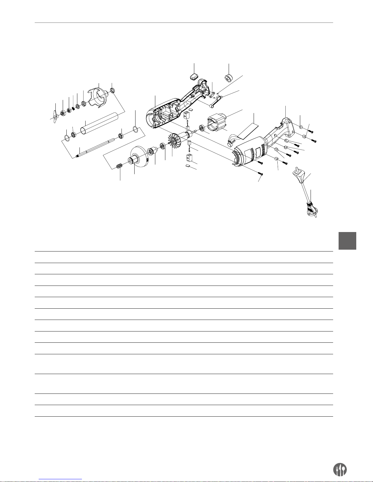
Explosietekening & onderdelenlijst voor model 222140
Model 222140
1
2
4
5
6
7
9
10
11
12
10
9
13
14
15
16
17
19
18
16
20
22
23
25
29-1
31
21
27
24
22
29-2
29-3
29-4
29-5
29-6
30
28
3
26
8
18-1
ONDERDELENLIJST – MODEL 222140 HOOFDAPPARAAT EN MIXSTAAF
Nr. Naam onderdeel Nr. Naam onderdeel Nr. Naam onderdeel
1 Mes 14 Plastic voorkant behuizing 26 Schroef drukplaat
2 Convexring 15 Vertande mof 27 Schakelaar tangentieelstaaf
3 Veer grafietring 16 Lager 28 Schroef behuizing
4 Grafietring 17 Rotor 29-1 Schroefplunjer 28-1
5 Keramische ring 18 Borsteltrommel 29-2 Schroefplunjer 28-2
6 Huls keramische ring 18-1 Deksel borstel 29-3 Schroefplunjer 28-3
7 Mesbeschermer 19 Borstel 29-4 Schroefplunjer 28-4
8 Lagerhuls 20 Stator 29-5 Schroefplunjer 28-5
9 Afdichtingsring 21 Printplaat snelheidsregeling 29-6 Schroefplunjer 28-6
10 W688Z Lager 22 Linker- en rechterkant
behuizing
30 Kabelmantel
11 S/S buis 23
Rubberen vergrendelingsbeschermer
31 Netsnoer
12 Uitvoeras 24 Drukplaat
13 Spiebaan 25 Toets snelheidsregeling
Page 46
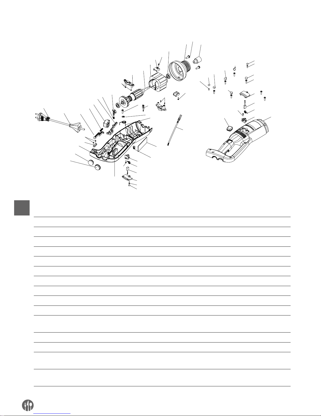
46
NL
EXPLOSIETEKENING & ONDERDELENLIJST VOOR MODEL 222171 & 222188 (ALLEEN HOOFDAPPARAAT)
12
13
14
17
18
20
21
23
24
25
26
29
30
31
32
37
5
6
7
8
22
27
33
28
9
4
9
9
2
1-1
28
35
36
34
38
16
15
2
39
1-1
2
4
5
6
7
8
1-3
1-4
1-7
1-5
1-6
3
10
11
19
1-2
9
ONDERDELENLIJST– MODEL 222171 & 222188 (ALLEEN HOOFDAPPARAAT)
Nr. Naam onderdeel Nr. Naam onderdeel Nr. Naam onderdeel
1-1 Schroefplunjer 1 11 Linkerkant behuizing 26 Kabelmantel
1-2 Schroefplunjer 2 12 Vertande mof 27 Netsnoer
1-3 Schroefplunjer 3 13 Aluminium kop 28 Schroef drukplaat
1-4 Schroefplunjer 4 14 608 Lager 29 Drukplaat
1-5 Schroefplunjer 5 15 Schroef montageplaat motor 30 Rechterkant behuizing
1-6 Schroefplunjer 6 16 Montageplaat motor 31 Rubberen drukmantel
2 3*12 CB Schroef 17
Stator (afhankelijk van model)
32 Toets snelheidsregeling
3 3*15 CB Schroef 18
Rotor (afhankelijk van model)
33 Schakelaar mantel
4 M4*1 Schroef 19 Montagerek borstel 34 Mannelijke stekker
5 Deksel borstel 20 Vergrendeling drukbout 35 Printplaat snelheidsregeling
6 Borstel 21 Vergrendeling veer drukbout 36 Veer schakelaar tangentieel
-
staaf
7 3246 Cilinderveer borstel 22 Schakelaar tangentieelstaaf 37 Printplaat snelheidsregeling
8 Borstelhouder 23 Schakelaar 38 Vrouwelijke stekker
9 3*12 CB Schroef 24 Veer drukbout 39 Voedingsdraad vrouwelijke
stekker
10
Rubberen vergrendelingsbeschermer
25 Drukbout
Page 47
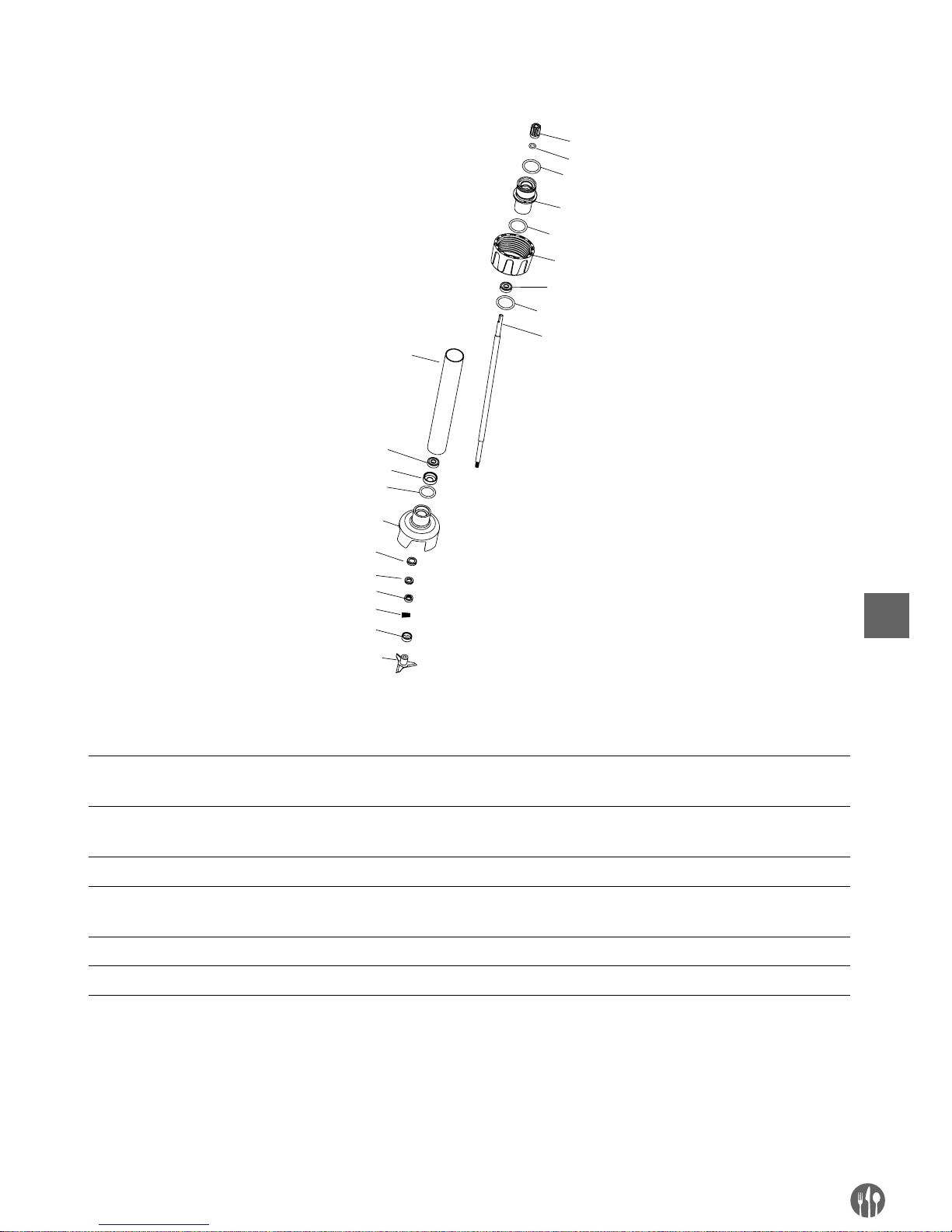
47
NL
MIXSTAVEN (OPTIONEEL) VOOR MODEL 222171, 222188
1
3
6
7
8
6
9
4
10
11
13
15
16
2
5
12
14
4
4
4
ONDERDELENLIJST – MIXSTAVEN (OPTIONEEL): 222218, 222225, 222232, 222249, 222256
Nr. Naam onderdeel Nr. Naam onderdeel Nr. Naam onderdeel
1 Vertande mof 7 Uitvoeras (lengte afhankelijk
van model)
13 Grafietring
2 Afdichtingsring vertande mof 8
304 S/S buis (lengte
afhankelijk van model)
14 Veer grafietring
3 Verbindingshuls 9 Lagerhuls 15 Convexring
4 Afdichtingsring
verbindingshuls
10 Mesbeschermer 16 Mes
5 Bevestigingshuls 11 Huls keramische ring
6 608 lager 12 Keramische ring
Page 48
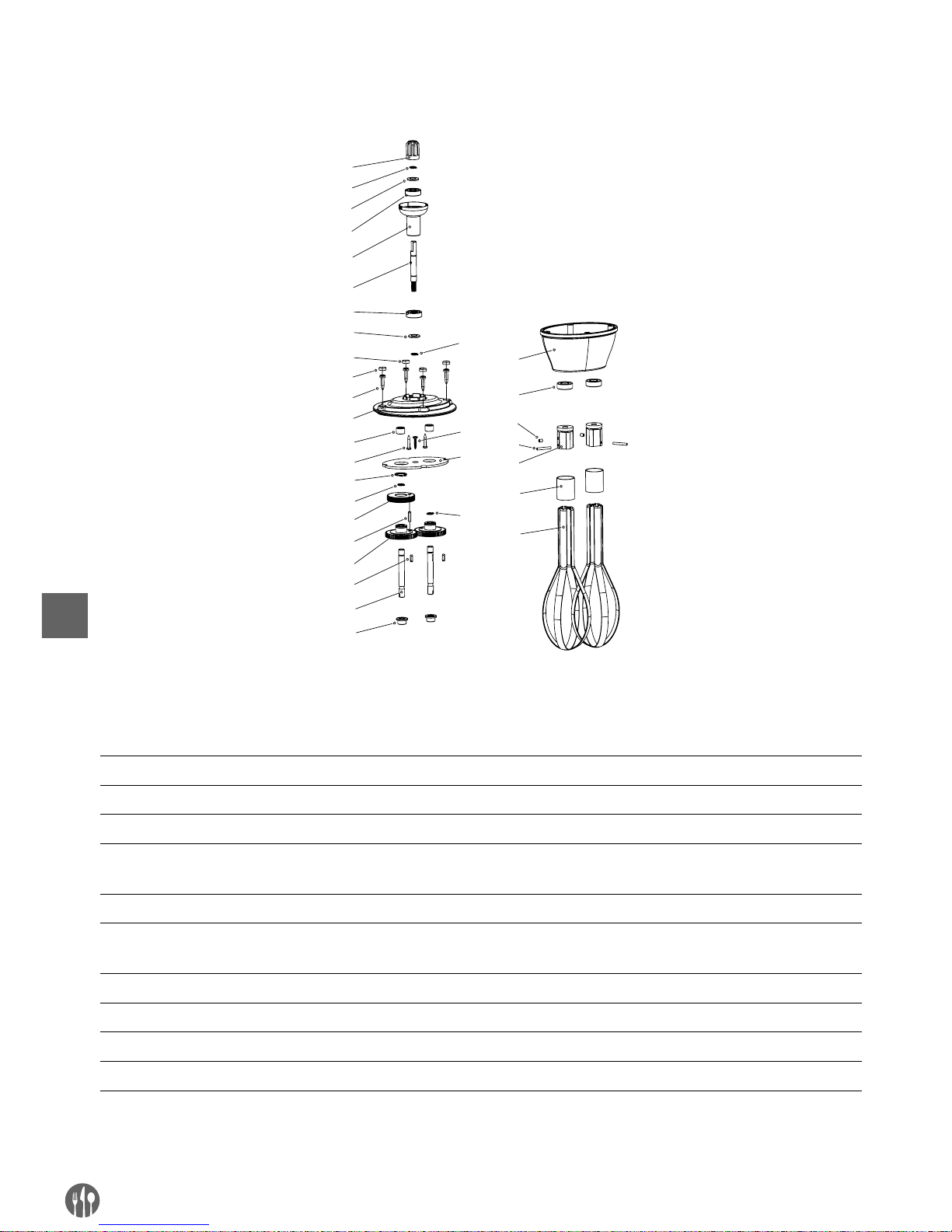
48
NL
GARDE (OPTIONEEL) VOOR MODEL 222140
1
2
3
4
5
6
3
4
8
9
11
12
13
2
14
15
16
17
18
19
20
21
22
23
24
25
26
10
7
27
2
28
2
ONDERDELENLIJST – GARDE (OPTIONEEL): MODEL 222164
Nr. Naam onderdeel Nr. Naam onderdeel Nr. Naam onderdeel
1 Vertande mof 11 Naaldlager 21 Askeerring
2 Φ8 borgring 12 Schroef 22 M4x5 Schroef
3 Sluitring lager 13 Φ16 borgring 23 Cilindrische pen
4 Lager 14 Tandwiel met spiraalvertan
-
ding
24 Montageplaat
5 Verbindingshuls 15 Cilindrische pen 25 Stalen ring
6 Lager tandwiel met
spiraalvertanding
16 Recht tandwiel 26 Stalen balk
7 Schroefplunjer 2 17 Sleutel 27 Keerplaat
8 Schroefplunjer 1 18 Uitvoeras 28 Schroef
9 Schroef behuizing 19 Asbus
10 Bovenkap 20 Onderkap
Page 49
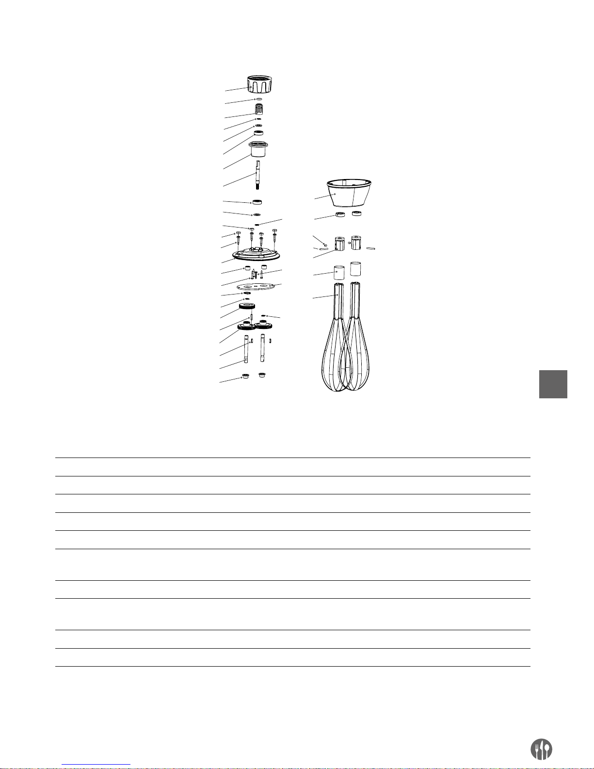
49
NL
GARDES (OPTIONEEL) VOOR MODEL 222171, 222188
3
4
5
6
7
8
5
6
10
11
13
14
15
4
1
6
17
18
19
20
21
22
23
24
25
26
27
28
12
9
29
4
4
30
1
2
ONDERDELENLIJST – GARDE (OPTIONEEL): MODEL 222263
Nr. Naam onderdeel Nr. Naam onderdeel Nr. Naam onderdeel
1 Bevestigingshuls 11 Schroef voor behuizing 21 Asbus
2 Afdichtingsring vertande mof 12 Deksel bovenkant 22 Onderkap
3 Vertande mof 13 Naaldlager 23 Askeerring
4 Φ8 borgring 14 Schroef 24 M4x5 Schroef
5 Askeerring 15 Φ16 borgring 25 Cilindrische pen
6 Lager 16 Lager tandwiel met
spiraalvertanding
26 Montageplaat
7 Verbindingshuls 17 Cilindrische pen 27 Stalen ring
8 Lager tandwiel met
spiraalvertanding
18 Recht tandwiel 28 Stalen balk
9 Schroefplunjer 2 19 Sleutel 29 Keerplaat
10 Schroefplunjer 1 20 Uitvoeras 30 Schroef
Page 50

50
NL
Garantie
Elk defect waardoor de werking van het apparaat nadelig wordt beïnvloed dat zich binnen één
jaar na aankoop van het apparaat voordoet, wordt
gratis hersteld door reparatie of vervanging, mits
het apparaat conform de instructies is gebruikt en
onderhouden en niet op enigerlei wijze verkeerd
is behandeld of misbruikt. Dit laat onverlet uw bij
wet bepaalde rechten. Als de garantie van kracht
is, vermeld dan waar en wanneer u het apparaat
hebt gekocht en sluit een aankoopbewijs bij (bijv.
kassabon of factuur).
Gezien ons streven naar voortdurende verdere productontwikkeling behouden wij ons het recht voor,
zonder voorafgaande kennisgeving wijzigingen aan
te brengen aan product, verpakking en documentatie.
Afdanken & Milieu
Aan het einde van de levensduur, het apparaat afdanken volgens de op dat moment geldende voorschriften en richtlijnen.
Werp verpakkingsmateriaal zoals plastic en dozen
in de daarvoor bestemde containers.
Page 51

51
PL
Szanowny Kliencie,
Dziękujemy za zakup urządzenia firmy Hendi. Prosimy o uważne zapoznanie się z niniejszą instrukcją przed
podłączeniem urządzenia, aby uniknąć uszkodzeń spowodowanych niewłaściwą obsługą. Należy zwrócić
szczególną uwagę na zasady bezpieczeństwa.
Zasady bezpieczeństwa
• Nieprawidłowa obsługa i niewłaściwe użytkowanie mogą spowodować poważne uszkodzenie urządzenia lub zranienie osób.
• Niniejsze urządzenie przeznaczone jest wyłącznie do użytku komercyjnego i nie może być
stosowane do użytku domowego.
• Urządzenie należy stosować wyłącznie zgodnie z przeznaczeniem. Producent nie ponosi
żadnej odpowiedzialności za szkody spowodowane nieprawidłową obsługą i niewłaści
-
wym użytkowaniem urządzenia.
• W czasie użytkowania zabezpiecz urządzenie i wtyczkę kabla zasilającego przed kontak
tem z wodą lub innymi płynami. W mało prawdopodobnym przypadku zanurzenia urządzenia w wodzie, należy natychmiast wyciągnąć wtyczkę z kontaktu, a następnie zlecić
kontrolę urządzenia specjaliście. Nieprzestrzeganie tej instrukcji może spowodować za
grożenie życia.
• Nigdy nie otwieraj samodzielnie obudowy urządzenia.
• Nie wtykaj żadnych przedmiotów w obudowę urządzenia.
• Nie dotykaj wtyczki kabla zasilającego wilgotnymi rękami.
• Niebezpieczeństwo porażenia prądem! Nie należy samodzielnie naprawiać urządzenia.
Wszelkie usterki i niesprawności winny być usuwane wyłącznie przez wykwalifikowany
personel.
• Nigdy nie używać uszkodzonego urządzenia! Uszkodzone urządzenie należy odłączyć od
sieci i skontaktować się ze sprzedawcą.
• Ostrzeżenie: Nie zanurzać części elektrycznych urządzenia w wodzie ani w innych pły
nach. Nie wkładać urządzenia pod bieżącą wodę.
• Regularnie sprawdzać wtyczkę i sznur zasilający pod kątem uszkodzeń. Uszkodzoną
wtyczkę lub sznur przekazać w celu naprawy do punktu serwisowego lub innej wykwalifi
-
kowanej osoby, aby zapobiec ewentualnym zagrożeniom i obrażeniom ciała.
• Upewnić się, czy sznur zasilający nie styka się z ostrymi ani gorącymi przedmiotami; trzy
mać sznur z dala od otwartego płomienia. Aby wyjąć wtyczkę z gniazdka, zawsze ciągnąć
za wtyczkę, a nie za sznur.
• Zabezpieczyć sznur zasilający (lub przedłużający) przez przypadkowym wyciągnięciem z
kontaktu. Sznur prowadzić w sposób uniemożliwiający przypadkowe potknięcie.
• Stale nadzorować urządzenie podczas użytkowania.
• Ostrzeżenie! Jeżeli wtyczka jest włożona do gniazdka, urządzenie należy uważać za pod
-
łączone do zasilania.
• Przed wyjęciem wtyczki z gniazdka wyłączyć urządzenie!
• Nigdy nie przenosić urządzenia, trzymając za sznur.
Page 52

52
PL
• Nie używać żadnych akcesoriów, które nie zostały dostarczone wraz z urządzeniem.
• Urządzenie należy podłączać wyłącznie do gniazdka o napięciu i częstotliwości podanych
na tabliczce znamionowej.
• Włożyć wtyczkę do gniazdka zlokalizowanego w dogodnym łatwo dostępnym miejscu, tak
by w przypadku awarii istniała możliwość natychmiastowego odłączenia urządzenia. W
celu całkowitego wyłączenia urządzenia odłączyć je od źródła zasilania. W tym celu wyjąć
z gniazdka wtyczkę znajdującą się na końcu sznura odłączanego urządzenia.
• Przed odłączeniem wtyczki zawsze pamiętać o wyłączeniu urządzenia!
• Nie korzystać z akcesoriów niezalecanych przez producenta. Zastosowanie niezaleca
nych akcesoriów może stwarzać zagrożenie dla użytkownika oraz prowadzić do uszkodzenia urządzenia. Korzystać wyłącznie z oryginalnych części i akcesoriów.
• Z urządzenia nie mogą korzystać osoby (także dzieci), u których stwierdzono osłabione
zdolności fizyczne, sensoryczne lub umysłowe, albo którym brakuje odpowiedniej wiedzy
i doświadczenia.
• W żadnym wypadku nie zezwalać na obsługę urządzenia przez dzieci.
• Urządzenie wraz ze sznurem przechowywać poza zasięgiem dzieci.
• Nie dopuścić, by dzieci wykorzystywały urządzenie do zabawy.
• Zawsze odłączyć urządzenie od zasilania, jeżeli ma być ono pozostawione bez nadzoru, a
także przed montażem, demontażem i czyszczeniem.
• Nie zostawiać urządzenia bez nadzoru podczas użytkowania.
Szczególne przepisy bezpieczeństwa
• Urządzenie przeznaczone jest wyłącznie do przecierania, emulgowania i mieszania gorących i zimnych produktów żywnościowych w celach komercyjnych. Urządzenie służy to
przygotowywania zup, puree, kremów, masy marcepanowej, serków śmietankowych itp.
bezpośrednio w naczyniu. Użycie urządzenia w jakimkolwiek innym celu może prowadzić
do jego uszkodzenia bądź obrażeń ciała.
• Korzystaj z urządzenia zgodnie ze wskazówkami zawartymi w instrukcji.
• Urządzenie powinno być obsługiwane wyłącznie przez przeszkolony personel zaplecza
kuchennego restauracji, stołówek lub obsługę baru, itp.
• Gdy urządzenie jest pozostawione bez nadzoru, jak również przed montażem, rozmon
towaniem oraz czyszczeniem, bezwzględnie odłączyć je od źródła zasilania, wyjmując
wtyczkę z kontaktu.
• Podczas pracy urządzenia nie kierować ostrza w stronę znajdujących się w pobliżu osób.
• Podczas pracy urządzenia nie dotykać ostrza ani innych części ruchomych. Podczas pra
cy urządzenia nie dotykać elementów ruchowych rękoma oraz innymi przyrządami kuchennymi; związać włosy.
• Urządzenia oraz jego akcesoria dokładnie osuszyć przed podłączeniem do źródła zasila
nia i zamontowaniem akcesoriów.
• Niebezpieczeństwo skaleczeń i obrażeń dłoni! Ostrożnie postępować z ostrzem urządze
nia - nóż jest ostry.
• Nie dodawać składników do naczynia podczas pracy urządzenia.
Page 53

53
PL
• Ostrzeżenie: Urządzenie odłączyć od źródła zasilania natychmiast po użyciu i przed zdję-
ciem bądź zmianą akcesoriów.
Aby zamocować wieszak dołączony do modelu 222133 na ścianie, uważnie przeczytaj po
-
niższe wskazówki bezpieczeństwa:
• Ze względów bezpieczeństwa montaż powinien zostać przeprowadzony przez wykwalifi
-
kowanego technika.
• Przed przystąpieniem do montażu sprawdź, czy ściana może utrzymać ciężar całego
urządzenia oraz jego akcesoriów.
• Upewnij się, czy w pobliżu miejsca montażu nie ma żadnych przewodów elektrycznych,
przyłączy wody, gazu lub innych elementów instalacji.
• Skonsultuj się z wykwalifikowanym wykonawcą lub specjalistą, jeśli nie masz pewności
w kwestii konstrukcji ściany.
• Dokręć śruby. Nie dokręcaj zbyt mocno. Zbyt mocne dokręcenie może prowadzić do
uszkodzenia śruby, znacznie zmniejszając stabilność montażu.
• Podczas montażu nie dopuszczaj dzieci ani zwierząt do miejsca instalacji.
• Ostrzeżenie! Nie umieszczaj na wieszaku innych przedmiotów niż urządzenie, aby nie
dopuścić do przeciążenia wieszaka.
Page 54
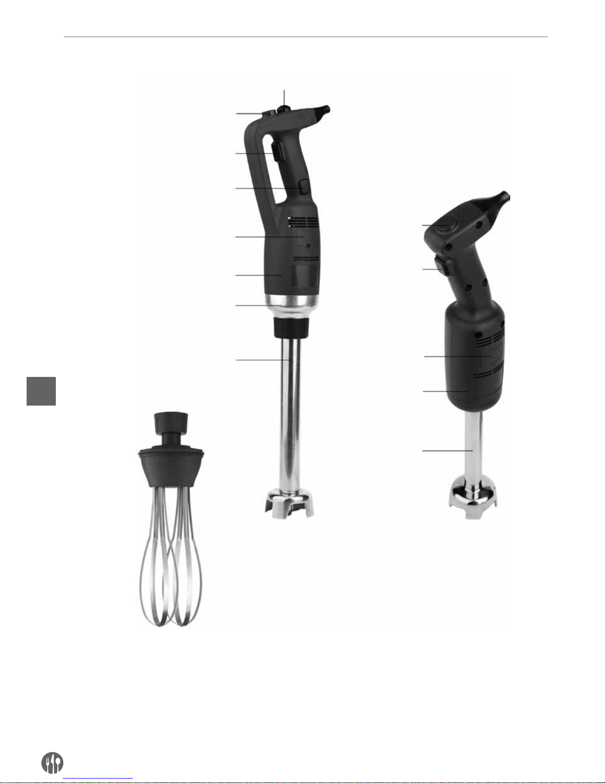
54
PL
Opis produktu
Pokrętło prędkości
zmiennej (opcja)
Przycisk prędkości
zmiennej (opcja)
Przycisk zabezpieczenia
Przycisk wł./wył.
Przycisk wł./wył.
Przycisk blokady
Osłona szczotek
Osłona szczotek
Plastikowa obudowa
Plastikowa obudowa
Złączka
Ramię miksujące
(opcja)
Ramię miksujące
Rózga (dołączona jedynie do
modelu 222133)
222171 z dodatkowym
ramieniem miksującym (opcja)
222188 z dodatkowym
ramieniem miksującym (opcja)
Model 222133 z ramieniem blendera 400 mm
222140
Page 55
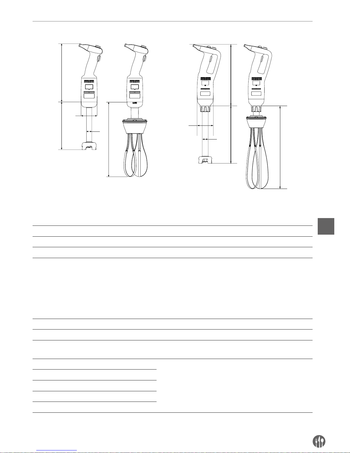
55
PL
Główne parametry techniczne
A
C
B
D
C
D
B
A
C
C
Specyfikacja techniczna
Kod Napięcie
zasilania
Moc Szacunkowa prędkość
obrotów
Szacunkowa waga korpusu
bez ramienia miksującego
lub ubijającego
A
(Długość)B(Średnica)
222140 23 0 V/ 5 0 Hz 220 W 4 000 ~ 20 000 obr./min. 1,15 kg 304 mm Ø 75 mm
222171 23 0 V/ 5 0 Hz 350 W 4 000 ~ 16 000 obr./min. 1,76 kg 359 mm Ø 91 mm
222188 23 0 V/ 5 0 Hz 500 W 4 000 ~ 16 000 obr./min. 1,98 kg 359 mm Ø 91 mm
Uwaga: Specyfikacja techniczna może ulec zmianie bez uprzedzenia.
Tabela kombinacji z podłączeniem ramienia miksującego i ubijającego.
Podane akcesoria nie są dołączone do produktu.
Kod Waga C
(Długość)D(Średnica)
Opis
222164 0,81 kg 185 mm – Ramię ubijające do modelu 222140 (opcjonalne)
– 0,46 kg 160 mm Ø 25 mm Ramię miksujące do modelu 222140 (dołączone do produktu)
222263 0,86 kg 250 mm –
Ramię ubijające do modeli 222171
(opcjonalne)
i 222188
(opcjonalne)
222218 0,69 kg 200 mm Ø 35 mm
Ramię miksujące do modelu 222171 (opcjonalne)
i 222188 (opcjonalne)
222225 0,82 kg 250 mm Ø 35 mm
222232 1,02 kg 300 mm Ø 35 mm
222249 1,28 kg 400 mm Ø 35 mm
222256 1,56 kg 500 mm Ø 35 mm
Uwagi: Model 222133 - zestaw - obejmuje 222171 + 222249 + 222263 + wieszak ścienny + zestawy montażowe
(2 zestawy śrub mocujących, podkładek i kołków rozporowych).
Model: 222140 Modele: 222171/222188
Page 56

56
PL
Wstęp
•
Przed skorzystaniem z urządzenia uważnie zapoznać się z niniejszą instrukcją obsługi. Zawiera
ona ważne informacje dotyczące bezpieczeństwa
użytkownika, jak również wskazówki dotyczące
korzystania i konserwacji urządzenia.
•
Urządzenie przeznaczone jest do profesjonalnego
użytku w lodziarniach, restauracjach, kuchniach
hotelowych w celu przyrządzenia lodów, zup warzywnych, puree, sosów, farszu, majonezu, pasty
pomidorowej, pesto itd.
•
Aby w pełni wykorzystać możliwości miksera
ręcznego, należy dobrze poznać jego funkcje.
•
Konserwacja urządzenia polega na kilku prostych
czynnościach, które może wykonywać operator.
•
Aby zapewnić długi okres eksploatacji urządzenia i obniżenie kosztów użytkowania, postępować
zgodnie z instrukcją.
•
Urządzenie zostało zaprojektowane przez producenta w taki sposób, aby zapewnić bezpieczeństwo użytkowania. Zdjęcie zabezpieczeń zainstalowanych przez producenta w znacznym stopniu
obniży bezpieczeństwo korzystania z urządzenia.
•
Aby zapewnić bezpieczeństwo, postępować zgodnie z instrukcjami podczas instalacji i podłączania
urządzenia do źródła zasilania.
•
Urządzenie instalować w środowisku roboczym
wolnym od czynników korozyjnych.
•
Obszar instalacji nie może być zagrożony wybuchem.
•
Stosować wyłącznie dołączone CZĘŚCI ZAMIENNE.
•
Niniejsza instrukcja stanowi integralną część
urządzenia, dlatego przechowywać ją w bezpiecznym miejscu. Funkcje, dane i rysunki przedstawione w niniejszej instrukcji stanowią wyłączną
własność producenta.
•
Funkcje urządzenia umożliwiają przygotowanie
następujących rodzajów żywności w najkrótszym
możliwym czasie: gęstych przecierów warzywnych, zup, puree ziemniaczanego, kremów, ciast,
majonezu, miazgi migdałowej, serków kremowych itp.
Przygotowania przed zamontowaniem wieszaka do ściany (wyłącznie model 222133)
Przed wykonaniem montażu: Sprawdź wieszak ścienny pod kątem uszkodzeń i kompletności zestawów montażowych (2 zestawów śrub mocujących, podkładek i kołków rozporowych). Jeśli wieszak ścienny jest uszkodzony lub niekompletny, NIE WYKONUJ montażu.
Uwaga:
• Skonsultuj się z wykwalifikowanym wykonawcą lub specjalistą w zakresie montażu, jeśli nie
masz pewności w kwestii konstrukcji ściany. Ma
to na celu zapewnienie prawidłowego i bezpiecznego montażu urządzenia.
• Ze względów bezpieczeństwa montaż powinien
być przeprowadzany przez wykwalifikowanych
techników.
• Rozstaw otworów na śruby montażowe powinien
wynosić ok. 217 mm. Przed rozpoczęciem pracy
uporządkuj miejsce wykonywania montażu.
• Ważne informacje: Przed rozpoczęciem montażu
wieszaka upewnij się, czy dostępne są wszystkie
narzędzia, takie jak śrubokręt, wiertarka elektryczna, miarka, ołówek (brak w zestawie).
• Wieszak musi zostać stabilnie zamocowany do
ściany za pomocą dwóch śrub mocujących z kołkami rozporowymi.
• Pamiętaj, że w obszarze montażu mogą znajdować się elementy takie jak kanały, przewody elektryczne oraz rury. Zachowaj szczególną ostrożność podczas montażu.
Page 57
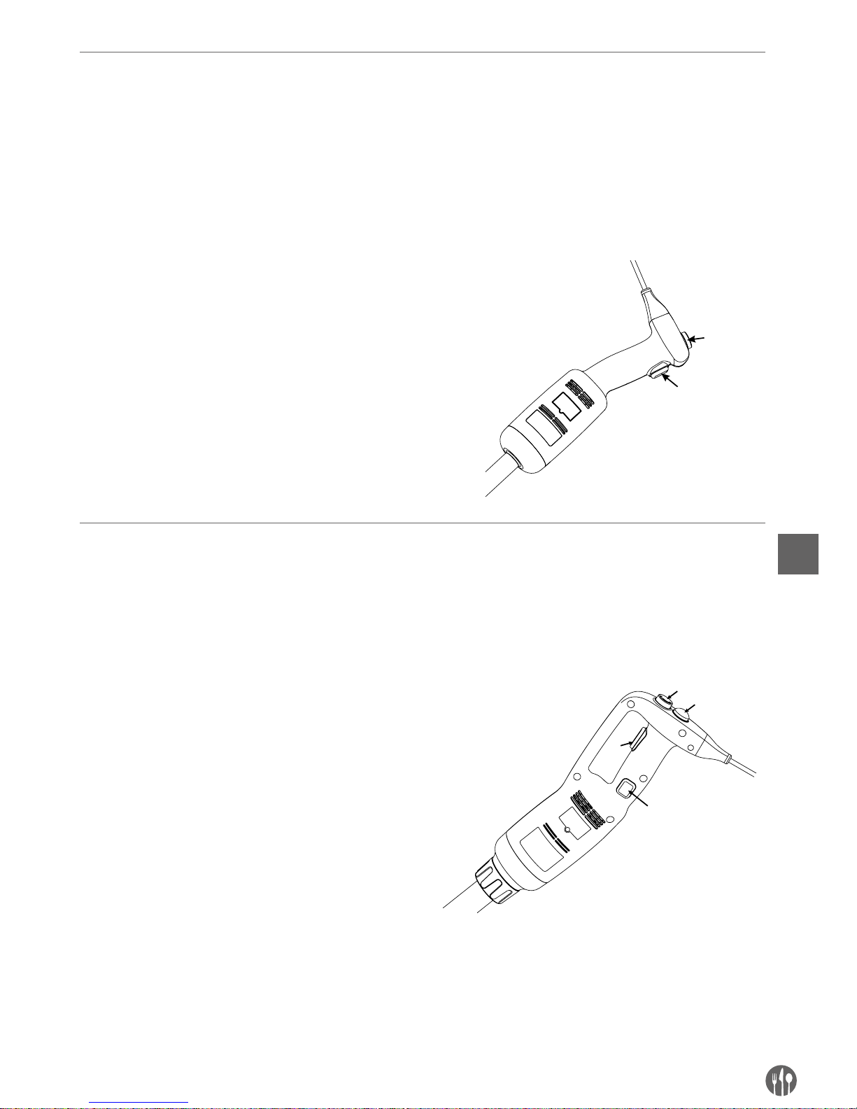
57
PL
INSTRUKCJA OBSŁUGI
INSTRUKCJA OBSŁUGI (MODEL 222140):
UWAGA! Przed podłączeniem urządzenia do źródła zasilania, bezwzględnie sprawdzić, czy specyfikacja urzą-
dzenia na tabliczce znamionowej odpowiada parametrom w gniazdku, do którego ma być podłączone niniejsze
urządzenie.
UWAGA! Model 222140 nie posiada funkcji zablokowania umożliwiającej nieprzerwaną pracę urządzenia.
OBSŁUGA URZĄDZENIA:
1. Upewnić się, czy urządzenie nie jest podłączone
do źródła prądu przed montażem części.
2. Podłączyć ramię miksujące / ubijające do korpusu.
3. Podłączyć urządzenie do źródła zasilania.
4. Sprawdzić, czy przycisk wł./wył. (do uzupełnienia) jest wyłączony (ustawiony płasko).
5. Następnie wcisnąć przycisk wł./wył (do uzupełnienia). Urządzenie uruchomi się. ZACHOWAĆ
OSTROŻNOŚĆ!
6. By wyłączyć urządzenie, zwolnić przycisk wł./wył.
1
2
Instrukcja obsługi (modele: 222171 i 222188):
UWAGA! Przed podłączeniem urządzenia do źródła zasilania, sprawdzić, czy specyfikacja urządzenia na tabliczce znamionowej odpowiada parametrom w gniazdku, do którego ma być podłączone niniejsze urządzenie.
UWAGA: Modele 222171 i 222188 posiadają funkcję zablokowania umożliwiającą nieprzerwaną pracę urządzenia.
URUCHAMIANIE I ZATRZYMYWANIE URZĄDZENIA
1. Upewnić się, czy urządzenie nie jest podłączone
do źródła prądu przed montażem.
2. Podłączyć ramię miksujące / ubijające do korpusu.
3. Podłączyć urządzenie do źródła zasilania.
4. Sprawdzić, czy przycisk wł./wył. (3) jest wyłączony (ustawiony płasko).
5. Najpierw należy wcisnąć i przytrzymać przycisk
zabezpieczenia (1).
6. Następnie należy wcisnąć przycisk wł./wył. (3)
i przytrzymać jednocześnie z przyciskiem zabezpieczenia. Urządzenie uruchomi się. ZACHOWAĆ
OSTROŻNOŚĆ!
7. By zatrzymać pracę urządzenia, należy zwolnić
przycisk wł./wył. (3) oraz przycisk zabezpieczenia
(1).
1
2
3
4
Page 58

58
PL
PRACA CIĄGŁA:
Postępować zgodnie z punktami 1-6 powyżej, a następnie:
• Nadal wciskając przycisk wł./wył. (3), przesunąć
palec z przycisku zabezpieczenia (1) na przycisk
blokady (4).
•
Zwolnić przycisk wł./wył. (3) oraz przycisk zabezpieczenia (4) - urządzenie uruchomi się w trybie
pracy ciągłej.
•
By wyłączyć urządzenie, nacisnąć i zwolnić przycisk wł./wył. (3).
ZMIANA PRĘDKOŚCI (Modele: 222140, 222171 i 222188 )
Postępować zgodnie z punktami 1-6 powyżej, a następnie:
• Zmienić prędkość pracy silnika obracając pokrętło zmiany prędkości (2) na wartość niższą
lub wyższą (według uznania). Jeśli używane jest
ramię ubijające, zaleca się uruchomienie urzą-
dzenie z niską prędkością. Dzięki systemowi au-
tomatycznej regulacji prędkości, wybrana prędkość pozostaje stała nawet w przypadku zmiany
konsystencji mieszanych składników.
UWAGA:
Funkcja miksera: Aby zapewnić lepszą kontrolę,
zalecamy przytrzymywanie uchwytu miksera i dolnej części korpusu silnika. Zalecamy także lekko
przechylić mikser, tak aby końcówka ramienia nie
dotykała dna naczynia. Zawsze sprawdzać, czy
końcówka jest zanurzona odpowiednio głęboko,
aby uniknąć rozprysków i przedostania się cieczy
przez otwory wentylacyjne jednostki silnika. Aby
zapewnić optymalną wydajność, dwie trzecie ramienia należy zanurzyć w przygotowywanej mieszaninie.
Funkcja ubijania: Można także trzymać urządzenie
jedną ręką, a drugą w razie potrzeby przytrzymywać miskę. Podczas ubijania zalecamy przesuwanie ramienia ubijającego wokół misy, aby zapewnić
jednolite ubicie masy. Uważać, aby nie dotykać
ścianek misy ramieniem ubijającym. Aby zapewnić
maksymalną wydajność, należy zanurzyć przynajmniej jedną piątą długości ramienia. Nigdy nie zanurzać uchwytu.
Page 59
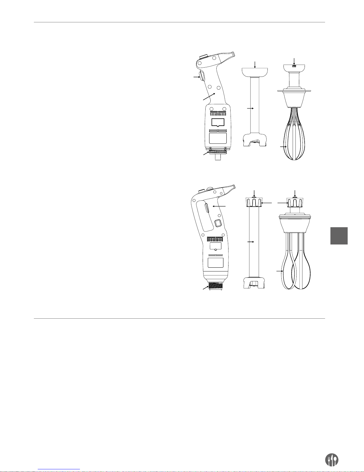
59
PL
Montaż / demontaż części urządzenia
Montaż / demontaż części urządzenia należy przeprowadzać przy urządzeniu wyłączonym i odłączonym od zasilania.
Montaż: Model 222140:
1. Dopasować i włożyć złączkę (5) ramienia miksującego (3) albo ubijającego (6) w złączkę (2) korpusu urządzenia (1).
2. Dokręcić dokładnie ramię miksujące (3) albo ubijające (6) do korpusu (1).
Montaż: Modele 222171 i 222188:
1. Dopasować i włożyć złączkę (5) ramienia miksującego (3) albo ubijającego (4) w złączkę (2)
korpusu urządzenia (1). Upewnić się, czy węższa
strona złączki urządzenia jest dopasowana do
wklęsłej strony złączki ramienia miksującego (3)
lub ubijającego (4).
2. Dokręcić dokładnie nakrętkę (6) do korpusu (1).
4
3
5
2
6
5
4
2
3
1
6
5 5
1
Aby zdemontować akcesoria, należy przeprowadzić powyższe czynności w odwrotnej kolejności.
Instrukcja mycia
Przed przystąpieniem do mycia, zawsze odłączać
urządzenie od zasilania.
• Po użyciu miksera ręcznego w gorącej miesza-
ninie, należy schłodzić ramię miksujące w zimnej wodzie przed zdjęciem końcówki z ramienia
miksującego. Po zakończeniu pracy niezwłocznie
umyć ramię, aby uniknąć przywierania resztek
mieszaniny.
• Nigdy nie zanurzać silnika ani uchwytu w wodzie,
czyścić wilgotną ściereczką albo gąbką.
• Czyszczenie ramienia miksującego i końców-
ki: Umieścić ramię i końcówkę w odpowiednim
naczyniu napełnionym czystą wodą i włączyć
urządzenie na kilka sekund.
• OSTRZEŻENIE: Po umyciu zawsze dokładnie
osuszać ostrza, aby uniknąć powstawania plamek rdzy.
• Nigdy nie zanurzać uchwytu ramienia ubijającego
w wodzie, czyścić wilgotną ściereczką albo gąbką.
• Po każdym użyciu urządzenie należy czyścić za
pomocą detergentu albo środka dezynfekującego, nie używać jednak nigdy czystego wybielacza.
Do czyszczenia części plastikowych nie używać
detergentów alkalicznych.
Page 60
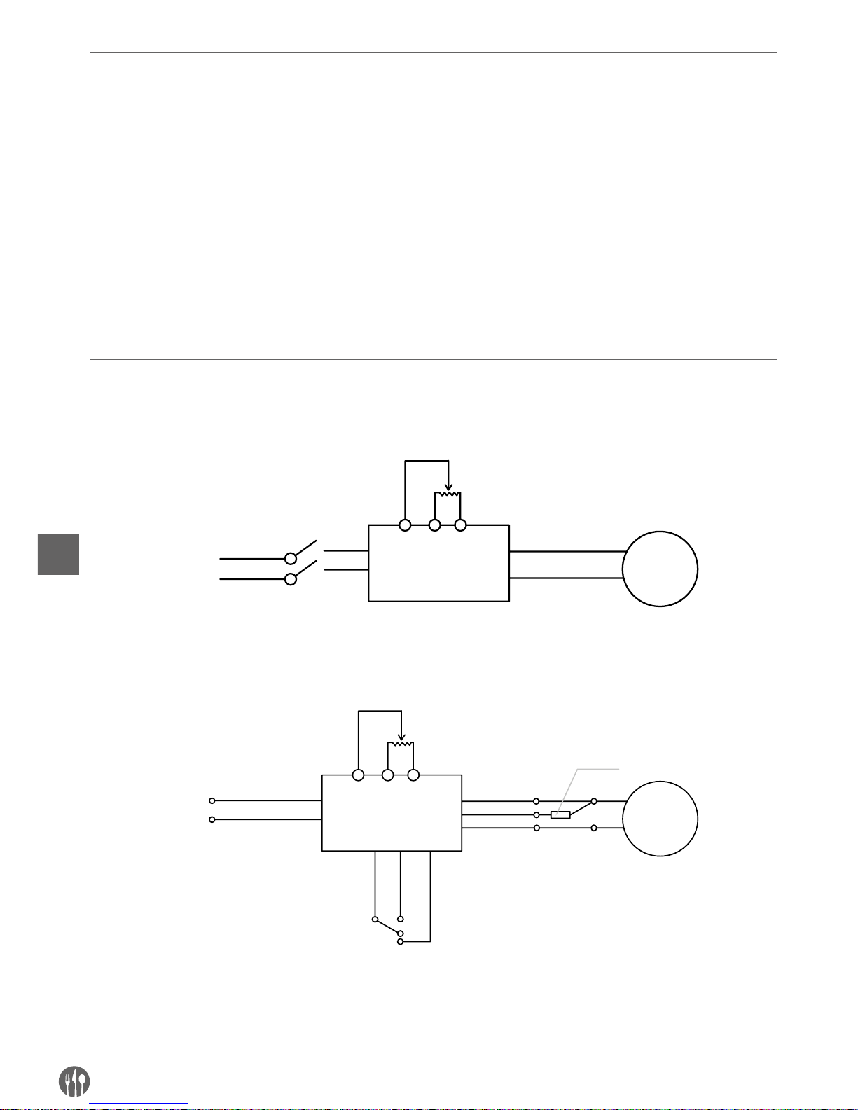
60
PL
Rozwiązywanie problemów
W przypadku przerwy w zasilaniu albo odłączenia
urządzenia, zwolnić przycisk wł./wył. (3), sprawdzić
zasilanie i uruchomić ponownie urządzenie.
Jeśli urządzenie zostanie wyłączone w wyniku
przegrzania, zwolnić przycisk wł/.wył. (3), odłączyć
urządzenie od zasilania, odczekać kilka minut, aż
silnik ostygnie, a zabezpieczenie przed przegrzaniem zresetuje się; następnie ponownie uruchomić
urządzenie.
Jeśli nie można ustalić przyczyny problemu: zwolnić przycisk wł./wył. (CB), odłączyć urządzenie od
zasilania i sprawdzić:
1. wtyczkę,
2. czy ostrza w końcówce obracają się swobodnie,
3. stan kabla zasilającego,
4. czy wał napędowy swobodnie się obraca. W tym
celu zdjąć końcówkę i ręcznie sprawdzić, czy
końcówka wału obraca się.
W przypadku wystąpienia awarii, która nie jest opisana w instrukcji, skontaktować się ze sprzedawcą
urządzenia albo przekazać urządzenie do autoryzowanego serwisu.
Schemat elektryczny
Model 222140
AC230V
PC
BM
NO
NO
Potencjometr
Silnik
Wyłącznik
Model 222171 i 222188
AC230V
PCB
M
NOCom
Nc
Potencjometr
Silnik
Wyłącznik
Wyłącznik termiczny
Page 61
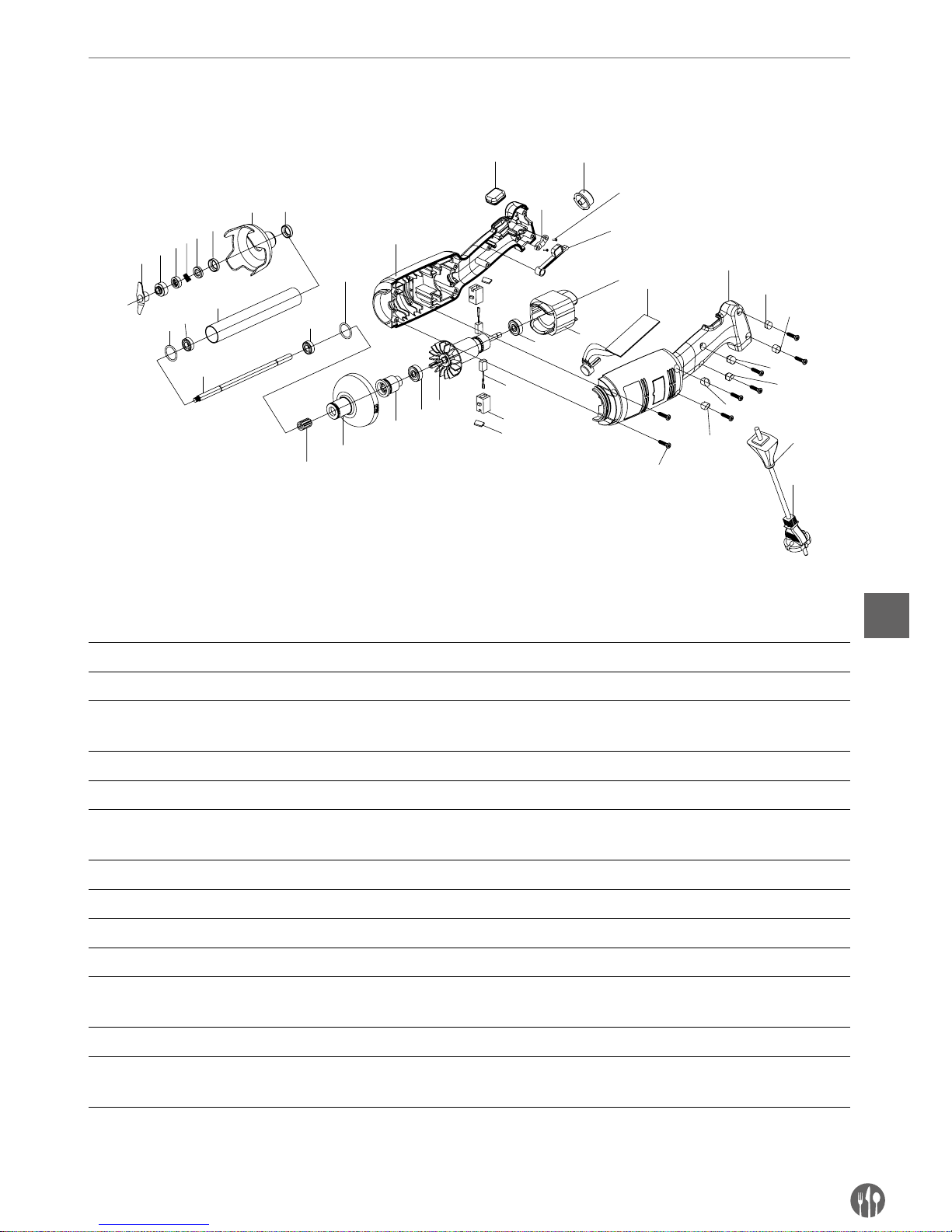
61
PL
Rysunek eksplozyjny i wykaz części modelu 222140
Model 222140
1
2
4
5
6
7
9
10
11
12
10
9
13
14
15
16
17
19
18
16
20
22
23
25
29-1
31
21
27
24
22
29-2
29-3
29-4
29-5
29-6
30
28
3
26
8
18-1
WYKAZ CZĘŚCI - MODEL 222140 KORPUS I RAMIĘ MIKSUJĄCE
Nr Nazwa części Nr Nazwa części Nr Nazwa części
1 Nóż 14 Plastikowa obudowa głowicy 26 Śruba listwy dociskowej
2 Pierścień wklęsły 15 Tuleja wielowpustowa 27 Styczny trzon przełącznika
3 Grafitowa sprężyna
pierścieniowa
16 Łożysko 28 Śruba obudowy
4 Grafitowy pierścień 17 Wirnik 29-1 Trzpień gwintowany 28-1
5 Ceramiczny pierścień 18 Uchwyt na szczotkę 29-2 Trzpień gwintowany 28-2
6 Ceramiczna tuleja
pierścieniowa
18-1 Osłonka szczotki 29-3 Trzpień gwintowany 28-3
7 Osłona noża 19 Szczotka 29-4 Trzpień gwintowany 28-4
8 Tuleja łożyskowa 20 Stojan 29-5 Trzpień gwintowany 28-5
9 Pierścień uszczelniający 21 Płyta sterująca prędkością 29-6 Trzpień gwintowany 28-6
10 Łożysko W688Z 22 Obudowa lewa i prawa 30 Osłona kabla
11 Tuleja ze stali nierdzewnej 23
Gumowe zabezpieczenie
przed zablokowaniem
31 Przewód zasilania
12 Tuleja wydająca 24 Listwa dociskowa
13 Wypust 25 Przycisk sterowania
prędkością
Page 62
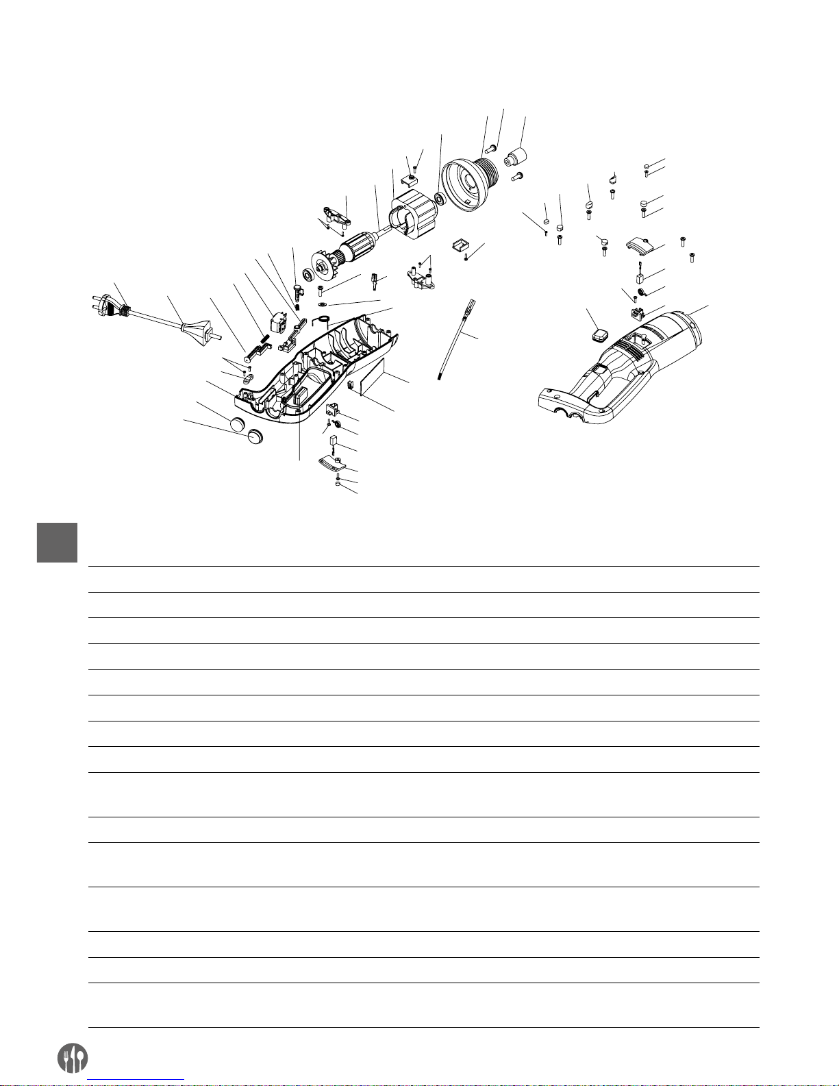
62
PL
RYSUNEK EKSPLOZYJNY I WYKAZ CZĘŚCI MODELI 222171 I 222188 (WYŁĄCZNIE KORPUS)
12
13
14
17
18
20
21
23
24
25
26
29
30
31
32
37
5
6
7
8
22
27
33
28
9
4
9
9
2
1-1
28
35
36
34
38
16
15
2
39
1-1
2
4
5
6
7
8
1-3
1-4
1-7
1-5
1-6
3
10
11
19
1-2
9
WYKAZ CZĘŚCI MODELI 222171 I 222188 (WYŁĄCZNIE KORPUS)
Nr Nazwa części Nr Nazwa części Nr Nazwa części
1-1 Trzpień gwintowany 1 11 Obudowa lewa 26 Osłona kabla
1-2 Trzpień gwintowany 2 12 Tuleja wielowpustowa 27 Przewód zasilania
1-3 Trzpień gwintowany 3 13 Głowica aluminiowa 28 Śruba listwy dociskowej
1-4 Trzpień gwintowany 4 14 608 Łożysko 29 Listwa dociskowa
1-5 Trzpień gwintowany 5 15
Śruba mocowanej płytki silnika
30 Obudowa prawa
1-6 Trzpień gwintowany 6 16 Mocowana płytka silnika 31 Gumowy przycisk
2 Śruba 3*12 CB 17
Stojan
(w zależności od modelu)
32
Przycisk sterowania prędkością
3 Śruba 3*15 CB 18
Wirnik
(w zależności od modelu)
33 Gniazdo przełącznika
4 Śruba M4*1 19 Zamocowany uchwyt na
szczotkę
34 Wtyczka męska
5 Osłonka szczotki 20 (W zależności od modelu) 35 Płyta sterująca prędkością
6 Szczotka 21 Sworzeń blokady 36
Sprężyna stycznego trzonu
przełącznika
7 3246 Sprężyna cylindra
szczotki
22 Styczny trzon przełącznika 37 Płyta sterująca prędkością
8 Uchwyt na szczotkę 23 Przełącznik 38 Wtyczka żeńska
9 Śruba 3*12 CB 24 Sprężyna sworznia 39 Przewód do wtyczki żeńskiej
10
Gumowe zabezpieczenie
przed zablokowaniem
25 Sworzeń
Page 63
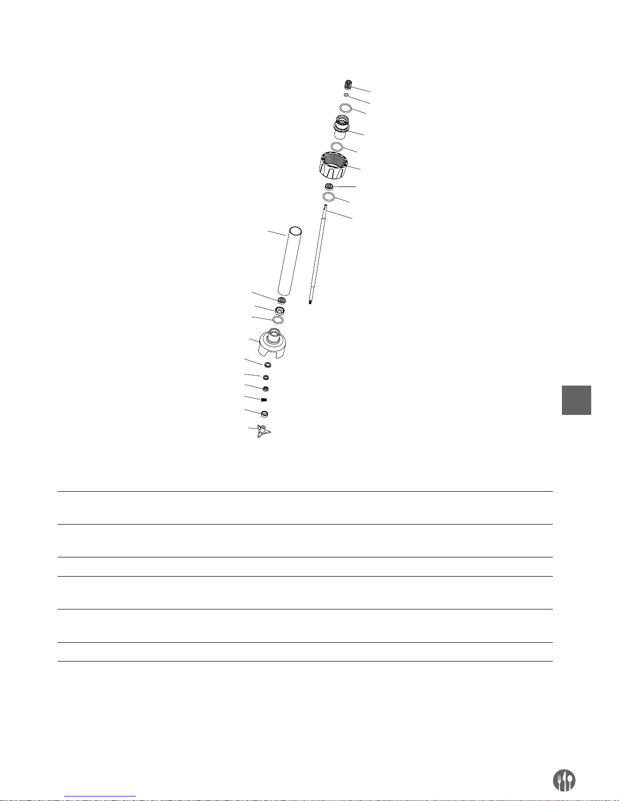
63
PL
RAMIONA MIKSUJĄCE (OPCJONALNE) DO MODELI 222171, 222188
1
3
6
7
8
6
9
4
10
11
13
15
16
2
5
12
14
4
4
4
WYKAZ CZĘŚCI - RAMIONA MIKSUJĄCE (OPCJONALNE): 222218, 222225, 222232, 222249, 222256
Nr Nazwa części Nr Nazwa części Nr Nazwa części
1 Tuleja wielowpustowa 7 Tuleja wydająca
(w zależności od modelu)
13 Grafitowy pierścień
2 Pierścień uszczelniający
tulei wielowpustowej
8
Tuleja ze stali nierdzewnej
304 (w zależności od modelu)
14 Grafitowa sprężyna
pierścieniowa
3 Tuleja łącząca 9 Tuleja łożyskowa 15 Pierścień wklęsły
4 Pierścień uszczelniający
tulei łączącej
10 Osłona noża 16 Nóż
5 Tuleja mocująca 11 Ceramiczna tuleja
pierścieniowa
6 Łożysko 608 12 Pierścień ceramiczny
Page 64
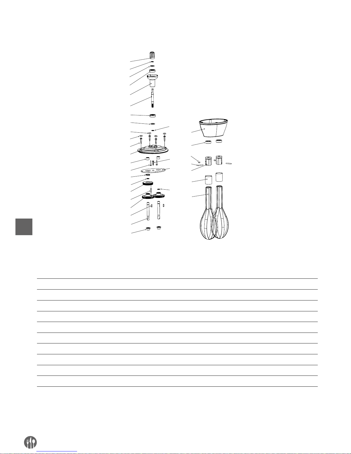
64
PL
RAMIĘ UBIJAJĄCE (OPCJONALNE) DLA MODELU 222140
1
2
3
4
5
6
3
4
8
9
11
12
13
2
14
15
16
17
18
19
20
21
22
23
24
25
26
10
7
27
2
28
2
WYKAZ CZĘŚCI - RAMIĘ MIKSUJĄCE (OPCJONALNE): MODEL 222164
Nr Nazwa części Nr Nazwa części Nr Nazwa części
1 Tuleja wielowpustowa 11 Łożysko igiełkowe 21 Uszczelniacz olejowy
2 Pierścień sprężynujący Ø8 12 Śruba 22 Śruba M4x5
3 Uszczelka łożyska 13 Pierścień sprężynujący Ø16 23 Bolczyk cylindryczny
4 Łożysko 14 Łożysko przekładni spiralnej 24 Mocowana listwa
5 Tuleja łącząca 15 Bolczyk cylindryczny 25 Stalowy pierścień
6 Łożysko przekładni spiralnej 16 Przekładnia prosta 26 Stalowy słupek
7 Trzpień gwintowany 2 17 Przycisk 27 Sitko
8 Trzpień gwintowany 1 18 Tuleja wydająca 28 Śruba
9 Śruba obudowy 19 Tuleja ramienia
10 Pokrywa górna 20 Pokrywa dolna
Page 65
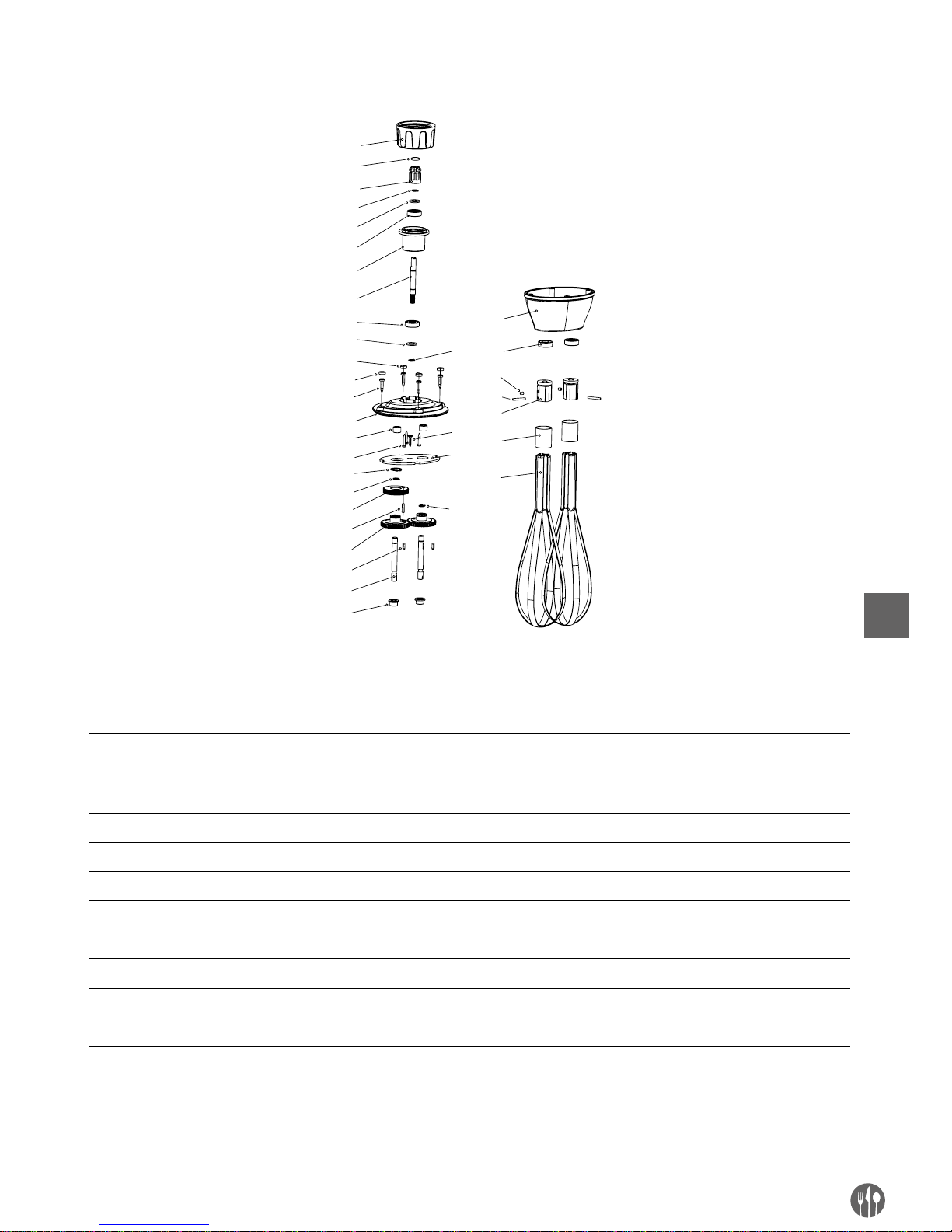
65
PL
RAMIONA UBIJAJĄCE (OPCJONALNE) DLA MODELI 222171 I 222188
3
4
5
6
7
8
5
6
10
11
13
14
15
4
1
6
17
18
19
20
21
22
23
24
25
26
27
28
12
9
29
4
4
30
1
2
WYKAZ CZĘŚCI - RAMIĘ MIKSUJĄCE (OPCJONALNE): MODEL 222263
Nr Nazwa części Nr Nazwa części Nr Nazwa części
1 Tuleja mocująca 11 Śruba obudowy 21 Tuleja ramienia
2 Pierścień uszczelniający tulei
wielowpustowej
12 Pokrywa górna 22 Pokrywa dolna
3 Tuleja wielowpustowa 13 Łożysko igiełkowe 23 Uszczelniacz olejowy
4 Pierścień sprężynujący Ø8 14 Śruba 24 Śruba M4x5
5 Uszczelniacz olejowy 15 Pierścień sprężynujący Ø16 25 Bolczyk cylindryczny
6 Łożysko 16 Łożysko przekładni spiralnej 26 Mocowana listwa
7 Tuleja łącząca 17 Bolczyk cylindryczny 27 Stalowy pierścień
8 Łożysko przekładni spiralnej 18 Przekładnia prosta 28 Stalowy słupek
9 Trzpień gwintowany 2 19 Przycisk 29 Sitko
10 Trzpień gwintowany 1 20 Tuleja wydająca 30 Śruba
Page 66

66
PL
Gwarancja
Każda wada bądź usterka powodująca niewłaściwe
funkcjonowanie urządzenia, która ujawni się w ciągu jednego roku od daty zakupu, zostanie bezpłatnie usunięta lub urządzenie zostanie wymienione
na nowe, o ile było użytkowane i konserwowane
zgodnie z instrukcją obsługi i nie było wykorzystywane w niewłaściwy sposób lub niezgodnie z przeznaczeniem. Postanowienie to w żadnej mierze nie
narusza innych praw użytkownika wynikających z
przepisów prawa. W przypadku zgłoszenia urzą-
dzenia do naprawy lub wymiany w ramach gwarancji należy podać miejsce i datę zakupu urządzenia i
dołączyć dowód zakupu (np. paragon).
Zgodnie z naszą polityką ciągłego doskonalenia
wyrobów zastrzegamy sobie prawo do wprowadzania bez uprzedzenia zmian w wyrobie, opakowaniu
oraz danych technicznych podawanych w dokumentacji.
Wycofanie z użytkowania i ochrona środowiska
Urządzenie zużyte i wycofane z użytkowania należy zutylizować zgodnie z przepisami i wytycznymi
obwiązującymi w momencie wycofania urządzenia.
Materiały opakowaniowe, jak tworzywa sztuczne i
pudła, należy umieszczać w pojemnikach na odpady właściwych dla rodzaju materiału.
Page 67

67
FR
Cher client,
Merci d’avoir acheté cet appareil de Hendi. Veuillez lire attentivement ce mode d’emploi avant de brancher l’appareil afin d’éviter tout endommagement pour cause d’usage abusif. Veuillez notamment lire les
consignes de sécurité avec la plus grande attention.
Règles de sécurité
• L’utilisation abusive et le maniement incorrect de l’appareil peuvent entraîner une grave
détérioration de l’appareil ou provoquer des blessures.
• Cet appareil est conçu exclusivement à des fins commerciales et non pour un usage
domestique.
• L’appareil doit être utilisé uniquement pour le but il a été conçu. Le fabricant décline
toute responsabilité en cas de dommage consécutif à un usage abusif ou un maniement
incorrect.
• Veillez à tenir l’appareil et la prise électrique hors de portée de l’eau ou de tout autre li
quide. Si malencontreusement l’appareil tombe dans l’eau, débranchez immédiatement
la prise électrique et faites contrôler l’appareil par un réparateur agréé. La non-observa
tion de cette consigne entraîne un risque d’accident mortel.
• Ne tentez jamais de démonter vous-même le bâti de l’appareil.
• N’enfoncez aucun objet dans la carcasse de l’appareil.
• Ne touchez pas la prise avec les mains mouillées ou humides.
• Risque d’électrocution! Ne tentez jamais de réparer l’appareil. Tous défauts et dysfonc
tionnement doivent être supprimés par le personnel qualifié.
• N’utilisez jamais l’appareil endommagé! Débranchez l’appareil endommagé de l’ali
mentation électrique et contactez votre revendeur.
• Avertissement: N’immergez pas les pièces électriques de l’appareil dans l’eau ou dans
d’autres liquides. Ne mettez pas l’appareil sous l’eau courante.
• Vérifiez régulièrement la fiche et le câble d’alimentation pour les dommages. La fiche
ou le câble d’alimentation endommagé(e) transmettre pour la réparation au service ou
à une personne qualifiée, pour prévenir tous les menaces ou les blessures possibles.
• Assurez-vous que le câble d’alimentation n’est pas en contact avec les objets pointus ou
chauds ; gardez le câble loin des flammes nues. Pour retirer la fiche de la prise murale,
tirez toujours en tenant la fiche et non le câble d’alimentation.
• Protégez le câble d’alimentation (ou la rallonge) contre le débranchement accidentel de
la prise murale. Le câble doit être posé de manière ne provocant pas les chutes acciden
-
telles.
• Surveillez en permanence l’appareil pendant l’utilisation.
• Avertissement ! Si la fiche est insérée dans la prise murale, l’appareil doit être considéré
comme branché à l’alimentation.
• Avant de retirer la fiche de la prise, éteignez l’appareil !
• Ne transportez jamais l’appareil en tenant le câble.
• N’utilisez aucuns accessoires qui n’ont pas été fournis avec l’appareil.
Page 68

68
FR
• L’appareil doit être branché à la prise murale avec une tension et la fréquence indiquées
sur la plaque signalétique.
• Insérez la fiche à la prise murale située dans un endroit facilement accessible de sorte
qu’en cas de panne l’appareil puisse être immédiatement déconnecté. Pour éteindre
complètement l’appareil, débranchez-le de la source d’alimentation. Pour cela, retirez la
fiche à l’extrémité du câble d’alimentation de la prise murale.
• Eteignez l’appareil avant de débrancher l’appareil de la prise!
• N’utilisez jamais les accessoires non recommandés par le fabricant. L’utilisation des ac
cessoires non recommandés peut présenter des risques pour l’utilisateur et provoquer
les dommages à l’appareil. Utilisez uniquement des pièces et accessoires originaux.
• Cet appareil n´est pas apte à être utilisé par des personnes (enfants compris) avec capa
cités physiques, sensorielles ou intellectuelles diminuées ou ne possédant pas l´expérience et les connaissances suffisantes.
• Ne laissez jamais les enfants utiliser l’appareil.
• L’appareil et le câble d’alimentation doivent être stockés hors de la portée des enfants.
• Ne permettez pas aux enfants d’utiliser l’appareil pour jouer
• Débranchez toujours l’appareil de l’alimentation s’il doit être laissé sans surveillance et
également avant le montage, le démontage et le nettoyage.
• Ne laissez jamais l’appareil sans surveillance lorsqu’il est utilisé.
Regles de securite speciales
• L’appareil est exclusivement destiné à mixer, émulsionner et mélanger des produits alimentaires chauds et froids pour des fins commerciales. L’appareil sert à préparer des
soupes, des purées, des crèmes, de la masse de massepain, du fromage à la crème,
etc. directement dans le plat. L’utilisation de l’appareil à d’autres fins peut entraîner des
dommages ou des blessures.
• N’utilisez l’appareil que conformément aux instructions.
• L’appareil ne doit être utilisé que par du personnel de cuisine qualifié, des cantines ou
un service de bar, etc.
• Lorsque l’appareil est laissé sans surveillance et avant le montage, le démontage et
le nettoyage, déconnectez-le obligatoirement de la source d’alimentation en retirant la
fiche de la prise murale.
• Pendant le fonctionnement de l’appareil ne dirigez la lame vers quelqu’un d’autre qui se
trouve à proximité.
• Pendant le fonctionnement de l’appareil ne touchez pas la lame ou d’autres pièces mo
biles. Pendant le fonctionnement de l’appareil ne touchez pas les éléments mobiles avec
vos mais ou d’autres ustensiles de cuisine ; attachez vos cheveux.
• Séchez complètement l’appareil et ses accessoires avant de brancher l’appareil à l’ali
mentation électrique.
• Risque de lésions et de blessures aux mains! Manipulez attentivement la lame de l’ap
pareil – elle est tranchante.
• N’ajoutez pas des ingrédients dans un récipient pendant le fonctionnement de l’appareil.
Page 69

69
FR
Attention: Débranchez l’appareil de l’alimentation électrique immédiatement après l’utilisation ou avant d’enlever ou de changer d’accessoires.
Pour installer sur le mur le support fourni avec le modèle 222133 lisez attentivement les
instructions de sécurité suivantes :
• Pour des raisons de sécurité, le montage doit être effectué par un technicien qualifié.
• Avant l’installation, vérifiez que le mur peut supporter la charge totale de l’appareil et de
ses accessoires.
• Assurez-vous qu’il n’y a pas de câbles électriques, installations d’eau, de gaz ou d’autres
composants à proximité du lieu de l’installation.
• Consultez un entrepreneur qualifié ou un spécialiste de montage si vous n’êtes pas sûr
de la structure du mur.
• Serrez les vis. Ne serrez pas trop fort. Un serrage excessif peut endommager les vis et
réduire considérablement la stabilité du montage.
• Ne laissez pas les enfants ou les animaux s’approcher au lieu de l’installation.
• Attention ! Ne placez pas d’autres éléments que l’appareil sur le support pour éviter de
surcharger le support.
Page 70
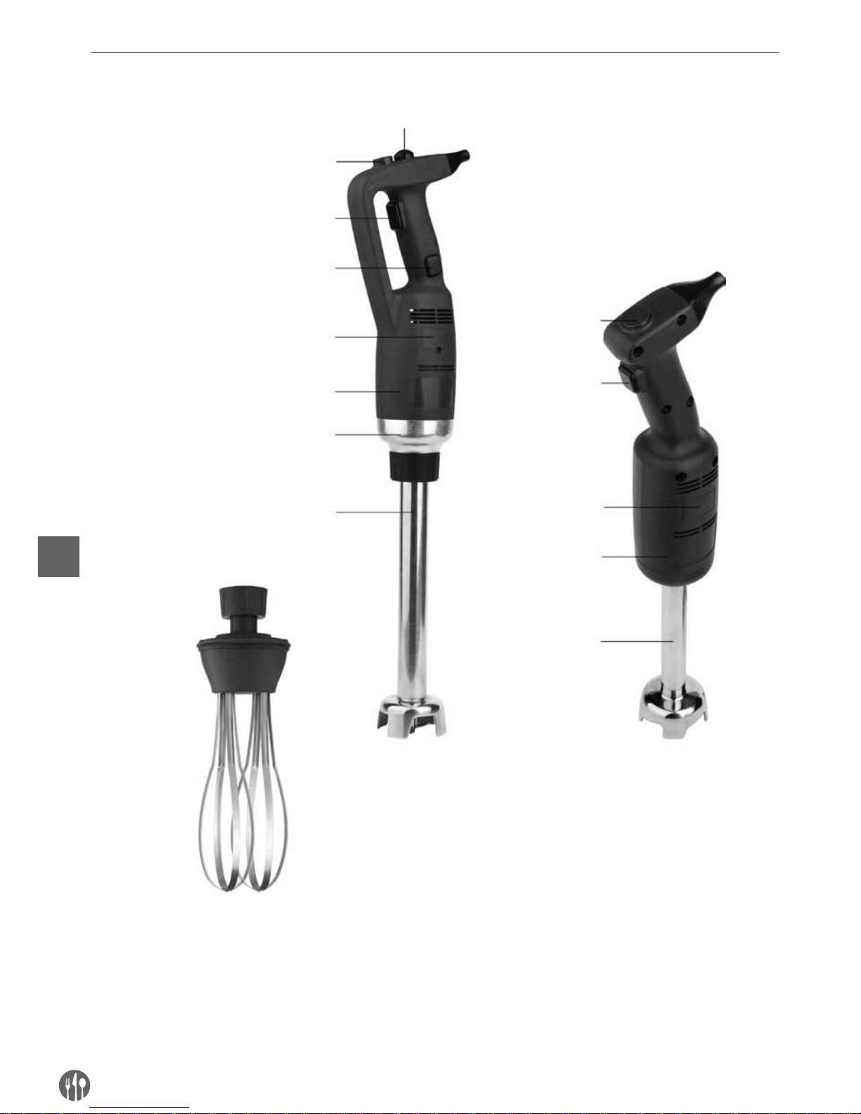
70
FR
Description du produit
Bouton de réglage
de vitesse variable
(option)
Bouton de réglage
de vitesse variable
(option)
Bouton de protection
Bouton de marche /
d’arrêt
Bouton de marche /
d’arrêt
Bouton de verrouillage
Protection
des brosses
Protection
des brosses
Boîtier en plastique
Boîtier en plastique
Connecteur
Fouet mixeur
(option)
Fouet mixeur
Fouet (fourni uniquement avec
le modèle 222133)
222171 avec un fouet
mixeur supplémentaire (option)
222188 avec un fouet
mixeur supplémentaire (option)
Modèle 222133 avec le bras du mixeur
plongeur 400 mm
222140
Page 71
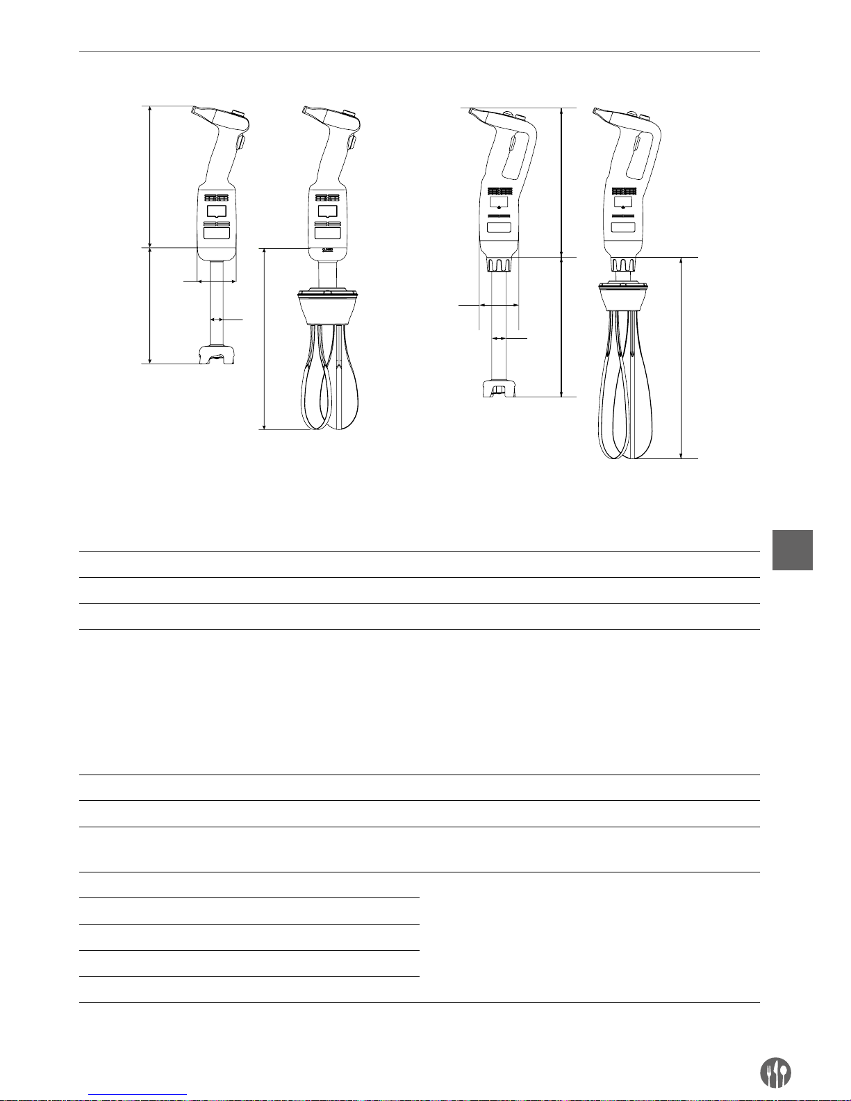
71
FR
Caracteristiques techniques
A
C
B
D
C
D
B
A
C
C
Spécification technique
Code Tension Puissance Vitesse Poids du corps sans
fouet mixeur ou battantA(Longueur)B(Diamètre)
222140 23 0 V/ 5 0 Hz 220 W 4,000 ~ 20,000 tr./min. 1,15 kg 304 mm Ø 75 mm
222171 23 0 V/ 5 0 Hz 350 W 4,000 ~ 16,000 tr./min. 1,76 kg 359 mm Ø 91 mm
222188 23 0 V/ 5 0 Hz 500 W 4,000 ~ 16,000 tr./min. 1,98 kg 359 mm Ø 91 mm
Note : La spécification technique peut être modifiée sans préavis.
Tableau de combinaison avec le fouet mixeur et le fouet battant.
Les accessoires présentés ne sont pas fournis avec le produit.
Code Poids C
(Longueur)
D
(Diamètre)
Description
222164 0,81 kg 185 mm – Fouet battant pour le modèle 222140 (option)
– 0,46 kg 160 mm Ø 25 mm Fouet mixeur pour le modèle 222140 (inclus)
222263 0,86 kg 250 mm –
Fouet battant pour les modèles 222171 (option)
et 222188 (option)
222218 0,69 kg 200 mm Ø 35 mm
Fouet mixeur pour les modèles 222171 (option)
et 222188 (option)
222225 0,82 kg 250 mm Ø 35 mm
222232 1,02 kg 300 mm Ø 35 mm
222249 1,28 kg 400 mm Ø 35 mm
222256 1,56 kg 500 mm Ø 35 mm
Remarques : Modèle 222133 – l’ensemble comprend 222171 + 222249 + 222263 + support mural + kit de montage (2 kits de vis de fixation, rondelles, boulons expansifs).
Modele: 222140 Modeles: 222171/222188
Page 72

72
FR
Introduction
•
Avant d’utiliser l’appareil, lisez attentivement les
informations sur le fonctionnement. Il comprend
des informations importantes concernant la sécurité de l’utilisateur ainsi que des conseils sur la
façon d’utiliser et l’entretien.
•
L’appareil est destiné pour un usage professionnel dans des crémeries, des restaurants, des
cuisines d’hôtel, pour préparer les glaces, les
soupes aux légumes, les purées, les sauces, la
farce, la mayonnaise, la pâte aux tomates ou le
pesto etc.
•
Pour profiter pleinement de l’appareil, lisez attentivement les informations sur ses fonctions.
•
L’entretien de l’appareil consiste à réaliser
quelques activités simples qui peuvent être effectuées par l’opérateur.
•
Pour assurer une longue durée de vie de l’appareil, réduire les coûts de l’utilisation, veuillez respecter les instructions.
•
L’appareil a été conçu pour assurer la sécurité de
l’utilisation.
•
L’élimination des éléments de protection de l’appareil réduira sérieusement la sécurité de l’utilisation de l’appareil.
•
Pour assurer la sécurité, veuillez suivre les instructions lors de l’installation et de la connexion
de l’appareil au réseau.
•
L’appareil doit être installé dans un environnement de travail exempt de toutes matières corrosives.
•
La zone de l’installation peut être potentiellement
explosive.
•
Utilisez uniquement les PIECES DE RECHANGE
ORIGINALES.
•
Le présent mode d’emploi constitue une partie
intégrale de l’appareil et il doit être conservé dans
un endroit sûr. Les fonctions, les données et les
figures du présent mode d’emploi constituent la
propriété exclusive du fabricant.
•
Les fonctions de l’appareil permettent la préparation de plusieurs types d’aliments dans les
plus brefs délais : purées épaisses de légumes,
soupes, purée aux pommes de terre, crèmes,
gâteaux, mayonnaise, pâte d’amande, fromages
crémeux etc.
Préparation au montage mural du support (uniquement le modèle 222133)
Avant le montage: Vérifiez que le support mural n’est pas endommagé et contrôlez l’intégralité des kits de
montage (2 kits de vis de fixation, rondelles, boulons expansifs). Si le support est endommagé ou incomplet
N’EFFECTUEZ PAS le montage.
Remarque:
•
Consultez un entrepreneur qualifié ou un spécialiste si vous n’êtes pas sûr de la structure du mur.
Ceci afin d’assurer l’assemblage correct et sûr de
l’appareil.
•
Pour des raisons de sécurité, le montage doit être
effectué par un technicien qualifié.
•
La distance entre les vis de fixation doit être d’env.
217 mm. Avant de commencer votre travail, rangez le site d’installation.
• Informations importantes: vant le montage, as-
surez-vous que tous les outils sont disponibles,
c’est à dire un tournevis, une perceuse électrique, un mètre pliant, un crayon (non fournis
avec l’appareil).
•
Le support doit être fixé de manière stabile au
mur à l’aide de deux vis de fixation et des boulons
expansifs.
•
N’oubliez pas que dans le lieu de l’installation
peuvent se trouver les éléments tels que des
conduits, des fils électriques et des tuyaux. Soyez
particulièrement prudent pendant l’installation.
Page 73
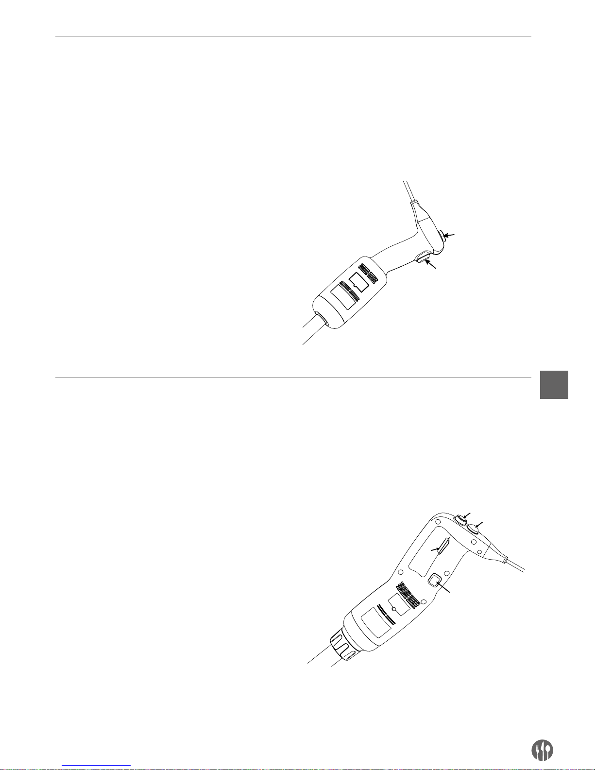
73
FR
Mode d’emploi
MODE D’EMPLOI (MODELE 222140):
NOTE! Avant de brancher l’appareil à une source d’alimentation, assurez-vous que les spécifications de l’ap-
pareil sur la plaque signalétique correspondent aux paramètres locaux.
NOTE! Le modèle 222140 ne possède pas la fonction de verrouillage permettant le fonctionnement continu
e l’appareil.
FONCTIONNEMENT DE L’APPAREIL:
1. Avant de monter les pièces, assurez-vous que
l’appareil n’est pas branché à la source d’alimentation.
2. Installez le fouet mixeur / battant au corps.
3. Branchez l’appareil à une source d’alimentation.
4. Vérifiez si le bouton de marche / d’arrêt est désactivé (en position plate).
5. Ensuite appuyez le bouton de marche / d’arrêt.
Attention, l’appareil se met en marche. SOYEZ
PRUDENT!
6. Pour débrancher l’appareil, relâchez le bouton
de marche / d’arrêt.
1
2
Mode d’emploi (modeles 222171 et 222188):
NOTE! Avant de brancher l’appareil à une source d’alimentation, assurez-vous que les spécifications de l’appareil sur la plaque signalétique correspondent aux paramètres locaux.
NOTE! Les modèles 222171 et 222188 possèdent la fonction de verrouillage permettant le fonctionnement
continu e l’appareil.
DEMARRAGE ET ARRET DE L’APPAREIL
1. Avant de monter les pièces, assurez-vous que
l’appareil n’est pas branché à la source d’alimentation.
2. Installez le fouet mixeur / battant au corps.
3. Branchez l’appareil à une source d’alimentation.
4. Vérifiez si le bouton de marche / d’arrêt (3) est
désactivé (en position plate).
5. Appuyez d’abord et maintenez le bouton de pro-
tection (1).
6. Ensuite appuyez le bouton de marche / d’arrêt.
(3) et maintenez-le appuyez simultanément avec
le bouton de protection. Attention, l’appareil se
met en marche. SOYEZ PRUDENT!
7. Pour débrancher l’appareil, relâchez le bouton
de marche / d’arrêt. (3) et le bouton de protection (1).
1
2
3
4
Page 74

74
FR
FONCTIONNEMENT CONTINU:
Suivez les étapes 1-6 et ensuite:
•
Tout en maintenant le bouton de marche / d’arrêt
(3), déplacez votre doigt du bouton de protection
(1) sur le bouton de verrouillage (4).
•
Relâchez le bouton le bouton de marche / d’arrêt (3) et le bouton de protection (4) – l’appareil
se met en marche en mode de fonctionnement
continu.
•
Relâchez le bouton le bouton de marche / d’arrêt.
(3).
Changement de vitesse (modeles: 222140, 222171 et 222188)
Suivez les étapes 1-6 et ensuite:
•
Changez de vitesse en tournant le bouton de réglage (2) vitesse maximale ou minimale (selon
le besoin). Si le fouet battant est utilisé, il est
recommandé de démarrer l’appareil à basse vi-
tesse. Grâce au système de réglage automatique
de vitesse, la vitesse sélectionnée est constante,
même en cas de changement de texture des ingrédients mélangés.
ATTENTION :
Fonction du mixeur : Afin d’assurer un meilleur
contrôle il est recommandé de tenir la poignée du
mixeur et la partie inférieure du corps du moteur.
Il est également recommandé d’incliner légèrement le mixeur de sorte que l’extrémité du fouet
ne touche pas le fond du plat. Vérifiez toujours si le
fouet est immergé assez profondément pour éviter les éclaboussures et la pénétration de liquide à
travers les trous de ventilation de l’unité du moteur.
Afin d’assurer une performance optimale, immergez les deux tiers du fouet dans le produit mélangé.
Fonction de battement : Il est possible de tenir
l’appareil d’une seule main et si nécessaire tenir
le bol de la deuxième main. En battant les ingrédients, nous recommandons de déplacer le fouet
battant pour assurer le battement égal des ingrédients. Veuillez à ne pas toucher les parois du bol
par le fouet battant. Afin d’assure la performance
maximale, immerger au moins une cinquième de
la longueur du fouet. Ne jamais plonger la poignée.
Page 75
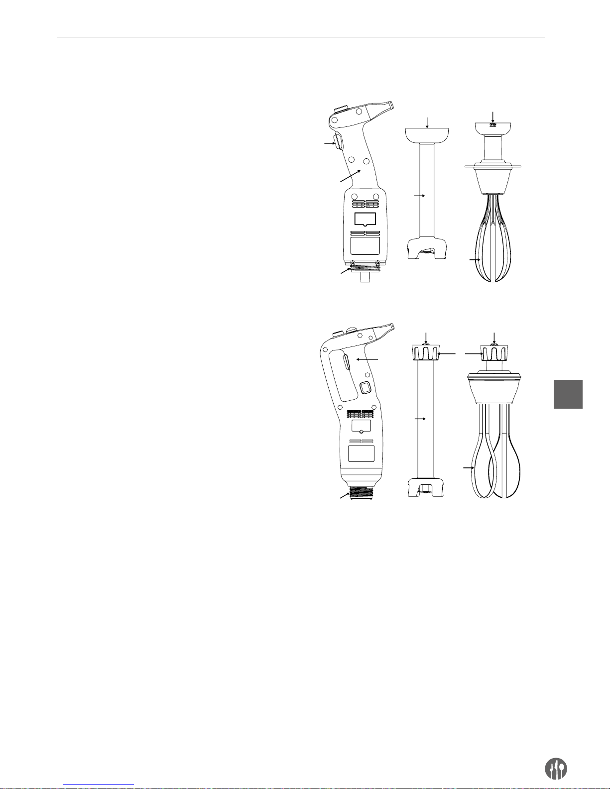
75
FR
Montage/demontage des pieces de l’appareil
Le montage / le démontage des parties de l’appareil doit être effectué quand l’appareil est arrêté et déconnecté du courant.
Montage : Modèle 222140:
1. Ajustez et installez le connecteur (5) du fouet
mixeur (3) ou du fouet battant (6) dans le connecteur (2)
Du corps de l’appareil (1).
2. Serrez précisément le fouet mixeur (3) ou battant
(3) sur le corps (1).
Montage : Modèles 222171 et 222188:
1. Ajustez et installez le connecteur (5) du fouet
mixeur (3) ou battant (6) dans le connecteur (2)
du corps de l’appareil (1). Assurez-vous que la
partie plus étroite du connecteur est ajustée au
côté concave du connecteur du fouet mixeur (3)
ou battant (4).
2. Serrez précisément l’écrou (6) sur le corps (1).
4
3
5
2
6
5
4
2
3
1
6
5 5
1
Pour démonter les accessoires, réalisez les étapes précédentes dans un ordre inverse.
Page 76

76
FR
Instruction de lavage
Avant le nettoyage, débranchez toujours l’appareil
de l’alimentation.
•
Après avoir utilisé le mixeur à main dans un mélange chaud, refroidissez toujours le fouet à l’eau
froide avant d’enlever le fouet. Après avoir fini le
travail, laver immédiatement le fouet pour éviter
l’adhérence des résidus.
•
Ne plongez jamais le moteur ou la poignée dans
l’eau, nettoyez-les avec un chiffon humide ou une
éponge humide.
•
Le nettoyage du fouet mixeur et de l’extrémité :
mettre le fouet et l’extrémité dans un récipient
approprié rempli avec de l’eau propre et mettre
l’appareil en marche pendant quelques secondes.
•
AVERTISSEMENT : après le lavage, séchez toujours complètement les lames pour éviter la formation des taches de rouille.
•
Ne plongez jamais la poignée du fouet battant
dans l’eau, nettoyez-le avec un chiffon humide ou
une éponge humide.
•
Après chaque utilisation, nettoyez l’appareil avec
un détergent ou un désinfectant, n’utilisez jamais
de l’eau de javel pure. Pour nettoyer les parties en
plastique, utilisez les détergents alcalins.
Depannage
Dans le cas de coupure de courant ou de débranchement de l’appareil relâcher le bouton de
marche / d’arrêt (nº 3), vérifiez l’alimentation et
redémarrez l’appareil.
Si l’appareil est arrêté en raison de la surchauffe,
relâchez le bouton d’arrêt / de marche (3) et débranchez l’appareil, attendez quelques minutes
et jusqu’à ce que le moteur refroidisse et la protection contre la surchauffe se réinitialise, ensuite
redémarrez l’appareil.
S’il n’est pas possible de déterminer la cause du
problème : relâchez le bouton d’arrêt / de marche
(3), débranchez l’appareil et vérifiez:
1. la fiche,
2. si les lames sur l’extrémité tournent librement
3. l’état du câble d’alimentation
4. si l’arbre d’entraînement tourne librement en
enlevant l’extrémité et en vérifiant manuellement si l’extrémité de l’arbre tourne
En cas de panne qui n’est pas décrite dans le mode
d’emploi, contactez le revendeur ou renvoyez l’appareil au service.
Page 77
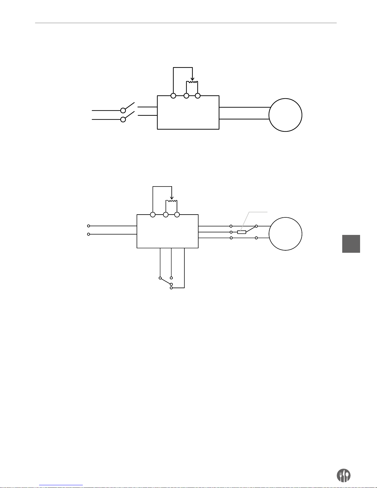
77
FR
Schema electrique
Modèle 222140
AC230V
PC
BM
NO
NO
Potentiomètre
Motor
Interrupteur
Modèle 222171 et 222188
AC230V
PCB
M
NOCom
Nc
Potentiomètre
Motor
Interrupteur
Interrupteur thermique
Page 78
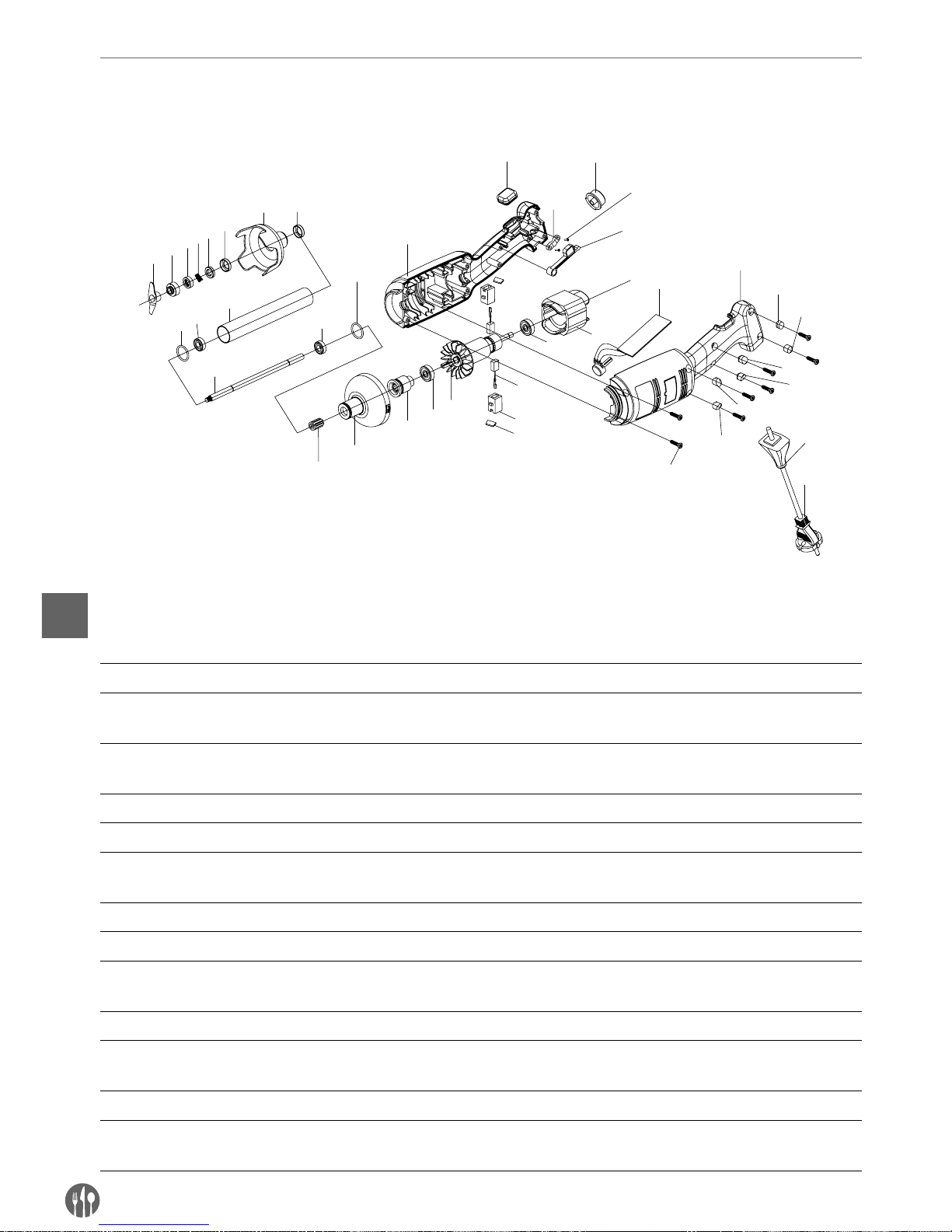
78
FR
Dessin eclate et liste des pieces detachees du modele 222140
Modèle 222140
1
2
4
5
6
7
9
10
11
12
10
9
13
14
15
16
17
19
18
16
20
22
23
25
29-1
31
21
27
24
22
29-2
29-3
29-4
29-5
29-6
30
28
3
26
8
18-1
Liste des pieces - modele 222140 du corps et le fouet mixeur
Nº de
pièce
Nom Nº de
pièce
Nom Nº de
pièce
Nom
1 Lame 14
Boîtier de la tête en plastique
26 Vis de la barre serrage
2 Anneau concave 15 Manchon cannelé 27 Epine de contact de
l’interrupteur
3 Ressort annulaire de
graphite
16 Roulement 28 Vis du boîtier
4 Anneau de graphite 17 Turbine 29-1 Tige filetée 28-1
5 Anneau céramique 18 Prise brosse 29-2 Tige filetée 28-2
6 Manchon céramique
annulaire
18-1 Protection de la brosse 29-3 Tige filetée 28-3
7 Plaque couvre-lame 19 Brosse 29-4 Tige filetée 28-4
8 Manchon de rouelement 20 Stator 29-5 Tige filetée 28-5
9 Anneau d’étanchéité 21 Plaque de commande
de vitesse
29-6 Tige filetée 28-6
10 Roulement W688Z 22 Boîtier gauche et droite 30 Protection du câble
11 Manchon en acier
inoxydable
23
Protection en caoutchouc
contre le verrouillage
31 Câble d’alimentation
12 Manchon 24 Barre de serrage
13 Languette 25 Bouton de réglage
de la vitesse
Page 79
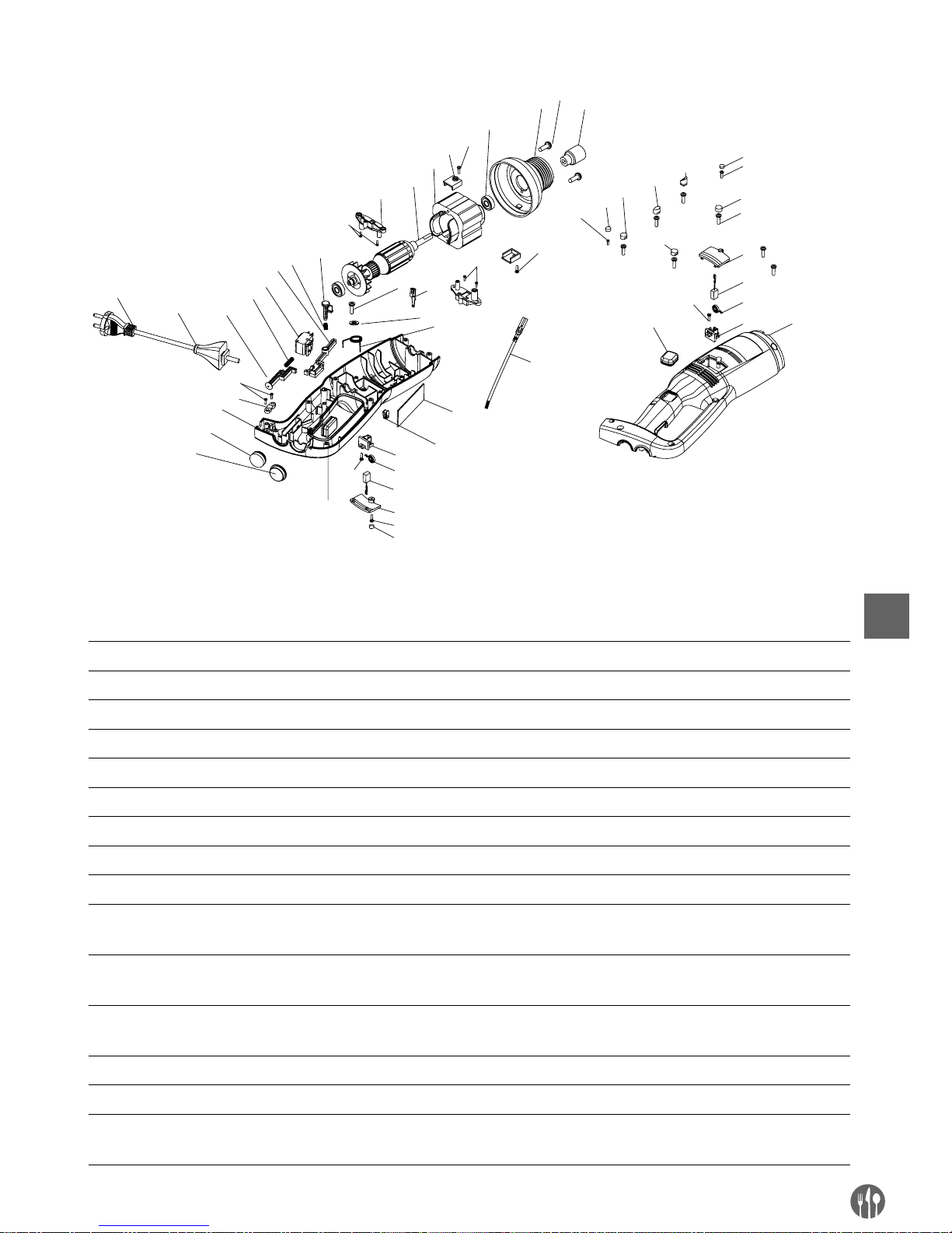
79
FR
Dessin eclate et liste des pieces detachees des modeles 222171 et 222188 (uniquement le corps)
12
13
14
17
18
20
21
23
24
25
26
29
30
31
32
37
5
6
7
8
22
27
33
28
9
4
9
9
2
1-1
28
35
36
34
38
16
15
2
39
1-1
2
4
5
6
7
8
1-3
1-4
1-7
1-5
1-6
3
10
11
19
1-2
9
Liste des pieces des modeles 222171 et 222188 (uniquement le corps)
Nº de
pièce
Nom Nº de
pièce
Nom Nº de
pièce
Nom
1-1 Tige filetée 1 11 Boîtier gauche 26 Protection du câble
1-2 Tige filetée 2 12
Manchon à plusieurs serrages
27 Câble d’alimentation
1-3 Tige filetée 3 13 Tête en aluminium 28 Śruba listwy dociskowej
1-4 Tige filetée 4 14 608 Roulement 29 Barre de serrage
1-5 Tige filetée 5 15 Vis de la plaque du moteur 30 Boîtier droit
1-6 Tige filetée 6 16 Plaque du moteur 31 Bouton en caoutchouc
2 Vis 3*12 CB 17 Stator (en fonction du modèle) 32
Bouton de réglage de la vitesse
3 Vis 3*15 CB 18
Turbine (en fonction du modèle)
33 Logement de l’interrupteur
4 Vis M4*1 19 Prise brosse montée 34 Fiche mâle
5 Protection de la brosse 20 (en fonction du modèle) 35 Plaque de commande de
vitesse
6 Brosse 21 Brin de verrouillage 36
Ressort de l’épine de contact
de l’interrupteur
7 3246 ressort du cylindre
de la brosse
22 Epine de contact
de l’interrupteur
37 Plaque de commande de
vitesse
8 Prise brosse 23 Commutateur 38 Fiche femelle
9 Vis 3*12 CB 24 Ressort du brin 39 Câble de la fiche femelle
10
Protection en caoutchouc
contre le verrouillage
25 Brin
Page 80
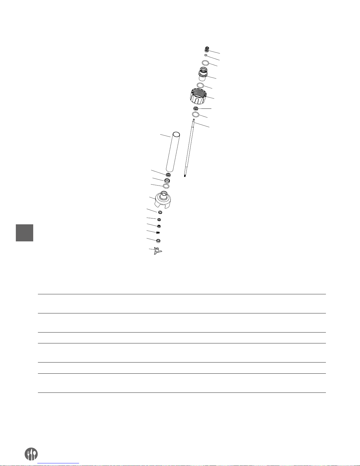
80
FR
FOUETS MIXEURS (OPTION) POUR LES MODELES
1
3
6
7
8
6
9
4
10
11
13
15
16
2
5
12
14
4
4
4
LISTE DES PIECES – FOUETS MIXEURS (OPTIONS): 222218, 222225, 222232, 222249, 222256
Nº de
pièce
Nom Nº de
pièce
Nom Nº de
pièce
Nom
1 Manchon à plusieurs
serrages
7 Manchon de délivrance
(en fonction du modèle)
13 Anneau céramique
2 Anneau d’étanchéité
du manchon
8
Manchon en acier inoxydable
304 (en fonction du modèle)
14 Ressort de graphite
annulaire
3 Manchon de raccordement 9 Manchon de roulement 15 Anneau concave
4 Anneau d’étanchéité du
manchon de raccordement
10 Protection de la lame 16 Lame
5 Manchon de fixation 11 Manchon céramique
6 Roulement 608 12 Anneau céramique
annulaire
Page 81
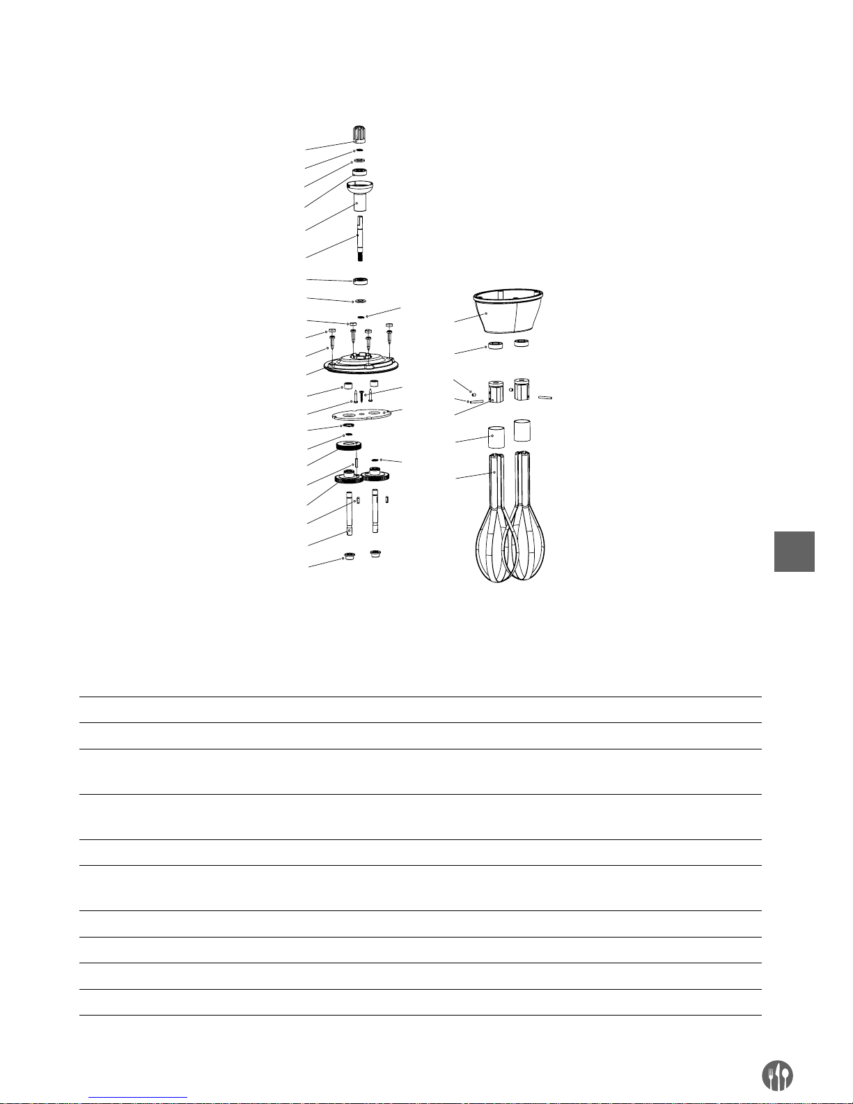
81
FR
FOUET BATTANT (OPTION) DU MODELE 222140
1
2
3
4
5
6
3
4
8
9
11
12
13
2
14
15
16
17
18
19
20
21
22
23
24
25
26
10
7
27
2
28
2
LISTE DES PIECES – FOUET MIXEUR (OPTION) : MODELE 222164
Nº de
pièce
Nom Nº de
pièce
Nom Nº de
pièce
Nom
1 Manchon à plusieurs serrages 11 Roulement à aguilles 21 Joint d’étanchéité d’huile
2 Anneau élastique Ø8 12 Vis 22 Vis M4x5
3 Joint d’étanchéité
du roulement
13 Anneau élastique Ø16 23 Goujon cylindrique
4 Roulement 14 Roulement de l’engrenage à
vis sans fin
24 Barre fixe
5 Manchon de raccordement 15 Goujon cylindrique 25 Anneau en acier
6 Roulement de l’engrenage
à vis sans fin
16 Transmission simple 26 Montant en acier
7 Tige filetée 2 17 Bouton 27 Tamis
8 Tige filetée 1 18 Manchon de délivrance 28 Vis
9 Vis du boîtier 19 Manchon du fouet
10 Couvercle supérieur 20 Couvercle intérieur
Page 82
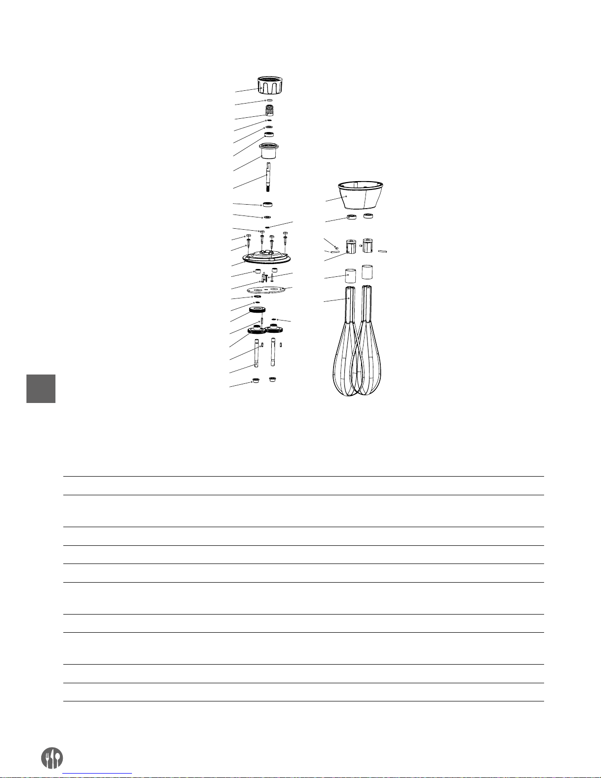
82
FR
FOUETS BATTANTS (OPTION) DES MODELES
3
4
5
6
7
8
5
6
10
11
13
14
15
4
1
6
17
18
19
20
21
22
23
24
25
26
27
28
12
9
29
4
4
30
1
2
LISTE DES PIECES – FOUET MIXEUR (OPTION) : MODELE 222263
Nº de
pièce
Nom Nº de
pièce
Nom Nº de
pièce
Nom
1 Manchon de fixation 11 Vis du boîtier 21 Manchon du fouet
2 Anneau d’étanchéité du
manchon à plusieurs serrages
12 Couvercle supérieur 22 Couvercle intérieur
3 Manchon à plusieurs serrages 13 Roulement à aguilles 23 Joint d’étanchéité d’huile
4 Anneau élastique Ø8 14 Vis 24 Vis M4x5
5 Joint d’étanchéité d’huile 15 Anneau élastique Ø16 25 Goujon cylindrique
6 Roulement 16 Roulement de l’engrenage
à vis sans fin
26 Barre fixe
7 Manchon de raccordement 17 Goujon cylindrique 27 Anneau en acier
8 Roulement de l’engrenage à vis
sans fin
18 Transmission simple 28 Montant en acier
9 Tige filetée 2 19 Bouton 29 Tamis
10 Tige filetée 1 20 Manchon de délivrance 30 Vis
Page 83

83
FR
Garantie
Tout vice ou toute défaillance entraînant un dysfonctionnement de l’appareil qui se déclare dans
les 12 mois suivant la date de l’achat sera éliminé
à titre gratuit ou l’appareil sera remplacé par un
appareil nouveau si le premier a été dûment exploité et entretenu conformément aux termes de
la notice d’exploitation et s’il n‘a pas été indûment
exploité ou de manière non conforme à sa destination. La présente stipulation ne porte pas de préjudice aux autres droits de l’utilisateurs prévus par
les dispositions légales. Dans le cas où l’appareil
est donné à la réparation ou doit être remplacé
dans le cadre de la garantie, il y a lieu de spécifier
le lieu et la date de l’achat de l’appareil et produire
un justificatif nécessaire (par ex. facture ou ticket
de caisse).
Conformément à notre politique d’amélioration
permanente de nos produits, nous nous réservons
le droit d’introduire sans avertissement préalable
des modifications à l’appareil, à l’emballage et aux
caractéristiques techniques précisées dans la documentation.
Retrait de l’exploitation et protection de l’environnement
L’équipement usé et retiré de l’exploitation doit être
valorisé conformément aux dispositions légales et
aux recommandations en vigueur à la date de son
retrait.
Les matériaux d’emballage tels que matières
plastiques et cartons doivent être déposés dans les
bennes prévues pour le type du matériau considéré.
Page 84

84
IT
Gentile cliente,
grazie per aver acquistato questo apparecchio Hendi. Ti invitiamo a leggere queste istruzioni per l’uso con
attenzione prima di collegare l’apparecchio al fine di evitare danni dovuti a uso improprio. Ti invitiamo inoltre a prestare particolare attenzione alle precauzioni di sicurezza.
Precauzioni di sicurezza
• L’uso scorretto e improprio dell’apparecchio possono danneggiare seriamente l’apparecchio e ferire gli utenti.
• Questo dispositivo è destinato esclusivamente per uso commerciale e non può essere
utilizzato per uso domestico.
• L’apparecchio può essere utilizzato solo per lo scopo per cui è stato concepito e proget
tato. Il produttore non è responsabile di eventuali danni provocati da uso scorretto ed
improprio.
• Tenere l’apparecchio e la spina elettrica lontani da acqua ed altri liquidi. Nel caso impro
babile che l’apparecchio cada in acqua, staccare immediatamente la spina dalla presa
e fare ispezionare l’apparecchio da un tecnico certificato. . L’inosservanza delle presenti
istruzioni può dare luogo a situazioni pericolose
• Non provare mai ad aprire l’involucro dell’apparecchio da soli.
• Non inserire oggetti nell’involucro dell’apparecchio.
• Non toccare la presa con le mani bagnate o umide.
• Pericoli di scosse elettriche! Non tentare de riparare l’apparecchio da solo. Eventuali
difetti e malfunzionamenti devono essere rimossi soli da personale qualificato.
• Non usare l’apparecchio danneggiato! L’apparecchio difettoso deve essere immediata
mente scollegato dalla rete e contattare il rivenditore.
• Attenzione: Non immergere parti elettriche in acqua o altri liquidi. Non mettere l’appa
recchio sotto l’acqua corrente.
• Controllare regolarmente se la spina e il cavo di alimentazione non sono danneggiati. La
spina o il cavo danneggiati trasmettere al servizio o alla persona qualificare per riparare,
per evitare eventuali pericoli e lesioni.
• Assicurarsi che il cavo di alimentazione non è in contatto con oggetti appuntiti o caldi. Te
nere il cavo lontano da fiamme libere. Per scollegare la spina dalla presa, tirare sempre
la spina, mai il cavo.
• Proteggere il cavo di alimentazione (o di estensione) per la sconnessione accidentale
dalla presa. Disporre il cavo in modo per evitare lo slittamento accidentale.
• Sorvegliare l’apparecchio continuamente durante l’uso.
• Attenzione! Se la spina è inserita nella presa, l’apparecchio è considerato come collegato.
• Prima di rimuovere la spina dalla presa, spegnere l’apparecchio!
• Non trasportare l’apparecchio tenendo il cavo di alimentazione.
• Non utilizzare qualsiasi accessorio che non è stato fornito con l’apparecchio.
• L’apparecchio deve essere collegato ad una presa con tensione e frequenza indicate sulla
targhetta.
Page 85

85
IT
• Inserire la spina nella presa situata in un punto facilmente accessibile in modo che in
caso di guasto sia possibile scollegare immediatamente l’apparecchio. Per spegnere
completamente l’apparecchio, scollegarlo dalla presa di corrente. Per questo staccare la
spina che si trova sull’estremità del cavo di alimentazione.
• Prima di scollegare la spina, ricordarsi sempre di spegnere l’apparecchio!
• Non usare gli accessori non raccomandati dal produttore. L’uso di accessori non racco
mandati può creare i rischi per l’utente e provocare i danni all’apparecchio. Usare unicamente solo pezzi ed accessori originali.
• L’installazione elettrica deve soddisfare le normative nazionali e locali applicabili. Questo
apparecchio non è destinato all’uso da parte di persone (inclusi i bambini) con capacità
fisiche, sensoriali o mentali ridotte, o senza esperienza e conoscenza.
• Non permettere ai bambini di utilizzare l’apparecchio.
• Tenere l’apparecchio con il cavo fuori dalla portata dei bambini.
• Non permettere ai bambini di giocare con l’apparecchio.
• Scollegare l’apparecchio dalla rete se esso deve essere lasciato incustodito e prima del
montaggio, dello smontaggio o della pulizia.
• Non lasciare l’apparecchio incustodito durante l’utilizzazione.
Regole di sicurezza speciali
• L’apparecchio è concepito esclusivamente per passare, emulsionare e miscelare prodotti
alimentari caldi e freddi per scopi commerciali. L’apparecchio è utilizzato per preparare
zuppe, purè, creme, pasta di marzapane, crema di formaggio, ecc. direttamente nel piat
-
to. L’uso dell’apparecchio per qualsiasi altro scopo può causare danni o lesioni.
• Utilizzare l’apparecchio solo in base alle presenti istruzioni.
• L’apparecchio deve essere utilizzato e mantenuto solo da personale qualificato di cucine
di ristoranti, mense o servizio bar, ecc.
• Quando l’apparecchio è lasciato incustodito e prima del montaggio, smontaggio o pulizia,
scollegarlo dalla presa di corrente togliendo la spina dalla presa di corrente.
• Durante il funzionamento dell’apparecchio non dirigere la lama verso le persone in pros
-
simità.
• Durante il funzionamento dell’apparecchio non toccare la lama o altre parti in movi
mento. Non toccare gli elementi in movimento con le mani o con altri utensili da cucina.
Legare i cappelli.
• Asciugare completamente l’apparecchio e i suoi accessori prima di collegare alla rete di
alimentazione o prima di montare gli accessori.
• Pericolo di lesioni o danni alle mani! Manipolare con attenzione la lama – la lama è molto
tagliente.
• Non aggiungere ingredienti ad un recipiente durante il funzionamento dell’apparecchio.
Attenzione: L’apparecchio deve essere scollegato dalla rete elettrica subito dopo l’uso e
prima di rimuovere o cambiare gli accessori.
Page 86

86
IT
Per installare sul muro il supporto fornito col modello 222133 leggere attentamente le
seguenti istruzioni di sicurezza:
• Per motivi di sicurezza, il montaggio deve essere eseguito da un tecnico qualificato.
• Prima dell’installazione verificare che la parete sia in grado di sostenere il peso dell’ap
-
parecchio.
• Accertarsi che non ci siano fili elettrici, collegamenti per acqua, gas o altri componenti
vicino al luogo di installazione.
• Consultare un appaltatore o uno specialista qualificato se non si è sicuri della struttura
della parete.
• Stringere le viti. Non stringere troppo. Un serraggio eccessivo può danneggiare le viti,
riducendo significativamente la stabilità del montaggio.
• Non lasciare i bambini e gli animali avvicinarsi al luogo del montaggio.
• Avvertimento! Non posizionare sul supporto oggetti diversi dall’apparecchio per evitare
di sovraccaricarlo.
Page 87
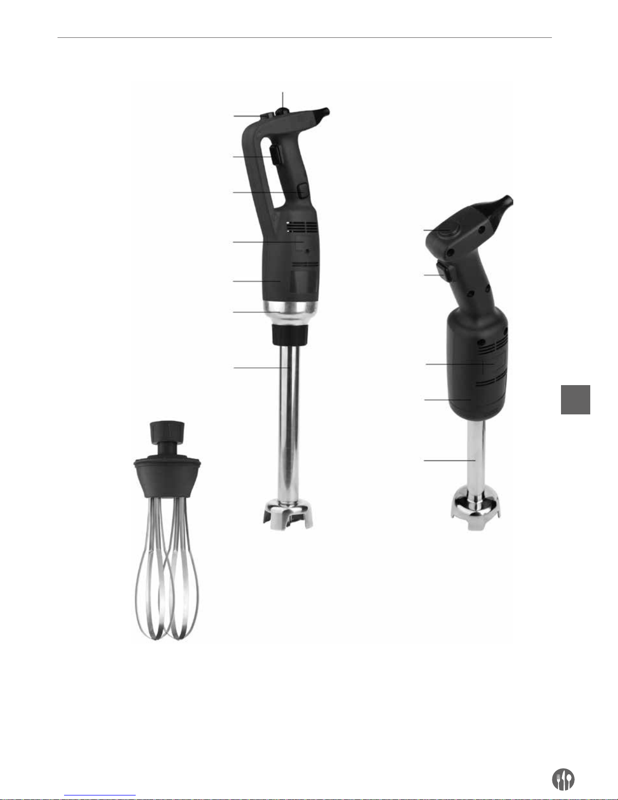
87
IT
Descrizione del prodotto
Pulsante di velocità
variabile (opzione)
Pulsante di velocità
variabile (opzione)
Pulsante di protezione
Pulsante on/off
Pulsante on/off
Pulsante di bloccagio
Protezione di spazzole
Protezione di spazzole
Contenitore di plastica
Contenitore di plastica
Raccordo
Mescolatore
(opzione)
Mescolatore
Frusta (inclusa solo al
modello 222133)
222171 con mescolatore
supplementare (opzione)
222188 con mescolatore
supplementare (opzione)
Modello 222133 con un braccio di
frullatore 400 mm
222140
Page 88
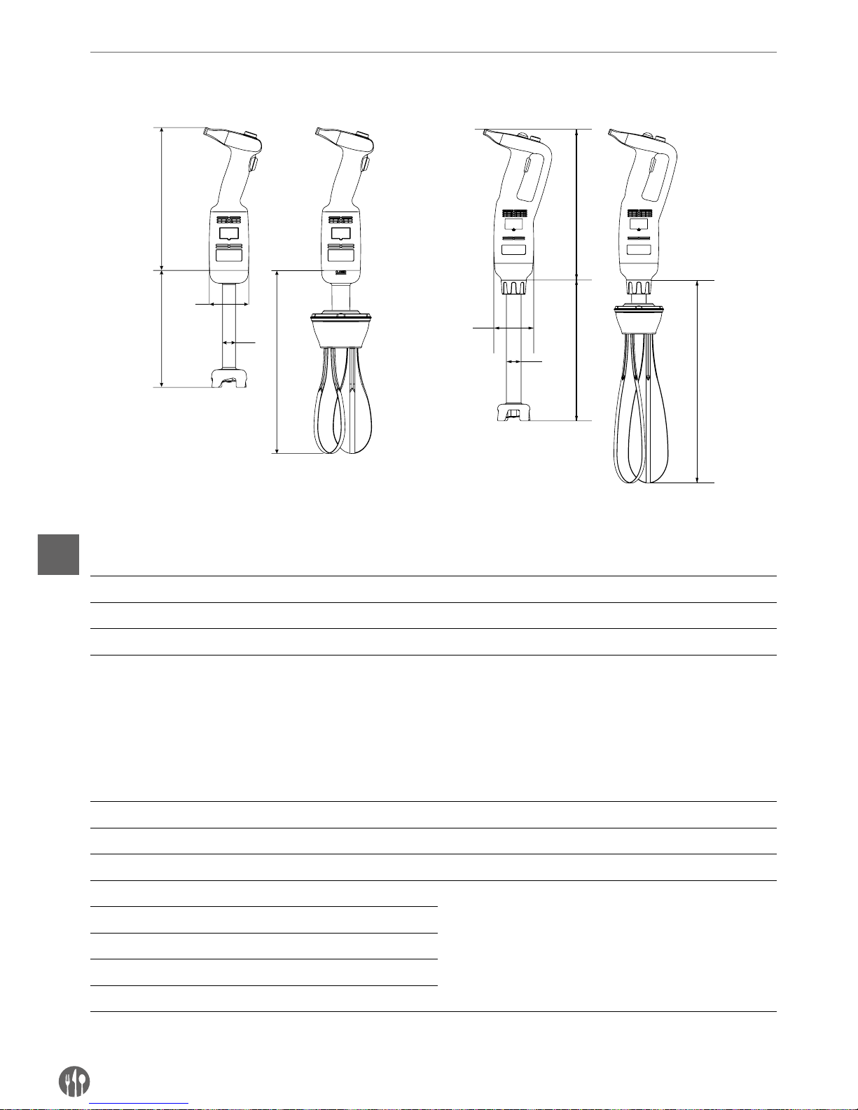
88
IT
Parametri tecnici principali
A
C
B
D
C
D
B
A
C
C
Specificazione tecnica
Codice Tensione Potenza Velocità Peso del corpo senza
mescolatore o frullatoreA(Lunghezza)B(Diameter)
222140 230 V/ 50 Hz 220 W 4,000 ~ 20,000 giri/min. 1,15 kg 304 mm Ø 75 mm
222171 2 30 V/50 H z 350 W 4,000 ~ 16,000 giri/min. 1,76 kg 359 mm Ø 91 mm
222188 230 V/ 50 Hz 500 W 4,000 ~ 16,000 giri/min. 1,98 kg 359 mm Ø 91 mm
Nota: La specificazione tecnica può essere modificata senza preavviso.
Tabella di combinazione con il collegamento del mescolatore e la frusta.
Gli accessori indicato non sono forniti con il prodotto.
Codice Peso C
(Lunghezza)
D
(Diameter)
Descrizione
222164 0,81 kg 185 mm – Frusta per il modello 222140 (opzione)
– 0,46 kg 160 mm Ø 25 mm Mescolatore per il modello 222140 (fornito col prodotto)
222263 0,86 kg 250 mm – Frusta 222171 (opzione) e 222188 (opzione)
222218 0,69 kg 200 mm Ø 35 mm
Mescolatore per i modelli 222171 (opzione)
e 222188 (opzione)
222225 0,82 kg 250 mm Ø 35 mm
222232 1,02 kg 300 mm Ø 35 mm
222249 1,28 kg 400 mm Ø 35 mm
222256 1,56 kg 500 mm Ø 35 mm
Nota: Modello 222133 – il set - comprende 222171 + 222249 + 222263 + supporto murale + kit di montaggio (2
set di viti di fissaggio, rondelle e tasselli a espansione).
Modello: 222140 Modelli: 222171/222188
Page 89

89
IT
Introduzione
•
Leggere attentamente le istruzioni d’uso. Le
istruzioni contengono le informazioni importanti
relative alla sicurezza dell’utente nonché i consigli su come utilizzare l’apparecchio e sulla sua
manutenzione.
•
L’apparecchio è progettato per l’uso professionale
in gelaterie, ristoranti, cucine negli alberghi per
preparare gelato, zuppe di verdure, purè salse,
ripieno, maionese, pasta di pomodoro, pesto ecc.
•
Per approfittare completamente delle possibilità
dell’apparecchio, è necessario leggere attentamente le informazioni sulle sue funzioni.
•
La manutenzione consiste in realizzare semplici
attività che possono eseguite dall’operatore.
•
Per garantire lunga durata dell’apparecchio e ridurre i costi del funzionamento si prega di seguire
le istruzioni.
•
L’apparecchio è stato progettato da produttore in
modo che garantisce la sicurezza dell’utilizzo.
Lo smontaggio delle protezioni installate dal produttore ridurrà seriamente la sicurezza dell’apparecchiatura.
•
Per garantire la sicurezza, è necessario seguire
le istruzioni per l’installazione e la connessione
dell’apparecchio alla rete.
•
L’apparecchio deve essere installato in un ambiente di lavoro privo di fattori corrosivi.
•
La zona di installazione non può essere potenzialmente esplosiva.
•
Utilizzare solo i PEZZI DI RICAMBIO ORIGINALI.
•
Le presenti istruzioni d’uso costituiscono parte
integrale dell’apparecchio e devono essere messe in un luogo sicuro. Le funzioni, le specifiche e
le figure presentate in questo documento sono la
proprietà esclusiva del costruttore.
•
Le funzioni dell’apparecchio consentono di preparare i seguenti tipi di cibo nel più breve tempo
possibile: passate di verdure dense, zuppe, purè
di patate, creme, dolci, maionese, pasta di mandorle, formaggi cremosi ecc.
Preparazione al montaggio del supporto su parete (solo il modello 222133)
Prima del montaggio: Controllare che il supporto murale non presenti danni e che i kit di montaggio sono
completi (2 set di viti di fissaggio, rondelle e tasselli a espansione). Se il supporto murale è danneggiato o
incompleto, NON INSTALLARE.
Attenzione:
• Consultare un appaltatore o uno specialista
qualificato se non si è sicuri della struttura della
parete. Questo per garantire il corretto e sicuro
assemblaggio dell’apparecchio.
• Per motivi di sicurezza, il montaggio deve essere
eseguito da un tecnico qualificato.
• La distanza tra i fori per le viti di montaggio
dovrebbe essere di circa 217 mm. Prima di iniziare il lavoro, ordinare il sito di installazione.
• Informazioni importanti: prima del montaggio,
assicurarsi che tutti gli utensili siano disponibili, come un cacciavite, un trapano elettrico, un
misurino, una matita (non forniti con l’apparecchio).
• Il supporto deve essere fissato sicuramente al
muro con due viti di fissaggio e tasselli a espansione.
• Si deve ricordare che nell’area di assemblaggio
ci possono essere elementi come per esempio
condotti, cavi elettrici e tubi. Prestare particolare
attenzione durante il montaggio.
Page 90
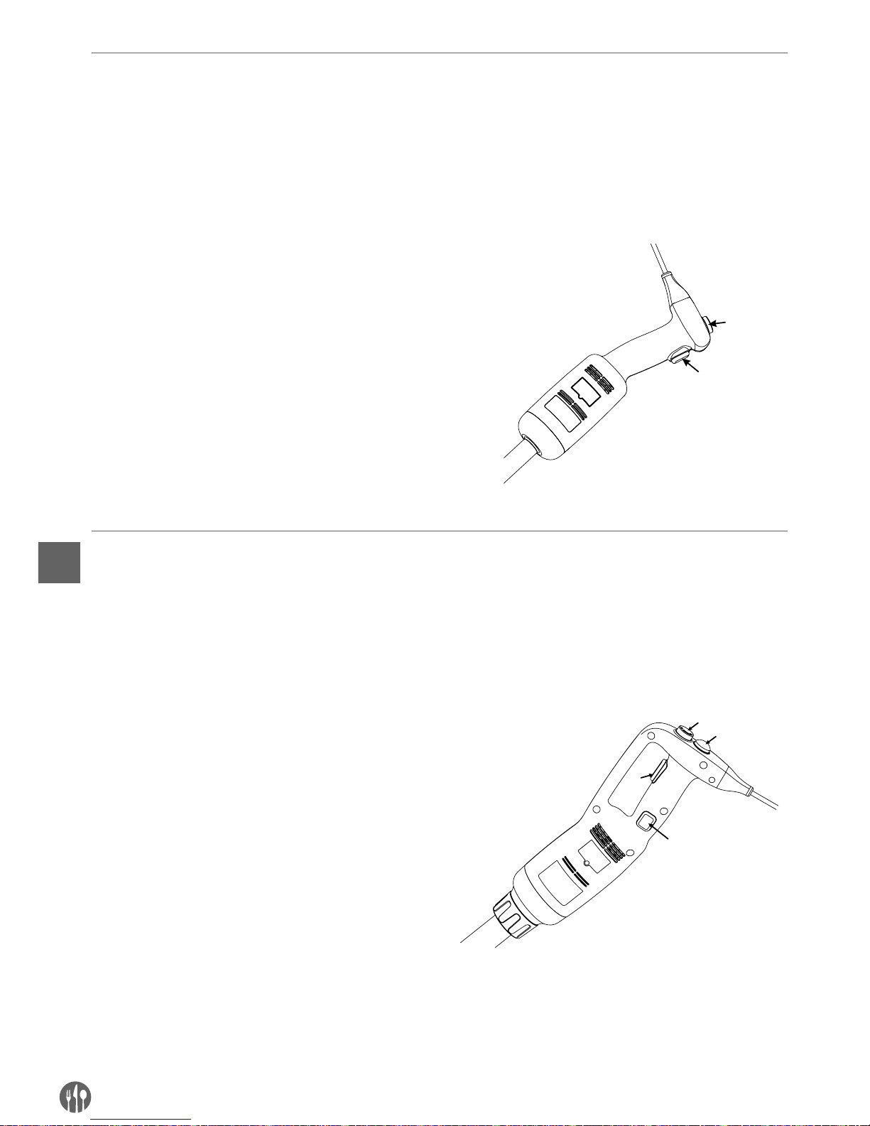
90
IT
Istruzioni d’uso
ISTRUZIONI D’USO (MODELLO 222140):
NOTA! Prima di collegare l’apparecchio a una fonte di alimentazione, assicurarsi che le specifiche dell’appa-
recchio sulla targhetta corrispondono ai parametri locali.
NOTA! Il modello 222140 non possiede la funzione di bloccaggio che permette il funzionamento ininterrotto
dell’apparecchio.
USO DELL’APPARECCHIO:
1. Prima di montare le parti, assicurarsi che l’apparecchio è collegato a una fonte di alimentazione.
2. Collegare il mescolatore / la frusta al corpo.
3. Collegare l’apparecchio a una fonte di alimentazione.
4. Verificare che il pulsante on/off è disattivato (posizione piatta).
5. Poi premere il pulsante on/off. L’apparecchio si
avvia. FARE ATTENZIONE!
6. Per arrestare il frullatore, rilasciare il pulsante
on/off
1
2
Istruzioni d’uso (modelli: 222171 e 222188):
NOTA! Prima di collegare l’apparecchio a una fonte di alimentazione, assicurarsi che le specifiche dell’appa-
recchio sulla targhetta corrispondono ai parametri locali.
NOTA! Il modelli 222171 e 222188 possiedono la funzione di bloccaggio che permette il funzionamento ininterrotto dell’apparecchio.
AVVIO E ARRESTO DELL’APPARECCHIO
1. Prima di montare le parti, assicurarsi che l’apparecchio è collegato a una fonte di alimentazione.
2. Collegare il mescolatore / la frusta al corpo.
3. Collegare l’apparecchio a una fonte di alimentazione.
4. Verificare che il pulsante on/off (3) è disattivato
(posizione piatta)..
5. Prima premere e tenere premuto il pulsante di
protezione (1).
6. Poi premere e tenere premuto il pulsante on/
off (3) contemporaneamente con il pulsante di
protezione. L’apparecchio si avvia. FARE ATTENZIONE!
7. Per arrestare il funzionamento dell’apparecchio,
rilasciare il pulsante on/off (3) e il pulsante di
protezione (1).
1
2
3
4
Page 91

91
IT
LAVORO CONTINUO:
Seguire i punti 1-6, e poi:
•
Tenendo premuto il pulsante on/off (3), spostare
il dito dal pulsante di protezione (1) sul pulsante
di bloccaggio (4).
•
Rilasciare il pulsante on/off (3) e il pulsante di
protezione (4) – l’apparecchio si avvia automaticamente.
•
Per arrestare l’apparecchio, premere e rilasciare
il pulsante on/off. (3).
Cambio di velocita’ (modelli: 222140, 222171 e 222188)
Seguire i punti 1-6, e poi:
•
Modificare la velocità del motore girando la manopola di velocità (2) verso la velocità massima o
minima (secondo la sua discrezione). Se si utiliz-
za la frusta, si consiglia di avviare l’apparecchio
a bassa velocità. Grazie al sistema automatico di
regolazione della velocità, la velocità selezionata
rimane costante anche in caso di cambiamento di
consistenza di ingredienti misti.
ATTENZIONE :
Funzione mescolatore: Per garantire un miglio-
re controllo, si consiglia di tenere la maniglia del
frullatore e la parte inferiore del corpo del motore. Si raccomanda anche inclinare leggermente il
frullatore perché l’estremità del mescolatore non
tocchi il fondo del piatto. Controllare sempre se il
mescolatore è immerso abbastanza in profondità
per evitare schizzi e la penetrazione del liquido attraverso i fori di ventilazione del motore. Per garantire l’efficienza massima, immergere due terzi
del mescolatore nella miscela.
Funzione frusta: È anche possibile tenere l’apparecchio con una mano e poi, con la seconda mano,
tenere la ciotola. Si raccomanda spostare la frusta
intorno la ciotola per garantire la compattazione
uniforme della massa. Fare attenzione a non toc-
care i lati della ciotola con la frusta. Per garantire
l’efficienza massima, immergere almeno un quinto
della lunghezza della frusta nella miscela. Non immergere la maniglia.
Page 92
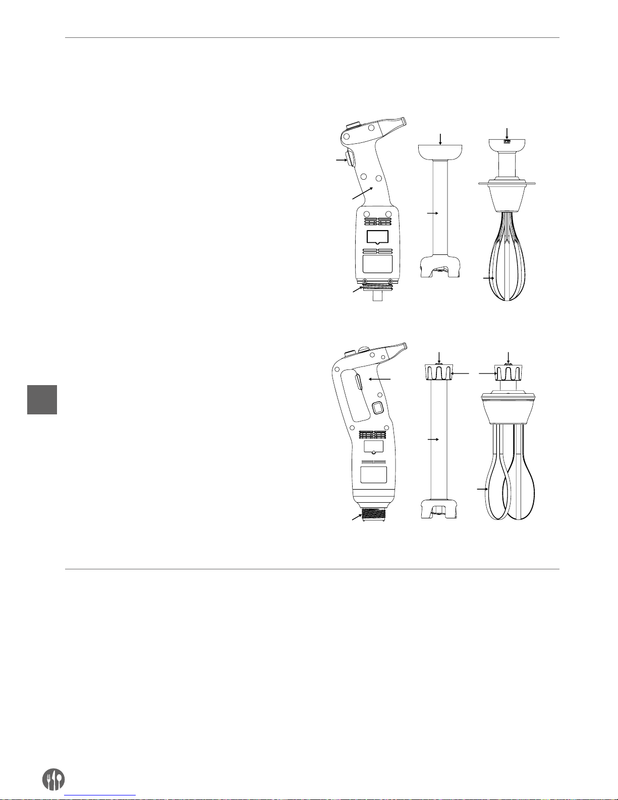
92
IT
Montaggio/smontaggio delle parti dell’apparecchio
Il montaggio / lo smontaggio delle parti dell’apparecchio deve essere eseguito con l’apparecchio spento e
scollegato dalla rete elettrica.
Montaggio: Modello 222140:
1. Regolare e mettere il raccordo (5) del mescolatore (3) o della frusta (6) nel raccordo (2) del
corpo dell’apparecchio (1).
2. Stringere esattamente il mescolatore (3) o la frusta (6) al corpo (1).
Montaggio: Modelli 222171 e 222188:
1. Regolare e mettere il raccordo (5) del mescolatore (3) o della frusta (4) nel raccordo (2) del corpo dell’apparecchio (1). Assicurarsi che la parte
più stretta del raccordo dell’apparecchio è bene
aggiustata alla parte concava del raccordo del
mescolatore (3) o della frusta (4).
2. Stringere esattamente il dado (6) al corpo (1).
4
3
5
2
6
5
4
2
3
1
6
5 5
1
Per smontare gli accessori, eseguire la procedura in ordine inverso.
Istruzioni di lavaggio
Prima della pulizia, scollegare sempre l’apparecchio dalla fonte di alimentazione.
• Dopo aver utilizzato il frullatore manuale in una
miscela calda, raffreddare il braccio in acqua
fredda prima di rimuovere l’estremità del braccio.
Dopo aver finito il lavoro, lavare immediatamente
il braccio per impedire l’adesione di residui.
• Mai immergere il motore o la maniglia in acqua,
pulire con un panno umido o una spugna umida.
• Pulizia del mescolatore e dell’estremità: mette-
re il mescolatore e l’estremità in un contenitore
adatto riempito di acqua pulita e accendere l’apparecchio per alcuni secondi.
• AVVERTIMENTO: Dopo il lavaggio sempre asciugare accuratamente le lame per prevenire la formazione di macchie di ruggine.
• Mai immergere la maniglia della frusta in acqua,
pulire con un panno umido o una spugna.
• Dopo ogni utilizzo pulire l’apparecchio con un
detergente o disinfettante, non utilizzare candeggiante puro. Per la pulizia delle parti di plastica
non utilizzare detergenti alcalini.
Page 93
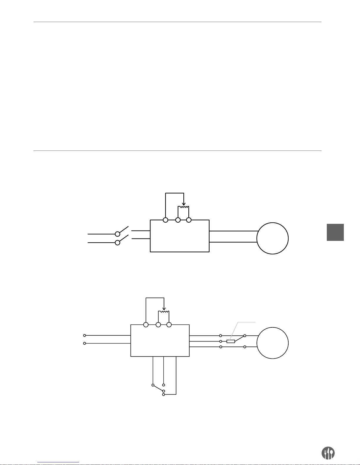
93
IT
Risoluzione dei problemi
In caso di interruzione di alimentazione o disconnessione dell’apparecchio, rilasciare il pulsante
on/off (3) e controllare l’alimentazione, poi riavviare
l’apparecchio.
Se l’apparecchio è spento a causa di un surriscaldamento, rilasciare il pulsante on/off (3), scollegare il cavo di alimentazione, attendere alcuni minuti
fino a quando il motore si è raffreddato e la protezione contro il surriscaldamento si ripristina, poi
avviare l’apparecchio.
Se non è possibile determinare la causa del problema: rilasciare il pulsante on/off (3) scollegare
l’apparecchio di alimentazione e controllare:
1. la spina,
2. se le lame nell’estremità ruotano liberamente,
3. lo stato del cavo di alimentazione,
4. se l’albero di motore ruota liberamente. Per
questo, togliere l’estremità di calice e controllare manualmente se l’estremità dell’albero si
muove.
In caso di difetti non descritti nelle presenti istruzioni, prendere un contatto con il venditore o trasmettere l’apparecchio ad un centro di servizio.
Schema elettrico
Modello 222140
AC230V
PC
BM
NO
NO
Potenziometro
Motorer
Interruttore
Modelli 222171 e 222188
AC230V
PCB
M
NOCom
Nc
Potenziometro
Motorer
Interruttore
Interruttore termico
Page 94
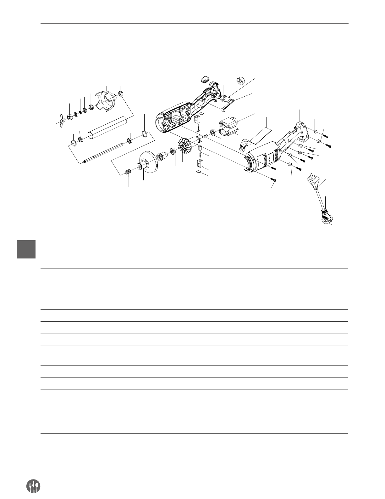
94
IT
Disegno esploso e elenco dei pezzi del modello 222140
Modello 222140
1
2
4
5
6
7
9
10
11
12
10
9
13
14
15
16
17
19
18
16
20
22
23
25
29-1
31
21
27
24
22
29-2
29-3
29-4
29-5
29-6
30
28
3
26
8
18-1
Elenco dei pezzi - modello 222140 corpo e mescolatore
N. del
pezzo
Nome N. del
pezzo
Nome N. del
pezzo
Nome
1 Lama 14 Contenitore della testa
di plastica
26 Vite della barra
di serratura
2 Anello concavo 15 Mandrino scanalato 27 Stelo di contatto
dell’interruttore
3 Molla annullare di grafite 16 Cuscinetto 28 Vite del contenitore
4 Anello di grafite 17 Rotore 2 9-1 Alberino filettato 28-1
5 Anello ceramico 18 Portaspazzole 29-2 Alberino filettato 28-2
6 Mandrino annullare
ceramico
18-1 Protezione della spazzola 29-3 Alberino filettato 28-3
7 Protezione della lama 19 Spazzola 29-4 Alberino filettato 28-4
8 Mandrino di cuscinetto 20 Statore 29-5 Alberino filettato 28-5
9 Anello di tenuta 21
Piastra di controllo di velocità
29-6 Alberino filettato 28-6
10 Cuscinetto W688Z 22 Contenitore destro e sinistro 30 Protezione del cavo
11 Mandrino di acciaio inox 23
Protezione di gomma contro
bloccaggio
31 Cavo di alimentazione
12 Mandrino di distribuzione 24 Barra di serratura
13 Linguetta 25 Pulsante di velocità
Page 95
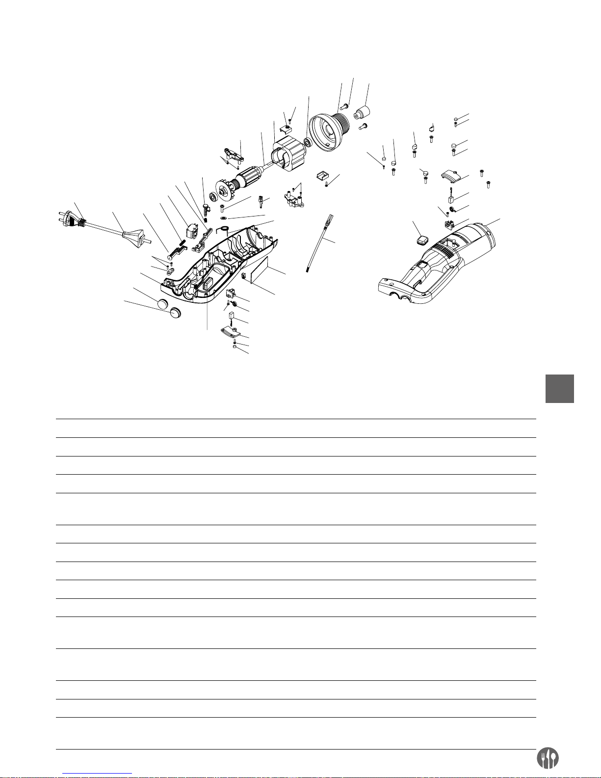
95
IT
Disegno esploso e elenco dei pezzi dei modelli 222171 e 222188 (unicamente corpo)
12
13
14
17
18
20
21
23
24
25
26
29
30
31
32
37
5
6
7
8
22
27
33
28
9
4
9
9
2
1-1
28
35
36
34
38
16
15
2
39
1-1
2
4
5
6
7
8
1-3
1-4
1-7
1-5
1-6
3
10
11
19
1-2
9
Elenco dei pezzi dei modelli 222171 e 222188 (unicamente corpo)
N. del
pezzo
Nome N. del
pezzo
Nome N. del
pezzo
Nome
1-1 Alberino filettato 1 11 Contenitore sinistro 26 Protezione del cavo
1-2 Alberino filettato 2 12 Mandrino scanalato 27 Cavo di alimentazione
1-3 Alberino filettato 3 13 Testa di alluminio 28 Vite della barra di serratura
1-4 Alberino filettato 4 14 608 Cuscinetto 29 Barra di serratura
1-5 Alberino filettato 5 15 Vite della piastra di fissaggio
del motore
30 Contenitore destro
1-6 Alberino filettato 6 16 Piastra di fissaggio del motore 31 Pulsante di gomma
2 Vite 3*12 CB 17 Statore (secondo il modello) 32 Pulsante di velocità
3 Vite 3*15 CB 18 Rotore (secondo il modello) 33 Presa dell’interruttore
4 Vite M4*1 19 Portaspazzole installato 34 Spina maschio
5 Protezione della spazzola 20 (secondo il modello) 35
Piastra di controllo di velocità
6 Spazzola 21 Perno di bloccaggio 36
Molla di stelo di contatto
dell’interruttore
7 3246 Molla del cilindro
della spazzola
22 Stelo di contatto
dell’interruttore
37 Piastra di controllo
di velocità
8 Portaspazzole 23 Interruttore 38 Spina femmina
9 Vite 3*12 CB 24 Molla di perno 39 Cavo della spina femmina
10
Protezione di gomma
contro bloccaggio
25 Perno
Page 96
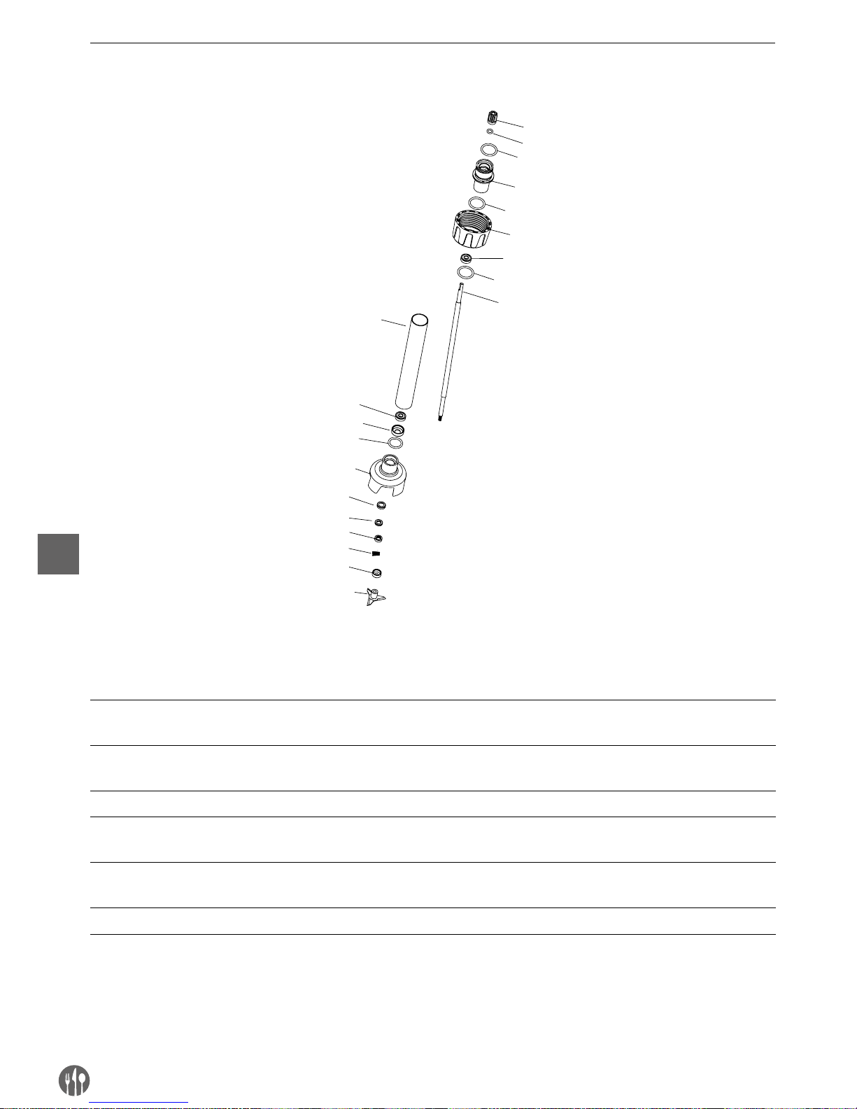
96
IT
Mescolatori (opzione) dei modelli
1
3
6
7
8
6
9
4
10
11
13
15
16
2
5
12
14
4
4
4
Elenco dei pezzi - mescolatori (opzione): 222218, 222225, 222232, 222249, 222256
N. del
pezzo
Nome N. del
pezzo
Nome N. del
pezzo
Nome
1 Mandrino scanalato 7 Mandrino di distribuzione
(secondo il modello)
13 Anello di grafite
2 Anello di tenuta del
mandrino scanalato
8
Mandrino di acciaio inox 304
(secondo il modello)
14 Molla annullare di grafite
3 Mandrino di collegamento 9 Mandrino di cuscinetto 15 Anello concavo
4 Anello di tenuta del
mandrino di collegamento
10 Protezione della lama 16 Lama
5 Mandrino di fissaggio 11 Mandrino annullare
ceramico
6 Cuscinetto 608 12 Anello ceramico
Page 97
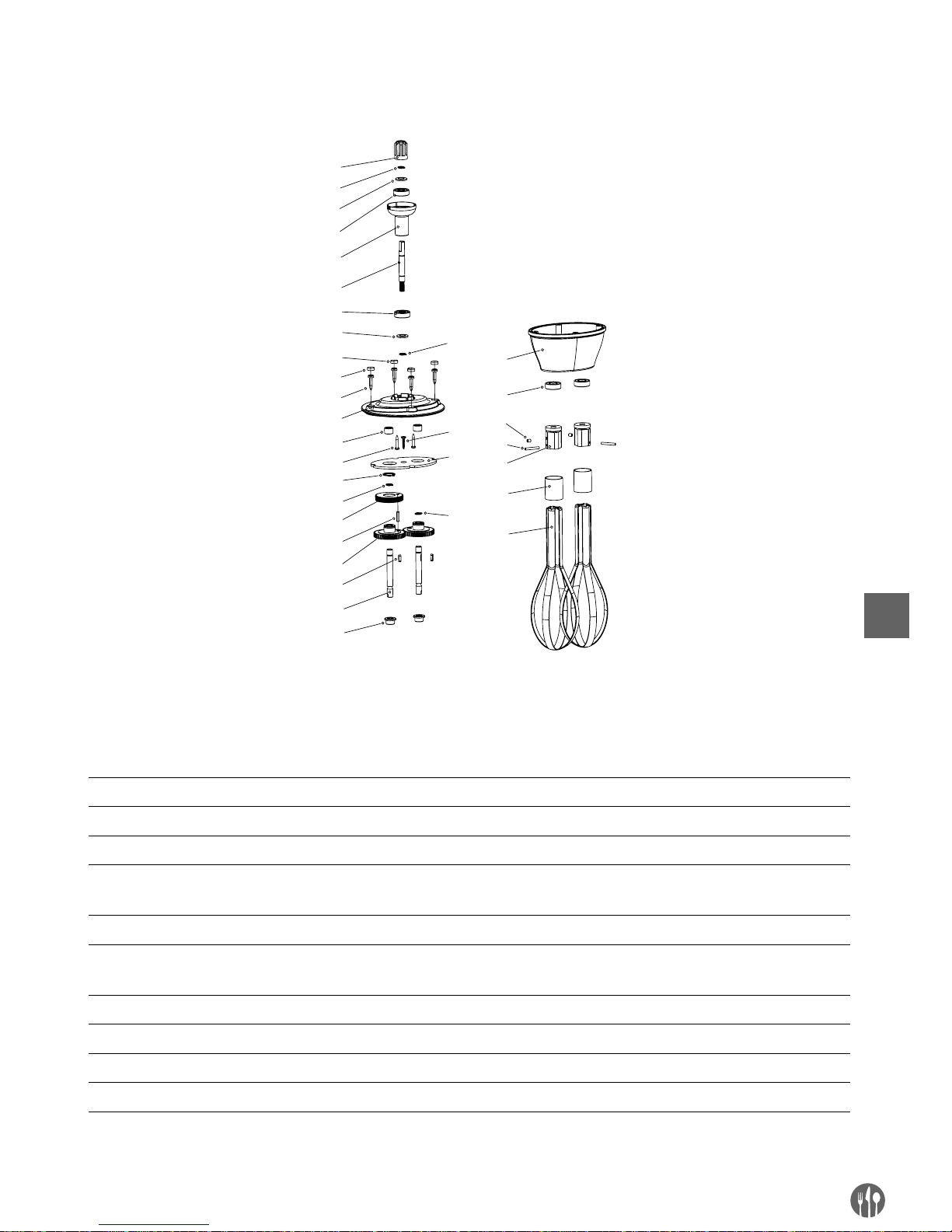
97
IT
Frusta (opzione) per il modello 222140
1
2
3
4
5
6
3
4
8
9
11
12
13
2
14
15
16
17
18
19
20
21
22
23
24
25
26
10
7
27
2
28
2
Elenco dei pezzi - mescolatore (opzione): modello 222164
N. del
pezzo
Nome N. del
pezzo
Nome N. del
pezzo
Nome
1 Mandrino scanalato 11 Cuscinetto ad aghi 21 Guarnizione di olio
2 Anello elastico Ø8 12 Vite 22 Vite M4x5
3 Guarnizione del cuscinetto 13 Anello elastico Ø16 23 Bullone cilindrico
4 Cuscinetto 14 Cuscinetto di ingranaggio
a vite senza fine
24 Barra fissata
5 Mandrino di collegamento 15 Bullone cilindrico 25 Anello di acciaio
6 Cuscinetto di ingranaggio
a vite senza fine
16 Trasmissione semplice 26 Montante di acciaio
7 Alberino filettato 2 17 Pulsante 27 Passino
8 Alberino filettato 1 18 Mandrino di distribuzione 28 Vite
9 Vite del contenitore 19 Mandrino del mescolatore
10 Coperchio inferiore 20 Coperchio inferiore
Page 98
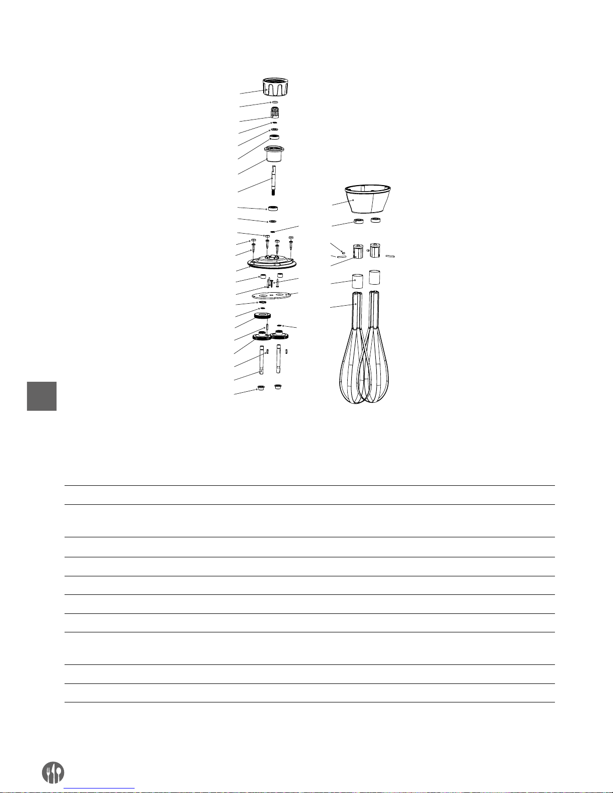
98
IT
Fruste (opzione) dei modelli
3
4
5
6
7
8
5
6
10
11
13
14
15
4
1
6
17
18
19
20
21
22
23
24
25
26
27
28
12
9
29
4
4
30
1
2
Elenco dei pezzi - mescolatori (opzione): modello 222263
N. del
pezzo
Nome N. del
pezzo
Nome N. del
pezzo
Nome
1 Mandrino di fissaggio 11 Vite del coperchio 21 Mandrino del mescolatore
2 Anello di tenuta del
mandrino scanalato
12 Coperchio superiore 22 Coperchio inferiore
3 Mandrino scanalato 13 Cuscinetto ad aghi 23 Guarnizione di olio
4 Anello elastico Ø8 14 Vite 24 Vite M4x5
5 Mandrino scanalato 15 Vite Ø16 25 Bullone cilindrico
6 Cuscinetto 16 Vite 26 Barra fissata
7 Cuscinetto 17 Bullone cilindrico 27 Anello di acciaio
8 Cuscinetto di ingranaggio
a vite senza fine
18 Trasmissione semplice 28 Montante di acciaio
9 Alberino filettato 2 19 Pulsante 29 Passino
10 Alberino filettato 1 20 Mandrino di distribuzione 30 Vite
Page 99

99
IT
Garanzia
Qualsiasi difetto che influenza la funzionalità del
dispositivo che compaia entro un anno dall’acquisto sarà corretto a titolo interamente gratuito o con
la sostituzione del prodotto che è stato utilizzato
e sottoposto a manutenzione corretta seguendo
le istruzioni, senza alcuna violazione. I diritti legali
del cliente non sono assolutamente modificati. Nel
caso in cui l’intervento di manutenzione o sostitu-
zione sia previsto nel periodo di validità della garanzia, precisare dove e quando si è acquistato il
prodotto, possibilmente allegando lo scontrino.
In linea con la nostra politica di sviluppo continuo
dei prodotti, ci riserviamo il diritto di modificare il
prodotto, l’imballo e le specifiche di documentazione, senza notifica alcuna.
Smaltimento & Ambiente
Alla fine della vita utile del dispositivo, smaltire
conformemente alle normative e linee guida applicabili.
Eliminare i materiali di imballaggio, quali plastica e
cartone, negli specifici contenitori.
Page 100

100
RO
Stimate client,
Vă mulumim pentru achiziionarea acestui aparat Hendi. Vă rugăm să citii cu atenia acest manual înainte
de a conecta aparatul pentru evitarea defectării ca urmare a utilizării incorecte. Acordai o atenie deosebită
regulilor de sigurană.
Reguli de sigurană
• Operarea incorectă şi utilizarea necorespunzătoare a aparatului poate avaria grav aparatul şi poate cauza răni oamenilor.
• Aparatul este utilizat exclusiv în scopuri comerciale și nu trebuie folosit pentru uz casnic.
• Aparatul poate fi folosit doar în scopul pentru care a fost proiectat. Producătorul nu este
răspunzător pentru orice avariere cauzată operării incorecte şi a utilizării necorespun
-
zătoare.
• Asiguraţi-vă că aparatul şi ştecherul nu intră în contact cu apă sau alte lichide. În cazul
în care aparatul este scăpat în apă, scoateţi imediat ştecherul din priză şi un tehnician
autorizat trebuie să-l verifice. Dacă nu respectaţi aceste instrucţiuni, acest lucru poate
cauza situaţii care vă pot pune viaţa în pericol.
• Nu incercati sa deschideti singuri carcasa aparatului.
• Nu introduceţi nici un fel de obiecte în carcasa aparatului.
• Nu atingeţi ştecherul cu mâinile ude sau umede.
• Pericol de electrocutare! Nu încercați să reparați singur/ă aparatul. În cazul unei defec
-
țiuni, reparațiile vor fi efectuate întotdeauna numai de personal calificat.
• Nu utilizai niciodată un aparat defect! Deconectați aparatul de la priza electrică și con
-
tactați distribuitorul în cazul unei defecțiuni.
• Avertisment! Nu scufundați părțile electrice ale aparatului în apă sau în alte lichide. Nu
țineți niciodată aparatul sub jet de apă.
• Verificați în mod regulat ștecărul și cablul pentru a vă asigura că nu sunt deteriorate. În
cazul în care ștecărul sau cablul de alimentare este deteriorat, acesta trebuie înlocuit de
agentul de service sau de alt personal calificat similar pentru a evita orice pericol
• Cablul nu trebuie să intre în contact cu obiecte ascuțite sau fierbinți și trebuie păstrat
departe de foc. Pentru a scoate ștecărul din priză, trageți întotdeauna de ștecăr, nu de
cablu.
• Asigurați-vă că nimeni nu poate trage din greșeală cablul (sau prelungitorul) și că nimeni
nu se poate împiedica de el.
• Supravegheați întotdeauna aparatul atunci când este în funcțiune.
• Avertisment! Atât timp cât ștecărul este în priză, aparatul este conectat la sursa de elec
-
tricitate.
• Opriți aparatul înainte de a scoate ștecărul din priză.
• Nu cărați niciodată aparatul ținându-l de cablu.
• Nu utilizați dispozitive suplimentare care nu sunt livrate împreună cu aparatul.
• Conectați aparatul doar la prize electrice cu intensitatea și frecvența electrice menționa
-
te pe eticheta aparatului.
 Loading...