

Page 1
Introduction
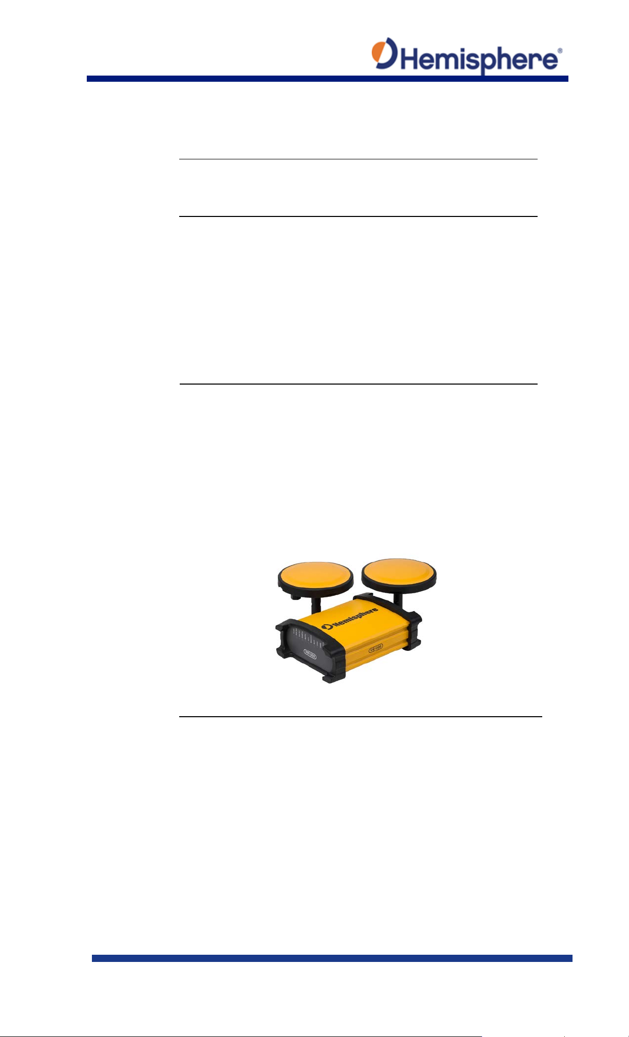
Created by Hemisphere GNSS, this QRG provides information and
the steps to follow to set up your Vector VR1000 GNSS Receiver.
VR1000 key
Key features of the VR1000 include:
Heading accuracy up to .01°
Mounting
When considering where to mount the VR1000, consider the
Figure 1: VR1000 GNSS Receiver
Vector VR1000 GNSS Receiver Quick Reference Guide (QRG)
features
• High-precision positioning in Athena RTK, Atlas L-band, and SBAS
• Athena technology for improved RTK performance, especially
with GLONASS, Galileo, and BeiDou
• Atlas* L-band technology providing highly accurate corrections
over the air (*Requires the purchase of a subscription)
• Heave of 30 cm RMS (DGNSS), 10 cm (RTK)
• Pitch and roll < 1° RMS
•
following satellite reception recommendations:
• Ensure cable length is adequate to route into the machine to
reach a breakout box or terminal strip.
• Do not mount the receiver where environmental conditions
exceed those specified in the VR1000 Technical Specifications of
this document.
• Route cables away from any potential source of mechanical
damage.
875-0422-10 Vector VR1000 QRG Rev A1
March 29, 2019 Page 1 of 36
Continued on next page
Page 2
Environmental
Hemisphere Vector GNSS Receivers are designed to withstand
Humidity: IEC 16750-4:2010 Section 5.6 Humid heat, cyclic test
Mounting
The VR1000 outputs heading, pitch, and roll readings regardless of
heading, pitch, and roll values.
Parallel
Install the GNSS antennas parallel to, and along the centerline of the
measurement if the receiver is not installed in a horizontal plane.
Perpendicular
Install the GNSS antennas perpendicular to the centerline of the
measurement if the receiver is not installed in a horizontal plane.
Vector VR1000 GNSS Receiver Quick Reference Guide (QRG),
Continued
considerations
orientation
orientation
harsh environmental conditions; however, adhere to the following
limits when storing and using the VR1000:
• Operating temperature: -40°C to +70°C (-40°F to +158°F)
• Storage temperature: -40°C to +85°C (-40°F to +185°F)
•
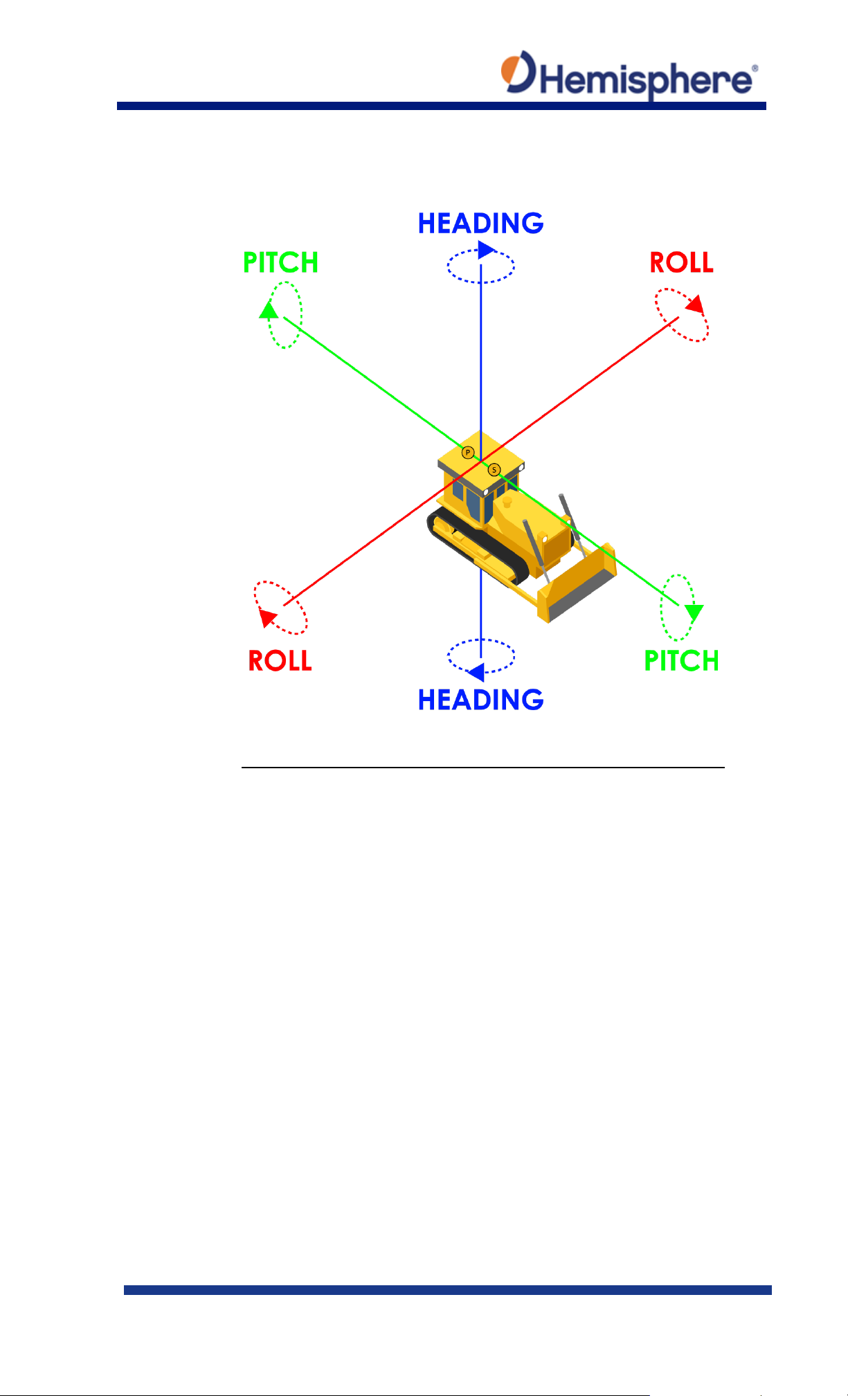
the orientation of the VR1000. The relation of the antennas to the
machine’s axis determines if you need to enter a heading, pitch, or
roll bias. The primary antenna is used for positioning and the
primary and secondary antennas, working in conjunction, output
axis of the machine. This provides a true heading. In this
orientation:
• If you use a gyrocompass and there is a need to align the
antennas, you can enter a heading bias in the VR1000 to calibrate
the physical heading to the true heading of the machine.
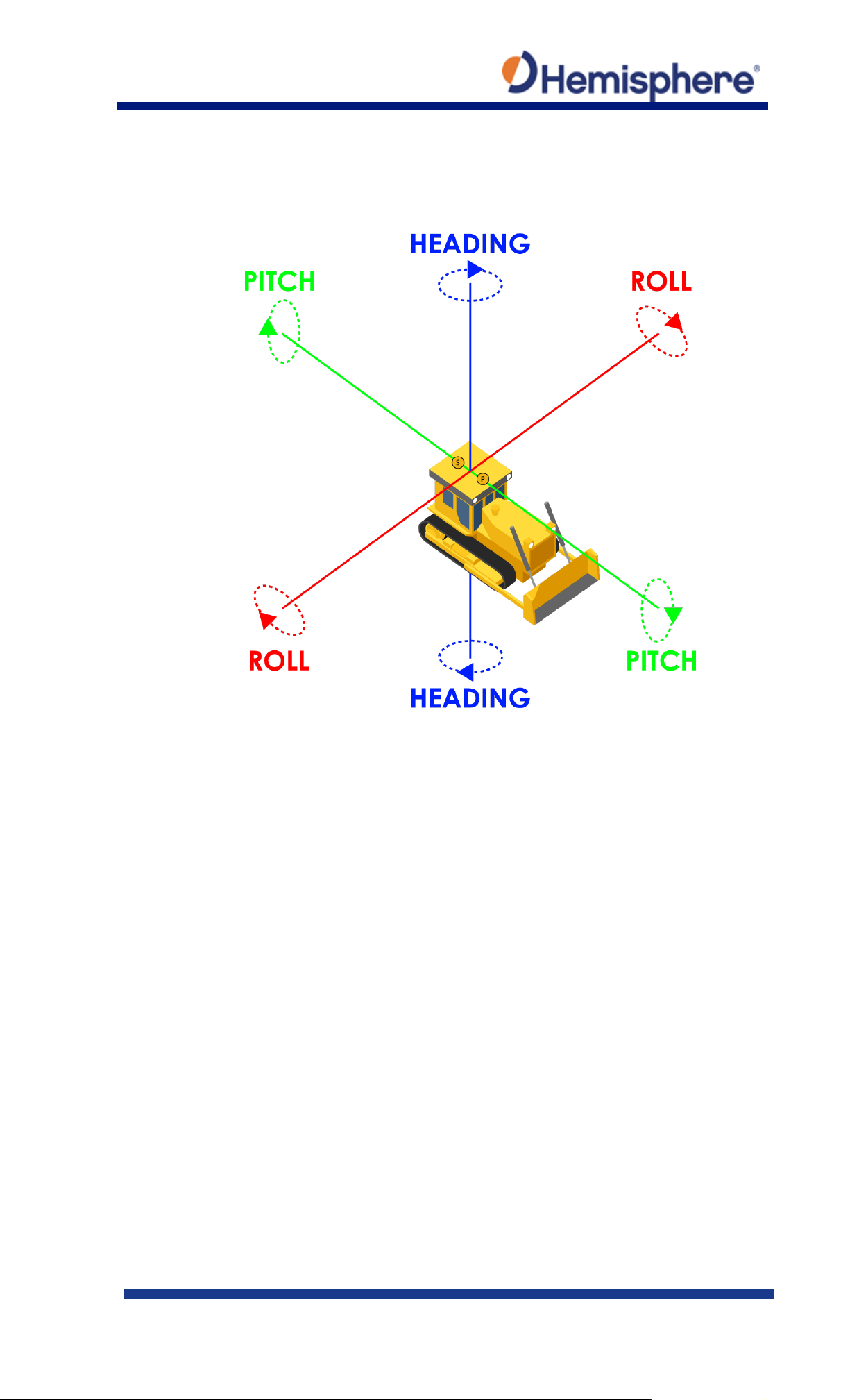
• You may need to adjust the pitch/roll output to calibrate the
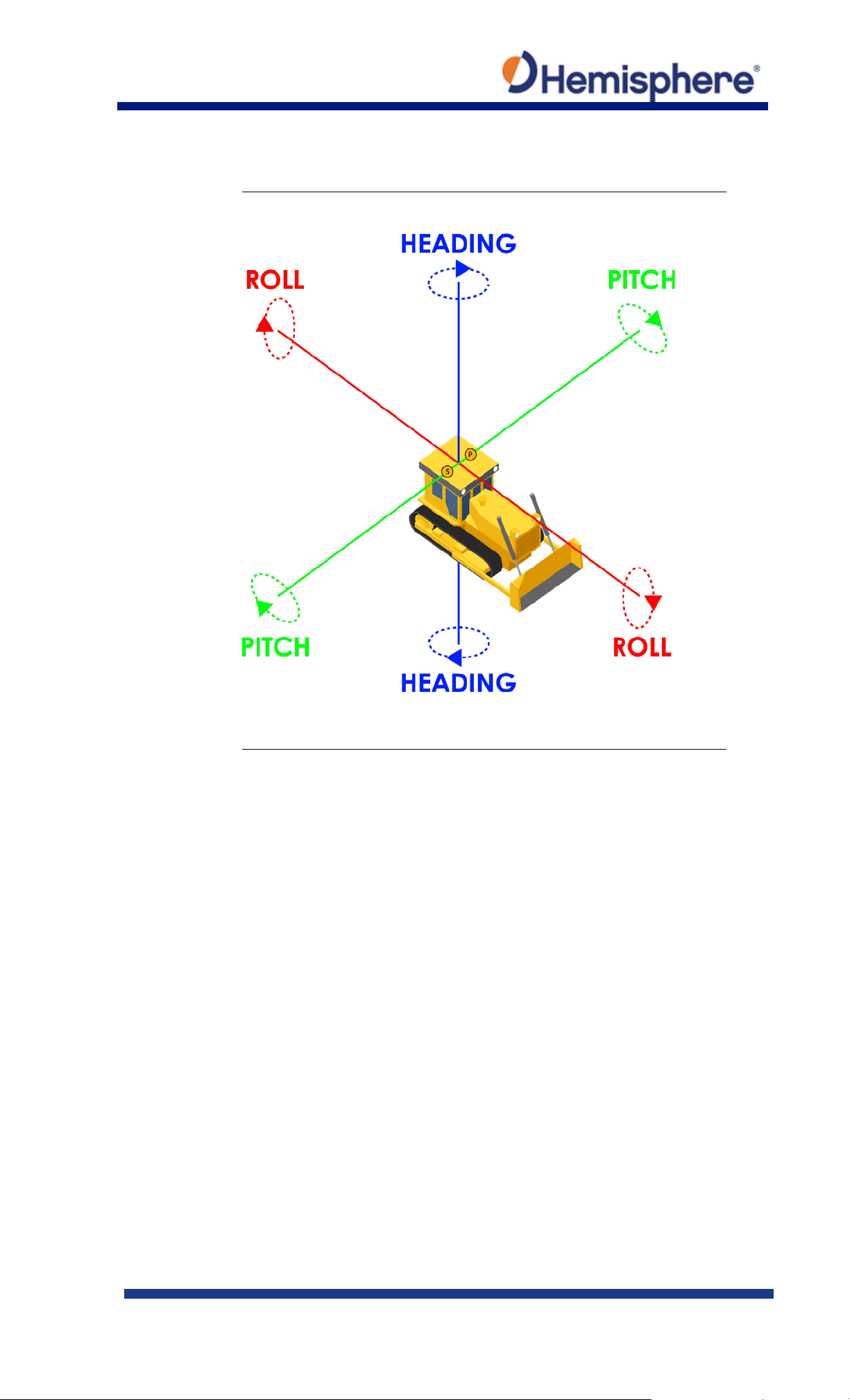
orientation
machine’s axis. In this orientation:
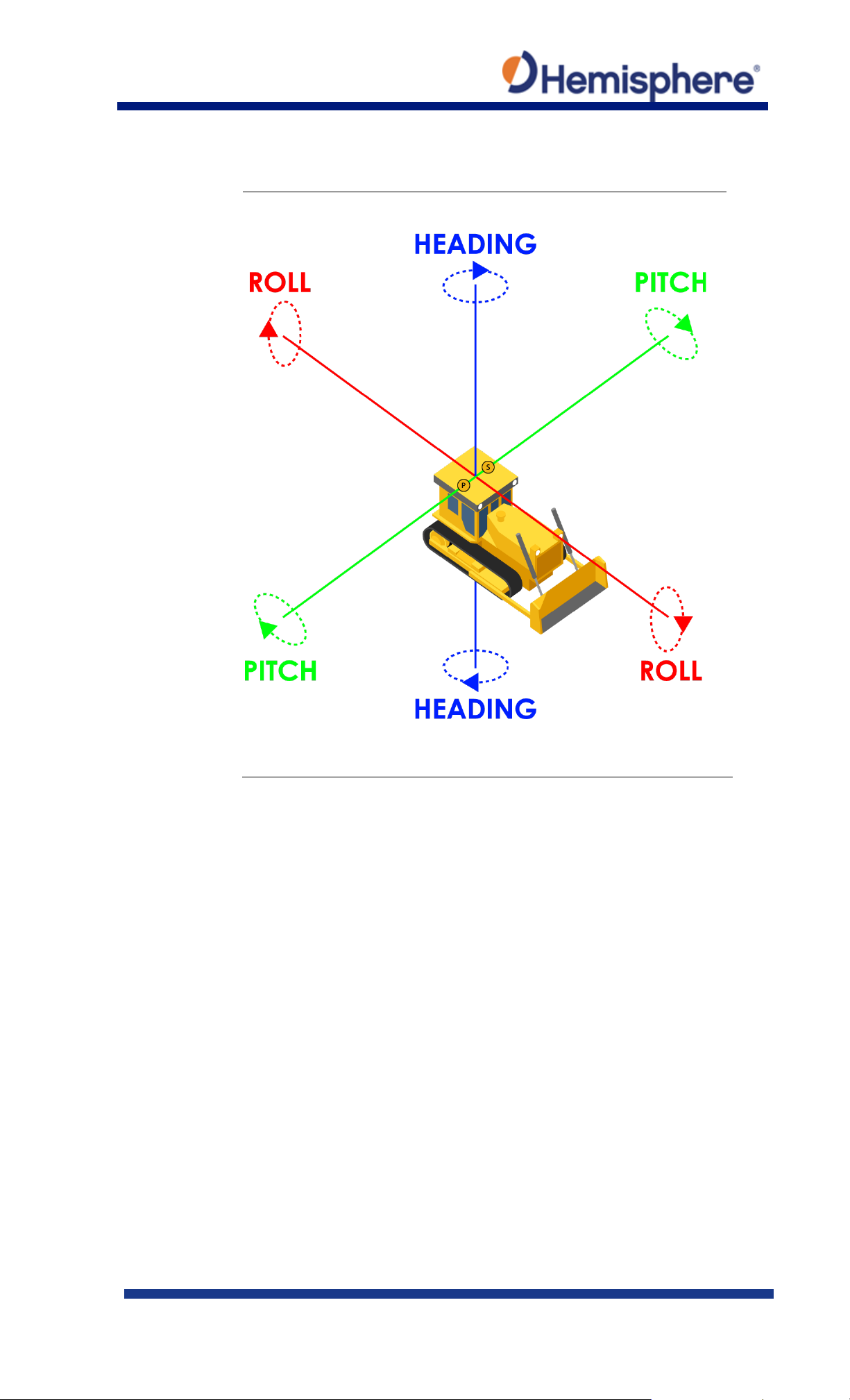
• Enter a heading bias of +90° if the secondary antenna is installed
on the right side of the machine, and -90° if the secondary
antenna is installed on the left side of the machine.
• Configure the receiver to specify the GNSS receiver is measuring
the roll axis using the VR1000 WebUI.
• Enter a roll bias to properly output the pitch and roll values.
• You may need to adjust the pitch/roll output to calibrate the
`Continued on next page
875-0422-10 Vector VR1000 QRG Rev A1
March 29, 2019 Page 2 of 36
Page 3
Mounting
Figure 2: 0-degree heading bias example
Vector VR1000 GNSS Receiver Quick Reference Guide (QRG),
Continued
orientation
Continued on next page
875-0422-10 Vector VR1000 QRG Rev A1
March 29, 2019 Page 3 of 36
Page 4
Mounting
Figure 3: 90-degree heading bias example
Vector VR1000 GNSS Receiver Quick Reference Guide (QRG),
Continued
orientation
example
Continued on next page
875-0422-10 Vector VR1000 QRG Rev A1
March 29, 2019 Page 4 of 36
Page 5
Mounting
Figure 4: Negative 90-degree heading bias example
Vector VR1000 GNSS Receiver Quick Reference Guide (QRG),
Continued
orientation
example,
continued
Continued on next page
875-0422-10 Vector VR1000 QRG Rev A1
March 29, 2019 Page 5 of 36
Page 6
Mounting
Figure 5: 180-degree heading bias example
Vector VR1000 GNSS Receiver Quick Reference Guide (QRG),
Continued
orientation
example,
continued
Continued on next page
875-0422-10 Vector VR1000 QRG Rev A1
March 29, 2019 Page 6 of 36
Page 7
Mounting
options
The VR1000 allows for two different mounting options: mount with
bolts, or mount with magnets.
Serial port
You may configure Port A or Port B of the GNSS receiver to output
devices to which they are connected. Flow control is not supported.
Baud Rates &
When selecting your baud rate and message types, use the
GNSS Technical Reference Manual.
Vector VR1000 GNSS Receiver Quick Reference Guide (QRG),
Continued
configuration
Message Types
any combination of data.
Port A can have a different configuration from Port B in data
message output, data rates, and the baud rate of the port, and
configure the ports independently based upon your needs.
Note: For successful communications, use the 8-N-1 protocol and
set the baud rate of the VR1000’s serial ports to match that of the
following formula to calculate the bits/sec for each message and
sum the results to determine the baud rate for your required data
throughput.
Message output rate * Message length (bytes) * bits in byte =
Bits/second
(1 character = 1 byte, 8 bits = 1 byte, use 10 bits/byte to account for
overhead).
For information on message output rates refer to the Hemisphere
Continued on next page
875-0422-10 Vector VR1000 QRG Rev A1
March 29, 2019 Page 7 of 36
Page 8
VR1000
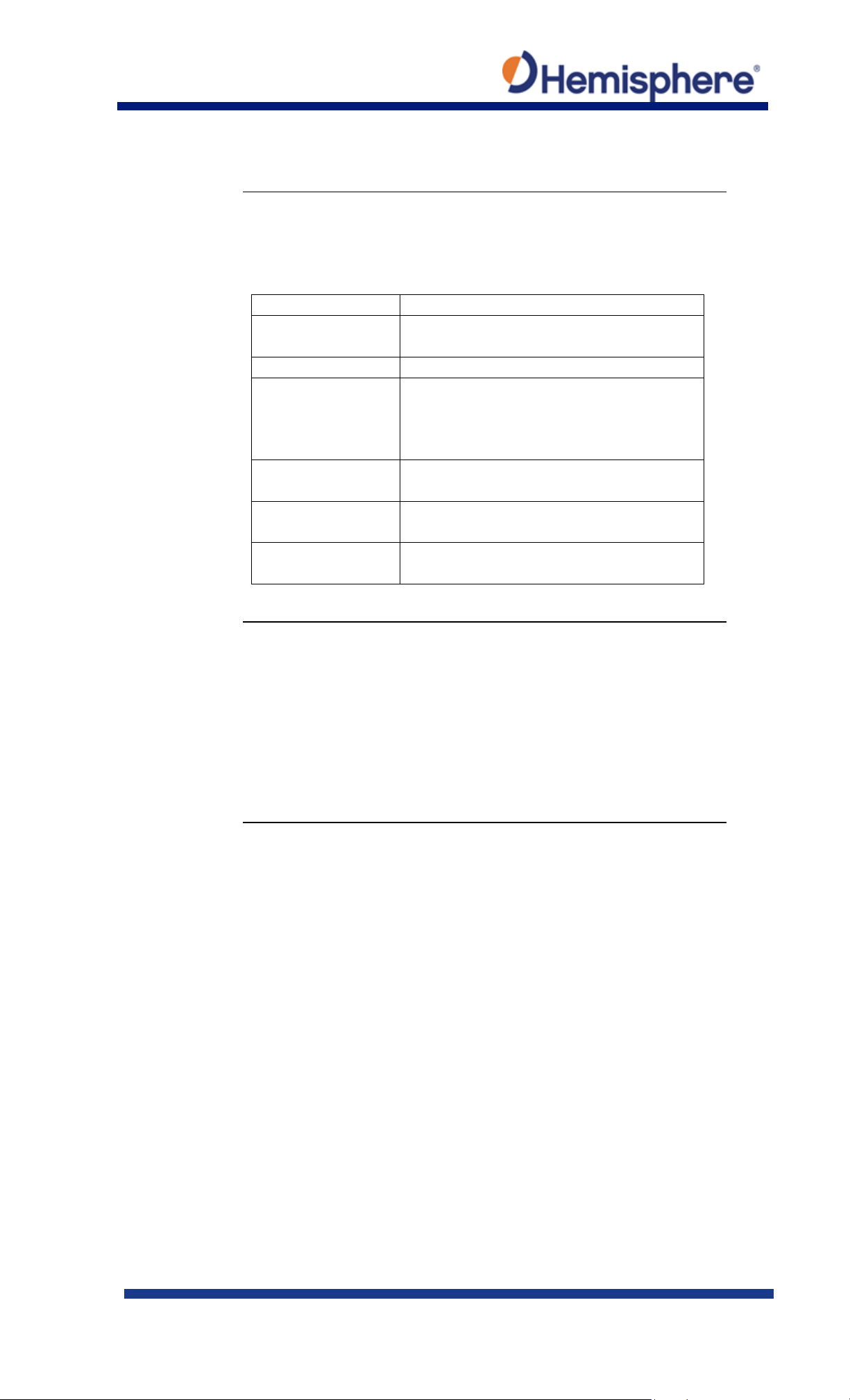
Table 1 lists the communication items and technical specifications
Item
Specification
I/O ports
2x CAN, 1x Ethernet, 2x Serial (Port A
RS232, Port B RS232/RS422)
Baud rates
4800 - 115200
Correction I/O
Atlas, Hemisphere GNSS proprietary,
binary
Timing output
1PPS, CMOS, active high, rising edge sync,
10 kΩ, 10 pF load
Event marker input
CMOS, active low, falling edge sync, 10
kΩ, 10 pF load
Radio Interfaces
Bluetooth 2.0 (Class 2), Wi-Fi 2.4 GHz, UHF
(400 MHz)
Power/data
For VR1000 pin-out information, refer to Table 2: VR1000 Pin-Out
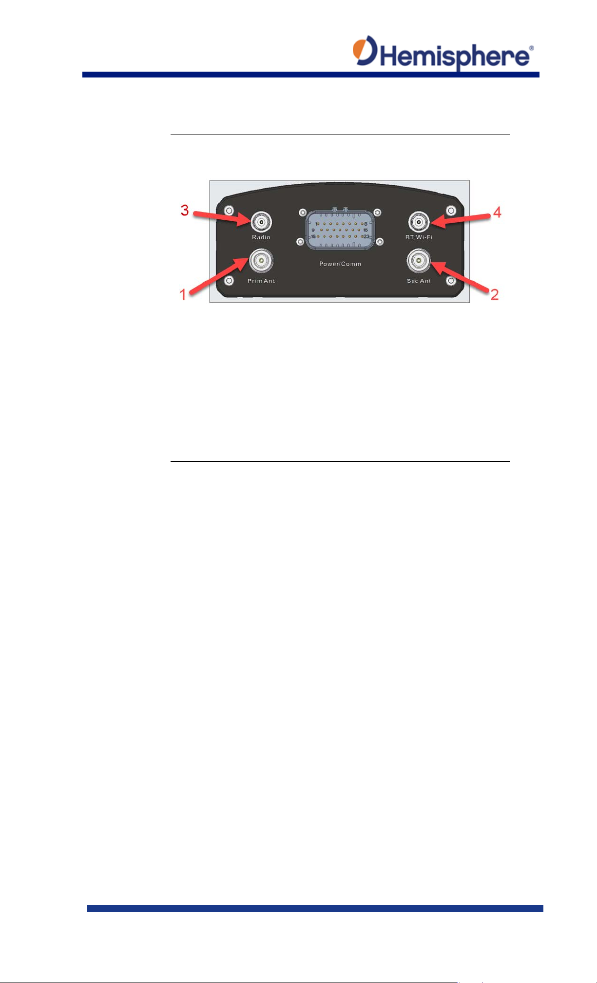
4. GNSS ANT (N-Type x 2)
Vector VR1000 GNSS Receiver Quick Reference Guide (QRG),
Continued
communication
specifications
of the VR1000 GNSS receiver.
Table 1: VR1000 Communication Specifications
protocol
RTCM v2.3 (DGPS), RTCM v3 (RTK), CMR,
CMR+ 1 NMEA 0183, Hemisphere GNSS
cable pin-out
assignments,
continued
assignments and Figure 7: VR1000 Back Panel and Pin-Out.
VR1000 Back Panel Connector Definition:
1. PWR/Comm (23PIN x 1)
2. RADIO (TNC x 1)
3. BT/Wi-Fi (TNC x 1)
Continued on next page
875-0422-10 Vector VR1000 QRG Rev A1
March 29, 2019 Page 8 of 36
Page 9
Power/data
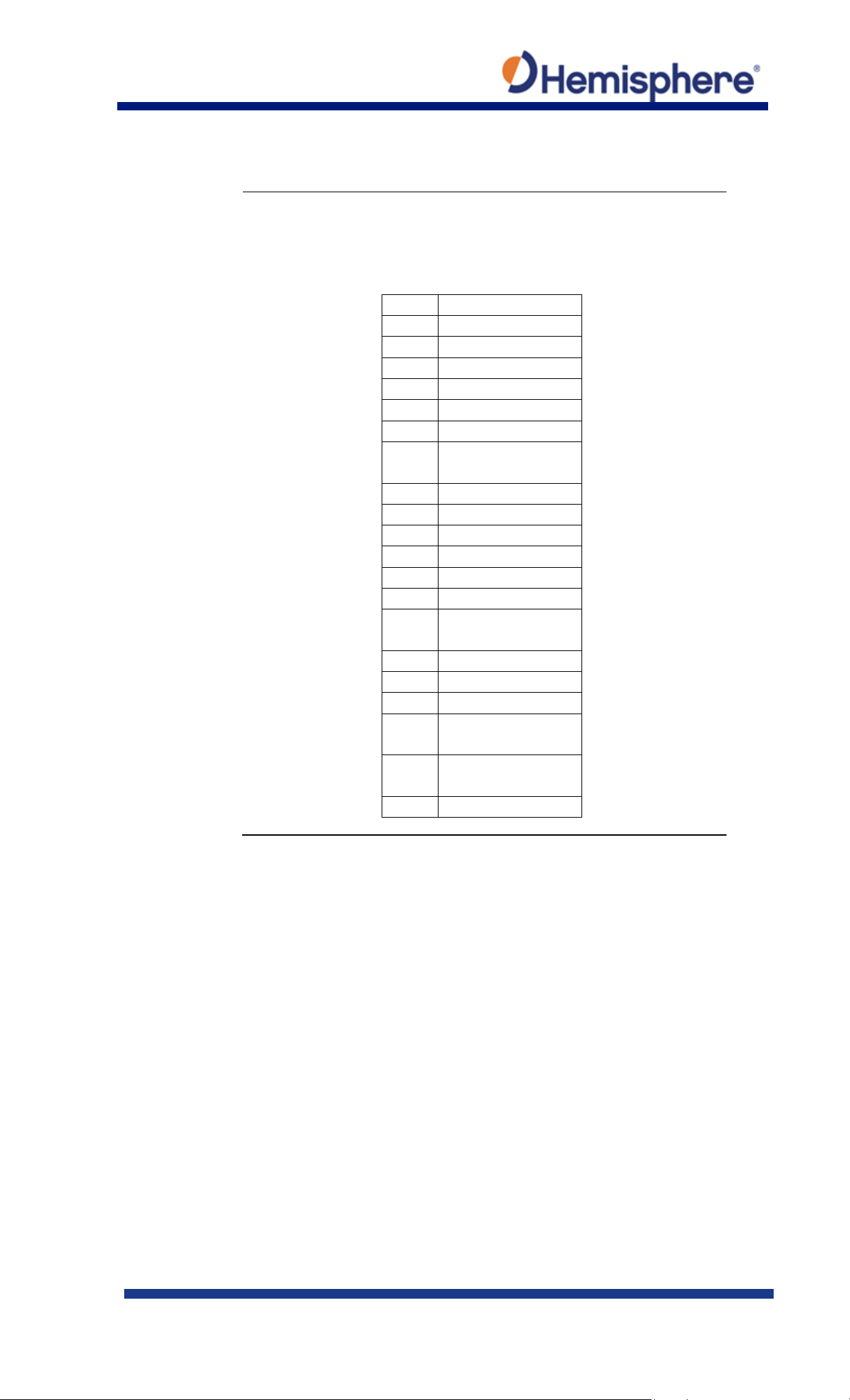
Table 2 lists the VR1000 connector pin-out. Refer to Appendix B,
Pin
Description
1
CAN2 Low
2
CAN1 High
3
Ethernet RX-
4
Ethernet TX-
5
RS232 Port A Rx
6
1PPS OUT
7
Port B RS422
TX+/SPEED OUT
8/15
Power Ground
9
CAN2 High
10
CAN1 Low
11
Ethernet RX+
12
Ethernet TX+
13
RS232 Port A Tx
14
Port B RS422 RX/EVENT MARK
16
CAN2 Shield
17
CAN1 Shield
18/19
Signal Ground
20
Port B RS232
TX/RS422 TX-
21
Port B RS232
RX/RS422 RX+
22/23
Power Positive
Vector VR1000 GNSS Receiver Quick Reference Guide (QRG),
Continued
cable pin-out
assignments,
continued
Figure B-1: Cable drawing for more detailed information.
Table 2: VR1000 Connector Pin-out
Continued on next page
875-0422-10 Vector VR1000 QRG Rev A1
March 29, 2019 Page 9 of 36
Page 10
Power/data
Figure 6 shows the VR1000 back panel and pin-out.
BT/Wi-Fi RF
Vector VR1000 GNSS Receiver Quick Reference Guide (QRG),
Continued
cable pin-out
assignments,
continued
Figure 6: VR1000 back panel and pin-out
1. Primary antenna
GNSS Primary RF +5V to power antenna
2. Secondary antenna
GNSS Secondary RF +5V to power antenna
3. Radio antenna
Radio RF
4. BT/Wi-Fi antenna
Continued on next page
875-0422-10 Vector VR1000 QRG Rev A1
March 29, 2019 Page 10 of 36
Page 11
LED Indicators
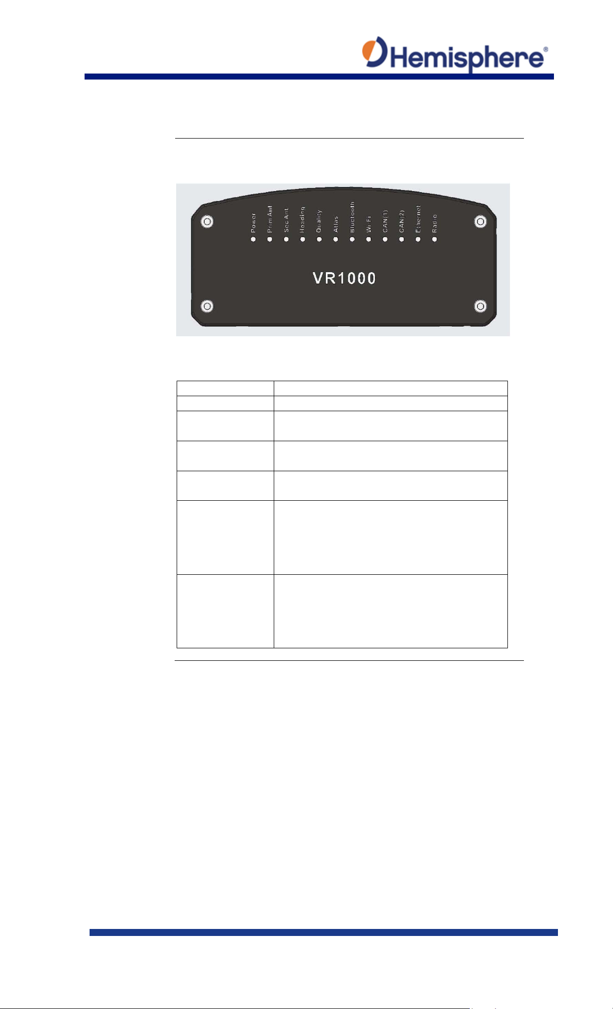
The VR1000 has twelve LED lights located on the front panel of the
Indicator
Description/Function
Power
Solid GREEN indicates receiver is powered on
Primary GNSS
Solid GREEN indicates tracking 4+ satellites
Solid RED indicates No Satellites
Secondary GNSS
Solid GREEN indicates tracking 4+ satellites
Solid RED indicates No Satellites
Heading
Solid GREEN indicates 2D GNSS heading
Solid AMBER indicates 2D sensor heading
Quality
Solid GREEN indicates RTK fixed
Solid RED indicates No Satellites
Atlas
Flashes GREEN each time an Atlas message is
locked
Vector VR1000 GNSS Receiver Quick Reference Guide (QRG),
Continued
unit. Table 3 below describes each LED indicator.
Figure 7: VR1000 LED
Table 3: LED indicators
Flashing GREEN (1/sec) indicates DGPS / Float
Solid AMBER indicates Autonomous
Flashing AMBER indicates No Position
received
Solid GREEN indicates Atlas locked
Solid AMBER indicates Atlas activated but not
Continued on next page
875-0422-10 Vector VR1000 QRG Rev A1
March 29, 2019 Page 11 of 36
Page 12
LED Indicators,
Indicator
Description/Function
Bluetooth
Solid BLUE indicates Bluetooth is turned on
connected
Wi-Fi
Solid GREEN indicates Wi-Fi is operational
connected
CAN1
Solid GREEN indicates CAN operational
Flashing GREEN (1/sec) indicates CAN in use
CAN2
Solid GREEN indicates CAN operational
Flashing GREEN (1/sec) indicates CAN in use
Ethernet
Solid GREEN indicates Ethernet operational
use
Radio
Flashes GREEN each time radio message is
data
Vector VR1000 GNSS Receiver Quick Reference Guide (QRG),
Continued
continued
Table 3: LED indicators (continued)
Flashing BLUE (1/sec) indicates Bluetooth is
Flashing GREEN (1/sec) indicates Wi-Fi is
Flashing GREEN (1/sec) indicates Ethernet in
received/sent
Solid GREEN indicates radio mode but no
Continued on next page
875-0422-10 Vector VR1000 QRG Rev A1
March 29, 2019 Page 12 of 36
Page 13
Recommend-
When interfacing to other devices, ensure the transmit data
using the WebUI.
Power/Data
The VR1000 uses a single 3 m cable for power and data input/
directly to the battery.
Vector VR1000 GNSS Receiver Quick Reference Guide (QRG),
Continued
ations for
connecting to
other devices
output and the signal grounds from the VR1000 are connected to
the data input, and signal grounds of the other device.
The RS-422 is a balanced signal with positive and negative signals
referenced to ground; ensure you maintain the correct polarity.
When connecting the transmit data output positive signal to the
receive line of the other device, it should be connected to the
receive positive terminal.
The negative transmit data signal from the VR1000 is then
connected to the receive data negative input of the other device.
For a list of Hemisphere GNSS commands, please refer to the
Hemisphere GNSS Technical Reference Manual. To configure the
unit through the WebUI, please refer to Configuring the VR1000
cable
considerations
output.
The receiver end of the cable is terminated with an
environmentally-sealed 23-Pin connection while the opposite end
is terminated with multiple connectors. Ensure that the PWR-/Bwire is connected to a clean chassis ground. DO NOT ground
875-0422-10 Vector VR1000 QRG Rev A1
March 29, 2019 Page 13 of 36
Page 14
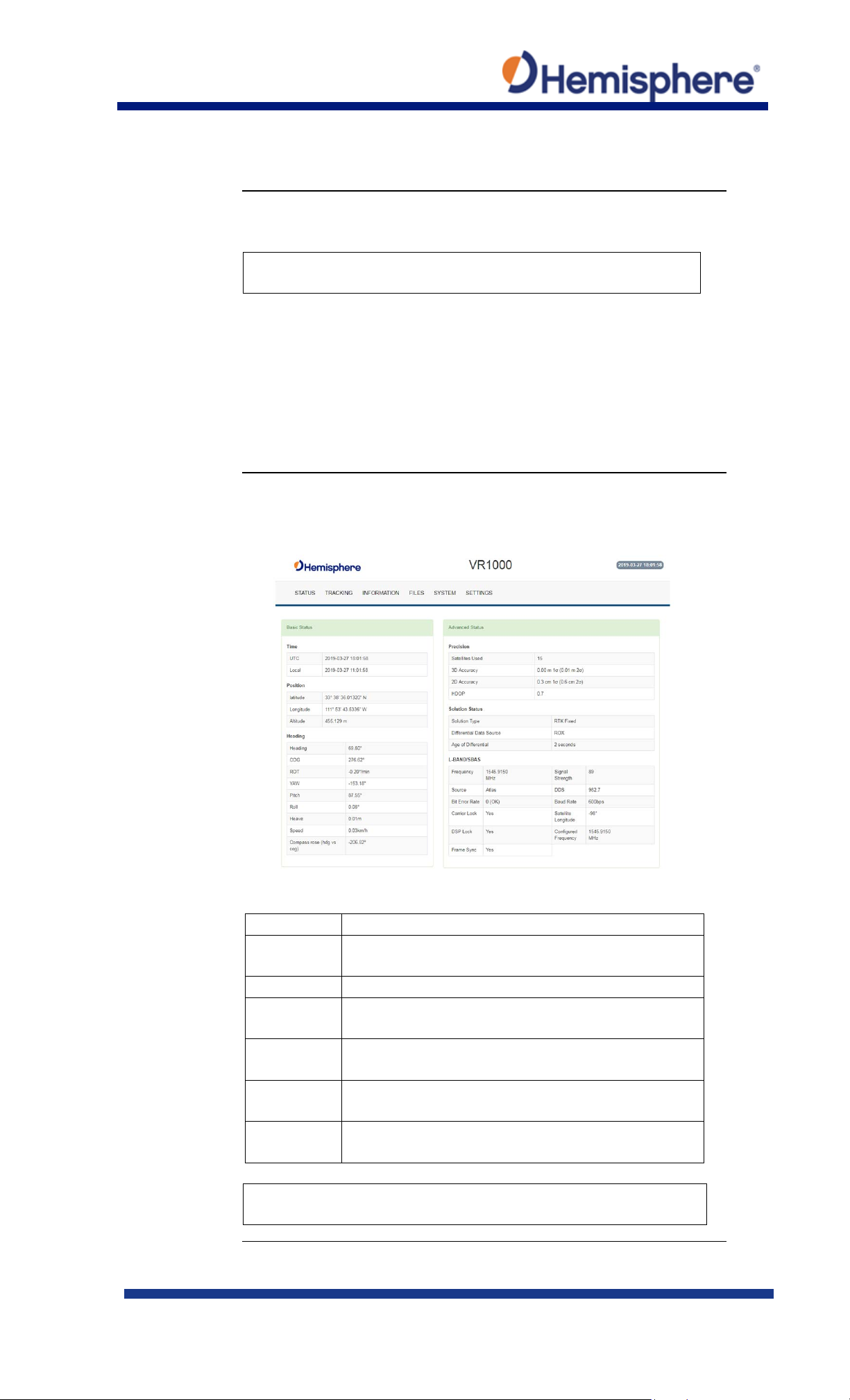
Overview
The VR1000 is equipped with an onboard WebUI.
192.168.100.1
Status
The VR1000 Status tab displays. You can view RX Info, Position,
Field
Description
Time
UTC time obtained from satellites, Local time
configured in Settings; Miscellaneous tab
Position
Latitude, Longitude, Altitude
Heading
Heading, COG, ROT, YAW, pitch, roll, heave, speed,
and the difference between heading and COG
Precision
Satellites used in solution, 3D Accuracy, 2D
Accuracy, horizontal dilution of precision
Solution
Status
Solution type, correction source, correction signal
latency
L-band
/SBAS
Atlas Frequency, Source, Bit Error Rate, Carrier
Lock, DSP Lock, Frame Sync, Frame Sync 2*
A, Terms and Definitions.
Configuring the VR1000 Using the WebUI
Note: The VR1000 WebUI supports Chrome and Firefox web
browsers.
First, connect the Bluetooth/WiFi antenna to the connector. The
receiver displays as an available Wi-Fi device in your available
networks. Connect your device to the VR1000’s Wi-Fi. The
password is hgnss1234.
Open a web browser window and type the following IP address:
Heading, L-band and SBAS.
Table 4: Status fields
*Note: For a definition of the L-band/SBAS fields refer to Appendix
875-0422-10 Vector VR1000 QRG Rev A1
March 29, 2019 Page 14 of 36
Continued on next page
Page 15
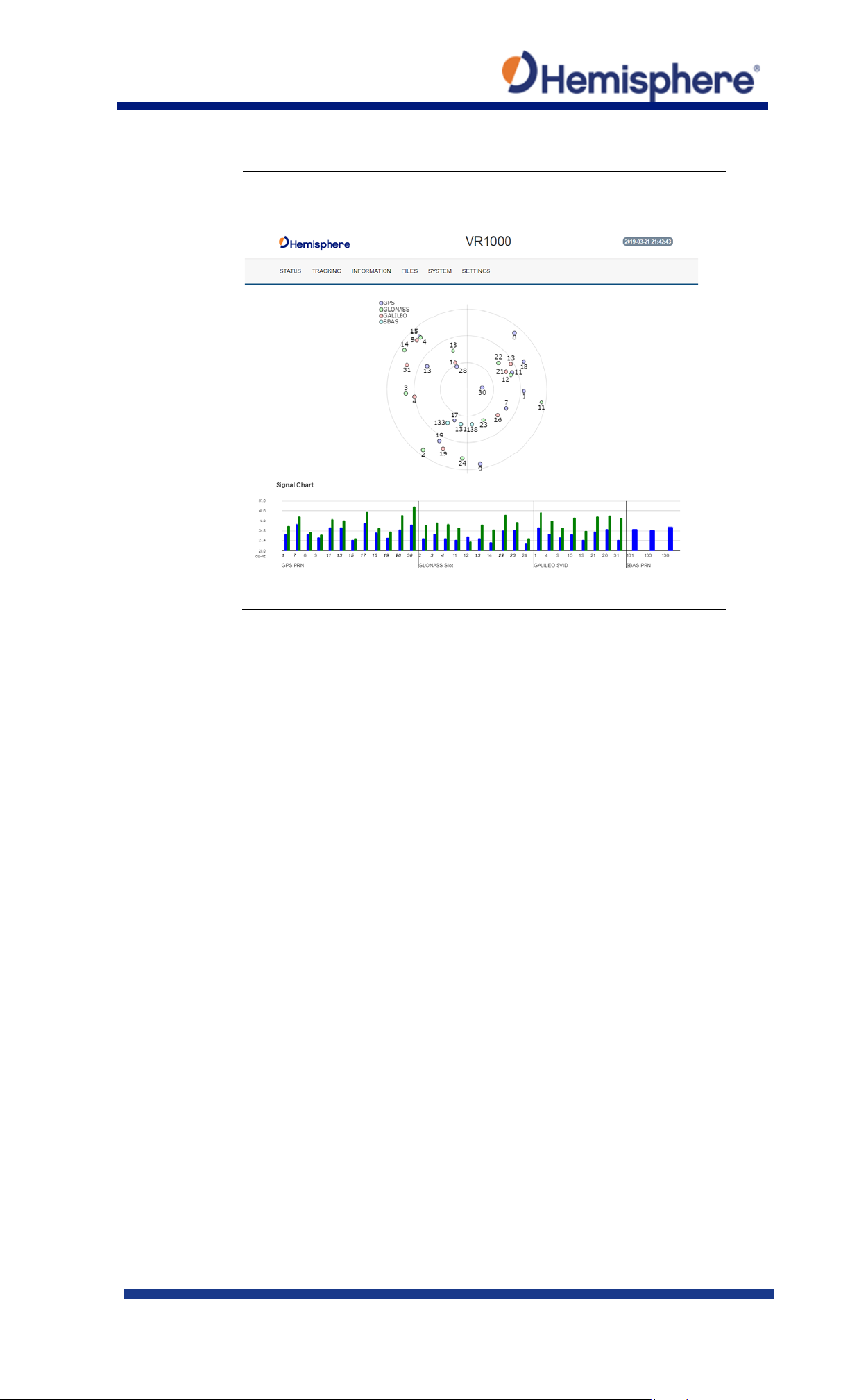
Tracking
On the Tracking tab, the Sky Plot shows the azimuth, elevation,
Configuring the VR1000 Using the WebUI, Continued
and SNR values of all tracked satellites.
Continued on next page
875-0422-10 Vector VR1000 QRG Rev A1
March 29, 2019 Page 15 of 36
Page 16
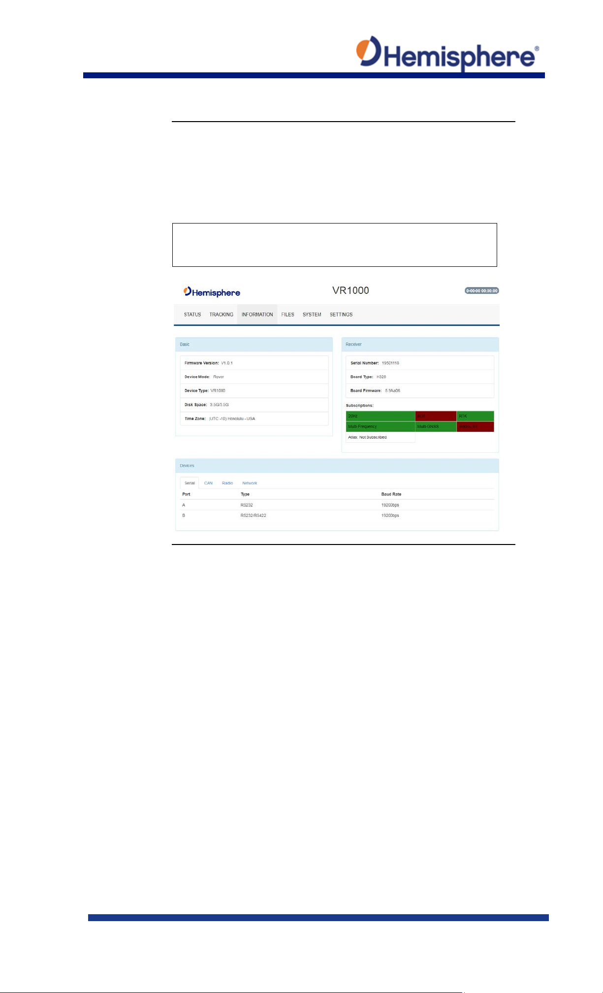
Information tab
On the Information tab, the Serial Number, Board Type, Board
Configuring the VR1000 Using the WebUI, Continued
Firmware, Subscriptions, Devices, RX info, and Port information is
displayed.
Activated items are in green.
Important: If you have purchased an activation or subscription,
use the field on the System screen to enter the Subscription Code,
and click the ‘arrows’ button.
Continued on next page
875-0422-10 Vector VR1000 QRG Rev A1
March 29, 2019 Page 16 of 36
Page 17
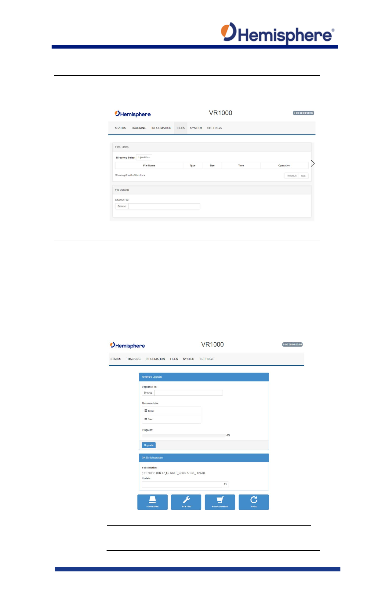
Files tab
Use the file tab to upload files and download log files from the
System
The System tab can be used to upgrade both GNSS firmware or
Bluetooth is enabled, an option will be given to disable Bluetooth.
Configuring the VR1000 Using the WebUI, Continued
receiver.
carrier board firmware. You can add subscription codes on this
screen.
Use the buttons at the bottom of the screen:
• Format Disk-format the internal storage
• Self Test- run a receiver self-test
• Factory Restore- restore the unit to factory settings
• Reboot-reboot the unit
Note: The filesystem cannot be used when Bluetooth is enabled. If
875-0422-10 Vector VR1000 QRG Rev A1
March 29, 2019 Page 17 of 36
Continued on next page
Page 18
System,
After Bluetooth is disabled, the filesystem displays. Any log files
board firmware, and press “Upload.”
Settings
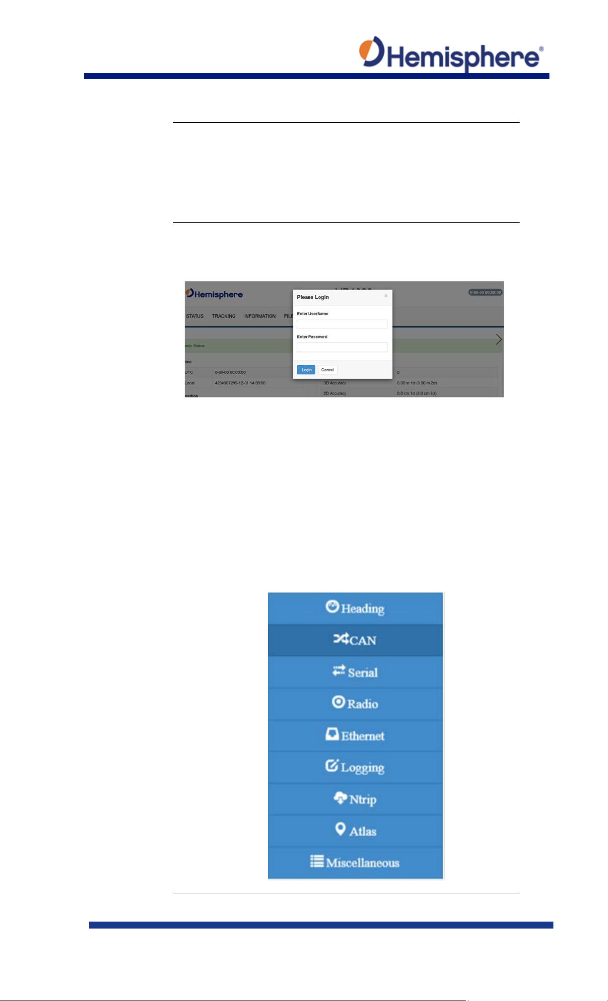
A pop-up dialog box displays prompting for username and password.
Configuring the VR1000 Using the WebUI, Continued
continued
stored on the receiver will be available for download.
To upgrade firmware, click Choose File, select the GNSS or carrier
Type the UserName: admin and the password: Hemi3384.
You can configure the following using the VR1000 WebUI:
• Heading
• CAN
• Serial
• Radio
• Ethernet
• Logging
• Ntrip
• Atlas
• Miscellaneous
875-0422-10 Vector VR1000 QRG Rev A1
March 29, 2019 Page 18 of 36
Continued on next page
Page 19
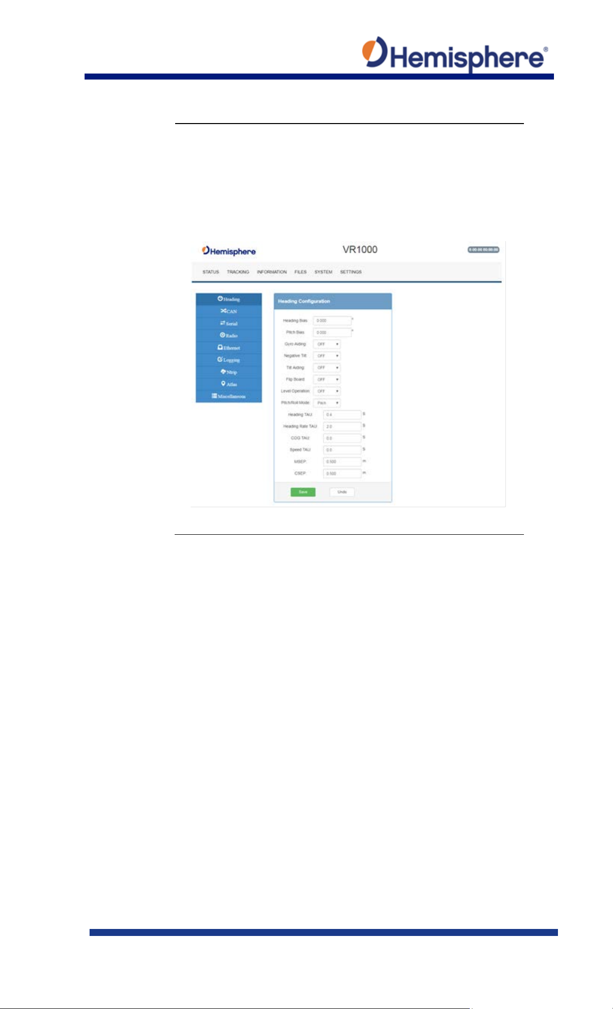
Heading menu
The Heading menu displays the following data.
Configuring the VR1000 Using the WebUI, Continued
Various heading settings can also be configured.
Click the box of the desired setting and type the configuration
setting values.
Continued on next page
875-0422-10 Vector VR1000 QRG Rev A1
March 29, 2019 Page 19 of 36
Page 20
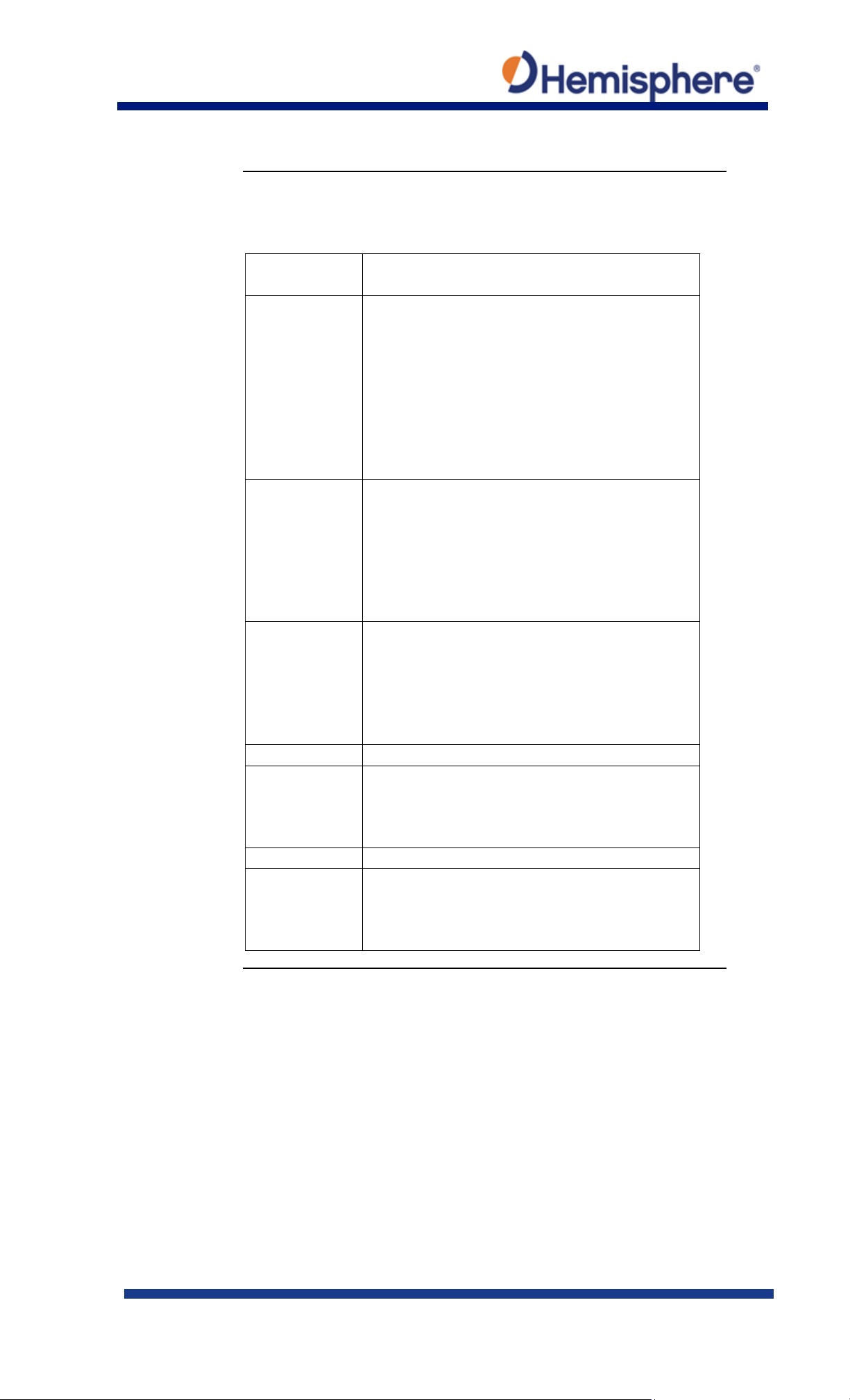
Heading menu,
Table 5 lists the heading configurations.
Heading
Configuration
Description
Heading Bias
Add a bias to the heading value the receiver
Range: -180 – +180
Pitch Bias
Add a bias to the pitch value the receiver
Range: -15 – +15
Gyro Aiding
Gyro aiding enables the use of the internal gyro
obstruction in GNSS signal.
Negative Tilt
Change the sign of the pitch/roll measurement.
Tilt Aiding
Turn OFF or ON tilt aiding. When on, the
reacquisition times.
Flip Board
N/A
Level
If the Vector will be operated within +/- 10
acquisition times of the heading solution.
Configuring the VR1000 Using the WebUI, Continued
continued
Table 5: Heading Configurations
outputs.
Heading is defined as the direction of the
vector created from the primary to secondary
antenna. Heading is measured using true
north.
outputs.
If the receiver is in “roll” mode, this will add a
bias to the roll instead.
Operation
sensor and allows for the continuous output of
heading for up to three minutes during a GNSS
outage. Gyro aiding improves the reacquisition
time when GNSS heading is lost because of an
sensors are used to reduce the RTK search
volume – improving heading startup and
degrees of level, you may use this mode of
operation for increased robustness and faster
Continued on next page
875-0422-10 Vector VR1000 QRG Rev A1
March 29, 2019 Page 20 of 36
Page 21
Heading menu,
Table 5: Heading Configurations (continued)
Heading
Configuration
Description
Pitch/Roll Mode
If the antennas are mounted such that they
PITCH.
Heading TAU
Adjust the responsiveness to true heading.
turn (°/s) with gyro OFF
Heading Rate TAU
Adjust the responsiveness to the rate of
of turn (°/s2)
Configuring the VR1000 Using the WebUI, Continued
continued
model pitch, set to PITCH.
If the antennas are mounted such that they
model roll, set to ROLL.
Note: If your HBIAS is -90 or +90, set this to
ROLL. If your HBIAS is 0 or 180, set this to
If the machine is large and unable to turn
quickly, increase this value.
For longer baselines (10 m) HTAU should be
between 0.1 and 0.5, since the gyro
introduces noise.
Default value: 0.1 s with gyro enabled
Range: 0.0 to 60 s
Formula: htau (s) = 40 / max rate of turn
(°/s) with gyro ON htau (s) = 10 / max rate of
heading change.
If the machine is large and unable to turn
quickly, increase this value.
Default value: 2.0 s with gyro enabled
Range: 0.0 to 60 s
Formula: hrtau (s) = 10 / max rate of the rate
Continued on next page
875-0422-10 Vector VR1000 QRG Rev A1
March 29, 2019 Page 21 of 36
Page 22

Heading menu,
Table 5: Heading Configurations (continued)
Heading
Configuration
Description
COG TAU
The direction the machine is moving.
of course (°/sec)
Speed TAU
Speed of machine in km/h.
(m/s2)
MSEP
The measured distance between the primary
within 2 cm.
Configuring the VR1000 Using the WebUI, Continued
continued
Adjust the responsiveness to the course over
ground measurement.
If the machine is small and dynamic, leave
this value at 0.0 s to be conservative.
If the machine is large and resistant to
motion, increase this value.
Default value: 0.0 s .
Range: 0.0 to 60 s
Formula: cogtau (s) = 10 / max rate of change
Adjust the responsiveness to speed.
If the machine is small and dynamic, leave
this value at 0.0 s to be conservative.
If the machine is large and resistant to
motion, increase this value.
Default value: 0.0 s
Range: 0.0 to 60 s
Formula: spdtau (s) = 10 / max acceleration
875-0422-10 Vector VR1000 QRG Rev A1
March 29, 2019 Page 22 of 36
and secondary antenna. Must be accurate to
Continued on next page
Page 23
Heading menu,
Table 5: Heading Configurations (continued)
Heading
Configuration
Description
CSEP
This is the antenna separation calculated by
you will not receive a valid heading.
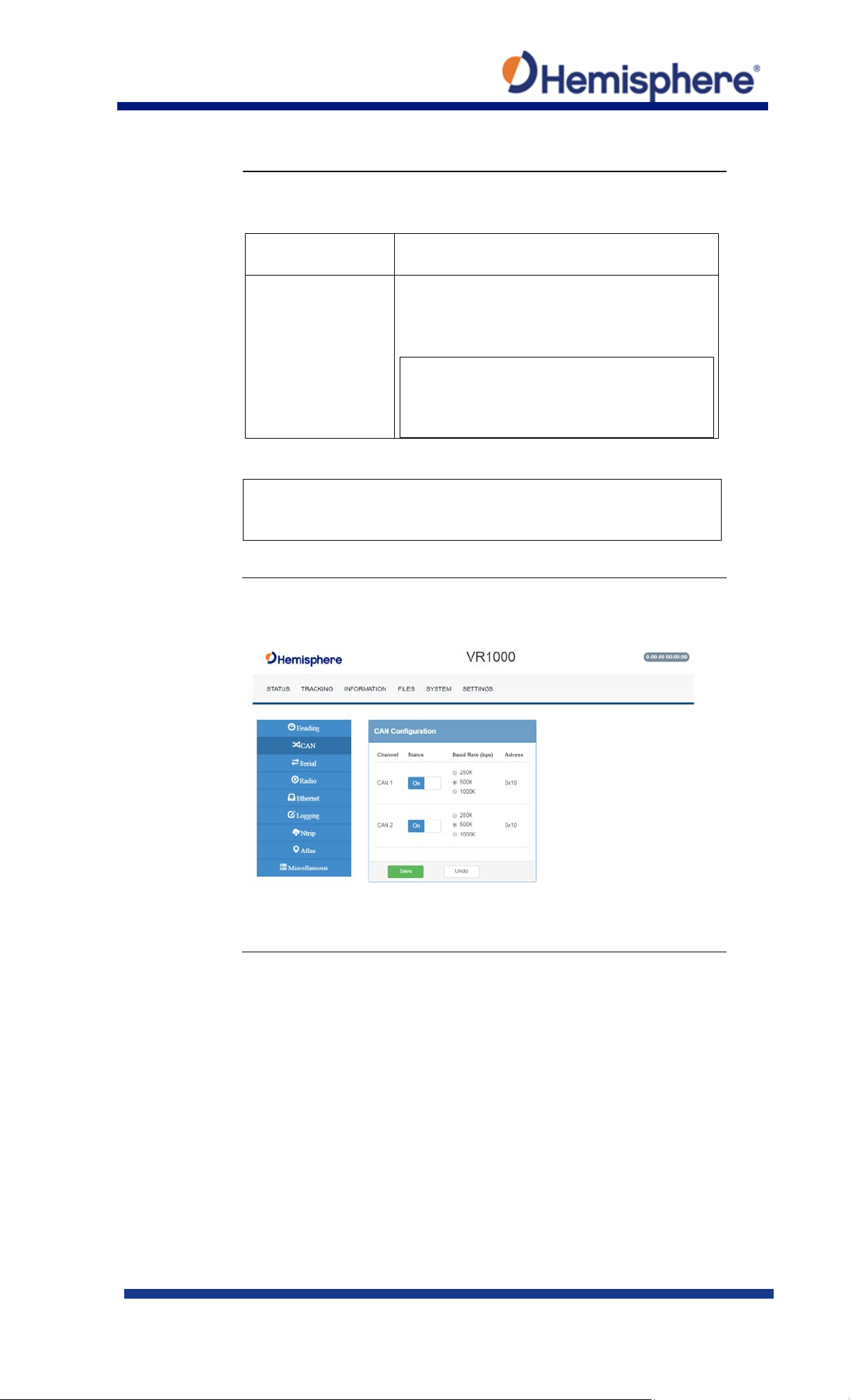
CAN
On the CAN configuration menu, turn ON/OFF CAN and select the
Configuring the VR1000 Using the WebUI, Continued
continued
the receiver. Ensure the CSEP value is within
0.02 of the MSEP value.
Note: If CSEP value is “0” the receiver is
unable to calculate the separation between
the primary and secondary antennas, and
Note: Default settings can be changed to set the time constants to
smooth heading, Course-over-Ground (COG), and speed
measurements.
Configuration
baud rate (250 kbps, 500 kbps, or 1000 kbps).
Continued on next page
875-0422-10 Vector VR1000 QRG Rev A1
March 29, 2019 Page 23 of 36
Page 24
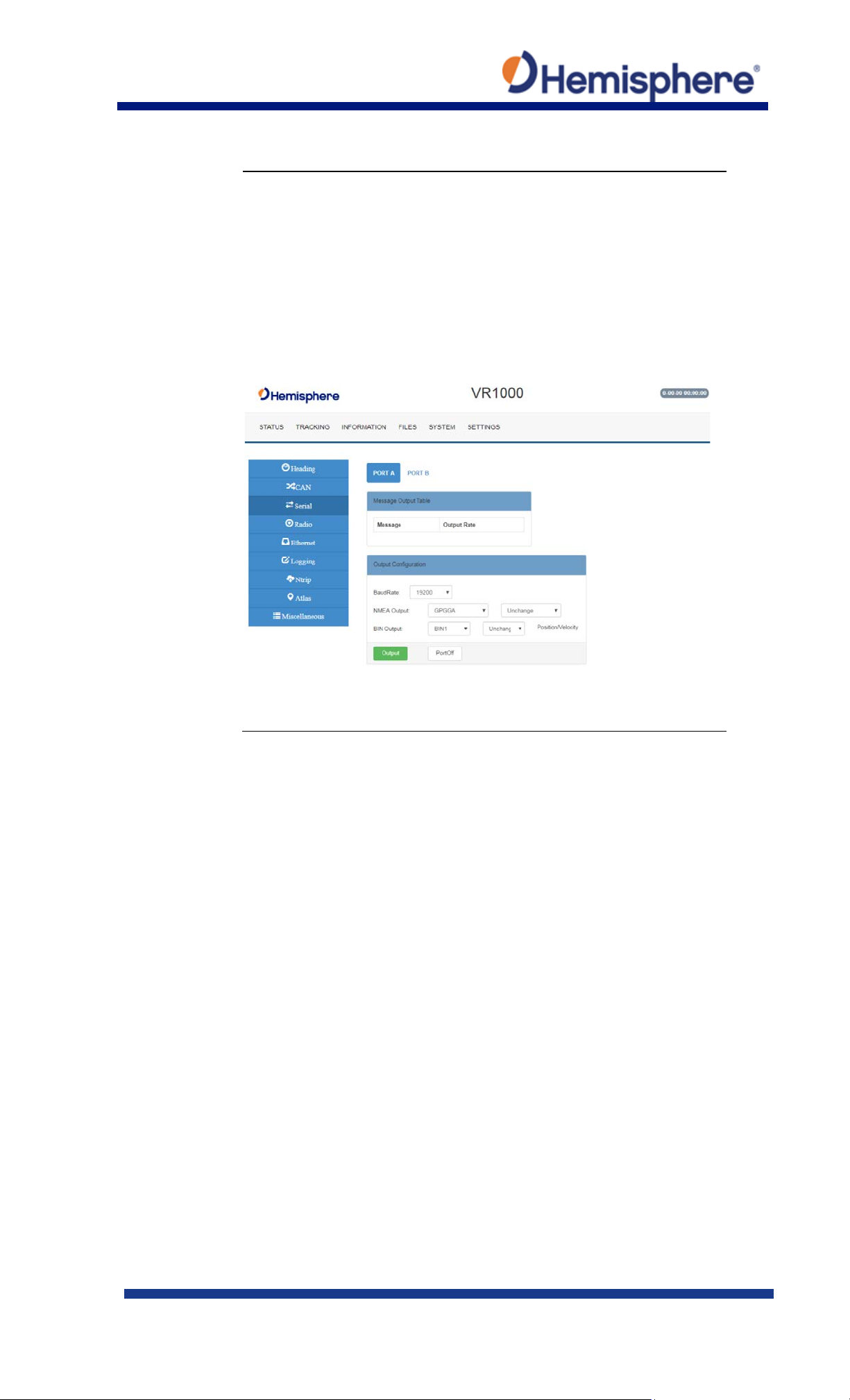
Serial
Use Serial to configure the baud rate of each serial port (PortA and
Configuring the VR1000 Using the WebUI, Continued
PortB and turn off/on specific NMEA 0183 messages and
proprietary Hemisphere BIN messages.
You can also change Port B from RS232 to RS422 and RS422 to
RS232 reciprocally.
Configure the Serial Port and click Output.
Continued on next page
875-0422-10 Vector VR1000 QRG Rev A1
March 29, 2019 Page 24 of 36
Page 25
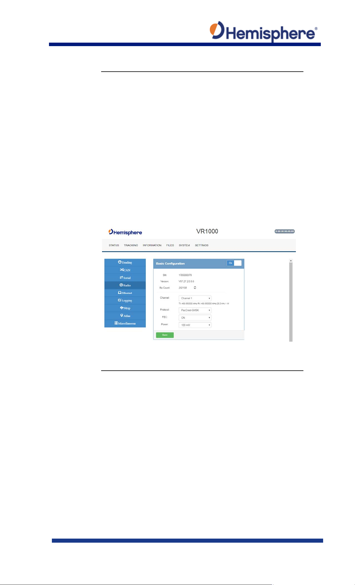
Radio Basic
Use Radio Basic to configure the internal UHF radio (protocol,
Configuring the VR1000 Using the WebUI, Continued
frequency, etc.).
The Radio Configuration defaults to a no-frequency setting.
Use the drop-down arrows to select pre-configured channels. Each
channel has an associated frequency, and bandwidth.
Select a protocol (see Table 6: Radio mode). The list of available
protocols is dependent upon the bandwidth of your channel. For
example, if the bandwidth of the channel you are using is 12.5KHz,
Trimtalk 2 will not display.
To add new channels, obtain and load a .ucf file from your dealer
using the Upload Config File button. Choose a channel and select
the protocol. For Satel protocol, you may turn FEC OFF/ON.
Continued on next page
875-0422-10 Vector VR1000 QRG Rev A1
March 29, 2019 Page 25 of 36
Page 26
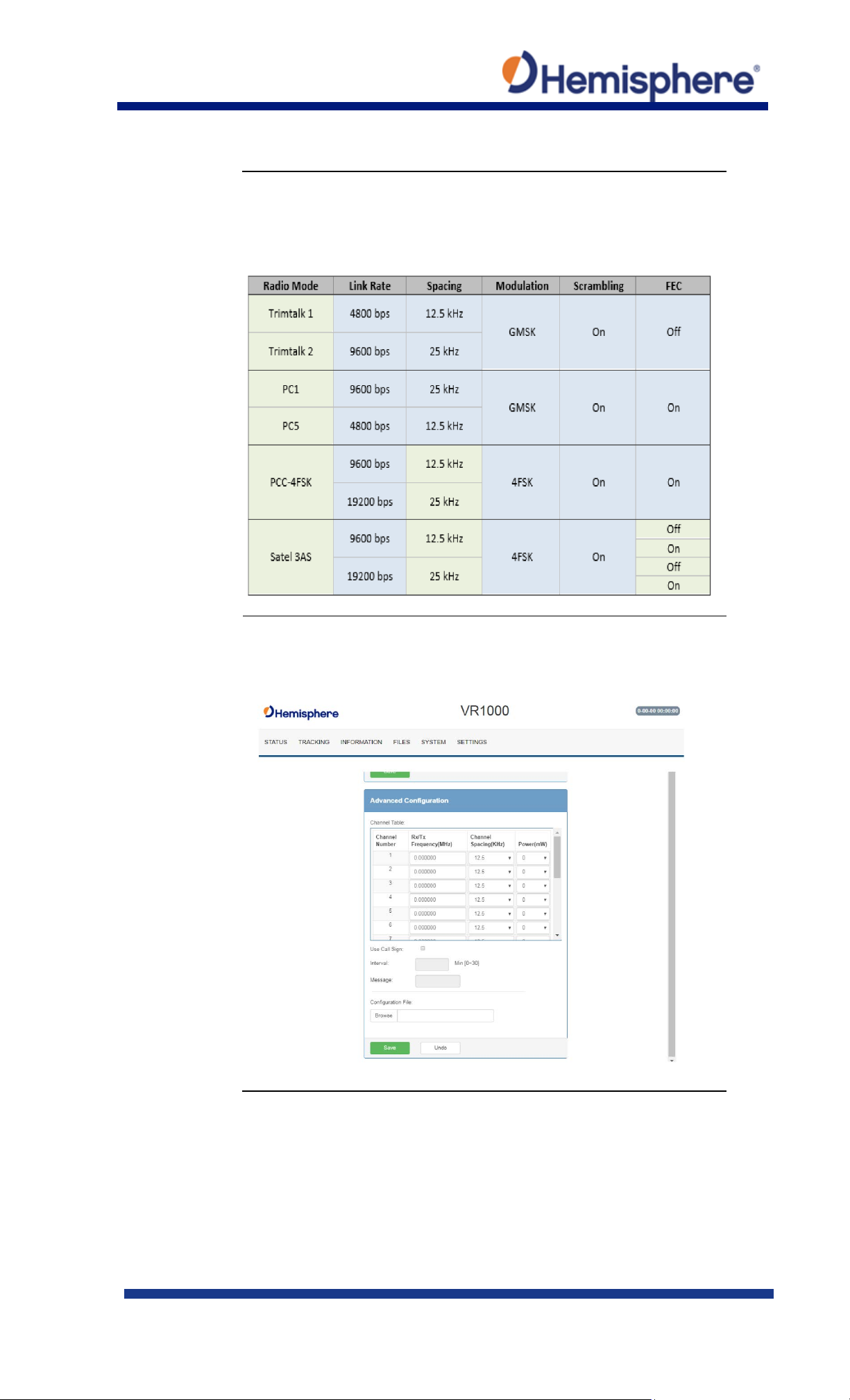
Radio Basic,
Use the following table to configure Radio settings. You may
Radio Advanced
Use the Radio Advanced Configuration screen to manually enter
Configuring the VR1000 Using the WebUI, Continued
continued
configure any settings in the blue boxes.
Table 6: Radio mode
Radio frequencies or upload a Configuration file of frequencies.
Contact HGNSS Technical Support for Configuration files.
Continued on next page
875-0422-10 Vector VR1000 QRG Rev A1
March 29, 2019 Page 26 of 36
Page 27
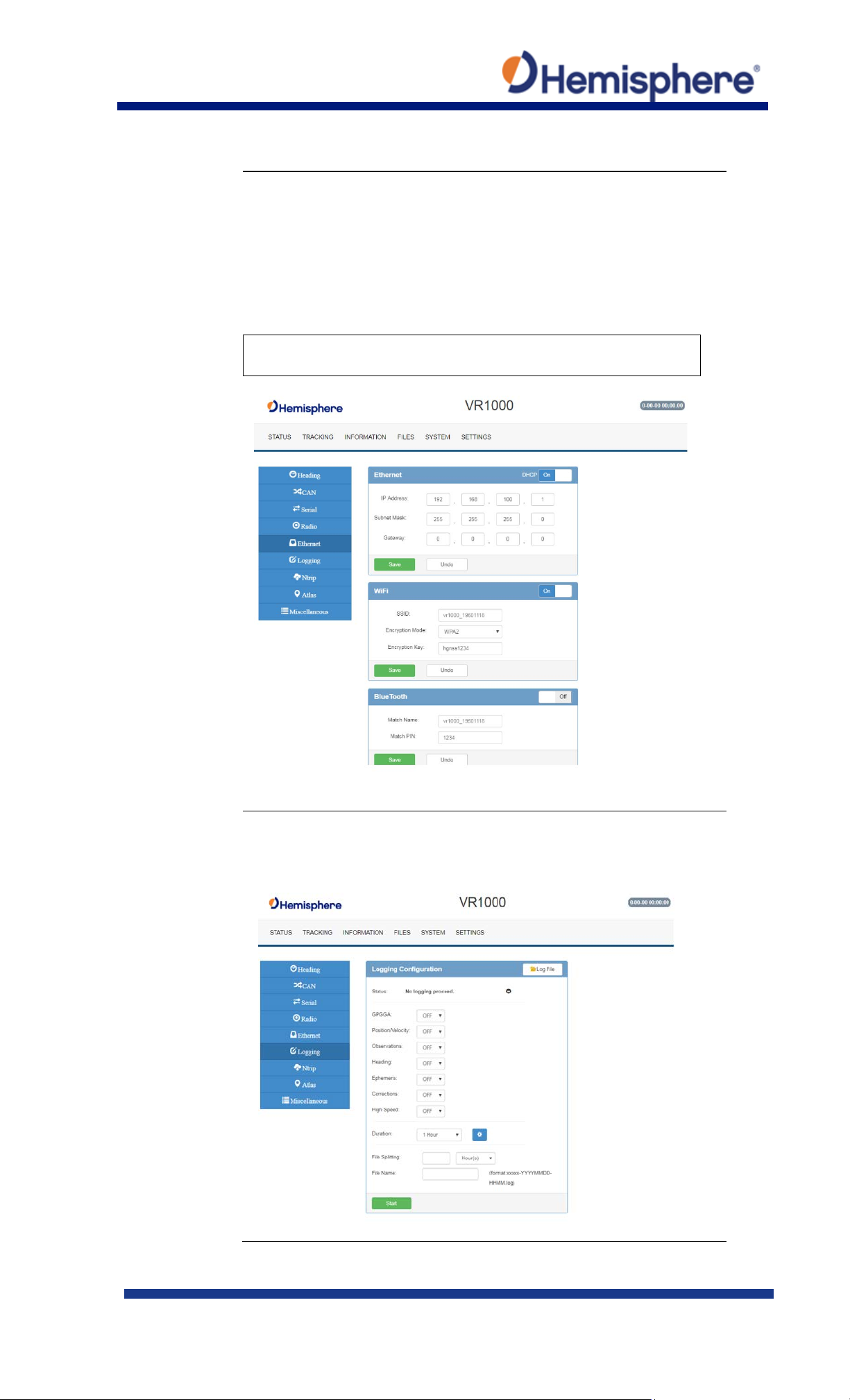
Ethernet
Use the VR1000 WebUI to configure the Ethernet connection.
Logging
Log data to the internal memory of the VR1000 or download a
Configuring the VR1000 Using the WebUI, Continued
Wi-Fi Bluetooth configuration-configure the WiFi access name,
encryption mode, and encryption key of the VR1000 in the
WiFi/Bluetooth configuration settings. Click to enable Bluetooth
options and type the PIN of the VR1000.
Note: Files cannot be downloaded from the VR1000 filesystem
when Bluetooth is enabled.
previously saved log.
Continued on next page
875-0422-10 Vector VR1000 QRG Rev A1
March 29, 2019 Page 27 of 36
Page 28
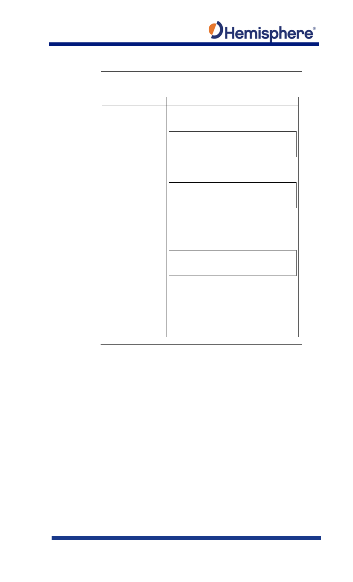
Logging,
Table 7: Logging configuration
Field
Description
GPGGA
Turn on GGA message logging at 0.2Hz, 1Hz,
or 20Hz included).
Position/Velocity
Log the position and velocity of the receiver
or 20Hz included).
Observations*
Log raw GNSS observations at 0.2Hz, 1Hz,
Heading
Heading logs the following messages:
• BIN3
Configuring the VR1000 Using the WebUI, Continued
continued
*This feature is only
available if you have a
“Raw” activation on the
receiver.
10Hz, or 20HZ.
Note: 10Hz and 20Hz are only available with
activations (some kits may come with 10Hz
at 0.2Hz, 1Hz, 10Hz, or 20HZ.
Note: 10Hz and 20Hz are only available with
activations (some kits may come with 10Hz
10Hz, or 20HZ.
Note: 10Hz and 20Hz are only available with
activations (some kits may come with 10Hz
or 20Hz included).
• GPHDT
• GPHDM
• GPHDG
• HPR
Continued on next page
875-0422-10 Vector VR1000 QRG Rev A1
March 29, 2019 Page 28 of 36
Page 29
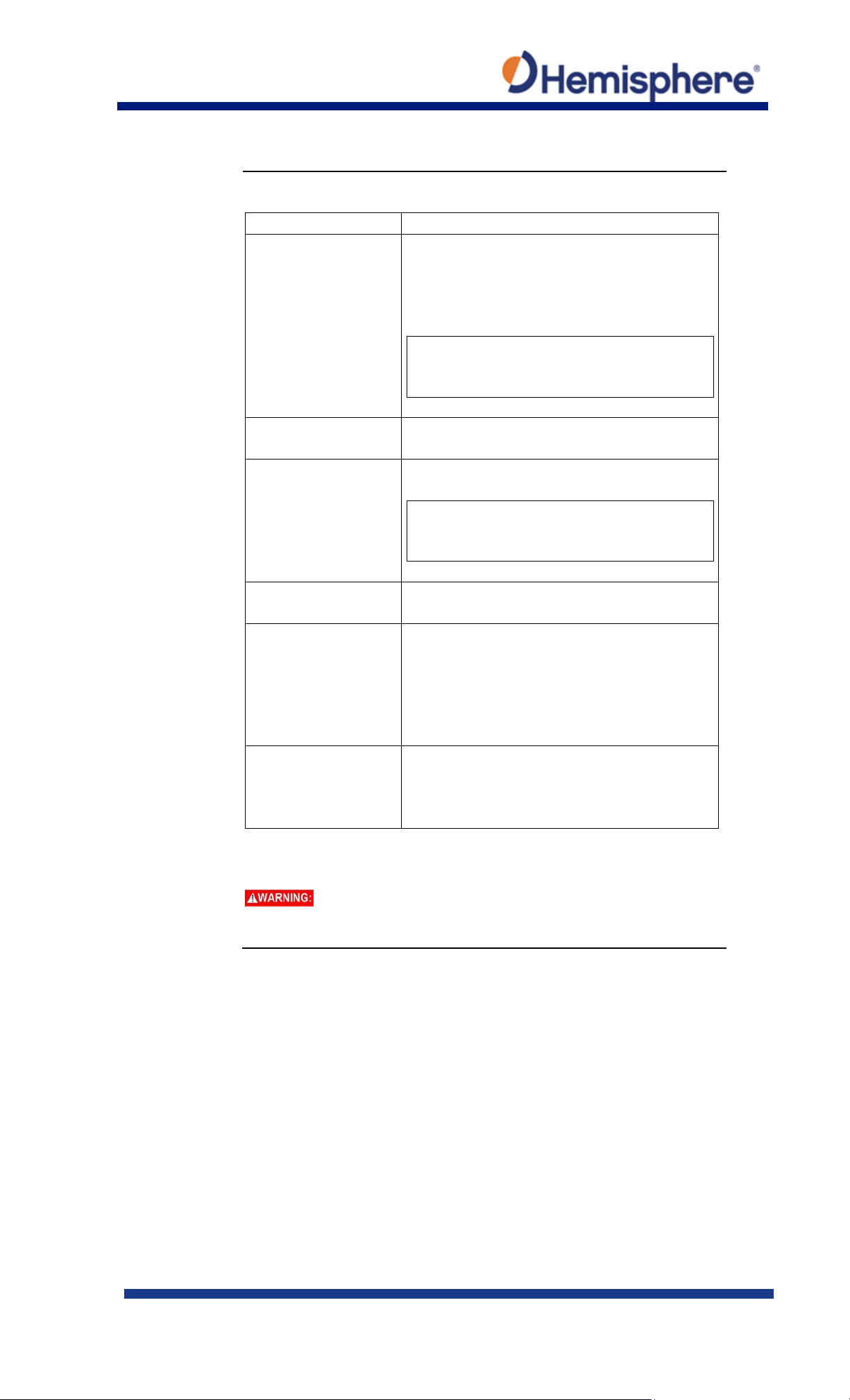
Logging,
Table 7: Logging configuration (continued)
Field
Description
Ephemeris*
receiver.
Log raw GNSS ephemeris messages at 0.2Hz,
Corrections
Log the correction messages coming into
the receiver.
High Speed
High Speed logs diagnostic data.
Duration
Set the period for which you wish to record
data.
File Splitting
Automatically closes a file and restarts a
of all data.
Filename
Choose a filename.
appended date and timestamp.
log, the log file will become corrupted.
Configuring the VR1000 Using the WebUI, Continued
continued
*This feature is only
available if you have a
“Raw” activation on the
1Hz, 10Hz, or 20HZ.
Note: 10Hz and 20Hz are only available with
activations (some kits may come with 10Hz
or 20Hz included).
Note: Selecting that dropdown option
forces the GGA, “corrections” and
“ephemeris” options on.
new file after a period of time.
Use file splitting to decrease file sizes or to
prevent the loss of a file resulting in the loss
All filenames automatically have an
To stop logging, de-select the Enabled button and press Save
Settings.
If you power off the receiver without properly closing a
Continued on next page
875-0422-10 Vector VR1000 QRG Rev A1
March 29, 2019 Page 29 of 36
Page 30
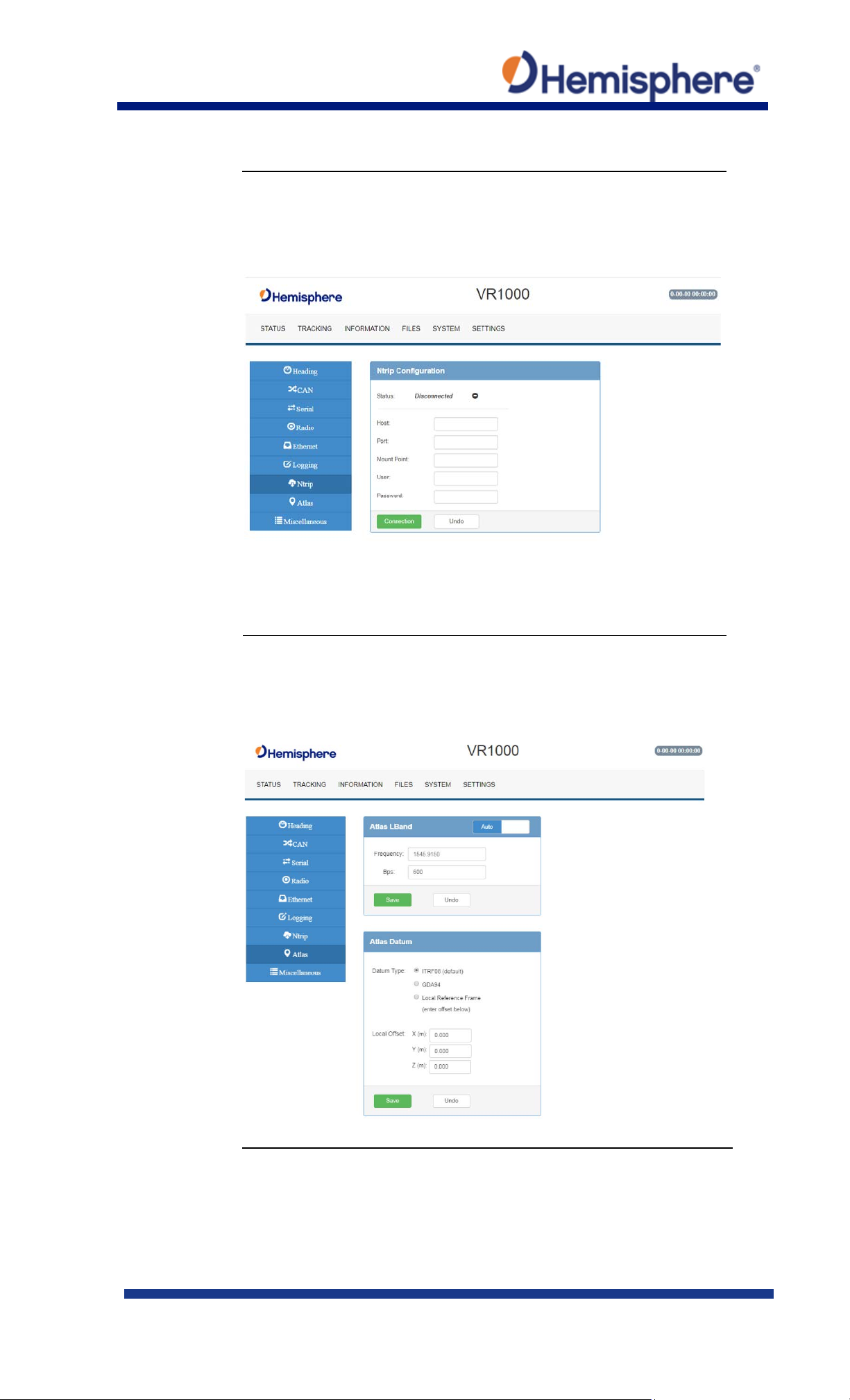
Ntrip
Use the Ntrip Configuration screen to enable the receiver to use
Atlas tab
You can manually configure the frequency and bandwidth of the L-
Configuring the VR1000 Using the WebUI, Continued
Configuration
corrections from an Ntrip Caster.
band satellite you wish to track, or simply click the Auto button and
let the receiver track automatically.
Continued on next page
875-0422-10 Vector VR1000 QRG Rev A1
March 29, 2019 Page 30 of 36
Page 31
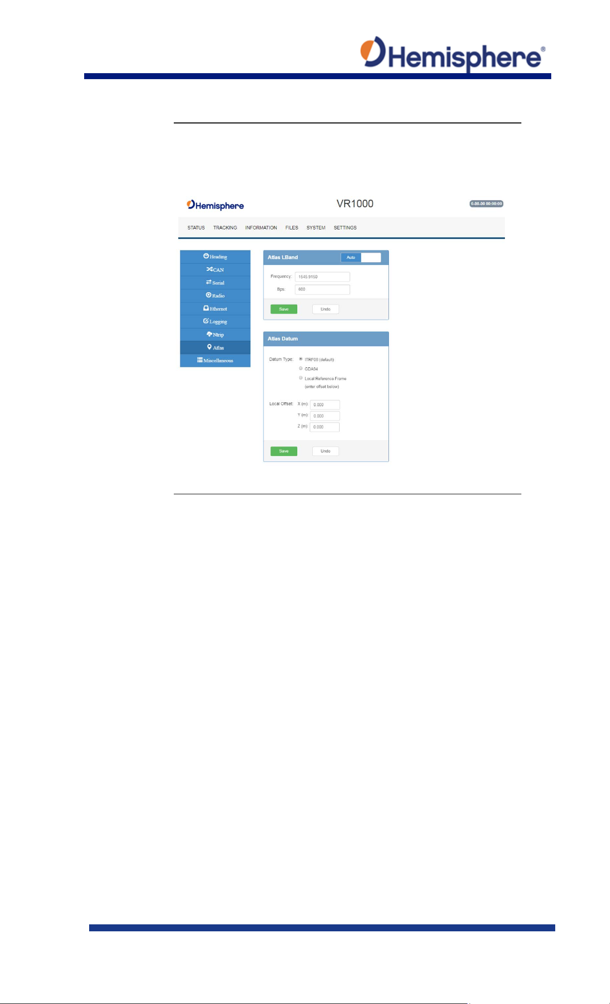
Atlas Datum
If using Atlas (not RTK), datum defaults to ITRF08.
Configuring the VR1000 Using the WebUI, Continued
You can change Datum Type to GDA94 or enter custom reference
frame offsets.
Continued on next page
875-0422-10 Vector VR1000 QRG Rev A1
March 29, 2019 Page 31 of 36
Page 32
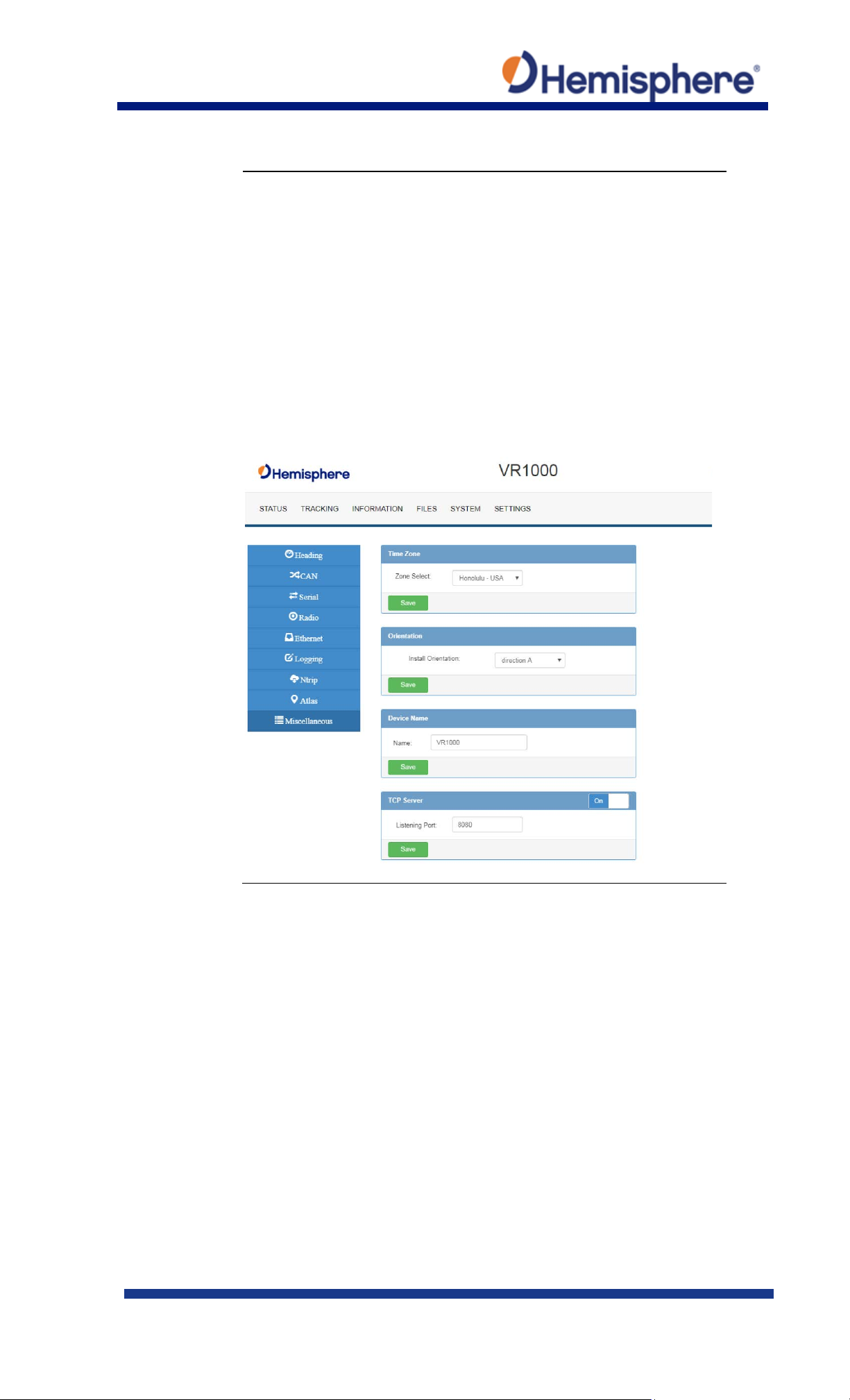
Miscellaneous
Time Zone- In the example below, the Time Zone is set to UTC-10,
Configuring the VR1000 Using the WebUI, Continued
Honolulu - USA time.
To change the Time Zone, click the down arrow, and select the
desired time zone. Please note this does not affect UTC time in
NMEA output.
Orientation-selects the position in which the receiver is installed.
Device Name-the name of device that displays at the top of the
screen.
TCP Server-use to change the listening port.
Continued on next page
875-0422-10 Vector VR1000 QRG Rev A1
March 29, 2019 Page 32 of 36
Page 33
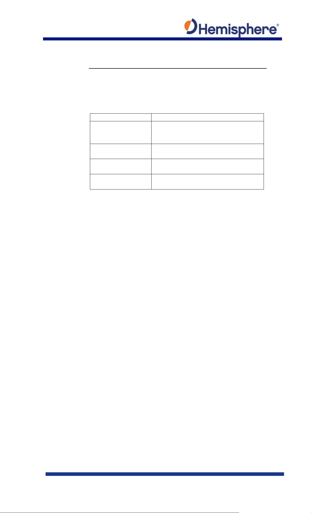
Terms and
Refer to Table A-1 for a listing of the terms and definitions contained
Term
Definition
Atlas Frequency
The Atlas™ satellite transmit frequency
MHz.
Bit Error Rate
The average number of symbol errors per
message frame.
Carrier Lock
Indicates the receiver is tracking the
satellite frequency.
Frame Sync
Indicates the receiver is properly decoding
the Atlas™ data message.
Appendix A
definitions
in this document.
Table A-1: Terms and Definitions
which ranges from 1525 MHz to 1560
875-0422-10 Vector VR1000 QRG Rev A1
March 29, 2019 Page 33 of 36
Page 34
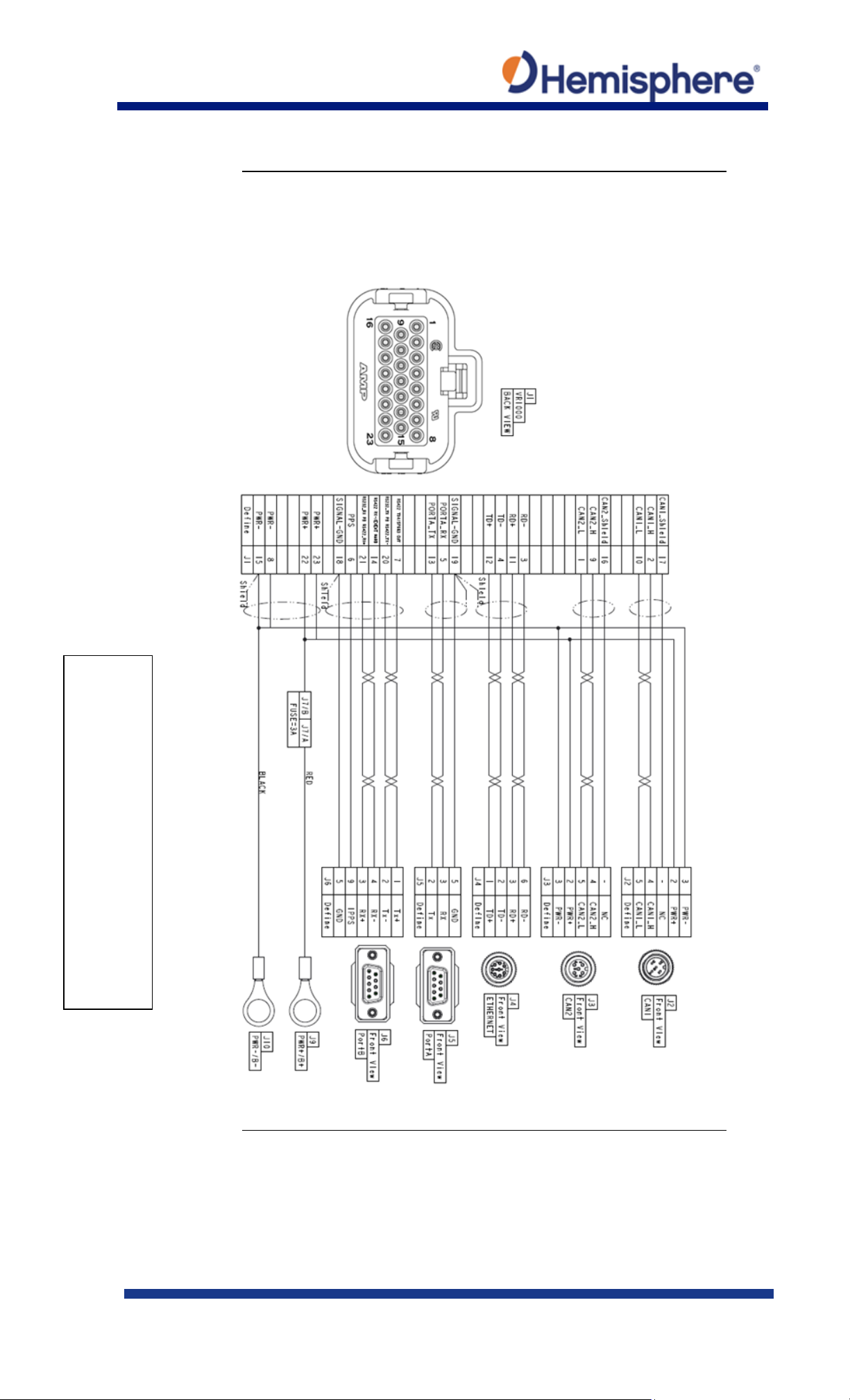
Figure B-1 Cable Drawing
Appendix B
Figure B-1 shows the VR1000 Cable Pin-out assignments.
Note: This cable is not available for purchase.
875-0422-10 Vector VR1000 QRG Rev A1
March 29, 2019 Page 34 of 36
Continued on next page
Page 35
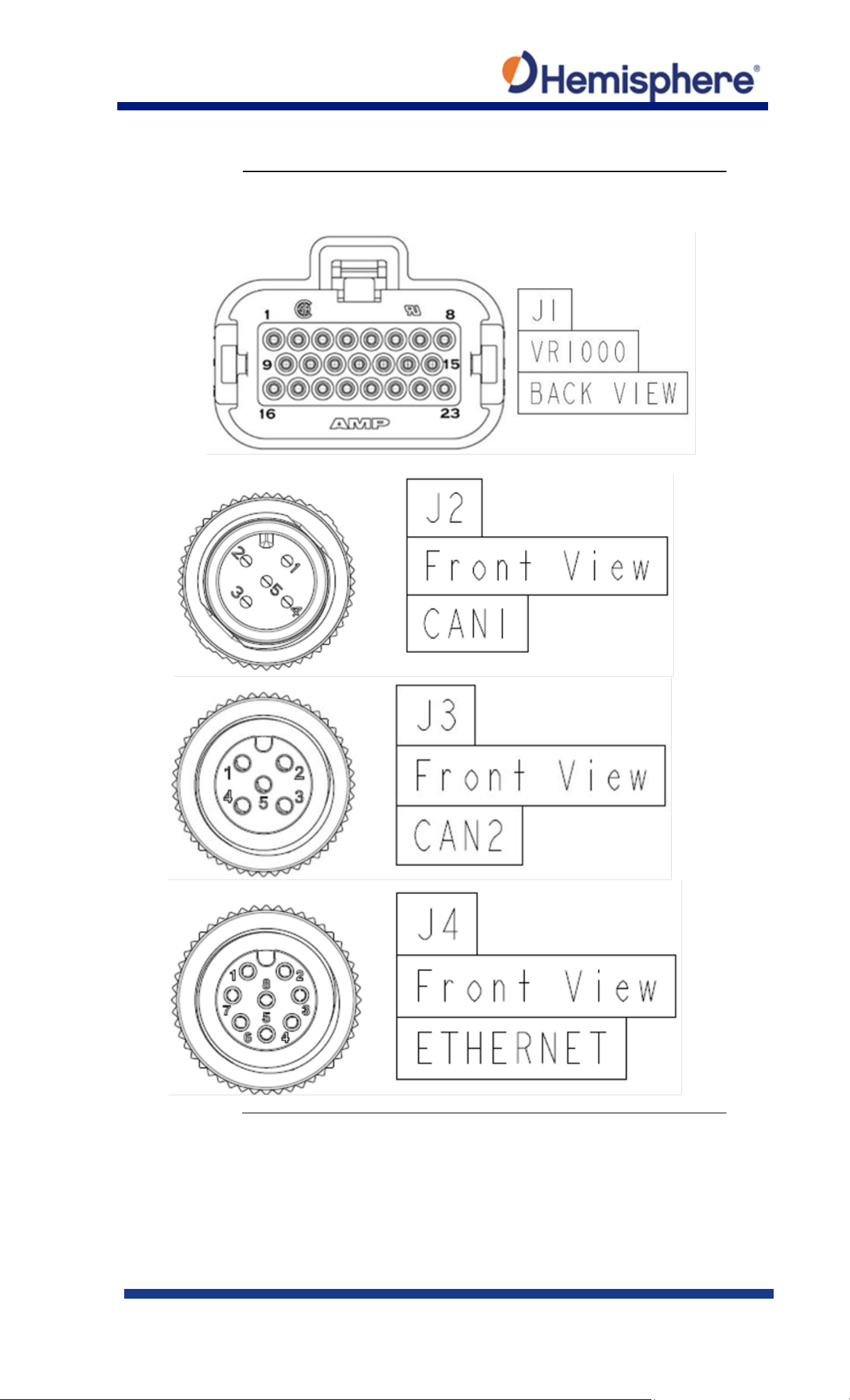
Appendix B, Continued
Figure B-2 shows the pin assignments for the J1 – J6 connectors.
Continued on next page
875-0422-10 Vector VR1000 QRG Rev A1
March 29, 2019 Page 35 of 36
Page 36
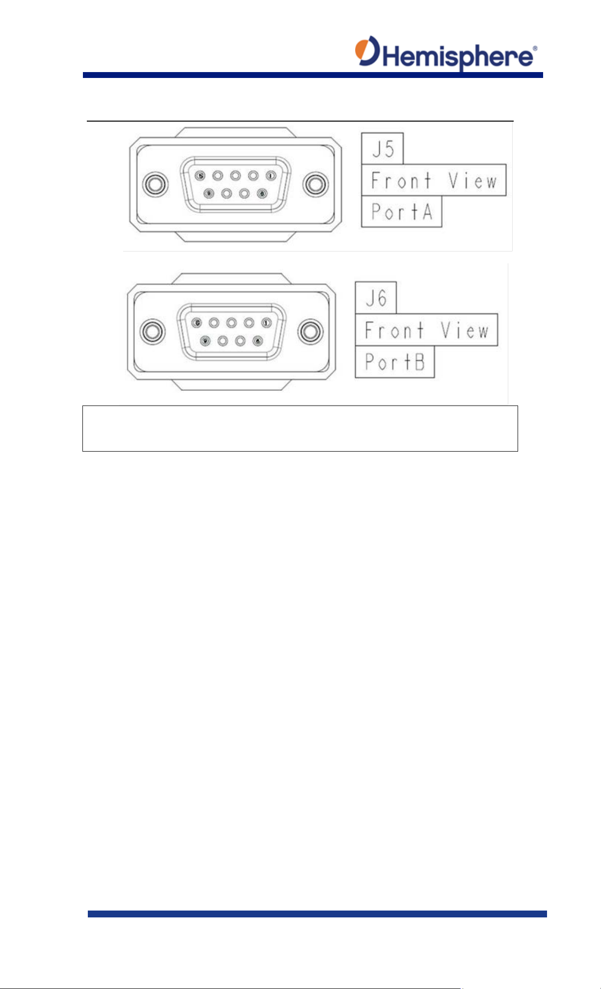
Appendix B, Continued
Figure B2: J1 – J6 Connectors
875-0422-10 Vector VR1000 QRG Rev A1
March 29, 2019 Page 36 of 36
 Loading...