

HEMCO CE 13094, CE 13694, CE 14894, CE 17294, SE 45414 Installation, Operation, Maintenance Manual Instructions
...
Motors are properly lubricated at the time of manufacture. It is not necessary to lubricate at the time of installation unless the
motor has been in storage for a period of 12 months or longer (refer to lubrication procedure that follows)
LUBRICATION PROCEDURES
1.Stop motor. Disconnect power and lock out of service.
2 Remove contaminants from grease inlet area.
3. Remove fi lter and drain plugs.
4. Check fi lter and drain holes for blockage and clean as necessary.
5. Add proper type and amount of grease. See the Relubrication Time intervals Table for service schedule and Relubrication
Amounts Table for volume of grease required.
6. Wipe off excess grease and replace fi ller and drain plugs (see following warning).
7. Motor is ready for operation.
NOTE
If lubrication instructions are shown on the motor nameplate, they will supersede the general instruction.
Motors are pre greased with a mineral oil poly urea NGL! grade 2 type grease unless stated other wise on the motor nameplate. Some compatible brands of mineral polyurea base type grease are: Chevron SRI #2, Rykon
Premium #2, Shell Oil Dolium R, Texaco Polystar RB, or Polyrex EM.
WARNING
!
If motor is nameplated for hazardous locations, do not operate motor without all of the grease or drain plugs
installed.
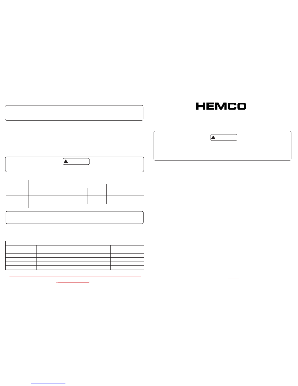
RELUBRICATION TIME INTERVAL
(For motors with regreasing provisions)
Service Condi-
tion and less
NEMA FRAME SIZE
140 - 180 210 - 360 400 - 510
1800 RPM Over 1800
RPM
1800 RPM
and less
Over 1800
RPM
1800 RPM
and less
Over 1800
RPM
Standard 3 years 6 months 2 years 6 months 1 year 3 months
Severe 1 year 3 months 1 year 3 months 6 months 1 month
Seasonal See Note 2
NOTE: 2
1. For motors nameplated as “belted duty” only divide the above intervals by 3.
2. Lubricate at the beginning of the season. Then follow service schedule above.
SEASONAL SERVICE: The motor remains idle for a period of 6 months or more.
STANDARD SERVICE: Up to 16 hours of operation per day, indoors, 40 degrees Celsius maximum ambient.
SEVERE SERVICE: Greater than 16 hours of operation per day. Continuos operation under high ambient temperatures
( 40 to 65.5 degrees Celsius) and / or any of the following: dirty, moist locations, high vibration (above NEMA standards),
heavy shock loading, or where shaft extension end is hot.
RELUBRICATION AMOUNTS (For motors with regreasing provisions)
NEMA Frame Size Volume cu. in. (fl uid oz.) NEMA Frame Size Volume cu. in. (fl uid oz.)
140 .25 (.14) 320 1.50 (.83)
180 .50 (.28) 360 1.75 (.97)
210 .75 (.42) 400 2.25 (1.2)
250 1.00 (.55) 440 2.75 (1.5)
280 1.25 (.69) 500 3.00 (1.7)
Phone (816) 796-2900
Fax. (816) 796-3333
Email info@HEMCOcorp.com
HEMCO Corporation
711 S. Powell Road
Independence MO, 64056
MM-EXP EXHAUST.01.14
Visit www.HEMCOcorp.com Call Toll Free: (800) 779-4362
Lab Planning Solutions
HEMCO
R
Installation, Operation, Maintenance Manual Instructions for
Fume Hood Models with Explosion Proof Exhaust
CE Model #s 13094, 13694, 14894, 17294
SE Model #s 45414, 45514, 45614, 45814
These instructions must be followed to ensure safe and proper installation, operation and maintenance of the motor. They
should be brought to the attention of all persons who install, operate or maintain this equipment.
Failure to follow instructions and safe electrical procedures could result in serious injury or fatality. Disconnect all power and
discharge all capacitors before servicing. Install and Ground per local and national codes. Consult qualifi ed personnel with
questions or if repairs are required.
INSTALLATION
UNCRATING AND INSPECTION
After uncrating, check for any damage which may have been incurred in handling. The motor shaft should turn freely by
hand. Repair or replace any loose or broken parts before attempting to use motor. Check to be sure that motor has not
been exposed to dirt, grit, or excessive moisture in shipment or storage before installation. Measure insulation resistance
(see operation). Clean and dry the windings as required. Never start a motor which has been wet without having it thoroughly dried.
SAFETY
Motors should be installed, protected and fused in accordance with latest issue of the National Electrical Code, NEMA Standard Publication No. MG 2 and local codes.
Eyebolts or lifting lugs are intended for lifting the motor only. These lifting provisions should never be used when lifting or
handling the motor with other equipment (i.e. pumps, gear boxes, fans or other driven equipment) as a single unit. Be sure
the eyebolt is fully threaded and tight in its mounting hole.
Eyebolt lifting capacity rating is based on lifting alignment coincident with the eyebolt center line. Eyebolt capacity decreases as deviation from this alignment increases. See NEMA MG 2.
Frames and accessories of motors should be grounded in accordance with National Electrical Code
(NEC) Article 430. For general information on grounding refer to NEC Article 250.
Rotating parts such as pulleys, couplings, external fans, unusual shaft extensions should be permanently guarded. Keep
hands and clothing away from moving parts. Electrical repairs should be made by trained, qualifi ed personnel only.
LOCATION
In selecting a location for the motor, consideration should be given to environment and ventilation. A motor with the proper
enclosure for the expected operating condition should be selected.
The ambient temperature or the air surrounding the motor shall not exceed 40 degrees Celsius (104 degrees Fahrenheit)
unless the motor has been especially designed for high ambient temperature applications. The free fl ow of air around the
motor should not be obstructed.
The motor should never be placed in a room with a hazardous process, or where fl ammable gases or combustible material
may be present, unless it is specifi cally designed for this type of service.
1. Drip proof (open) motors are intended for use indoors where atmosphere is relatively clean, dry and noncorrosive.
2. Drip proof (open) fi re pump motors are to be installed in a Type 2 drip proof environment as defi ned in NEMA 250.
3. Totally enclosed motors may be installed where dirt, moisture and corrosion are present.
4. Totally enclosed-severe duty motors are recommended for extreme environmental conditions.
5. Explosion proof motors are built for use in hazardous locations as indicated by Underwriters’ label on motor Consult UL,
NEC, and local codes for guidance.
V-BELT DRIVE
1. Align sheaves carefully to avoid axial thrust on motor bearing. The drive sheave on the motor should be positioned toward the motor so it is as close as possible to the bearing.
2. When adjusting belt tension, make sure the motor is secured by all mounting bolts before tightening belts.
3. Adjust belt tension to belt manufactures recommendations. Excessive tension will decrease bearing life.
4. Sheaves should be in accordance to NEMA Spec. MG-1 or as approved by the manufacturer for a specifi c application.
WARNING
!
Phone (816) 796-2900
Fax. (816) 796-3333
Email info@HEMCOcorp.com
HEMCO Corporation
711 S. Powell Road
Independence MO, 64056
Visit www.HEMCOcorp.com Call Toll Free: (800) 779-4362
Lab Planning Solutions
HEMCO
R
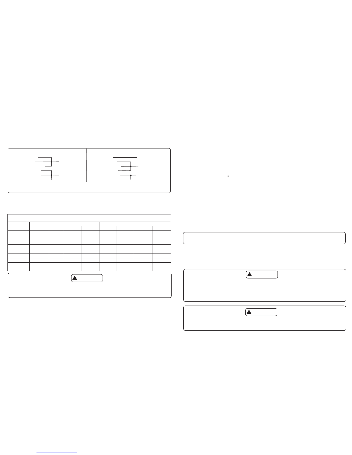
ELECTRICAL CONNECTIONS
1. All wiring, fusing, and grounding must comply with National Electrical codes.
2. To determine proper rotation and voltage connections, refer to the information and diagram on the nameplate, separate
connection plate, or decal. If the plate or decal has been removed, contact the manufacturer for assistance.
3. Use the proper size of line current protection and motor controls as required by the National Electrical Code, and local codes.
Recommended use is 125% of full load amps as shown on the nameplate for motors with 40 degrees Celsius ambient and
a service factor over 1.0. Recommended use is 115% of full load amps as shown on the nameplate for all other motors.
Do not use protection with larger capacities than recommended. Three phase motors must have all three phases protected.
WARNING
!
P1 LINE 1
RED
P2 INSULATE
ORANGE
BLACK
WHITE LINE 2
YELLOW
L
O
W
V
O
L
T
H
I
G
H
V
O
L
T
P1 LINE 1
P2 INSULATE
RED
ORANGE INSULATE
WHITE
BLACK LINE 2
YELLOW
Rotation CCW - OPE To Reverse Either
Voltage Interchange Black and Red Leads
CHANGING ROTATION
1. Keep hands and clothing away from rotating parts.
2. Before the motor is coupled to the load, determine proper rotation.
3. Check rotation by jogging or bumping. Apply power to the motor leads for a short period of time, enough to just get motor
shaft to rotate a slight amount to observe shaft rotating direction.
4. Three phase - interchange any (2) of the three (3) line leads. Single phase - reconnect per the connection diagram on
the motor
Wire Size for 115 & 230 Volt Single Phase Circuits
Distance - Motor to Fuse or Meter Box - Feet
Motor
HP
100 Ft. 200 Ft. 300 Ft. 500 Ft.
115V 230V 115V 230V 115V 230V 115V 230V
1/4 #14 #14 #10 #12 #8 #10 #6 #8
1/3 #12 #14 #10 #12 #6 #10 #4 #8
1/2 #10 #12 #8 #10 #6 #8 #4 #6
3/4 #10 #12 #6 #10 #4 #8 #2 #6
1 #8 #10 #6 #8 #4 #6 #4
1 1/2 #4 #10 #0 #8 #6 #4
2#8#6#4#2
3#8#6#4#2
5#6#4#2#0
Disconnect power before working on motor driven equipment
Motors with automatic thermal protectors will automatically restart when the protector cools. Do not use motors with
automatic thermal protectors in applications where automatic restart will be hazardous to personnel or equipment.
Motors with manual thermal protectors may start unexpectedly after the protector trips. If manual protector trips. disconnect
motor from power line. After protector cools (fi ve minutes or more) it can be reset and power may be applied to the motor.
THERMAL PROTECTOR INFORMATION
The nameplate will indicate one of the following:
1. Motor is thermally protected
2. Motor is provided with overheat protective device.
For Example:
1. Motors without thermal protection will have nothing stamped on nameplate about thermal protection.
2. Motors equipped with built-in thermal protection have “THERMALLY PROTECTED” stamped on the nameplate. Thermal
protectors open the motor circuit electrically when the motor overheats or is overloaded. The protector cannot be reset until
the motor cools. If the protector is automatic, it will reset itself, If the protector is manual, press the red button to reset.
3. Motors that are provided with overheat protective device that does not open the motor circuit directly will indicate “ WITH
OVERHEAT PROTECTIVE DEVICE:. See motor connection diagram for details.
REDUCED VOLTAGE STARTING
Motors used on reduced voltage starting, should be carefully selected based upon power supply limitations and driven load
requirements. The motors starting torque will be reduced when using reduced voltage starting. The elapsed time on the start
step should be kept as short as possible and should not exceed 5 seconds. It is recommended that this time be limited to 2
seconds. Refer to the manufacturer for application assistance.
OPERATION
BEFORE INITIAL STARTING
1. If a motor has become damp in shipment or in storage, measure the insulation resistance of the stator winding.
Minimum Insulation Resistance = 5 Megaohlms ( use 500 volt megger)
Do not attempt to run motor if the insulation resistance is below this value. Have the motor inspected, dried and/ or cleaned.
Contact a qualifi ed motor repair shop.
2. See that voltage and frequency stamped on motor and control nameplates correspond with that of the power line.
3. Check all connections to the motor and control with the wiring diagram.
4. Be sure rotor turns freely when disconnected from the load. Any foreign matter in the air gap should be removed.
5. Leave the motor disconnected from the load for the initial start ( see following instructions). Check for proper rotation.
Check for correct voltage ( within + 10% of nameplate value) ant that is balanced within 1% at the motor terminals. After the
machine is coupled to the load, check that the nameplate amps are not exceeded. Recheck the voltage level and balance
under load per the above guidelines.
Shut down the motor if the above parameters are not met or if any other noise or vibration disturbances are present. Consult
NEMA guidelines or the equipment manufacturer if any questions exist before operating equipment.
ALLOWABLE VOLTAGE AND FREQUENCY RANGE
If voltage and frequency are within the following range, motors will operate , but with somewhat different characteristics than
obtained with correct nameplate values.
1. Voltage : Within 10% above or below the value stamped on the nameplate. On three phase systems the voltage should be
balanced within 1%. A small voltage unbalance will cause a signifi cant current unbalance.
2. Frequency: Within 5% above or below the value stamped on the nameplate.
3. Voltage and Frequency together: Within 10% ( providing frequency above is less than 5%) above or below values stamped
on the nameplate.
CLEANLINESS
Keep both the interior and exterior of the motor free from dirt, water , oil and grease. Motors operating in dirty places should
be periodically disassembled and thoroughly cleaned.
NOTE
Motors should be disassembled only by an authorized service station
DO NOT disassemble hazardous duty motors, see warning below
CONDENSATION DRAIN PLUGS
All explosion proof and some totally enclosed motors are equipped with automatic drain plugs, they should be free of oil,
grease, paint, grit, and dirt so they don’t clog up. The drain system is designed for normal fl oor (feet down) mounting. For
other mounting positions, modifi cations of the drain system may be required, consult the manufacturer.
SERVICE
WARNING
!
1. Motors nameplated for hazardous locations should be disassembled only by the original equipment manufacturer or by a facility that is UL listed under UL’s category: “ Motors & Generators, Rebuilt for Use in Hazardous
Locations”.
2. Disconnect power before working on motor or driven equipment. Motors with automatic reset thermal protectors will automatically restart when the protector cools. Do nor use motors with automatic reset thermal protectors in applications where automatic restart will be hazardous to personnel or equipment.
CAUTION
!
Over Greasing bearings can cause premature bearing and / or motor failure. He amount of grease added should
be carefully controlled.
 Loading...