

Page 1
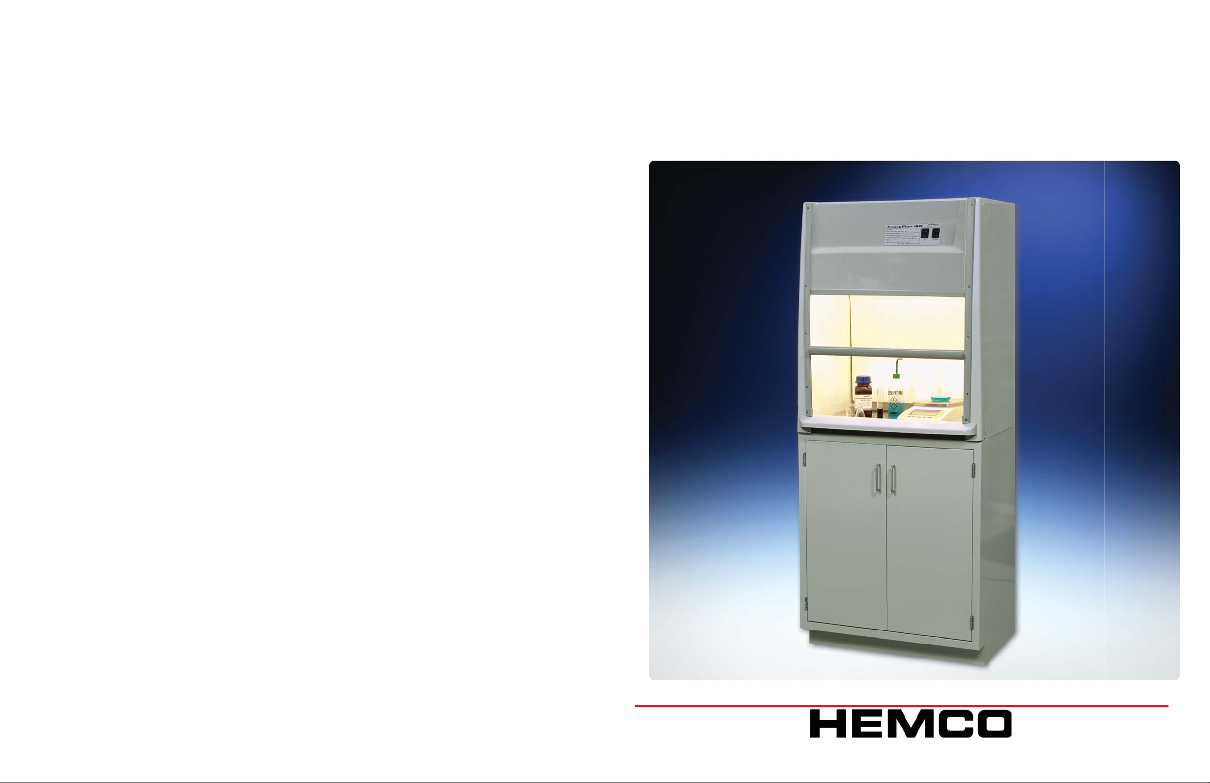
Installation, Operation, Maintenance Manual
EcoFlow Laboratory Fume Hood
Model # s
92011, 92012, 93011,93012,90311, 90312, 90411,90412,
Visit www.HEMCOcorp.com Call Toll Free: (800) 779-4362
HEMCO Corporation
711 S. Powell Road
Independence MO, 64056
Phone (816) 796-2900
Fax. (816) 796-3333
Email [email protected]
Page 2

The HEMCO fume hoods are shipped palletized, fully crated, padded and wrapped for maximum protection
and ease of handling. If damaged call the adjuster for the delivering carrier promptly and notify HEMCO at
(816) 796-2900.
• Upon receiving, inspect for crate damage and possible concealed damage that may have occurred in
transit. Save all delivery receipts and crating materials. If damaged call the adjuster for the delivering carrier
promptly and notify HEMCO at (816)796-2900.
• When uncrating the fume hood remove the band strap, which is securing the corrugate to the pallet.
• When ready to install fume hood, carefully lift from pallet and set on work surface in proper location (see
fume hood Installation).
CAUTION: DO NOT lift the fume hood at any time by the airfoil as this will damage the unit.
SITE PREPARATION
A fume hood requires that it be installed on a level surface. If fume hood base cabinets are included with the
fume hood installation make sure the fl oor is clean and level.
All service lines for the Fume hood installation, such as water, air, gas, etc. should be purged of dirt, capped
and tested prior to connection to the fume hood.
Laboratory fume hoods should be located to avoid cross-currents at the fume hood face due to heating,
cooling or ventilation inlets.
Fume hoods should be located away from high traffi c lanes within the lab to avoid air that could draw haz-
ardous fumes into the room.
Passing personnel should provide suffi cient aisle space in front of the fume hood to avoid disruption of the
work or interference with the operating technician.
Safety devices such as drench showers, eyewash stations, fi re extinguishers, fi rst aid kits and fi re blankets
should be located convenient to the fume hood operating personnel and plainly labeled as to their use and
function.
In addition, laboratory fume hoods are potential locations for fi res and explosions due to the type of experi-
ments conducted in these units. As such, fume hoods should be located so an explosion or fi re within the
hood would not impede exit from the lab.
BASE CABINET INSTALLATION
Position the cabinets in the desired location approximately 7 inches from a rear wall or in a suitable island
location. Top of the cabinet should be leveled using the adjustment feet on the bottom of the cabinet. If multiple cabinets are involved, bolt together and to existing cabinets or walls and level as one unit.
Page 3

Fume Hood Operation
Safety considerations require that a schedule of inspections and documentation be set up for
every laboratory fume hood.
An inspection record should be maintained. This record may be in the form of a label attached
to the fume hood or a log maintained by the laboratory director or safety offi cer.
WORK SURFACE INSTALLATION
Once the fume hood base cabinet is installed, apply an adhesive to the top surface of the cabinet. Carefully place work surface on cabinet and make any corrections the position/alignment. Allow adhesive to
dry before setting fume hood.
FUME HOOD INSTALLATION
1. Fume hood must be set on a work surface or a fl at level surface, supported by a base cabinet or
table. The Fume hood is a lab furnishing and shall NOT be installed in the walls, ceiling or any other
structural feature of the building.
Inspection procedures should include instrument verifi cation of fume hood face velocity
performance and usage by observations and interview.
Procedures should consist of a physical examination of liner condition and cleanliness, baffl e
and sash operation and condition, sash cable and guide wheels, and service fi xture function.
All results should be recorded and reported to the proper authority for any required action.
NOTE: Special purpose fume hoods such as those used with radioactive materials or perchloric
acids require additional inspection procedures to cover special equipment and requirements.
Options, such as airfl ow monitors or other types of monitors should be inspected annually.
Fume hood air face velocity is an important consideration. 100 feet per minute (FPM) is the
standard requirement. Velocities in excess of 150 FPM may reduce fume hood performance and
create hazardous condition(s).
The establishment of the proper face velocity for a specifi c laboratory fume hood should be
based on a number of factors. The nature of the fumes emitted from the hood is of obvious
importance.
2. DO NOT lift the fume hood at any time by the airfoil as this will damage the unit.
3. Once the fume hood is in place, service lines can be connected (See Electric and Plumbing).
4. Service panels are provided to allow access for service hookup. Outer service panels are removed by
gently prying the inner panel away from the outer trim ring at the clearance spots. Inner service panels
are removed by unlocking the locking spline of the rubber sealing gasket creating tolerance to remove
the gasket and inner panel. Panels may be set aside for later replacement after the installation is complete. The front access panel above the sash is removable to allow access to the top of the fume hood
(pull out on lower edge of upper most panel and push up to remove). The electrical junction box, light
fi xture, outlet collar for duct connection,and special plumbing connections, can be accessed / installed
from this position.
5. Fume hoods are equipped with a clear acrylic sash. The sash slides in a PVC track that is contoured
to the front of the hood. Friction screws are located in the track allowing for adjustment of sash movement.
6. The incandescent light fi xture is factory mounted.
NOTE: Bulbs are not provided with the Fume Hood. For those fume hoods with vapor-proof incan-
descent light(s), unscrew the glass globe install bulb and replace globe.
Consult your company safety department for recommendations covering the materials you plan
on using.
Cross-drafts, created by the room ventilation system or from an open window or corridor, if
located adjacent to the hood, can drastically disturb the fl ow of air entering the fume hood face
and even cause a reverse fl ow of air out of the front of the hood. Room conditions such as these
should be avoided. The velocity of the cross drafts should not exceed 20 percent of the fume
hood face velocity.
Your Laboratory Safety Plan and Company Procedures should combine to create a safe and
healthful work environment.
NOTE: In those areas where seismic codes are a consideration, it is recommended that qualifi ed
engineers be consulted for necessary installation requirements for seismic codes.
ELECTRICAL
Electrical services supplied with your fume hood are factory mounted wired to junction box on top of the
fume hood. Final wiring must be completed by a licensed electrician to comply with local codes.
Supply wiring requirements:
• 20 amperes circuit use 12 gauge wire and 14 gauge ground wire size.
• 15 amperes circuit use 14 gauge wire and 14 gauge ground wire size.
It is required that the main junction box be grounded and that an external disconnect device, circuit
breaker, and/or over-current device be located in the power source supply wiring, and be provided in
close proximity to the fume hood. This disconnect device shall be marked as the disconnect device for
the fume hood and easily accessible.
Page 4

PLUMBING
CAUTION: All service fi xtures requiring plumbing are normally installed on the fume hood ready for con-
nection to the service outlets. Piping should have a solvent and corrosion resistant fi nish. Piping should
be the best material for material being conveyed. Material types are typically copper, stainless steel, black
pipe, galvanized pipe, CPVC, and PVC. A certifi ed plumber should be used for all installation. Installation
shall be installed in compliance with Local and NFPA Standards.
TROUBLE SHOOTING
PROBLEM CAUSE CORRECTIVE ACTION
Not limited to the following:
• Fuel gases such as manufactured, natural, and LP-Gas – National Fuel Gas Code, NFPA 54, and the
Liquefi ed Petroleum Gas Code, NFPA 58.
• Hydrogen – Standard for Gaseous Hydrogen Systems at Consumer Site, NFPA 50A.
• Acetylene, oxygen systems – Standard for Design and Installation of Oxygen-Fuel Gas Systems for
Welding, Cutting, and Allied Processes, NFPA 51.
BLOWERS
If your Fume Hood was ordered with an integral blower, it will be mounted on the fume hood. It will be
necessary to wire it per local codes. Depending on the types of fumes being exhausted and the length of
the ductwork, rigid PVC, fl exible neoprene, sheet metal or stainless ducting must be attached for fume
removal.
CAUTION: The maximum length of run of ducting with integral blowers should be 10' or less to minimize
static pressure loss.
Remote mounted blowers and ducting requirements other than as specifi ed are site specifi c and require
a qualifi ed engineer or installer. The exhaust system and ducting should be protected from corrosion or
inherently corrosion resistant.
CLEAN UP
Upon completion of the installation of your fume hood it is a good idea to clean thoroughly to eliminate
any miscellaneous debris and/or surface soil.
1. For all composite surfaces use a general-purpose nonabrasive household cleaner.
2. For glass surfaces use a formula glass cleaner. (Windex).
3. For the work surface it is recommended that you use soap and water.
4. For metal cabinet painted surfaces use a general purpose nonabrasive cleaner,
1) Improperly sized blower
2) Motor (impeller wheel) is
Insuffi cient air fl ow
Fume Hood or Blower
not operating
Contaminates outside
fume hood face
Sash binding
Air Flow Monitor 6) 7)
running backwards
3) Obstruction in duct system
4) Leaks in duct system
5) Overloaded fi lters
1) Blown fuse or open circuit
breaker
2) Defective motor
3) Thermal protector on
4) Motor improperly wired
1) Improper use or procedures
2) External factors
3) Improper face velocity
4) Cable off of pulley
Cable Broke
1) Resize blower, change
drive package
2) Correct wiring for reverse
rotation of motor.
3) Locate and Remove obstruction
4) Trace and repair
5) Clean or replace fi lters
1) Replace fuse or reset
circuit breaker
2) Consult factory
3) Check for high or low voltage input or ambient temperatures over 40 degree C
( 104 degree F)
4) Correct wiring for reverse
rotation of motor
1) Follow safety guidelines
and procedures
2) Check external air fl ow
patterns around fume hood
3) Recertify fume hood face
velocity and/or duct system
5) Replace Sash / Cable
Any questions? Call HEMCO customer service at (816) 796-2900.
Electrical Services
not working
8) Circuit Breaker
10)Corroded Contacts
9) Check Main Load Center
11)Clean or replace
Page 5

SAFETY RECOMMENDATIONS
FUME HOOD OPERATION
Safety considerations require that a schedule of inspections and documentation be set up for every
laboratory fume hood.
DO - AVOID UNNECESSARY EX
POSURE OF PERSONNEL
TO FUMES INSIDE HOOD BY
KEEPING SASH CLOSED
EXCEPT WHEN LOADING OR
UNLOADING HOOD.
DO - KEEP MATERIALS 6" OR
MORE FROM FRONT EDGE
OF SASH PLANE.
DO - KEEP THE SASH AT DESIGN
OPENING WHILE UTILIZING
THE FUME HOOD.
DO - CLEAN UP IMMEDIATELY
ANY MAJOR SPILLS OCCUR
RING INSIDE HOOD.
DO - USE ONLY GROUNDED
ELECTRIC EQUIPMENT.
DO - REPORT ANY MALFUNCTION
OF THE EXHAUST SYSTEM.
DO - ELEVATE CONTAMINATES
AND EQUIPMENT ABOVE
WORKSURFACE OF HOOD
ENABLING AIR FLOW BE
NEATH AND AROUND.
DO - KEEP MOVEMENTS IN THE
HOOD AND IN FRONT OF
THE HOOD TO A MINIMUM.
DO NOT - USE HOOD UNLESS EXHAUST
SYSTEM IS IN OPERATION.
DO NOT - CHANGE DAMPER OR BAFFLE
SETTINGS AFTER INITIALLY SET.
DO NOT - USE FUME HOOD FOR STORAGE
OF CORROSIVE OR VOLATILE
MATERIALS.
DO NOT - BLOCK BAFFLE OR GRILL
OPENINGS.
DO NOT - GENERATE LARGE QUANTITIES
OF INFLAMMABLES WITHIN THE
FUME HOOD.
DO NOT - PERMIT TEMPERATURES OF
SASH GLASS TO EXCEED 160
DEGREES FAHRENHEIT.
DO NOT - PLACE UPPER BODY OR HEAD
INSIDE THE FRONT PLANE OF
THE HOOD OPENING.
DO NOT - OPEN OR CLOSE SASH SWIFTLY
AS THIS MAY CAUSE ADVERSE
AIR FLOW CURRENTS.
DO NOT - APPROACH OR LEAVE HOOD
FACE SWIFTLY AS THIS MAY
CAUSE ADVERSE AIR FLOW
CURRENTS.
An inspection record should be maintained. This record may be in the form of a label attached to the
fume hood or a log maintained by the laboratory director or safety offi cer.
Inspection procedures should include instrument verifi cation of fume hood face velocity performance
and usage by observations and interview.
Procedures should consist of a physical examination of liner condition and cleanliness, baffl e and
sash operation and condition.
All results should be recorded and reported to the proper authority for any required action.
NOTE: Special purpose fume hoods such as those used with radioactive materials or perchloric
acids require additional inspection procedures to cover special equipment and requirements.
Options, such as airfl ow monitors or other types of monitors should be inspected annually.
Fume hood air face velocity is an important consideration. 100 feet per minute (FPM) is the standard
requirement. Velocities in excess of 150 FPM may reduce fume hood performance and create hazardous condition(s). The 100 FPM may be at different sash height positions depending on the duct
length and fan size.
The establishment of the proper face velocity for a specifi c laboratory fume hood should be based on
a number of factors. The nature of the fumes emitted from the hood is of obvious importance.
Consult your company safety department for recommendations covering the materials you plan on
using.
Cross-drafts, created by the room ventilation system or from an open window or corridor, if located
adjacent to the hood, can drastically disturb the fl ow of air entering the fume hood face and even
cause a reverse fl ow of air out of the front of the hood. Room conditions such as these should be
avoided. The velocity of the cross drafts should not exceed 20 percent of the fume hood face velocity.
Your Laboratory Safety Plan and Company Procedures should combine to create a safe and healthful work environment.
DO – CHECK FUME HOOD FACE
VELOCITY ON A REGULAR
SCHEDULE.
Page 6

MAINTENANCE
SASH
Standard fume hoods are provided with a type of movable sash or viewing window. The sash should be
cleaned frequently to avoid the possibility of residue building up on the surface. A soft, cloth and mild cleaner should be used for best results.
BLOWER INSPECTION
It is recommended that both the blower motor and blades be periodically inspected. Belt wear, blade corrosion and exhaust port clogs are examples of blower problems that can develop over long-term use.
THE ROOM MAKE-UP AIR DELIVERY SYSTEM
FUME HOOD
Cleaning of fume hoods should include the removal of the baffl e for full cleaning of interior surfaces. Spills
should be fl ushed immediately using neutralizing compounds as required and cleaned thoroughly after-
wards. General cleaning can be done with mild detergents and water.
CABINETS
Although designed for wear and tear, the life of cabinets can be greatly extended through observance of
proper cleaning and maintenance procedures. Drawers that are overloaded, doors misadjusted, and locks
which malfunction can lead to undue stress on equipment, and can permanently affect performance. Metal
casework and hardware should be cleaned periodically with good quality cream furniture Polish or an automotive cleaner and fi nishing wax. Use of rubbing compound often can restore superfi cial abrasions. Spills
should be cleaned up immediately followed by a wash down with detergent and water.
Corrosive reagents should be stored in well ventilated casework specifi cally designed for corrosive storage.
HEMCO offers a complete line of acid/corrosive cabinets and fl ammable/combustible cabinets.
WORKSURFACES
Epoxy Resin - Fine scratches will usually disappear when the top is cleaned with a good quality liquid furniture polish. Mildly abrasive cleaners can be used for stain removal.
Make-up air is a ventilation term describing the bringing in of outdoor air to “supply” the building with air
removed by the exhaust ventilation system, creating a balance. In general, laboratories require eight –
twelve total volume changes per hour. Special applications may require up to 20 air changes per hour.
Make-up air is necessary in any lab with an operating fume hood. A suffi cient quantity of make-up air must
be available to allow fume hoods to develop required face velocities. Consideration must be given to the
make-up air required for air changes in each specifi c laboratory involved.
DUCTING
Ducting should be checked periodically for possible leaks.
FACE VELOCITY - CALIBRATION
Fume hood face velocity should be checked at a minimum annually, recommend checking face velocity biannually and the fi ndings recorded and compared with previous readings. Signifi cant changes in face ve-
locity should be reported and investigated. Changes in face velocity may be caused by supply air changes,
exhaust blower problems, or loose, broken, corroded, or blocked ducting. Recommended test protocol is
at a minimum the face velocity and smoke visualization sections of the ASHRAE 110 – 1995 or current test
procedure.
SERVICE FIXTURES
Fixtures which have been subjected to chemical fumes over a prolonged period of time may show signs of
corrosion. When this occurs thorough cleaning with formulated chrome cleaner followed by an application
of paste wax is recommended.
Epoxy-coated fi xtures used in chemical areas can be cleaned with detergent and water, dried, and lightly
polished with a soft cloth. Do not use abrasive cleaners. High temperatures may alter the color of the plastic
coating on fi xtures; this condition cannot be cleaned away, but the chemical resistance of the fi nish is un-
changed. A break in the plastic coating of these fi xtures should be touched up immediately with matching
paint or lacquer to protect the fi xture.
BLOWER LOCATION AND SIZE
Where the building design permits, the exhaust blower should be located on the roof of the building to provide a negative pressure in the portion of the duct system located within the building. The exhaust blower
should be sized to exhaust the volume of air necessary to attain the selected fume hood(s) design face
velocity at the total system static pressure loss. Blower should also be sized to achieve the lowest practical
rotational speed thereby minimizing noise/vibration.
 Loading...