

Page 1
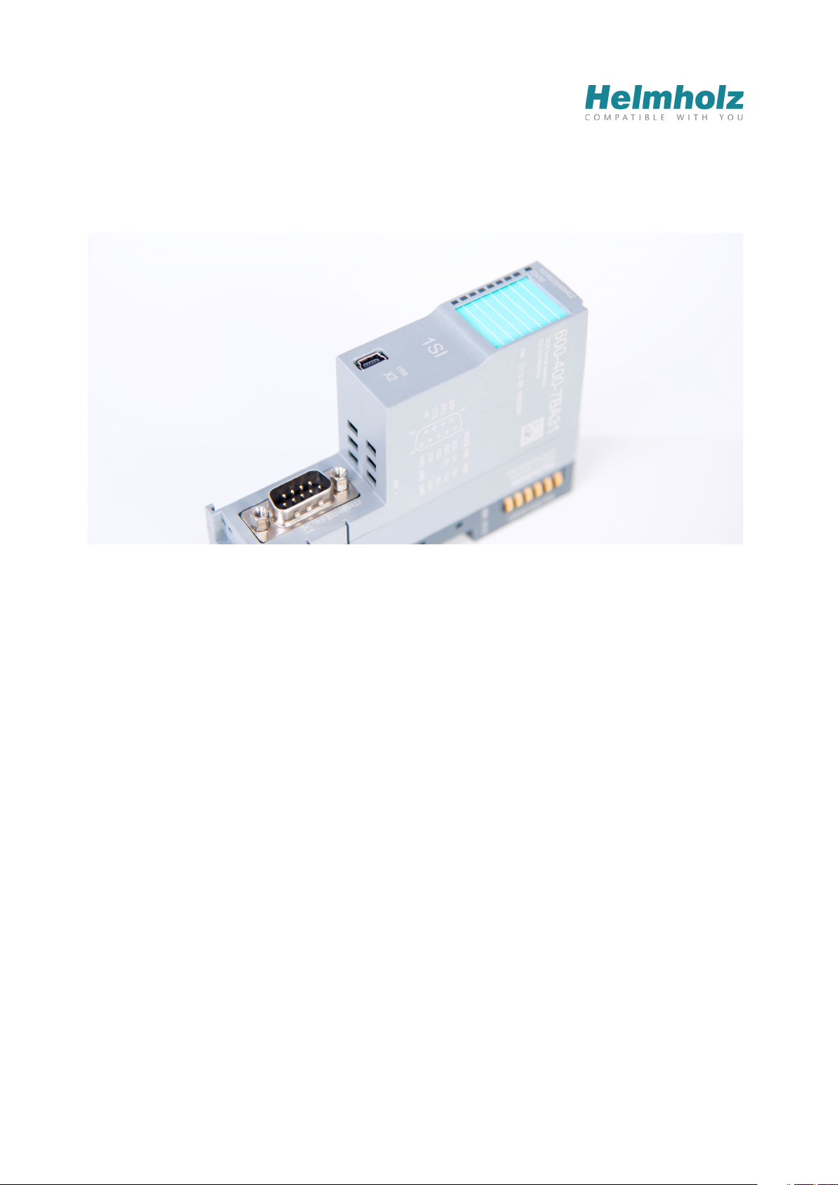
TB20 – Serial interface 1SI
Manual
Version 1 / 10/29/2015 for HW 1 & FW V1.04.000 and higher
Manual order no.: 960-400-7BA31/en
Systeme Helmholz GmbH | Hannberger Weg 2 | D-91091 Großenseebach | Germany
Phone +49 9135 7380-0 | Fax +49 9135 7380-110 | [email protected] | www.helmholz.com
Page 2

Notes
All rights reserved, including those related to the translation, reprinting, and reproduction
of this manual or of parts thereof.
No part of this manual may be reproduced, processed, duplicated, or distributed in any
form (photocopy, microfilm, or any other methods)—even for training purposes or with
the use of electronic systems—without written approval from Systeme Helmholz GmbH.
All rights reserved in the event of the granting of a patent or the registration of a utility
model.
Copyright © 2015 by
Systeme Helmholz GmbH
Hannberger Weg 2, 91091 Großenseebach, Germany
To download the latest version of this manual, please visit our website at
www.helmholz.de.
We welcome all ideas and suggestions.
Trademarks
STEP and SIMATIC are registered trademarks of SIEMENS AG.
Windows is a registered trademark of Microsoft Corporation.
Revision Record
Version Date Change
1 10/16/2015 First version 1SI RS232/RS422/485 Renner 10-5-15
TB20 – Serial interface 1SI | Version 1| 13.03.2019 2
Page 3

Table of contents
General Information .................................................................... 7
1
1.1 Target audience for this manual ................................................................................ 7
1.2 Safety instructions ...................................................................................................... 7
1.3 Note symbols and signal words in the manual ......................................................... 8
1.4 Intended use ............................................................................................................... 9
1.5 Improper use ............................................................................................................... 9
1.6 Installation ................................................................................................................ 10
1.6.1 Access restriction .............................................................................................................. 10
1.6.2 Electrical installation ........................................................................................................ 10
1.6.3 Protection against electrostatic discharges ....................................................................... 10
1.6.4 Overcurrent protection ..................................................................................................... 10
1.6.5 EMC protection ................................................................................................................ 10
1.6.6 Operation .......................................................................................................................... 11
1.6.7 Liability ............................................................................................................................. 11
1.6.8 Disclaimer of liability ....................................................................................................... 11
1.6.9 Warranty ........................................................................................................................... 11
2 System overview ........................................................................12
2.1 General Information ................................................................................................ 12
2.2 The components that make up the TB20 I/O system ............................................. 12
2.2.1 Bus coupler ....................................................................................................................... 12
2.2.2 Peripheral modules ........................................................................................................... 12
2.2.3 Power and isolation module ............................................................................................. 13
2.2.4 Power module ................................................................................................................... 14
2.2.5 Final bus cover .................................................................................................................. 15
2.2.6 Components in a module ................................................................................................. 15
2.2.7 Module Coding ................................................................................................................. 16
3 Installation and removal ............................................................17
3.1 Installation position ................................................................................................. 17
3.2 Minimum clearance ................................................................................................. 17
3.3 Installing and removing peripheral modules .......................................................... 18
3.3.1 Installation ........................................................................................................................ 18
3.3.2 Removal ............................................................................................................................ 19
3.4 Replacing an electronic module ............................................................................... 22
3.5 Installing and removing the coupler ....................................................................... 26
3.5.1 Installation ........................................................................................................................ 26
3.5.2 Removal ............................................................................................................................ 27
TB20 – Serial interface 1SI | Version 1| 13.03.2019 3
Page 4

3.6 Installing and removing the final bus cover ........................................................... 29
3.6.1 Installation ........................................................................................................................ 29
3.6.2 Removal ............................................................................................................................ 29
4 Configuration/wiring .................................................................30
4.1 EMC/safety/shielding ............................................................................................... 30
4.2 Front connectors ...................................................................................................... 31
4.3 Wiring the coupler ................................................................................................... 32
4.4 Using power and isolation modules ........................................................................ 33
4.5 Separate power supply segments for the coupler and the I/O components........... 34
4.6 Using Power Modules ............................................................................................... 35
4.7 Function of the OK-LED ........................................................................................... 36
4.8 Electronic nameplate ................................................................................................ 36
4.9 Fusing ........................................................................................................................ 36
4.10 Dimensions ............................................................................................................... 37
5 TB20 – Serial interface 1SI ..........................................................38
5.1 Properties RS232 ....................................................................................................... 38
5.2 Properties RS422/RS485 ............................................................................................ 39
5.2.1 Functions in the RS232 operating mode .......................................................................... 40
5.2.2 Functions in the RS422 operating mode .......................................................................... 40
5.2.3 Functions in the RS485 operating mode .......................................................................... 41
5.2.4 Pin assignment RS232....................................................................................................... 42
5.2.5 Cable assignment of point-to-point connection RS232 ................................................... 43
5.2.6 Pin assignment RS422....................................................................................................... 44
5.2.7 Cable assignment of point-to-point connection RS422 ................................................... 45
5.2.8 Pin assignment RS485....................................................................................................... 46
5.2.9 Cable assignment of point-to-point connection RS485 ................................................... 47
5.2.10 USB interface..................................................................................................................... 48
5.2.11 LEDs of the serial interface ............................................................................................... 49
6 Commissioning ...........................................................................50
6.1 TB20-ToolBox ........................................................................................................... 50
6.2 Firmware update ....................................................................................................... 50
6.3 Integrating the 1SI serial interface with the GSD file.............................................. 50
6.4 Using the serial 1SI serial interface with other PLCs ............................................... 50
7 Parameterization ........................................................................51
7.1 ASCII protocol .......................................................................................................... 51
TB20 – Serial interface 1SI | Version 1| 13.03.2019 4
Page 5

7.1.1 Features ............................................................................................................................. 51
7.1.2 Transmitting data ............................................................................................................. 51
7.1.3 Receiving data ................................................................................................................... 51
7.1.4 Minimum character delay time ........................................................................................ 52
7.1.5 Receive buffer.................................................................................................................... 52
7.1.6 Reception error ................................................................................................................. 52
7.1.7 RS232 escort lines ............................................................................................................. 53
7.1.8 Control of the RS232 escort lines ..................................................................................... 53
7.1.9 Automatic control of the RS232 escort lines .................................................................... 53
7.1.10 Data flow control via RS232 escort lines (RTS/CTS) ......................................................... 54
7.1.11 Data flow control via XON and XOFF / software handshake .......................................... 55
7.1.12 Data flow control via manual reading and control of RS-232 escort lines ...................... 55
7.2 ASCII configuration .................................................................................................. 56
7.3 3964R protocol ......................................................................................................... 59
7.3.1 Control characters ............................................................................................................ 59
7.3.2 Conduct upon occurrence of the character DLE in the payload data ............................. 59
7.3.3 Block checksum ................................................................................................................ 59
7.3.4 Transmitting data ............................................................................................................. 60
7.3.5 Establishing a connection ................................................................................................ 60
7.3.6 Payload data transmission ................................................................................................ 60
7.3.7 Clearing a connection ...................................................................................................... 60
7.3.8 Initialization conflict ........................................................................................................ 61
7.3.9 Receiving data ................................................................................................................... 62
7.3.10 Establishing a connection ................................................................................................ 62
7.3.11 Payload data transmission ................................................................................................ 62
7.3.12 Clearing a connection ...................................................................................................... 63
7.3.13 Configuration of 3964R protocol ..................................................................................... 64
8 Reference data for communication with bus masters ...............67
8.1 Data exchange between the master and the serial interface ................................... 67
8.2 Coordination byte .................................................................................................... 69
8.3 Definitions of the job codes ..................................................................................... 70
8.3.1 Sequence for sending data from the bus master to the 1SI serial interface ..................... 72
8.3.2 Sequence for receiving data in the bus master from the RS232 serial interface .............. 75
8.3.3 Sequence for reading the V.24 signal status ..................................................................... 76
8.3.4 Sequence for writing V.24 signals .................................................................................... 77
8.3.5 Example sequence for XON/XOFF ................................................................................... 78
9 Error handling ............................................................................80
10 General technical specifications .................................................82
TB20 – Serial interface 1SI | Version 1| 13.03.2019 5
Page 6

11 Spare parts .................................................................................83
11.1 Base modules ............................................................................................................ 83
11.1.1 14 mm width standard base module ................................................................................ 83
11.1.2 25 mm width base module ............................................................................................... 83
11.1.3 Power and isolation base module ..................................................................................... 84
11.1.4 Power base module ........................................................................................................... 84
11.2 Front connectors ...................................................................................................... 85
11.2.1 Front connector, 10-pin ................................................................................................... 85
11.2.2 Front connector, 20-pin ................................................................................................... 85
11.3 Electronic modules ................................................................................................... 85
11.4 Final bus cover .......................................................................................................... 85
TB20 – Serial interface 1SI | Version 1| 13.03.2019 6
Page 7
1 General Information
This operating manual applies only to devices, assemblies, software, and services of Systeme
Helmholz GmbH.
1.1 Target audience for this manual
This description is only intended for trained personnel qualified in control and automation
engineering who are familiar with the applicable national standards. For installation,
commissioning, and operation of the components, compliance with the instructions and
explanations in this operating manual is essential.
Configuration, execution, and operating errors can interfere with the proper operation of the
TB20 devices and result in personal injury as well as material or environmental damage. Only
suitably qualified personnel may operate the TB20 devices!
Qualified personnel must ensure that the application and use of the products described
meet all the safety requirements, including all relevant laws, regulations, provisions, and
standards.
1.2 Safety instructions
The safety notes must be observed in order to prevent harm to living creatures, material
goods, and the environment. The safety notes indicate possible hazards and provide
information about how hazardous situations can be prevented.
TB20 – Serial interface 1SI | Version 1| 13.03.2019 7
Page 8
1.3 Note symbols and signal words in the manual
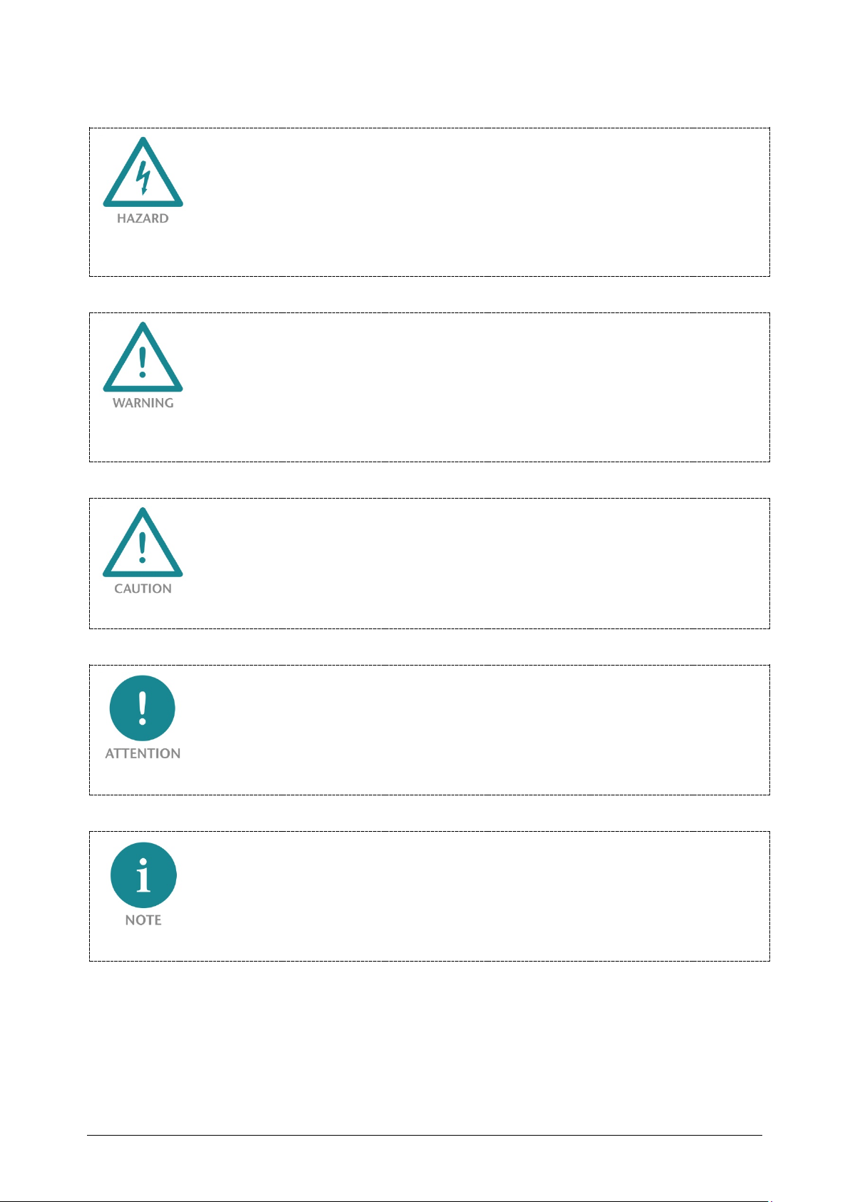
If the hazard warning is ignored, there is an imminent danger to life and health of people from
electrical voltage.
If the hazard warning is ignored, there is a probable danger to life and health of people from
electrical voltage.
If the hazard warning is ignored, people can be injured or harmed.
Draws attention to sources of error that can damage equipment or the environment.
Gives an indication for better understanding or preventing errors.
TB20 – Serial interface 1SI | Version 1| 13.03.2019 8
Page 9
1.4 Intended use
The TB20 I/O system is an open-ended, modular, and distributed peripheral system
designed to be mounted on 35 mm DIN rails.
Communication with a higher-level control system is via a bus system / network and a
TB20 bus coupler. Up to 64 modules from the TB20 range can be set up on a bus coupler.
The bus couplers support hot-swapping for replacing modules during ongoing operation.
All components are supplied with a factory hardware and software configuration. The user
must carry out the hardware and software configuration for the conditions of use.
Modifications to hardware or software configurations which are beyond the documented
options are not permitted and nullify the liability of Systeme Helmholz GmbH.
The TB20 devices should not be used as the only means for preventing hazardous situations
on machinery and equipment.
Successful and safe operation of the TB20 devices requires proper transport, storage,
installation, assembly, installation, commissioning, operation, and maintenance.
The ambient conditions provided in the technical specifications must be adhered to.
The TB20 systems have protection rating of IP20 and must have a control box/cabinet
fitted to protect against environmental influences in an electrical operating room. To
prevent unauthorized access, the doors of control boxes/cabinets must be closed and
possibly locked during operation.
TB20 devices can be equipped with modules that can carry dangerously high voltages. The
voltages connected to the TB20 devices can result in hazards during work on the TB20 devices.
1.5 Improper use
The consequences of improper use may include personal injuries of the user or third parties as
well as property damage to the control system, the product, or environment. Use TB20 devices
only as intended!
TB20 – Serial interface 1SI | Version 1| 13.03.2019 9
Page 10
1.6 Installation
1.6.1 Access restriction
The modules are open operating equipment and must only be installed in electrical
equipment rooms, cabinets, or housings.
Access to the electrical equipment rooms, cabinets, or housings must only be possible using
a tool or key, and access should only be granted to trained or authorized personnel.
1.6.2 Electrical installation
Observe the regional safety regulations.
TB20 devices can be equipped with modules that can carry dangerously high voltages. The
voltages connected to the TB20 devices can result in hazards during work on the TB20 devices.
1.6.3 Protection against electrostatic discharges
To prevent damage through electrostatic discharges, the following safety measures are to be
followed during assembly and service work:
• Never place components and modules directly on plastic items (such as polystyrene,
PE film) or in their vicinity.
• Before starting work, touch the grounded housing to discharge static electricity.
• Only work with discharged tools.
• Do not touch components and assemblies on contacts.
1.6.4 Overcurrent protection
To protect the TB20 and the supply line, a slow-blowing 8 A line protection fuse is
required.
1.6.5 EMC protection
To ensure electromagnetic compatibility (EMC) in your control cabinets in electrically
harsh environments, the known rules of EMC-compliant configuration are to be observed
in the design and construction.
TB20 – Serial interface 1SI | Version 1| 13.03.2019 10
Page 11

1.6.6 Operation
Operate the TB20 only in flawless condition. The permissible operating conditions and
performance limits must be adhered to.
Retrofits, changes, or modifications to the device are strictly forbidden.
The TB20 is an operating means intended for use in industrial plants. During operation, the
TB20 can carry dangerous voltages. During operation, all covers on the unit and the
installation must be closed in order to ensure protection against contact.
1.6.7 Liability
The contents of this manual are subject to technical changes resulting from the continuous
development of products of Systeme Helmholz GmbH. In the event that this manual
contains technical or clerical errors, we reserve the right to make changes at any time
without notice. No claims for modification of delivered products can be asserted based on
the information, illustrations, and descriptions in this documentation. Beyond the
instructions contained in the operating manual, the applicable national and international
standards and regulations also must be observed in any case.
1.6.8 Disclaimer of liability
Systeme Helmholz GmbH is not liable for damages if these were caused by use or
application of products that was improper or not as intended.
Systeme Helmholz GmbH assumes no responsibility for any printing errors or other
inaccuracies that may appear in the operating manual, unless there are serious errors about
which Systeme Helmholz GmbH was already demonstrably aware.
Beyond the instructions contained in the operating manual, the applicable national and
international standards and regulations also must be observed in any case.
Systeme Helmholz GmbH is not liable for damage caused by software that is running on
the user’s equipment which compromises, damages, or infects additional equipment or
processes through the remote maintenance connection and which triggers or permits
unwanted data transfer.
1.6.9 Warranty
Report any defects to the manufacturer immediately after discovery of the defect.
The warranty is not valid in case of:
• Failure to observe these operating instructions
• Use of the device that is not as intended
• Improper work on and with the device
• Operating errors
• Unauthorized modifications to the device
The agreements met upon contract conclusion under “General Terms and Conditions of
Systeme Helmholz GmbH” apply.
TB20 – Serial interface 1SI | Version 1| 13.03.2019 11
Page 12
2 System overview
2.1 General Information
The TB20 I/O system is an open, modular, and distributed peripheral system designed to be
mounted on 35-mm DIN rails.
It is made up of the following components:
• Bus couplers
• Peripheral modules
• Power and isolation modules
• Power modules
By using these components, you can build a custom automation system that is tailored to
your specific needs and that can have up to 64 modules connected in series to a bus
coupler. All components have a protection rating of IP20.
2.2 The components that make up the TB20 I/O system
2.2.1 Bus coupler
The system’s bus coupler includes a bus interface and a power module. The bus interface is
responsible for establishing a connection to the higher-level bus system and is used to
exchange I/O signals with the automation system’s CPU.
The power module is responsible for powering the coupler’s electronics and all connected
peripheral modules.
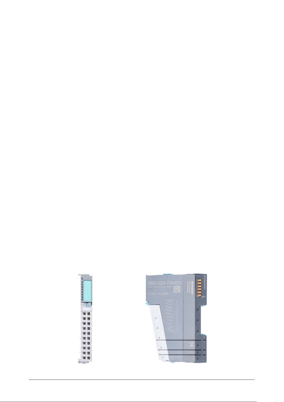
2.2.2 Peripheral modules
The system’s peripheral modules are electronic components to which peripheral devices
such as sensors and actuators can be connected. A variety of peripheral modules with
different tasks and functions are available.
Example: Peripheral module with 10-pin front connector
TB20 – Serial interface 1SI | Version 1| 13.03.2019 12
Page 13
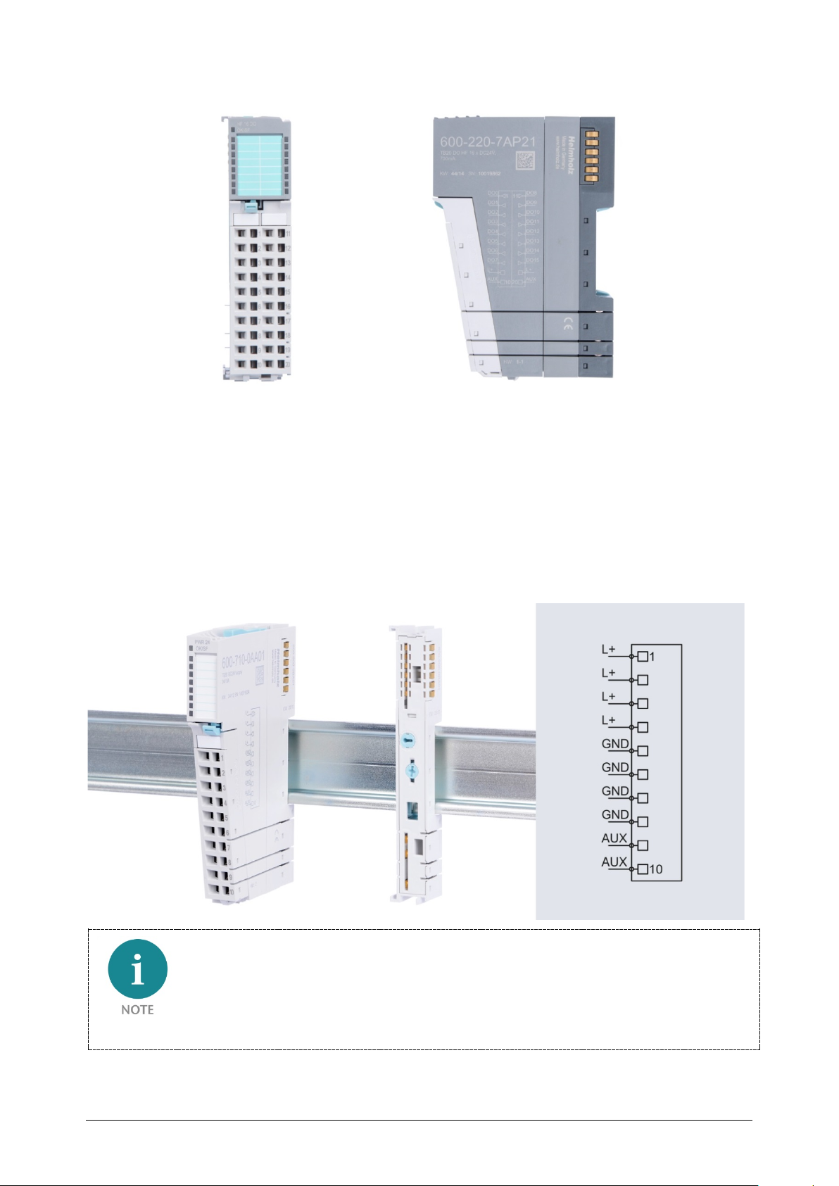
Example: Peripheral module with 20-pin front connector
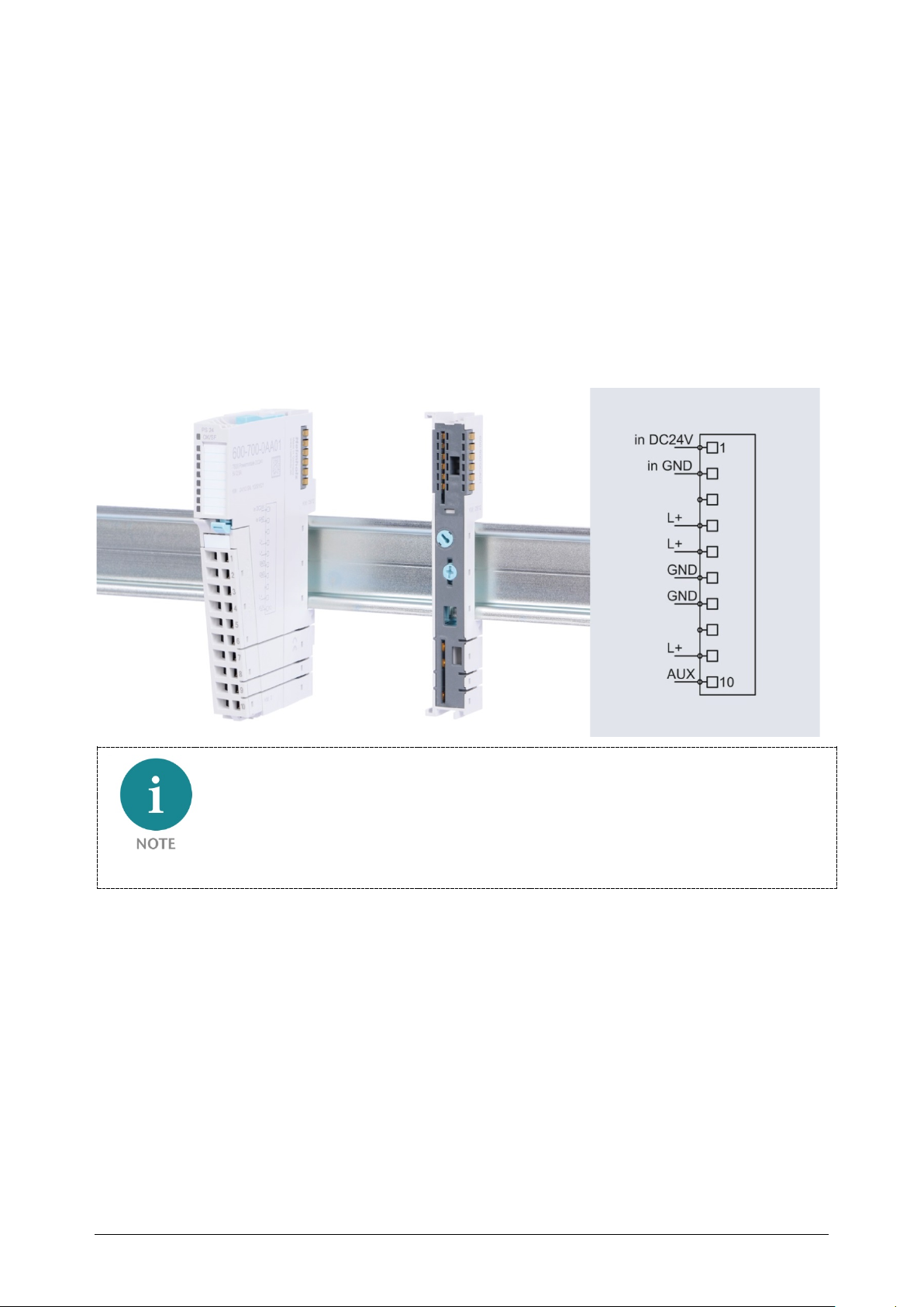
2.2.3 Power and isolation module
The system’s bus coupler provides the supply voltage for the communications bus (5 V,
top) and for external signals (24 V, bottom). These voltages are passed from module to
module through the base modules.
Power and isolation modules make it possible to segment the power supply for external
signals into individual power supply sections that are powered separately. Meanwhile, the
communications bus signals and supply voltage simply continue to be passed through, in
contrast to the way they are handled by power modules (see section 2.2.4).
Power and insulation modules have a lighter body color.
TB20 – Serial interface 1SI | Version 1| 13.03.2019 13
Page 14
2.2.4 Power module
The system’s bus coupler provides the supply voltage for the communications bus (5 V,
top) and for external signals (24 V, bottom). These voltages are passed from module to
module through the base modules.
Power modules make it possible to segment the power supply for both external signals and
the communication bus into individual power supply sections that are powered separately.
Power modules deliver all necessary power to the peripheral modules connected after them
and, if applicable, all the way to the next power module or power and isolation module. A
power module is required whenever the power supplied by the coupler alone is not
sufficient, e.g., when there are a large number of modules with high power requirements.
The “TB20 ToolBox” configuration program can be used to determine whether power
modules are needed, as well as how many of them will be needed.
Power modules have a lighter body color.
TB20 – Serial interface 1SI | Version 1| 13.03.2019 14
Page 15
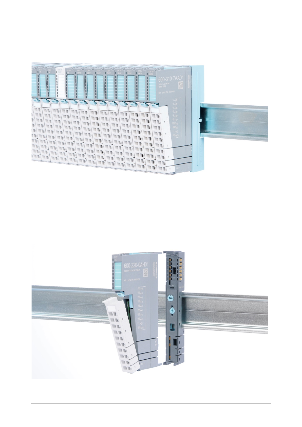
2.2.5 Final bus cover
The final bus cover protects the contacts on the last base module from accidental contact
by covering the outer right-hand side of the base module.
2.2.6 Components in a module
Each module consists of three parts:
• Base module
• Electronic module
• Front connectors
TB20 – Serial interface 1SI | Version 1| 13.03.2019 15
Page 16
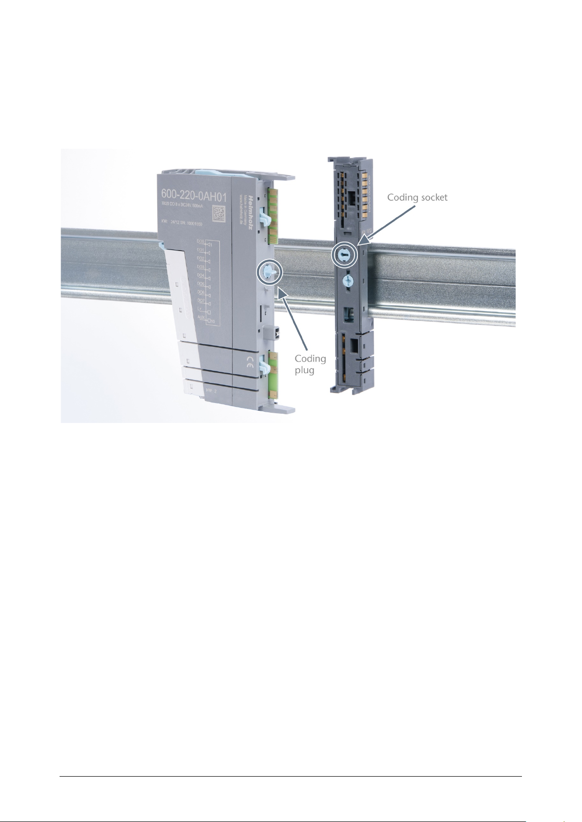
2.2.7 Module Coding
Electronic modules and base modules feature coding elements meant to prevent the wrong
spare electronic modules from being plugged in during maintenance and repairs.
These coding elements consist of a coding plug on the electronic module and a coding
socket on the base module (see following figure).
The coding plug and coding socket can each be in one of eight different positions. Each of
these eight positions is factory-assigned to a specific type of module (Digital In, Digital Out,
Analog In, Analog Out, Power) from the TB20 system. It will only be possible to plug an
electronic module into a base module if the position of the coding plug and the position of
the coding socket match. If the positions differ, the electronic module is mechanically
blocked.
TB20 – Serial interface 1SI | Version 1| 13.03.2019 16
Page 17
3 Installation and removal
TB20 modules can carry lethal voltage.
Before starting any work on TB20 system components, make sure to de-energize all
components, as well as the cables supplying them with power! During work when the system
is live, there is the risk of fatal electrocution!
Insulation must be carried out according to VDE 0100/IEC 364 and performed in accordance
with applicable national standards. The TB20 IO system has protection rating IP20. If a higher
protection rating is required, the system must be installed in a housing or control cabinet. In
order to ensure safe operation, the ambient temperature must not exceed 60 °C.
3.1 Installation position
The TB20 I/O system can be installed in any position.
In order to achieve optimum ventilation and be able to use the system at the specified
maximum ambient temperature, it will, however, be necessary to use a horizontal
installation layout.
3.2 Minimum clearance
It is recommended to adhere to the minimum clearances specified when installing the
coupler and modules. Adhering to these minimum clearances will ensure that:
• The modules can be installed and removed without having to remove any other
system components
• There will be enough space to make connections to all existing terminals and contacts
using standard accessories
• There will be enough space for cable management systems (if needed)
The minimum clearances for mounting TB20 components are: 30 mm on the top and on
bottom and 10 mm on each side.
TB20 – Serial interface 1SI | Version 1| 13.03.2019 17
Page 18
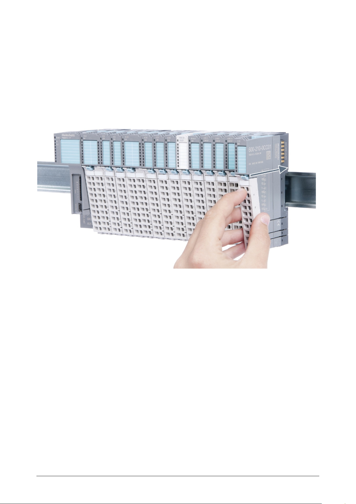
3.3 Installing and removing peripheral modules
3.3.1 Installation
Installing an assembled peripheral module
Place the assembled module on the DIN rail by moving it straight towards the rail. Make
sure that the module engages the upper and lower guide elements of the previous module.
Then push the upper part of the module towards the DIN rail until the rail fastener fastens
into place on the inside snaps with a soft click.
Installing the individual parts of a peripheral module one after the other
Place the base module on the DIN rail from below in an inclined position. Then push the
upper part of the base module towards the rail until the module is parallel to the rail and
the rail fastener on the inside snaps into place with a soft click.
Place an electronic module with matching coding (see the “Module Coding” section on
page 16) on the base module in a straight line from above and then gently push it into the
base module until both modules are fully resting against each other and the module
fastener snaps into place with a soft click.
Finally, place the front connector on the electronic module from below in an inclined
position and then gently push it onto the electronic module until the front connector
fastener snaps into place with a soft click.
TB20 – Serial interface 1SI | Version 1| 13.03.2019 18
Page 19
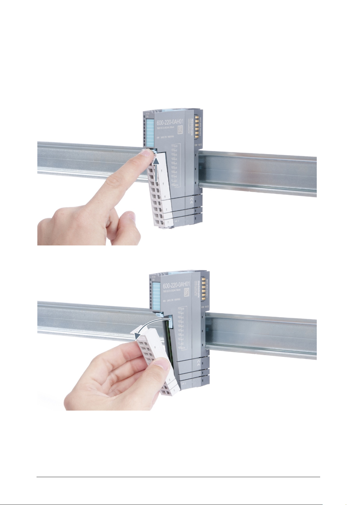
3.3.2 Removal
To remove a peripheral module, follow the four steps below:
Step 1: Remove the front connector
To remove the front connector, push the tab above the front connector upwards (see the
picture below). This will push out the front connector, after which you can pull it out.
TB20 – Serial interface 1SI | Version 1| 13.03.2019 19
Page 20
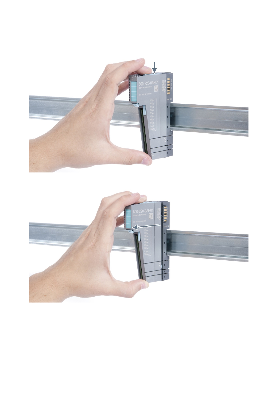
Step 2: Remove the electronic module
To remove the electronic module, use your middle finger to push on the lever from above
and then use your thumb and index finger to pull out the electronic module while holding
the lever down (see the picture below).
TB20 – Serial interface 1SI | Version 1| 13.03.2019 20
Page 21
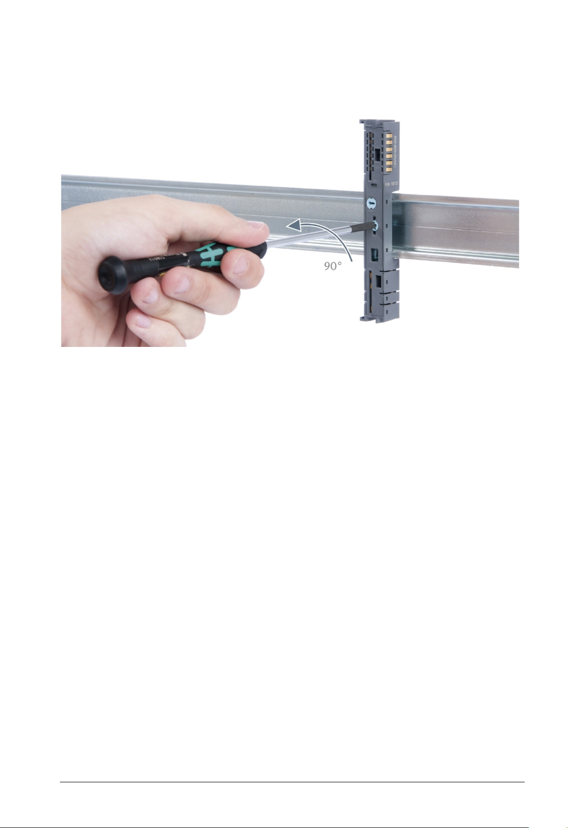
Step 3: Release the base module
Use a screwdriver to release the base module. by turning the locking mechanism 90°
counterclockwise.
Step 4: Remove the base module
Remove the base module by pulling it towards you.
TB20 – Serial interface 1SI | Version 1| 13.03.2019 21
Page 22
3.4 Replacing an electronic module
The procedure for replacing the electronic module on a peripheral module consists of four
steps.
If you need to replace the electronic module while the system is running, make sure to take
into account the general technical specifications for the bus coupler being used.
TB20 modules can carry lethal voltage.
Before starting any work on TB20 system components, make sure to de-energize all
components, as well as the cables supplying them with power! During work when the system
is live, there is the risk of fatal electrocution!
Note the wiring diagram of the system and switch off dangerous voltages before starting work!
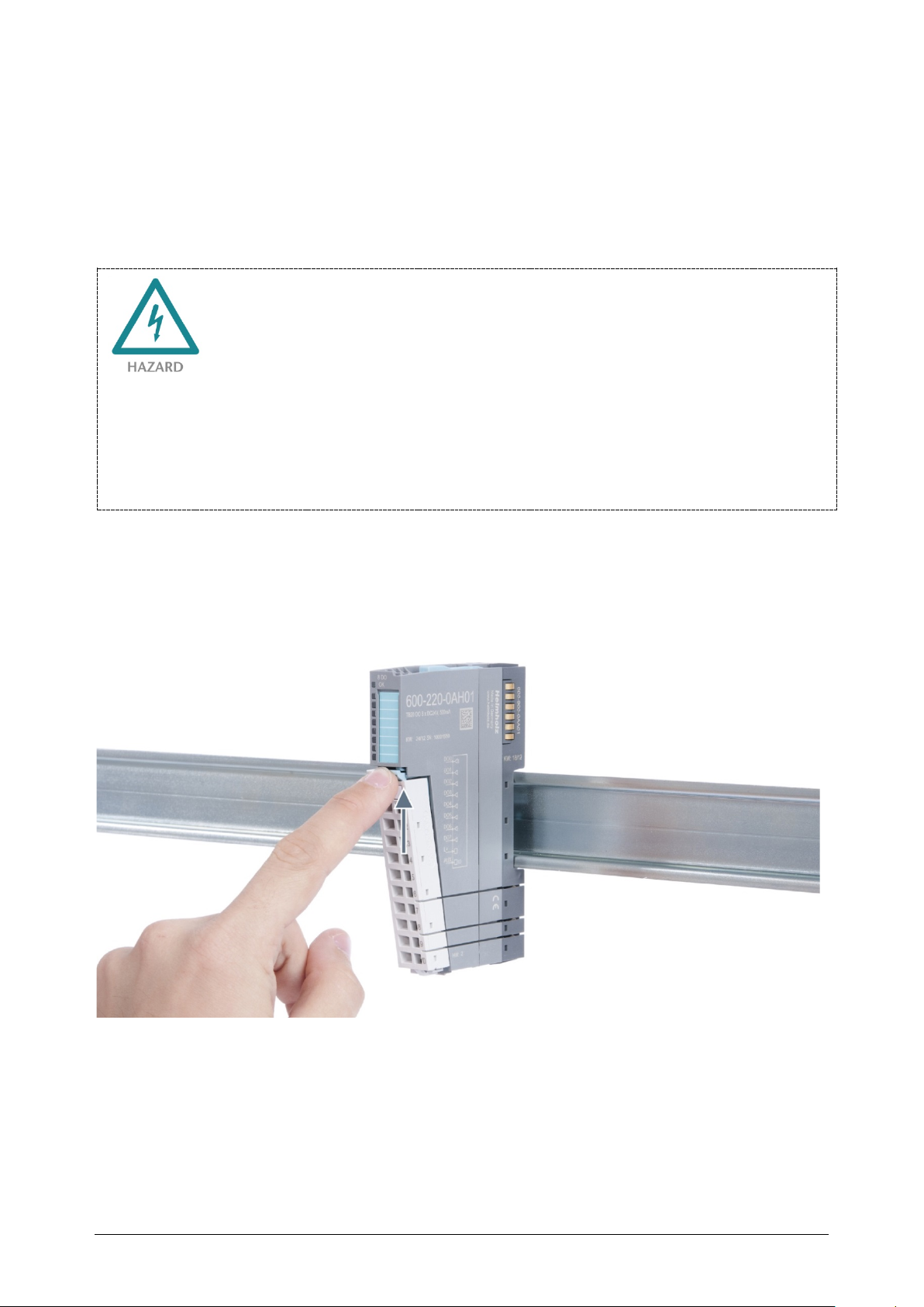
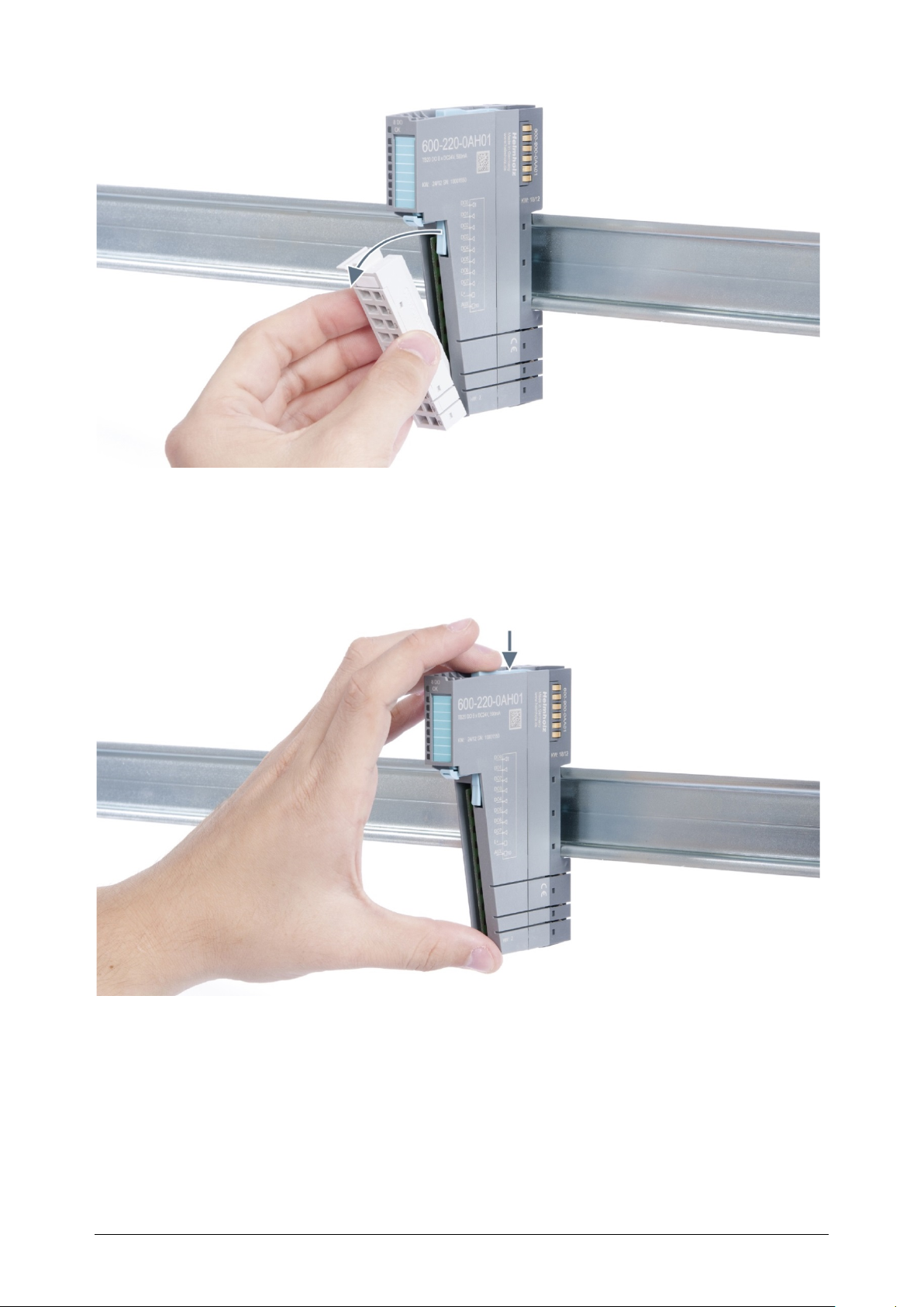
Step 1: Remove the front connector
To remove the front connector, push the tab above the front connector upwards (see the
picture below). This will push out the front connector, after which you can pull it out.
TB20 – Serial interface 1SI | Version 1| 13.03.2019 22
Page 23
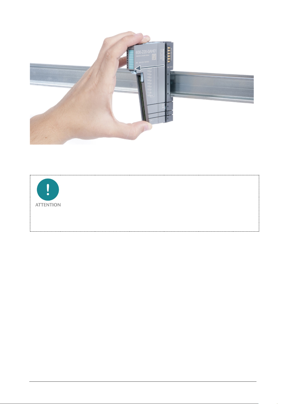
Step 2: Remove the electronic module
To remove the electronic module, use your middle finger to push on the lever from above
and then use your thumb and index finger to pull out the electronic module while holding
the lever down (see the picture below).
TB20 – Serial interface 1SI | Version 1| 13.03.2019 23
Page 24
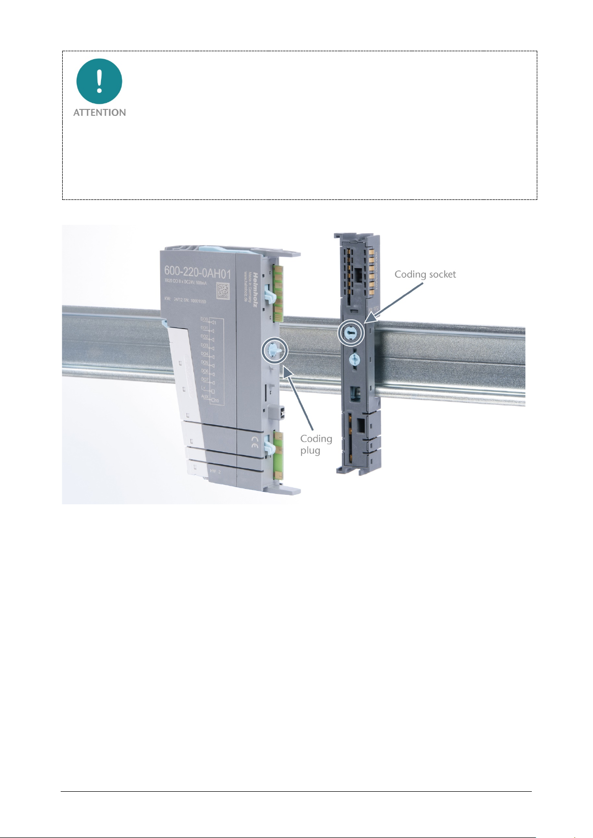
Step 3: Plug in a new electronic module
The electronic module must be snapped into place on the base module with a single
continuous movement. If the electronic module is not snapped into place firmly and straight
on the base module, bus malfunctions may occur.
TB20 – Serial interface 1SI | Version 1| 13.03.2019 24
Page 25
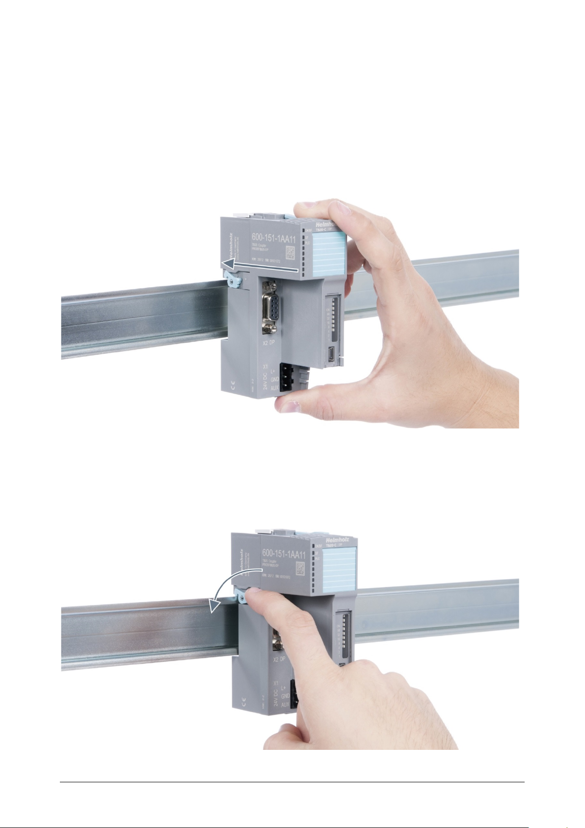
If the electronic module cannot be plugged into the base module, check whether the coding
elements on the electronic module and base module (see figure below) match. If the coding
elements on the electronic module do not match those on the base module, you may be
attempting to plug in the wrong electronic module.
For more information on coding elements, please consult section 2.2.7.
Step 4: Plug in the front connector
TB20 – Serial interface 1SI | Version 1| 13.03.2019 25
Page 26
3.5 Installing and removing the coupler
3.5.1 Installation
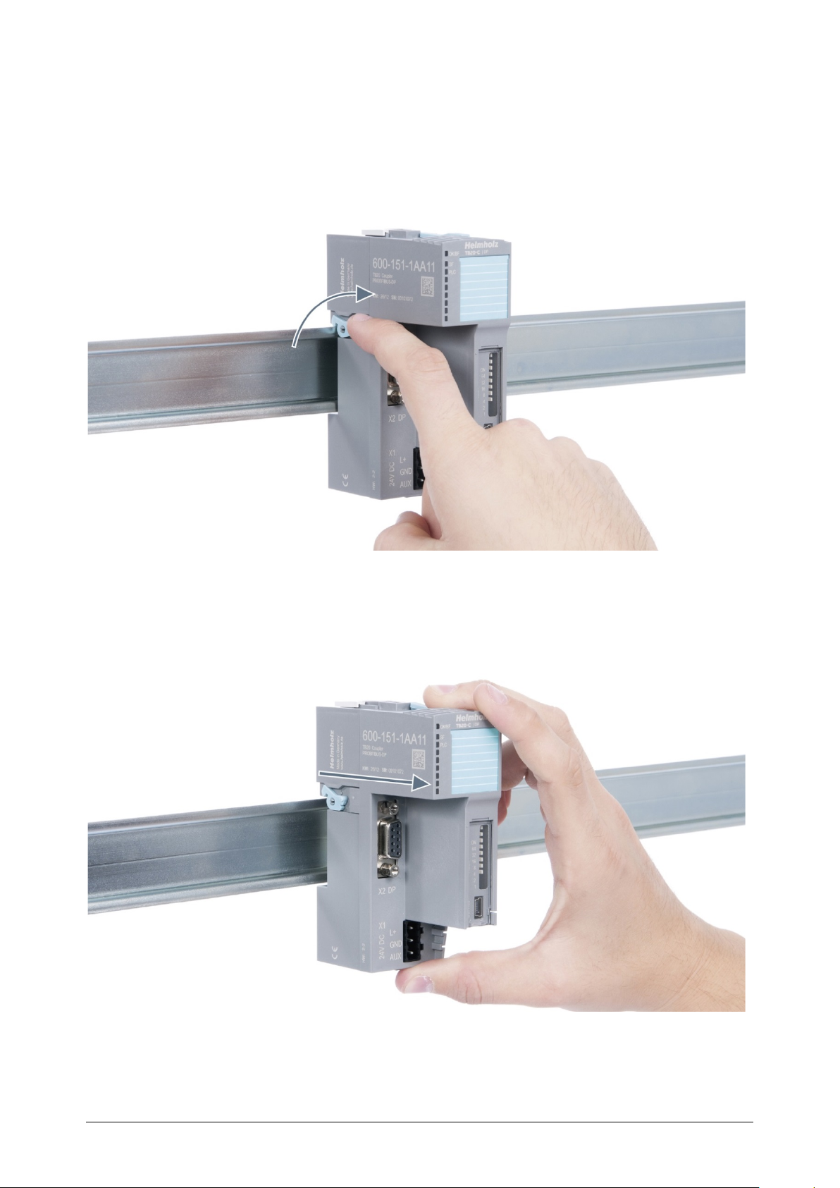
Step 1: Place the coupler on the DIN rail
Place the coupler, together with the attached base module, on the DIN rail by moving it
straight towards the rail. Then push the coupler towards the rail until the base module’s
rail fastener snaps into place with a soft click.
Step 2: Secure the coupler on the DIN rail
Use the locking lever on the left side of the coupler to lock the coupler into position on the
DIN rail.
TB20 – Serial interface 1SI | Version 1| 13.03.2019 26
Page 27
3.5.2 Removal
Step 1: Release the locking mechanism
Release the locking lever on the left side of the coupler in order to disengage it from the
DIN rail.
Step 2: Remove the coupler
Use your middle finger to push on the lever from above and use your thumb and index
finger to pull out the coupler while holding the lever down.
TB20 – Serial interface 1SI | Version 1| 13.03.2019 27
Page 28
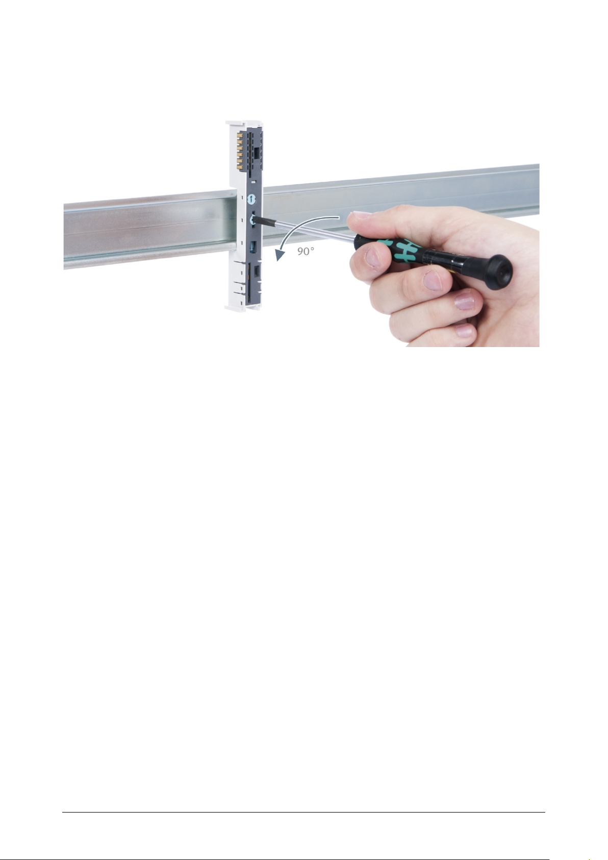
Step 3: Release the base module
Use a screwdriver to release the base module.
Step 4: Remove the base module
Remove the base module by pulling it towards you.
TB20 – Serial interface 1SI | Version 1| 13.03.2019 28
Page 29
3.6 Installing and removing the final bus cover
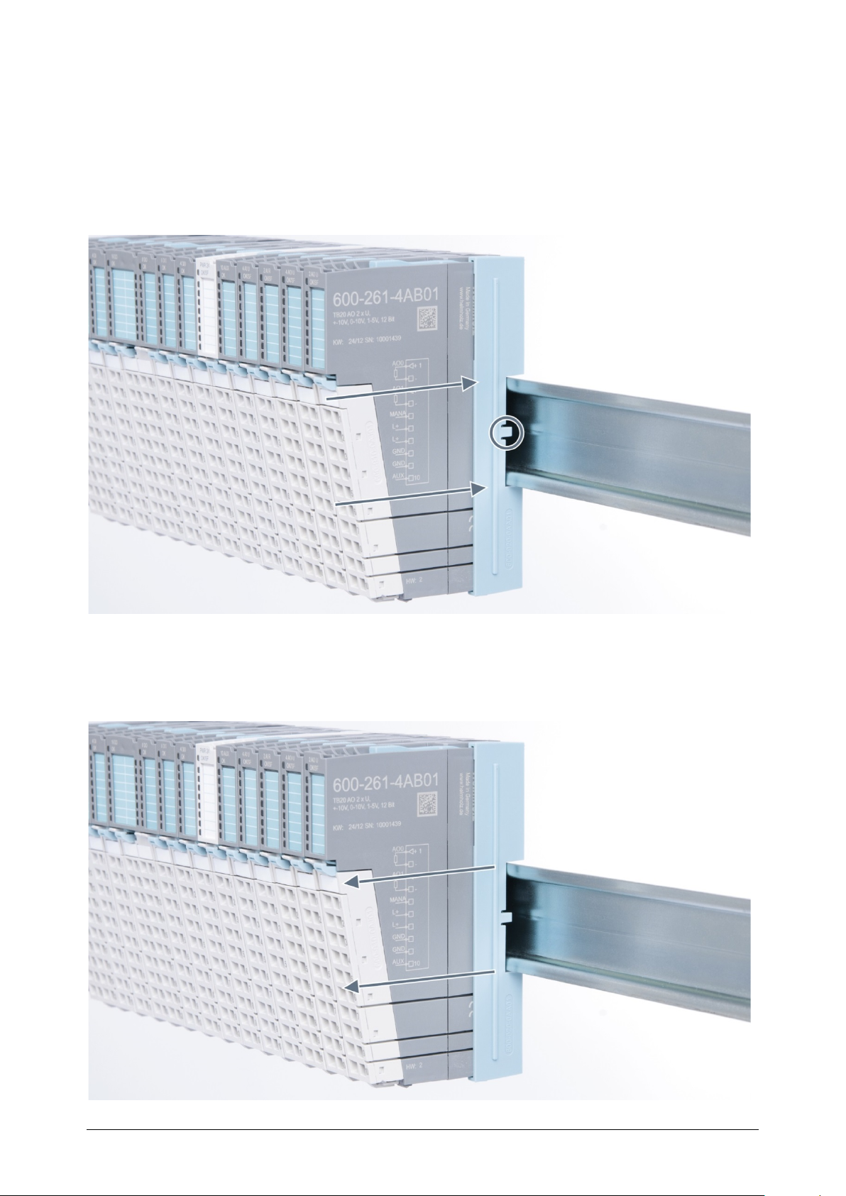
3.6.1 Installation
Slide the final bus cover onto the last module along the case, starting from the end with
the front connector and moving towards the DIN rail, until the cover covers the base
module’s contacts and the tab snaps into place.
3.6.2 Removal
Pull the final bus cover along the module’s case and away from the DIN rail in order to
remove it from the module.
TB20 – Serial interface 1SI | Version 1| 13.03.2019 29
Page 30
4 Configuration/wiring
4.1 EMC/safety/shielding
The TB20 IO system complies with EU Directive 2004/108/EC (“Electromagnetic
Compatibility”).
One effective way to protect against disturbances caused by electromagnetic interference is
to shield electric cables, wires, and components.
When putting together the system and routing of the required cables, make sure to fully
comply with all standards, regulations, and rules regarding shielding (please consult the
relevant guidelines and documents published by the PROFIBUS User Organization as well). All
work must be done professionally!
Shielding faults can result in serious malfunctions, including the system’s failure.
To ensure electromagnetic compatibility (EMC) in your control cabinets in electrically
harsh environments, the following EMC rules are to be observed in the design:
• All metal parts of the cabinet are to be connected with each other over a large area
with good conductivity (no paint on paint). Where necessary, use contact washers or
serrated washers.
• The cabinet door must be connected to the ground straps (top, middle, bottom) over as
short a distance as possible.
• Signal cables and power cables are to be laid separated spatially by a minimum
distance of 20 cm from each in order to avoid coupling paths.
• Run signal lines only from one level into the cabinet if possible.
• Unshielded cables in the same circuit (outgoing and incoming conductors) must be
twisted if possible.
• Contactors, relays, and solenoid valves in the closet, or in adjacent cabinets if
applicable, must be provided with quenching combinations; e.g., with RC elements,
varistors, diodes.
• Do not lay wires freely in the closet; instead, run them as closely as possible to the
cabinet housing or mounting panels. This also applies to reserve cables. These must be
grounded on at least one end, and it is better if they are grounded on both ends
(additional shielding effect).
• Unnecessary line lengths should be avoided. Coupling capacitances and inductances
are kept low in this way.
• Analog signal lines and data lines must be shielded.
TB20 – Serial interface 1SI | Version 1| 13.03.2019 30
Page 31
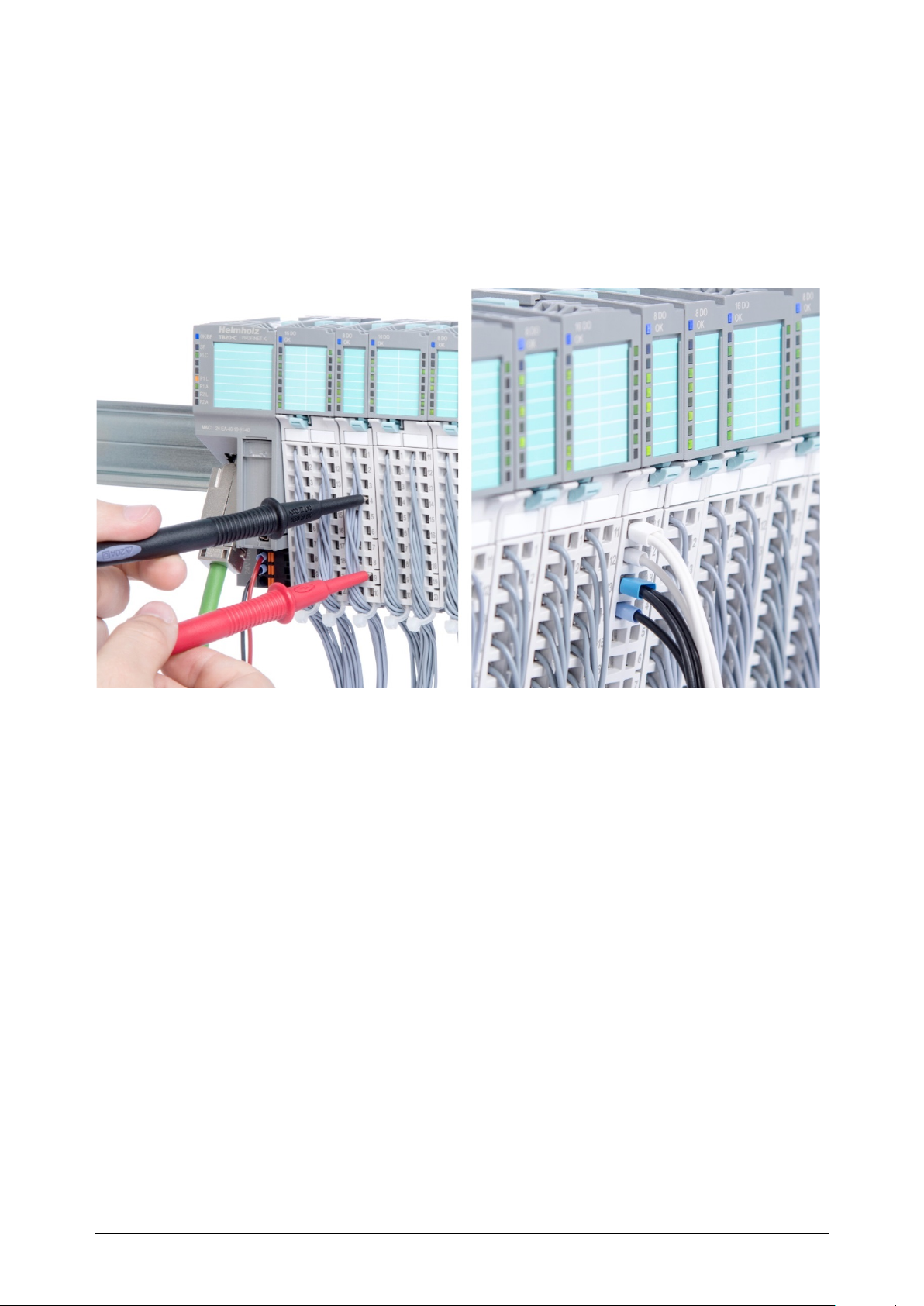
4.2 Front connectors
The front connector’s spring-clamp terminals are designed for a cross-sectional cable area of
up to 1.5 mm² (16–22 AWG) with or without ferrules.
It is also possible, for example, to connect two 0.75 mm² wires to a single spring-type
terminal, provided the maximum cross-sectional cable area of 1.5 mm² per terminal is not
exceeded.
The cables can be attached to the underside of the front connector with a cable tie.
TB20 – Serial interface 1SI | Version 1| 13.03.2019 31
Page 32
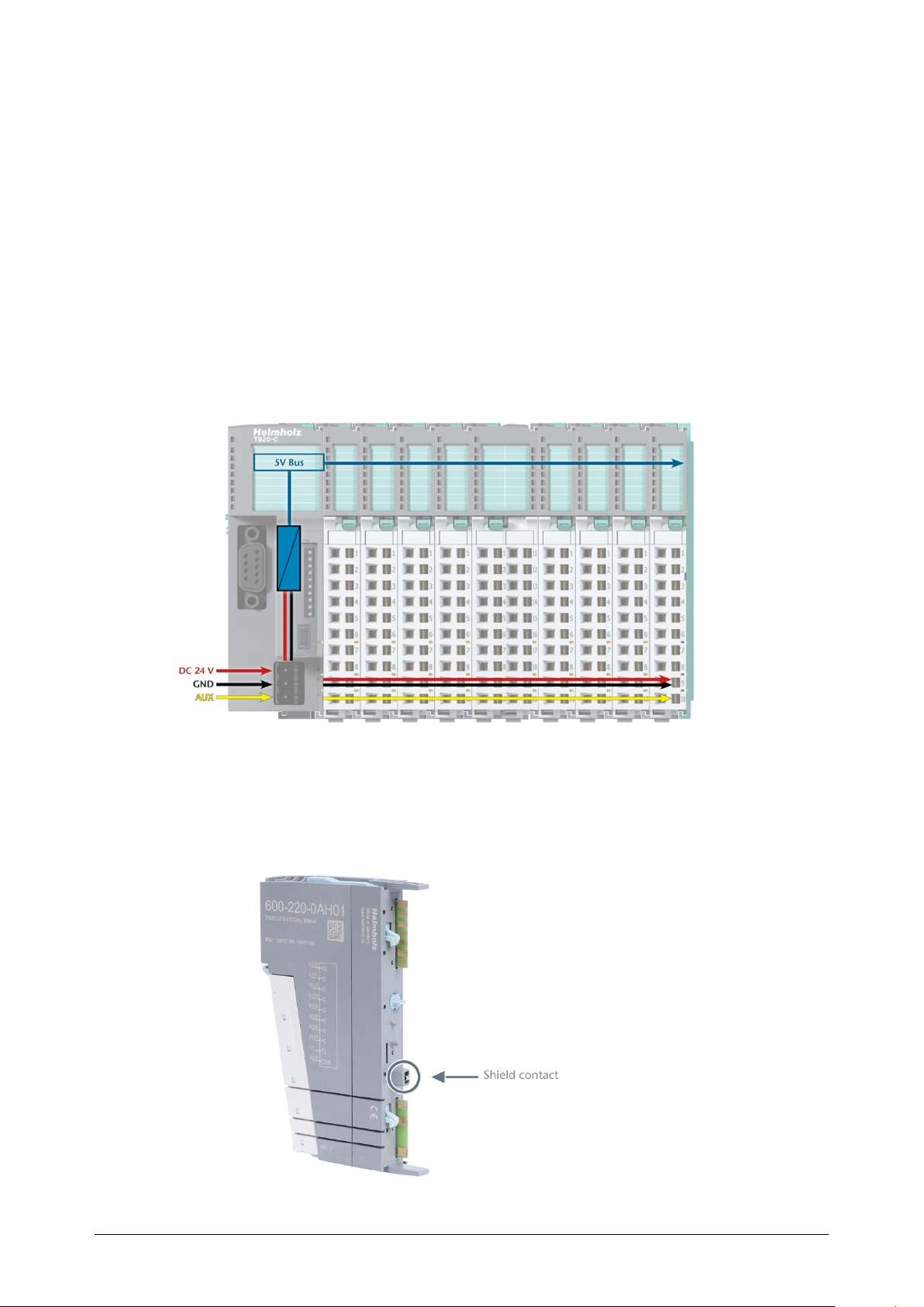
4.3 Wiring the coupler
A power supply unit is integrated into the bus coupler. The power supply unit is
responsible for powering the peripheral modules connected to the coupler.
In turn, it draws its own power from the three-pin connector on the front (24 VDC, GND,
AUX).
The 24 V connector is used to power two buses:
• The power bus used to power the I/O components (24 VDC, GND, AUX)
• The communications bus used to power the electronics in the peripheral modules
The AUX pin can be used to connect and use an additional voltage potential. Every
peripheral module has an AUX terminal on its front connector (the bottommost terminal,
i.e., terminals 10 and 20).
The coupler and the modules are grounded via the shield contact to the DIN rail. The DIN
rail must be grounded. The surface of the DIN rail must be clean and conduct electricity
well.
TB20 – Serial interface 1SI | Version 1| 13.03.2019 32
Page 33
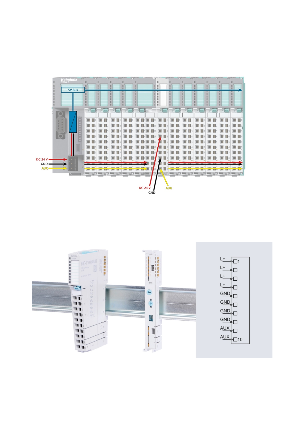
4.4 Using power and isolation modules
Power and isolation modules make it possible to segment the power supply for external
signals (24 V, GND, AUX) into individual power supply sections that are powered
separately.
The order no. for the power and isolation module for 24 V signals is 600-710-0AA01.
Its electronic module and base module have the same light gray color as the front
connector, ensuring that all power and isolation modules will stand out visually in the
system and make it easy to clearly distinguish each individual power supply segment.
TB20 – Serial interface 1SI | Version 1| 13.03.2019 33
Page 34
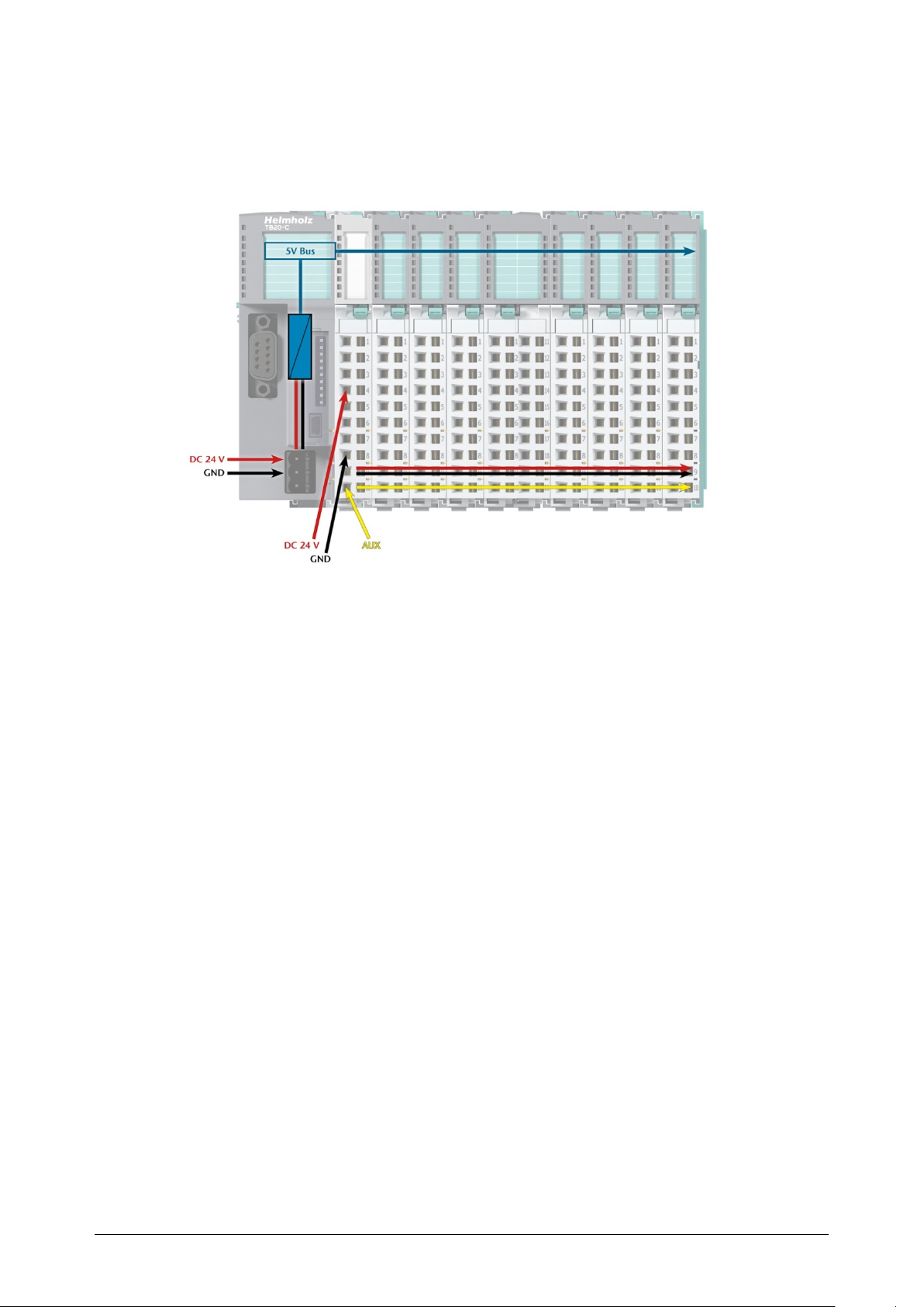
4.5 Separate power supply segments for the coupler and the I/O components
If the power supply for the coupler needs to be separate from the power supply for the I/O
modules, a power and isolation module can be used right after the coupler.
TB20 – Serial interface 1SI | Version 1| 13.03.2019 34
Page 35
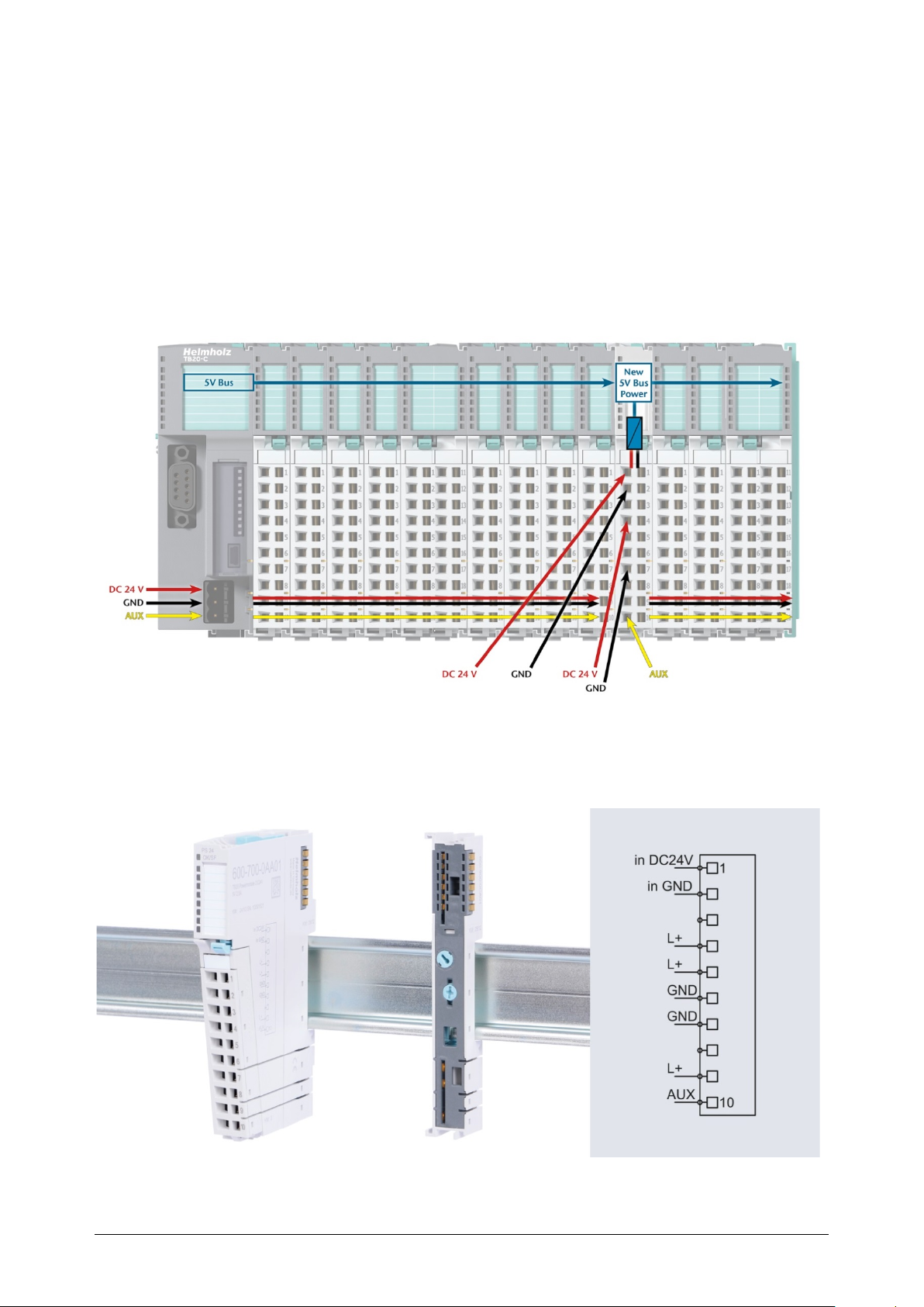
4.6 Using Power Modules
Power modules deliver all necessary power to the connected peripheral modules and, if
applicable, all the way to the next power module or power and isolation module. Power
modules must be used whenever the power supplied by the coupler alone is not sufficient,
that is, when there are a large number of modules on the bus. The “TB20 ToolBox”
parameter configuration and diagnosis program can be used to calculate a system’s total
current draw.
24 VDC, GND, and AUX are fed into the terminals on the front, while the connected
modules are powered through the base modules’ bus system.
The order no. for the power module is 600-700-0AA01. The electronic module of the power
module is light gray like the front connector. The base module of the power module is light
gray with a dark top part.
TB20 – Serial interface 1SI | Version 1| 13.03.2019 35
Page 36
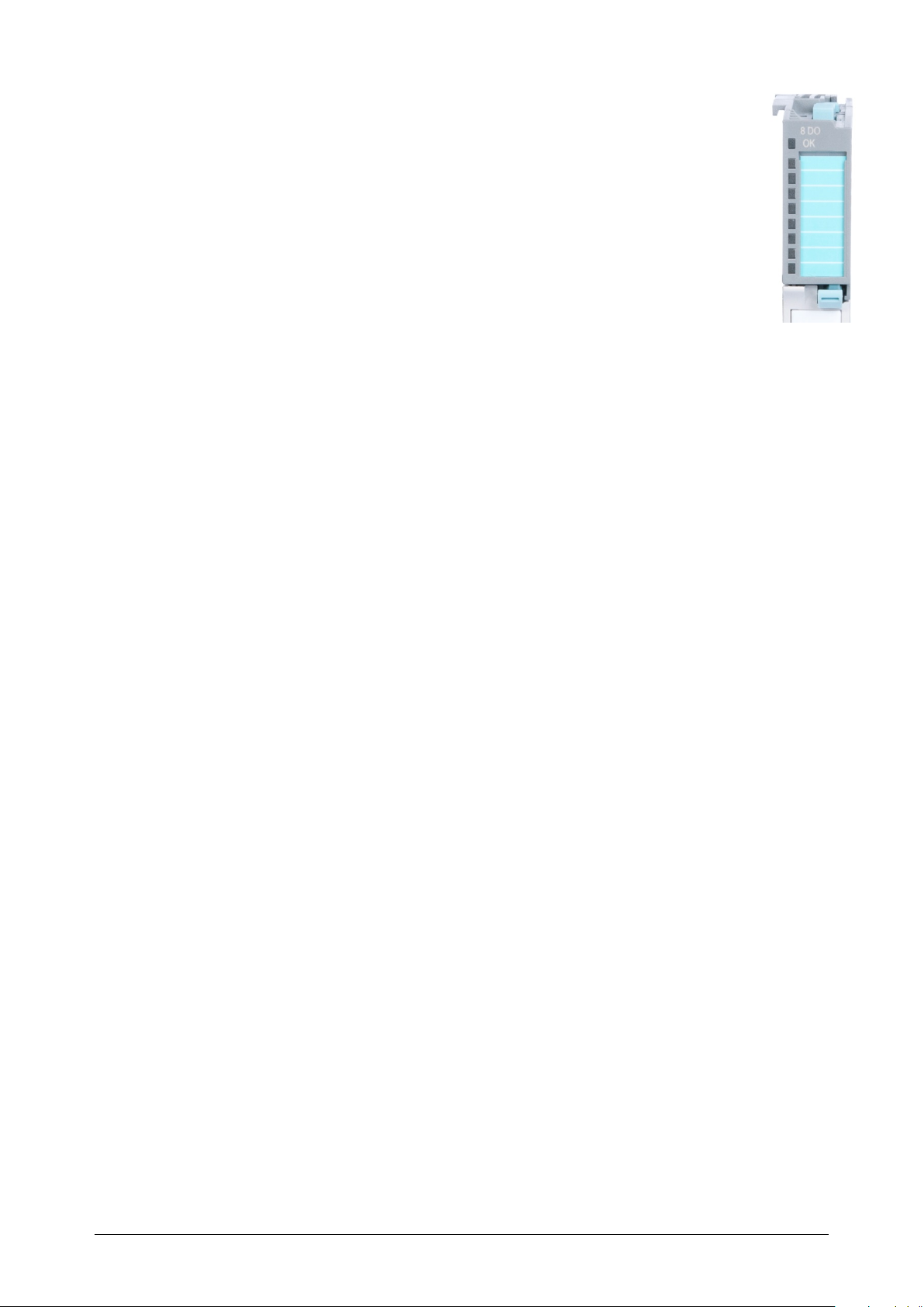
4.7 Function of the OK-LED
The topmost LED (OK-LED) on every module indicates the module’s current
system status.
Solid blue light: The module is running (RUN)
Slowly flashing blue light: The module is stopped (STOP); substitute values (if
any) are being applied
Quickly flashing blue light: The module is idle (IDLE); its parameters have not
been configured yet
Solid red light: The module is indicating a diagnostic error
Flashing red light: The module is indicating a parameter assignment error
The red LED lights will only be shown on modules with configurable parameters or
diagnosis capabilities.
4.8 Electronic nameplate
All of a TB20 module’s important information can be found on its electronic nameplate.
This information includes, for example, the corresponding module ID, module type, order
number, unique serial number, hardware version, firmware version, and internal range of
functionalities.
This information can be read in a number of ways, one of which is using the “TB20
ToolBox” configuration and diagnosis program. The modules’ electronic nameplates not
only make it possible to prevent configuration errors (setup), but also make maintenance
(servicing) easier.
4.9 Fusing
The TB20 coupler’s and power modules’ power supply must be externally fused with a
slow-blowing fuse, maximum 8 A, appropriate for the required maximum current.
TB20 – Serial interface 1SI | Version 1| 13.03.2019 36
Page 37
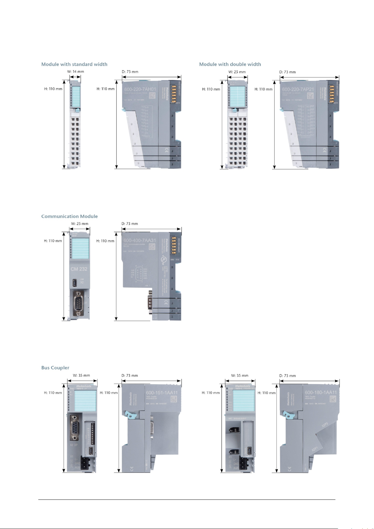
4.10 Dimensions
TB20 – Serial interface 1SI | Version 1| 13.03.2019 37
Page 38

5 TB20 – Serial interface 1SI
5.1 Properties RS232
The 1SI serial interface is a module for the Helmholz fieldbus I/O system TB20.
Communication with a Helmholz fieldbus coupler is via the backplane bus of the TB20
system.
The 1SI serial interface is a voltage interface for serial data transmission in accordance with
the RS232C standard.
Through the TB20 bus, parameter data and control commands are transmitted from the
TB20 fieldbus coupler to the 1SI serial interface. The 1SI serial interface sends feedback data
to the TB20 fieldbus coupler.
The 1SI serial interface allows for a point-to-point connection with various modules with
serial interface.
Serial communication
The 1SI serial interface handles the data transmission with the communication partner
automatically. The ASCII and the 3964(R) protocols are available for bidirectional data
transfer. The modes half duplex and full duplex are possible.
Half-duplex
The data is transmitted alternately between the communication partners. A
communication partner cannot transmit and receive simultaneously. Control characters for
flow control are transmitted regardless of the transmit/receive operation.
Full-duplex
The data is transmitted simultaneously in both directions between the communication
partners. The communication partners must be equipped for simultaneous transmit/receive
operation.
The 1SI serial interface can be configured via the TB20-ToolBox software and GSD, and
GSDML.
TB20 – Serial interface 1SI | Version 1| 13.03.2019 38
Page 39

5.2 Properties RS422/RS485
The 1SI serial interface is a module for the Helmholz fieldbus I/O system TB20.
Communication with a Helmholz fieldbus coupler is via the backplane bus of the TB20
system.
The 1SI serial interface is a voltage difference interface for serial data transmission in
accordance with the RS422/485 standard.
Through the TB20 bus, parameter data and control commands are transmitted from the
TB20 fieldbus coupler to the 1SI serial interface. The 1SI serial interface sends feedback data
to the TB20 fieldbus coupler.
The 1SI serial interface allows for a point-to-point connection with various modules with
serial interface. The ASCII and the 3964(R) protocols are supported (3964(R) not for RS485)
for communication with connected serial devices.
Serial communication
The 1SI serial interface handles the data transmission with the communication partner
automatically. The ASCII and the 3964(R) protocols are available (3964(R) not for RS485)
for bidirectional data transfer. The modes half duplex and full duplex (except 3964(R)) are
possible.
Half-duplex RS422/RS485
The data is transmitted alternately between the communication partners. A
communication partner cannot transmit and receive simultaneously. Control characters for
flow control are transmitted regardless of the transmit/receive operation.
Full-duplex RS422
The data is transmitted simultaneously in both directions between the communication
partners. The communication partners must be equipped for simultaneous transmit/receive
operation.
The 1SI serial interface can be configured via the TB20-ToolBox software and GSD, and
GSDML.
TB20 – Serial interface 1SI | Version 1| 13.03.2019 39
Page 40

5.2.1 Functions in the RS232 operating mode
Communications module 1SI serial interface 600-400-7BA31
Protocols ASCII 3964(R)
Physical layer RS232
Connection Sub-D 9-pin
Transmission rates
Procedure ASCII driver and 3964(R) driver
Signals TXD, RXD, RTS, CTS, DTR, DSR, DCD, GND
Cable length Max. 15 m LIYCY 7x0.14
Data bits 7 data bits / 8 data bits
Stop bits 1 stop bit / 2 stop bits
Parity None / Even / Odd / Custom
ASCII frame end detection
Frame length 1–224 characters
Using RS232C escort signals yes
Controlling/reading RS232C escort signals with FBs For communication with Siemens PLC
Flow control with RTS/CTS yes
Flow control with XON/XOFF yes
110, 300, 600, 1,200, 4,800, 9,600, 14,400,
19,200, 38,400, 57,600, 76,800, 115,200 baud
Terminator, number of characters, inter-character
delay
(1–65535 ms)
5.2.2 Functions in the RS422 operating mode
Communications module 1SI serial interface 600-400-7BA31
Protocols ASCII 3964(R)
Physical layer RS422
Connection Sub-D 9-pin
Transmission rates
Procedure ASCII driver and 3964(R) driver
Signals TX-, RX-, TX+, RX+, GND
Cable length Max. 1,200 m LIYCY 3x2x0.14, drilled paired
Data bits 7 data bits / 8 data bits
Stop bits 1 stop bit / 2 stop bits
Parity None / Even / Odd / Custom
ASCII frame end detection
Frame length 1–224 characters
Using RS232C escort signals no
Controlling/reading RS232C escort signals with FBs no
Flow control with RTS/CTS no
Flow control with XON/XOFF yes
110, 300, 600, 1,200, 4,800, 9,600, 14,400,
19,200, 38,400, 57,600, 76,800, 115,200 baud
Terminator, number of characters, inter-character
delay
(1–65535 ms)
TB20 – Serial interface 1SI | Version 1| 13.03.2019 40
Page 41

5.2.3 Functions in the RS485 operating mode
Communications module 1SI serial interface 600-400-7BA31
Protocols ASCII
Physical layer RS485
Connection Sub-D 9-pin
Transmission rates
Procedure ASCII driver and 3964(R) driver
Signals D-, D+, GND
Cable length Max. 1,200 m LIYCY 3x2x0.14, drilled paired
Data bits 7 data bits / 8 data bits
Stop bits 1 stop bit / 2 stop bits
Parity None / Even / Odd / Custom
ASCII frame end detection
Frame length 1–224 characters
Using RS232C escort signals no
Controlling/reading RS232C escort signals with FBs no
Flow control with RTS/CTS no
Flow control with XON/XOFF no
110, 300, 600, 1,200, 4,800, 9,600, 14,400,
19,200, 38,400, 57,600, 76,800, 115,200 baud
Terminator, number of characters, inter-character
delay
(1–65535 ms)
TB20 – Serial interface 1SI | Version 1| 13.03.2019 41
Page 42
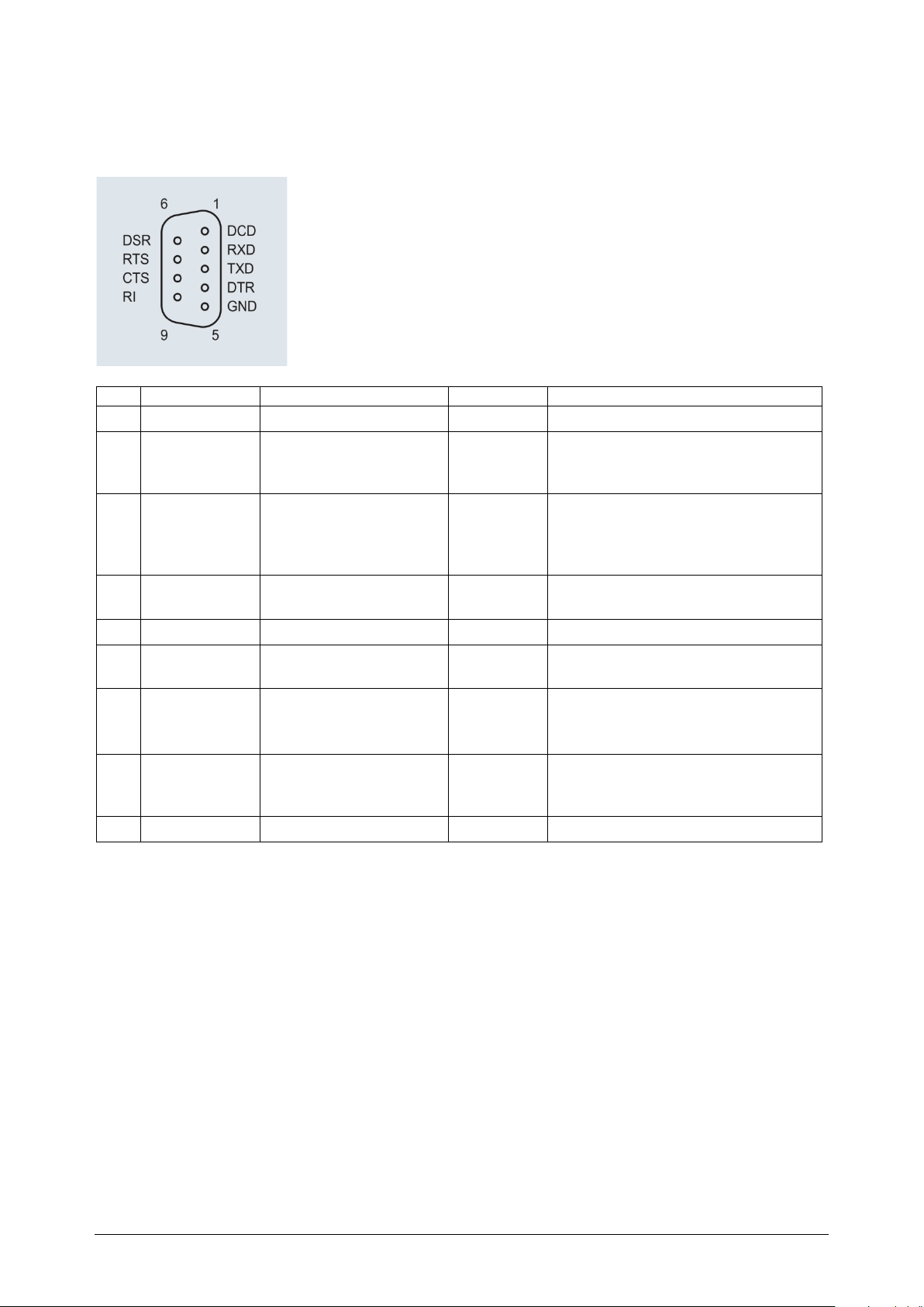
5.2.4 Pin assignment RS232
Pin
Name
Function
Direction
Description
The pin assignment applies for the 1SI serial interface with configured RS232 protocol.
1 DCD Data Carrier Detect Input Carrier signal (modem)
2 RxD Receive Data Input
3 TxD Transmit Data Output
4 DTR Data Terminal Ready Output
5 GND Signal Ground Reference potential
6 DSR Data Set Ready Input
7 RTS Request to send Output
8 CTS Clear to send Input
9 RI Ring indicator Input Ring indicator (modem)
Receive Data
Receiving line is held at logic “1” by
the communication partner
Transmit Data
The 1SI serial interface keeps the
transmission line in the idle state
logic "1"
ON = 1SI serial interface is ready for
operation
Communication partner ready for
operation?
ON = 1SI serial interface ready to
transmit
OFF = does not transmit
Communication partner ready to
receive? The 1SI serial interface
responds on RTS=ON.
TB20 – Serial interface 1SI | Version 1| 13.03.2019 42
Page 43
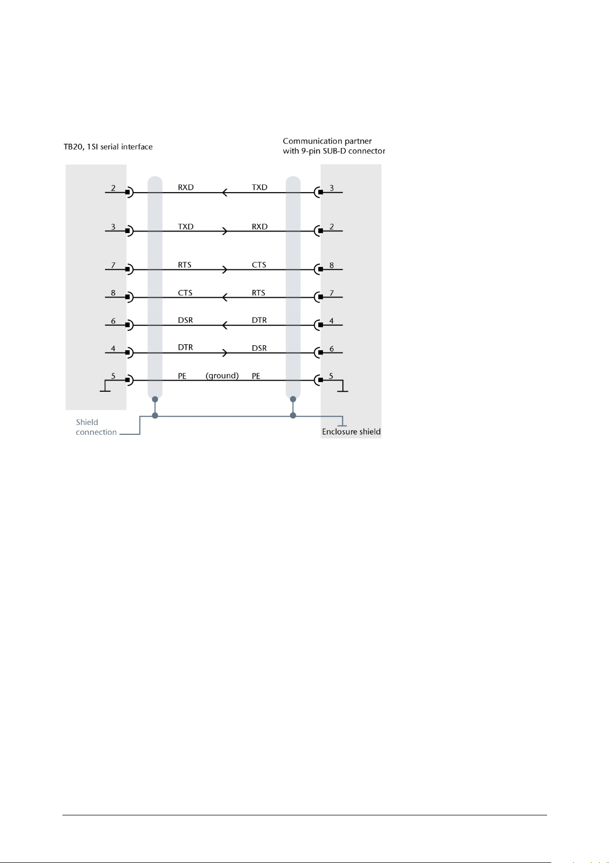
5.2.5 Cable assignment of point-to-point connection RS232
For the point-to-point connection to a RS-232 communication partner with 9-pin SUB-D
terminal, a cable with the pin assignment in accordance with the following image is
required.
TB20 – Serial interface 1SI | Version 1| 13.03.2019 43
Page 44
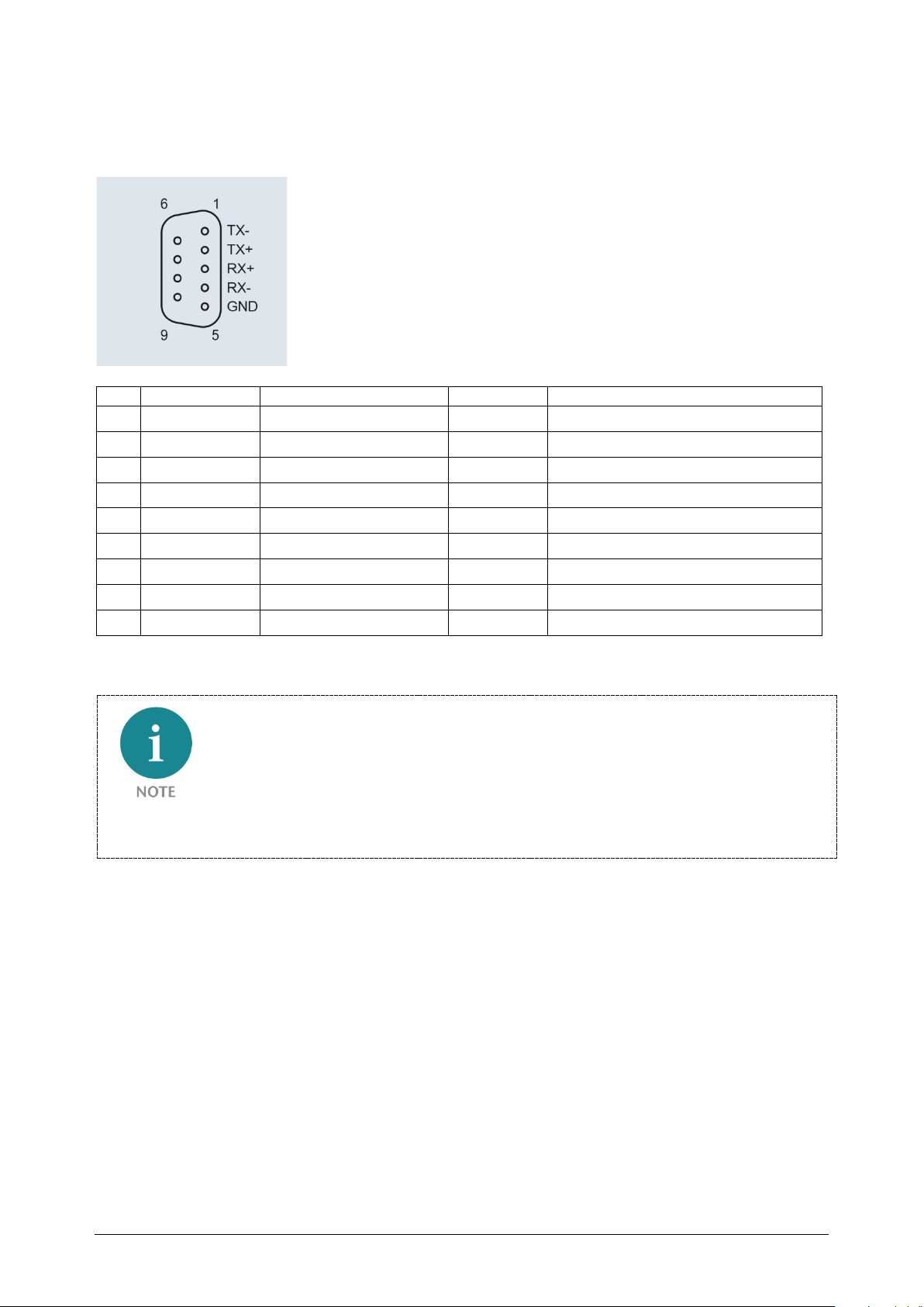
5.2.6 Pin assignment RS422
Pin
Name
Function
Direction
Description
The pin assignment applies for the 1SI serial interface with configured RS422 protocol.
1 TX- Transmit Data (A)- Output Transmit data
2 TX+ Transmit Data (A)+ Output Transmit data
3 RX+ Receive Data (B)+ Input Receive data
4 RX- Receive Data (B)- Input Receive data
5 GND Ground
6
7
8
9 GND
By way of the configuration of the module, a termination with an internal 120Ω terminating
resistor can be activated at the terminals Rx- und Rx+.
TB20 – Serial interface 1SI | Version 1| 13.03.2019 44
Page 45
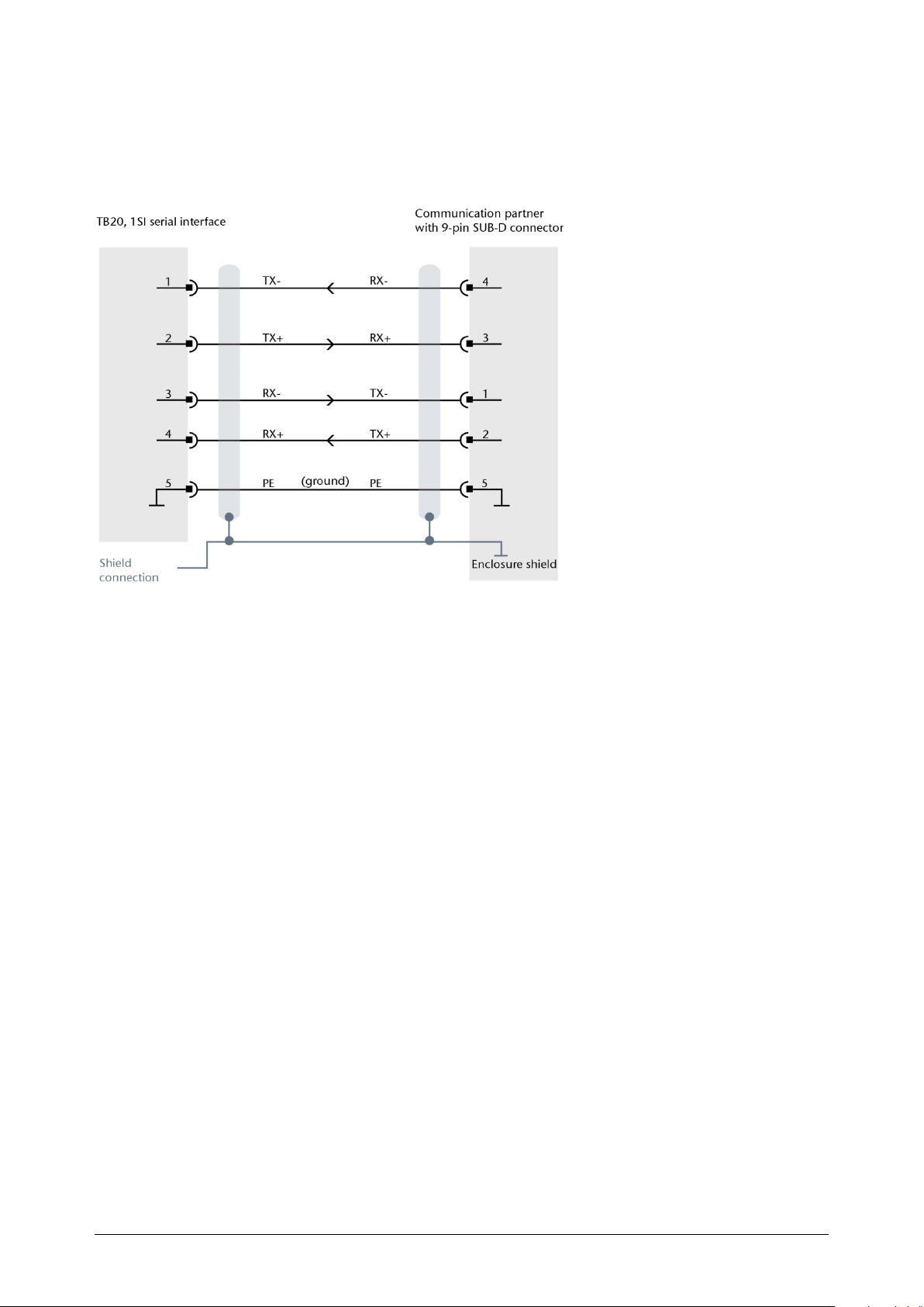
5.2.7 Cable assignment of point-to-point connection RS422
For the point-to-point connection to a RS422 communication partner with 9-pin SUB-D
terminal, a cable with the pin assignment in accordance with the following image is
required.
TB20 – Serial interface 1SI | Version 1| 13.03.2019 45
Page 46
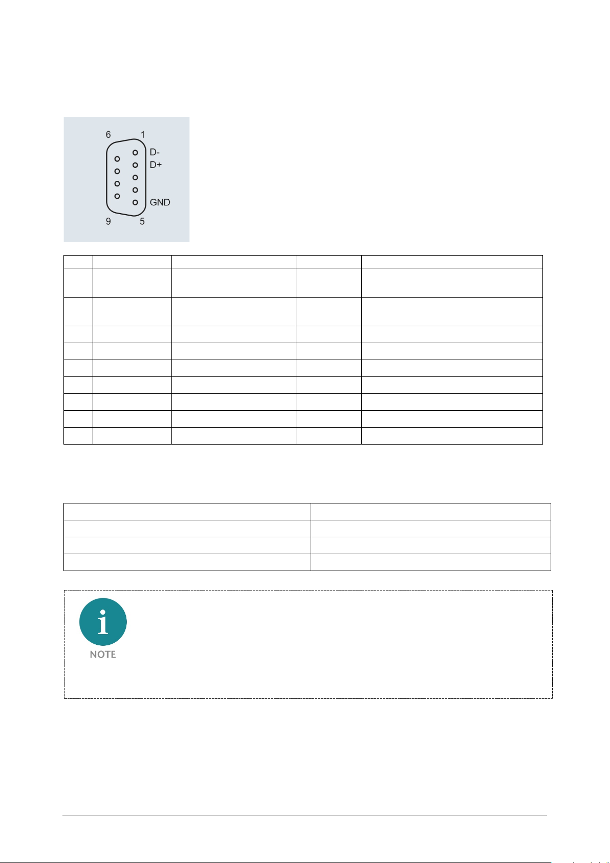
5.2.8 Pin assignment RS485
Pin
Name
Function
Direction
Description
The pin assignment applies for the 1SI serial interface with configured RS485 protocol.
1 D-
2 D+
3
4
5 GND Ground
6
7
8
9
Receive Transmit Data
(R/T)+
Receive Transmit Data
(R/T)-
Receive data/ Transmit data
Receive data/ Transmit data
Recommended cable type: LIYCY 3x2x0.14, drilled paired (Belden8102 or equivalent)
Possible line lengths when using the recommended cable
Cable length Transmission rate
1200 m 19,200 baud
500 m 38,400 baud
250 m 76,800 baud
By way of the configuration of the module, a termination with an internal 120Ω terminating
resistor can be activated at the terminals D- and D+.
TB20 – Serial interface 1SI | Version 1| 13.03.2019 46
Page 47
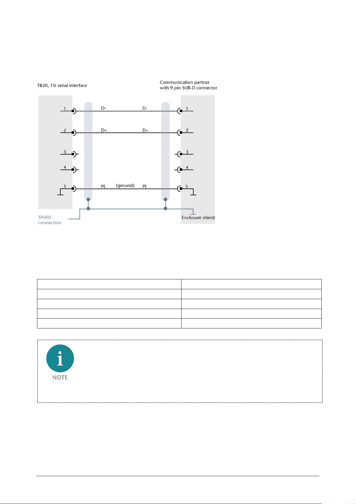
5.2.9 Cable assignment of point-to-point connection RS485
For the point-to-point connection to a RS485 communication partner with 9-pin SUB-D
terminal, a cable with the pin assignment in accordance with the following image is
required.
Recommended cable type: LIYCY 3x2x0.14, drilled paired (Belden8102 or equivalent)
Possible line lengths when using the recommended cable
Cable length Transmission rate
1200 m 19,200 baud
500 m 38,400 baud
250 m 76,800 baud
200 m 115,200 baud
By way of the configuration of the module, a termination with an internal 120Ω terminating
resistor can be activated at the terminals D- and D+.
TB20 – Serial interface 1SI | Version 1| 13.03.2019 47
Page 48

5.2.10 USB interface
Function Firmware update
· Protocol USB 1.01 Device, Full Speed
· Terminal Mini-USB
TB20 – Serial interface 1SI | Version 1| 13.03.2019 48
Page 49
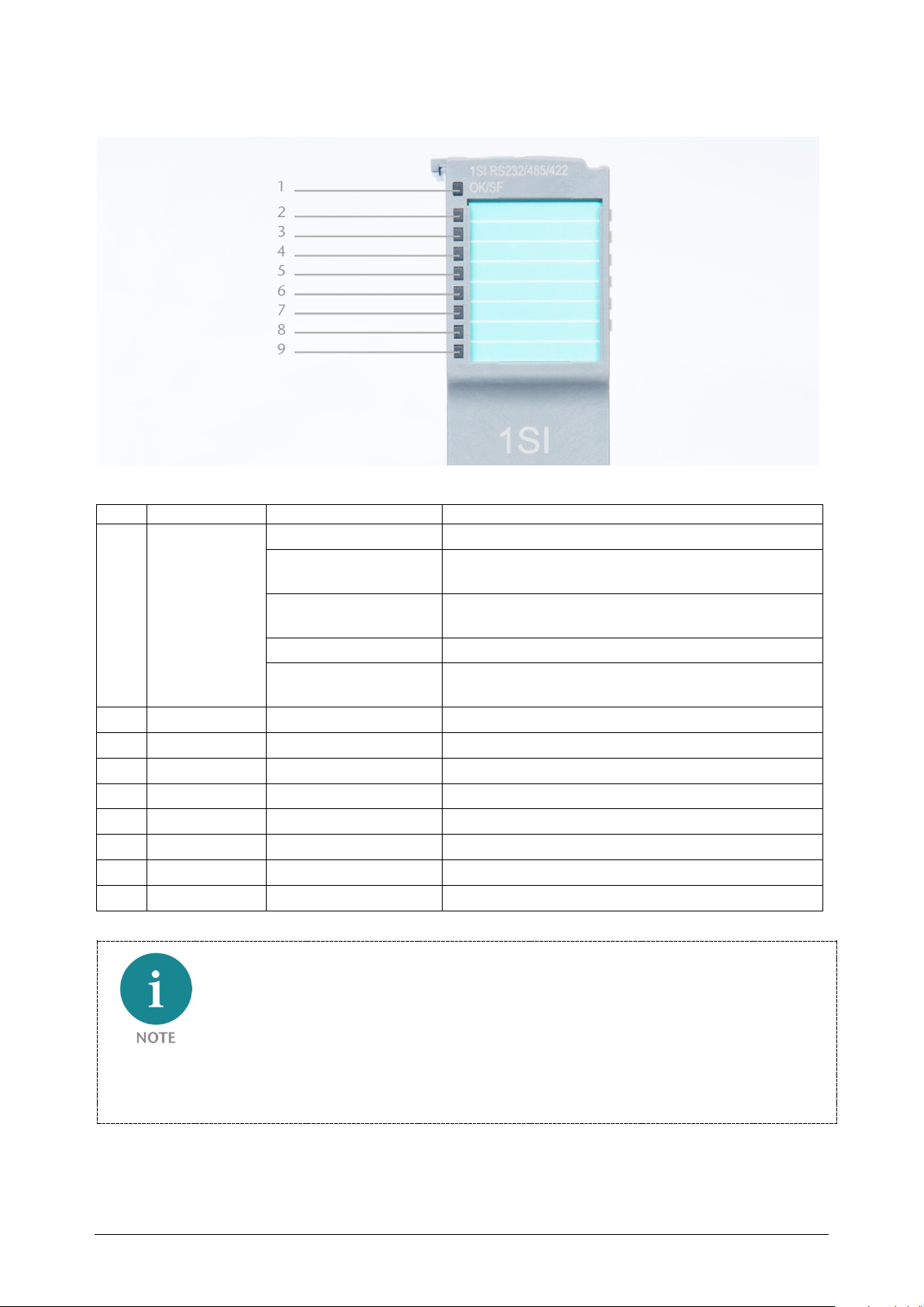
5.2.11 LEDs of the serial interface
LED
Name
Display
Description
1 OK/SF LED Solid blue light The module is running (RUN)
Solid red light The module is indicating a diagnostic error
Flashing red
2 PLC Quickly flashing green Communication with PLC is taking place
3 TxD Solid green light Characters are being transmitted
4 RxD Solid green light Characters are being received
5 CTS Solid green light If CTS signal is high
6 RTS Solid green light If RTS signal is high
7 RS232
8 RS485
9 RS422
Slowly flashing blue
light
Quickly flashing blue
light
The module is stopped (STOP)
The module is idle (IDLE); module’s parameters have
not been configured yet
The module is indicating a parameter assignment
error
IDLE mode (quickly flashing blue LED) indicates modules that have not been added to ongoing
system operation by the coupler. One of the reasons that can cause this is an incorrect
configuration (wrong module model in the slot).
TB20 – Serial interface 1SI | Version 1| 13.03.2019 49
Page 50
6 Commissioning
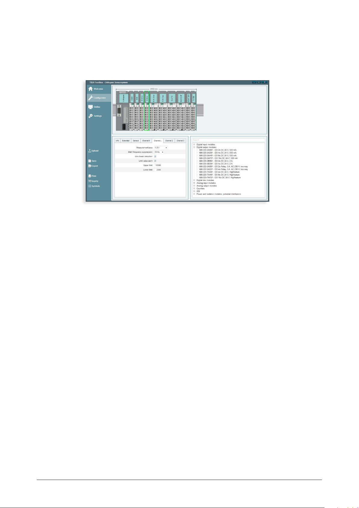
6.1 TB20-ToolBox
In the TB20-ToolBox, positioning and configuration of the parameters of the components
for the planning of a system is possible. Using the USB interface of the bus coupler,
parameters can be configured for the 1SI serial interface.
6.2 Firmware update
A firmware update can be requested from the support department of Helmholz if required
(e-mail: [email protected]).
6.3 Integrating the 1SI serial interface with the GSD file
The serial interface 1SI can be incorporated into the project and parameterized with a GSD
file (PROFIBUS) or GSDML file (PROFINET). The GSD and GSDML files can be downloaded
in the download area under www.helmholz.de.
If the serial interface 1SI is used with a Simatic S7 PLC, the standard handling components
FB2 and FB3 can be used. The data exchange with the serial interface is described in chapter
8.
6.4 Using the serial 1SI serial interface with other PLCs
Depending upon the coupler type, the serial interface 1SI can be parameterized with the
TB20 ToolBox or with coupler-specific methods. The data exchange with the serial interface
1SI is described in chapter 8.
TB20 – Serial interface 1SI | Version 1| 13.03.2019 50
Page 51

7 Parameterization
7.1 ASCII protocol
7.1.1 Features
Using the ASCII protocol, data can be transferred to and from connected communication
partners. The ASCII protocol includes only a bit transmission layer and no data link layer.
With the ASCII protocol, the complete transmission frame is passed from the TB20 master
to the 1SI serial interface. The supplied data is not supplemented with control characters by
the 1SI serial interface.
In the receive direction, the end criterion of a frame is defined by the parameterization of
the module. The structure of the transmission frames may differ from that of the receive
frames.
The ASCII protocol allows data with any structure to be sent and received.
All ASCII characters from 00 to FFh (for transmission with 8 data bits) or from 00 to 7Fh
(for transmission with 7 data bits) can be transferred.
7.1.2 Transmitting data
During transmission, the number of payload data bytes to be transmitted and the payload
data are transferred by the TB20 master. In the payload data, any required start and end
characters may need to be included.
If the end criterion “Expiration of character delay time” needs to be configured with
parameters, the 1SI serial interface keeps a pause between two frames during transmission.
Data may be transferred at any time to the 1SI serial interface. The 1SI serial interface
begins with output only if a time greater than the parameterized character delay time has
passed since the last frame was sent.
7.1.3 Receiving data
For receipt of data with the ASCII protocol, three different end criteria are supported. The
end criterion specifies when a frame was received completely and is defined by
parameterization. Supported end criteria are:
• Reception of the end character(s)
At the end of the frame, there are one or two defined end characters.
• Reception of a fixed number of characters
The length of the receive frames is always identical.
• Expiration of character delay time
The frame has neither a fixed length nor defined end characters. The end of a frame is
defined by a pause on the line (expiration of character delay time). The minimum
values of the character delay time are dependent on the configured baud rate.
TB20 – Serial interface 1SI | Version 1| 13.03.2019 51
Page 52

7.1.4 Minimum character delay time
Baud rate
Minimum character delay time
The minimum delay time is dependent on the baud rate; see table:
110 364 ms
300 130 ms
600 65 ms
1 200 32 ms
4 800 8 ms
9 600 4 ms
14 400 3 ms
19 200 2 ms
38 400 1 ms
57 600 1 ms
76 800 1 ms
115 200 1 ms
7.1.5 Receive buffer
The receive buffer of the RS232 serial interface is 4,096 bytes. Parameterization of the 1SI
serial interface defines whether the receive buffer is deleted at start-up (changing the
operating state from STOP to RUN) and whether overwriting of data is to be prevented in
the receive buffer. Whether the buffering of received frames is enabled or disabled is also
defined.
The receive buffer of the 1SI serial interface is designed as a ring buffer:
• If several frames are stored in the receive buffer of the 1SI serial interface, the oldest
frame is always transferred to the TB20 master.
• If only the most recent message frame is to be transferred to the master, the buffer
overwrite protection must be canceled in the parameterization, and the parameter
“Dynamic frames” must be disabled.
7.1.6 Reception error
If a reception error (parity error) is detected by the 1SI serial interface upon receipt of a
frame, the entire frame is discarded upon expiration of the character delay time or the
receipt of the end character and the corresponding error is reported to the TB20 master.
If the end criterion “Receipt of a fixed number of characters” is set, expiration of the
character delay time before reaching the parameterized number of characters generates a
reception error, which is reported to the TB20 master.
TB20 – Serial interface 1SI | Version 1| 13.03.2019 52
Page 53
7.1.7 RS232 escort lines
The 1SI serial interface supports the following escort lines:
• DCD (Input) Data carrier detect; data carrier recognized
• DTR (Output) Data terminal ready; 1SI serial interface is ready for operation
• DSR (Input) Data set ready; communication partner ready for operation
• RTS (Output) Request to send; 1SI serial interface is ready to transmit
• CTS (Input) Clear to send; communication partner can receive data from the 1SI
serial interface (response to RTS = ON)
After the 1SI serial interface is switched on, the output signals are in the OFF state
(inactive).
7.1.8 Control of the RS232 escort lines
The control of the control signals DTR/DSR and RTS/CTS is defined by the
parameterization in the ToolBox or can be controlled by the user program of the bus
master.
The following modes are supported:
• Automatic control of all escort lines
• Data flow control via RS232 escort lines (RTS/CTS)
• No control
7.1.9 Automatic control of the RS232 escort lines
For automatic control of escort signals, only half-duplex operation is possible!
Automatic operation of the RS232 escort signals has the following functions:
• Once the 1SI serial interface is put into an operating mode with automatic use of the
RS-232 escort signals through parameterization, it sets the RTS lines to OFF and the
DTR line to ON.
Transmitting and receiving of frames is only possible after the DTR line is set to ON. As
long as DTR remains set to OFF, no data is received on the RS232 interface. A transmit
job is aborted with the corresponding error.
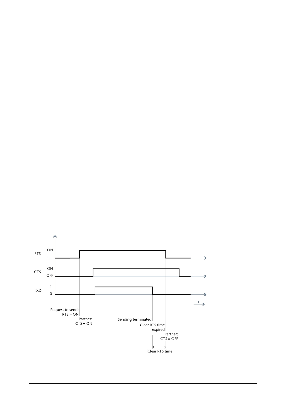
• When a transmit job is pending, RTS is set to ON, and with CTS = ON, the data is
transmitted on the RS232 interface.
• If during transmission within the data output time the CTS line is not set to ON, or if
CTS changes to OFF during the transmission process, the transmit job is aborted and
an appropriate error is sent to the TB20 master.
• After the data is transmitted, the RTS line is set to OFF after expiration of the
parameterized RTS removal time. The 1SI serial interface does not wait for CTS to
change to OFF.
TB20 – Serial interface 1SI | Version 1| 13.03.2019 53
Page 54
• Data can be received via the RS232 interface as soon as the DSR line is set to ON. If the
receive buffer of the 1SI serial interface threatens to overflow, there is no reaction of
the 1SI serial interface.
• If DSR changes from ON to OFF, both a running transmit job and the reception of data
will be aborted and a corresponding error will be sent to the TB20 master.
7.1.10 Data flow control via RS232 escort lines (RTS/CTS)
The handshake procedure via RS232 escort lines controls the data flow between the 1SI
serial interface and the communication partner. The handshake procedure makes it
possible to prevent having data lost during transmission when the speed of data processing
of the communication partner differs.
The data flow control via RS232 escort lines (RTS/CTS) is implemented in the RS232 serial
interface as follows:
• If the 1SI serial interface is parameterized in the operating mode “Data flow control via
RS232 escort lines,” the 1SI serial interface sets the RTS line to ON.
• If the receive buffer overflows with more than 4,096 bytes or 250 frames, the 1SI serial
interface sets the RTS line to OFF. If the communication partner nonetheless continues
to transmit, a corresponding error is sent to the TB20 master and the received data of
the last frame is discarded.
• If a frame is read by the bus master and the receive buffer is ready to receive, the 1SI
serial interface sets the RTS line to ON.
• If the control signal CTS is set to OFF, the 1SI serial interface interrupts the
transmission. If CTS is not set to ON after the configured time, the transmission is
aborted and an error message is generated.
• If CTS is set back to ON within the waiting time for CTS ON, the remaining bytes of
the previously aborted frame are sent.
TB20 – Serial interface 1SI | Version 1| 13.03.2019 54
Page 55

7.1.11 Data flow control via XON and XOFF / software handshake
The handshake procedure controls the data flow between the 1SI serial interface and the
communication partner. Sending characters makes it possible to prevent having data lost
during transmission when the speed of data processing of the communication partner
differs.
The data flow control via software handshake is implemented in the 1SI serial interface as
follows:
• If the 1SI serial interface is configured in the operating mode with “Data flow control
via XON and XOFF", the 1SI serial interface transmits the XON character.
• If the receive buffer overflows with more than 4,096 bytes or 250 frames, the 1SI serial
interface sends the XOFF character. If the communication partner nonetheless
continues to transmit, a corresponding error is sent to the TB20 master and the
received data of the last frame is discarded.
• If a frame is fetched by the bus master and the receive buffer is ready to receive, the 1SI
serial interface transmits the XON character.
• If the 1SI serial interface receives the XOFF character, further transmission is aborted. If
no XON is received after the configured time, the transmission is aborted and an error
message is generated.
• If the XON character is sent within the waiting time, the remaining bytes of the
previously aborted frame are sent.
7.1.12 Data flow control via manual reading and control of RS-232 escort lines
The RS-232 escort lines can be read with the help of the function blocks FB4 S_VSTAT. The
information is provider to the user via the respective block parameters.
The function block FB5 S_VSET makes it possible to use the parameter inputs of the block
to set or reset the interface outputs accordingly.
When configuring the modules with automatic operation of the RS-232 escort lines or the
data flow control using RTS/CTS, manual control of the named escort lines is not possible.
The reading of all RS-232 escort lines with the help of the FB S-VSTAT is not affected by
this.
TB20 – Serial interface 1SI | Version 1| 13.03.2019 55
Page 56
7.2 ASCII configuration
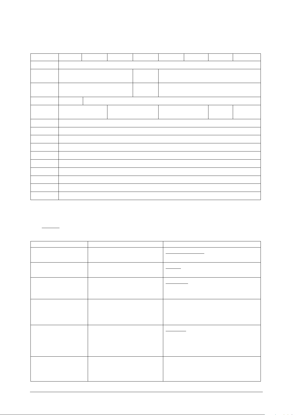
Parameters
Description
Value range
3 = 1200
Parameters for operating mode ASCII: 19 bytes
7 6 5 4 3 2 1 0
Par 0 Operating mode: ASCII-8 or 32 byte
Par 1 Reserved
Par 2 Reserved
Par 3 reserved Baud rate
Par 4 Data bits Stop bits Parity
Par 5 XON character
Par 6 XOFF characters
Par 7-8 Waiting time on XON
Par 9-10 Waiting time for CTS = ON
Par 11-12 Waiting time for RTS = OFF
Par 13 Frame end
Par 14-15 Character delay time
Par 16 End character 1
Par 17 End character 2
Par 18 Frame length
Termina-
tion
Dyn.
frames
Agreements are needed for the serial data transfer between the two communication
partners.
Interface
Data flow control
Buffer at
startup
Overwrite
buffer
The default settings are underlined.
Operating mode 1 = ASCII (8 byte)
2 = ASCII (32 byte)
Termination
Interface 1 = RS232
Dynamic frames
Data flow control
Baud rate
Internal termination with 120
Ohm. Irrelevant for RS232
With dynamic frames, the 1SI
serial interface can buffer
several messages of different
lengths.
The transmission is
synchronized through the data
flow control if the
communication partners are
working at different speeds.
Transmission speed in bits per
second
0 = No
1 = Yes
2 = RS422 (full-duplex)
3 = RS485 (half-duplex)
1 = Yes / 0 = No
0 = None
1 = XON/XOFF
2 = RTS/CTS
3 = Automatic detection
0 = 110
1 = 300
2 = 600
TB20 – Serial interface 1SI | Version 1| 13.03.2019 56
Page 57
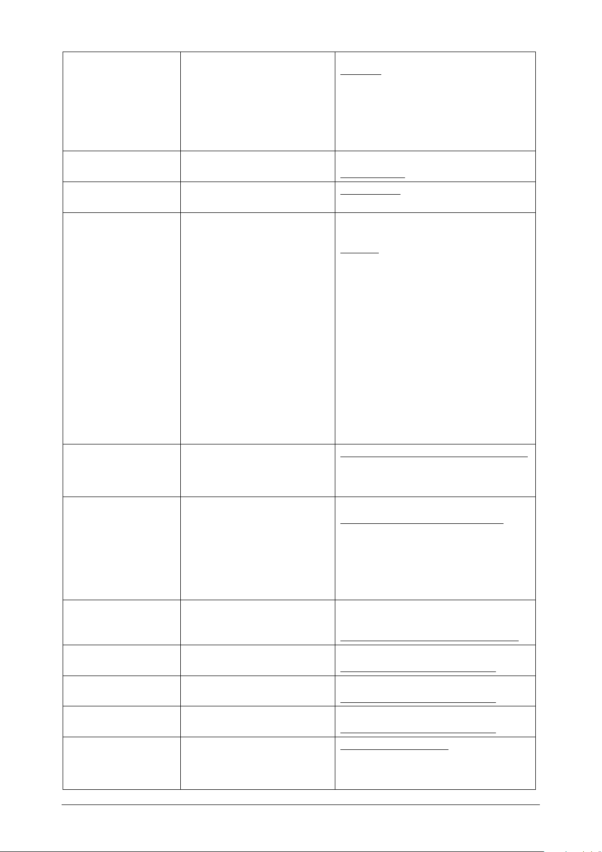
4 = 4800
time
5 = 9600
6 = 14400
7 = 19200
8 = 38400
9 = 57600
10 = 76800
11 = 115200
Data bits Bits per character 1 = 7 data bits
2 = 8 data bits
Stop bits
Parity
Number of bits that mark the
end of the information words
Parity check is used to detect
incorrectly transmitted
information words
None: Data is sent without a
parity bit.
1 = 1 stop bit
2 = 2 stop bits
0 = None
1 = Odd
2 = Even
3 = Any
Odd: The parity bit is set; the
total number of data bits with
the signal state “1” is odd,
including the parity bit
Even: The parity bit is set; the
total number of data bits with
the signal state “1” is even,
including the parity bit
Any: Parity is not checked when
data is received. When
transmitting, it behaves like
with the setting "Even"
Buffer at startup
The receive buffer is
automatically cleared when the
operating mode is changed
0 = Delete the receive buffer upon startup
1 = Do not delete the receive buffer upon
startup
from STOP to RUN
Overwrite buffer
It is possible to prevent
buffered frames from being
0 = Overwriting of the buffer
1 = Prevent overwriting of the buffer
overwritten when the 1SI serial
interface receives a new frame,
but the receive buffer has not
yet been deleted.
This prevents old received
frames from being lost.
XON / XOFF character: 0x00 to 0xFF with 8 data bits
0x00 to 0x7F with 7 data bits
Default XON: 0x11, default XOFF: 0x13
Waiting time on XON 20-655350 in increments of 10 ms
Default: 200 (10 * 200 = 2000 ms)
Waiting time for
CTS = ON
Waiting time for RTS =
OFF:
Frame end
20 to 655350 in increments of 10 ms
Default: 200 (10 * 200 = 2000 ms)
0 to 655350 in increments of 10 ms
Default: 200 (10 * 200 = 2000 ms)
Detecting the end of the
reception frame
Expiration of character delay
0 = character delay time
1 = reception of the end character
2 = number of characters
TB20 – Serial interface 1SI | Version 1| 13.03.2019 57
Page 58

The frame end is recognized
Character delay time
End character 1
End character 2
Frame length upon
receipt
when the character delay time
has expired.
Reception of the end character
The frame end is recognized
when the end characters are
received.
Perception of a fixed number of
characters
The frame end is recognized by
the frame length. All frames to
be received must have the
same length.
Time that may elapse between
the receipt of two characters
The selected end characters
limit the length of the frame
Only takes effect with the end
criterion “Receipt of the end
character.”
The selected end characters
limit the length of the frame
Only takes effect with the end
criterion “Receipt of the end
character.”
Frame length for data with a
fixed number of characters.
1–65535 ms
Default: 4 ms
0x00 to 0xFF with 8 data bits
0x00 to 0x7F with 7 data bits
Default: 0x03
0x00 to 0xFF with 8 data bits
0x00 to 0x7F with 7 data bits
Default: 0x0
1–224 characters
Default: 100
TB20 – Serial interface 1SI | Version 1| 13.03.2019 58
Page 59

7.3 3964R protocol
The 3964R protocol controls the data transfer for a point-to-point connection between the
serial interface 1SI and a communication partner connected to this serial interface. The
3964R protocol expands the bit transmission with a backup layer.
7.3.1 Control characters
The 3964R protocol adds control characters to the payload data during data transmission
(backup layer). With these control characters, both communication partners can check
whether the data has arrived completely and without errors.
In the case of the 3964R protocol, the following control characters are used:
• STX (02H): Start of Text;
Start of the character sequence to be transmitted
• DLE (10H): Data Link Escape;
Data transmission switch (positive acknowledgment)
• ETX (03H): End of Text;
End of the character sequence to be transmitted
• BCC: Block Check Character;
Block check sum character
• NAK (15H): Negative Acknowledge;
Negative response
7.3.2 Conduct upon occurrence of the character DLE in the payload data
If the payload data to be transmitted contain the control character DLE, this is transmitted
twice (DLE doubling) to differentiate from the control character DLE when establishing and
clearing the connection on the transmission line. The recipient reverses the DLE doubling
again.
7.3.3 Block checksum
In the case of the transmission protocol 3964R, data security is increased by an additionally
sent BCC (Block Check Character). All data bytes are XOR-linked for the calculation of the
block check sum. The formation begins with the first payload data byte (1st byte after the
control character STX) and ends after the character DLE ETX when clearing the connection.
The block check sums character is transmitted as the last character.
In the case of a DLE doubling (see chapter 7.3.2), the DLE character is incorporated twice
into the BCC formation.
TB20 – Serial interface 1SI | Version 1| 13.03.2019 59
Page 60
7.3.4 Transmitting data
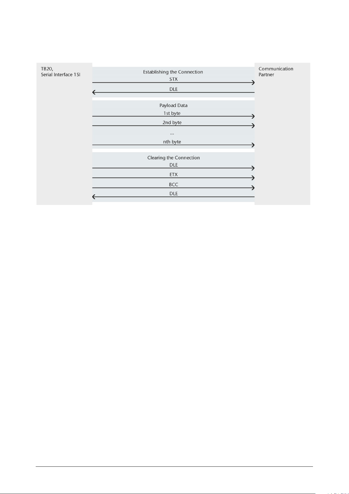
Data transmission from the 1SI serial interface to the serial communication partner
7.3.5 Establishing a connection
In order to establish the connection, the serial interface 1SI transmits the control character
STX. If the communication partner answers with the character DLE prior to expiration of
the acknowledgment delay time, the serial interface 1SI switches to transmission mode. If
the communication partner answers with NAK, any other character (except DLE) or if the
acknowledgment delay time expires without a reaction, the serial interface 1SI repeats the
establishing of the connection. Following the configured number of connection attempts,
the serial interface 1SI cancels the establishing of a connection and transmits the character
NAK to the communication partner. The serial interface 1SI also reports the error to the
TB20 master.
7.3.6 Payload data transmission
If a connection is successfully established, the payload data contained in the output buffer
of the serial interface 1SI are sent to the communication partner together with the selected
transmission parameters (baud rate, number of data bits, ...). This monitors the time
interval of the arriving characters. The distance between two characters may not exceed the
character delay time.
7.3.7 Clearing a connection
If the communication partner transmits the character NAK during an ongoing
transmission, the serial interface 1SI cancels the block and repeats it in the manner
described above. In the case of a different character, the serial interface 1SI initially waits
for the expiration of the character delay time and then transmits NAK in order to bring the
communication partner to an idle state. The serial interface 1SI then begins transmitting
again with the STX establishing of a connection. After the buffer content is transmitted,
the serial interface 1SI adds the characters DLE, ETX and the block checksum BCC as end
code and waits for an acknowledgment character (DEL). If the communication partner
transmits the character DLE within the acknowledgment delay time, the data block has
TB20 – Serial interface 1SI | Version 1| 13.03.2019 60
Page 61
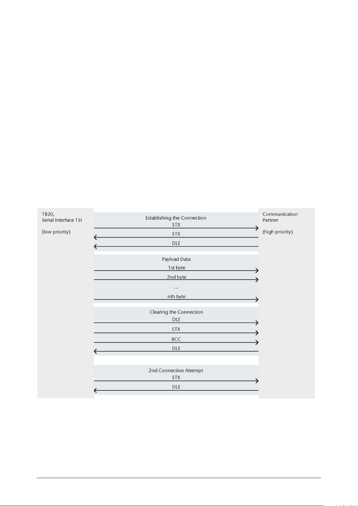
been accepted without errors. If the communication partner answers with NAK, any other
character (except DLE), a distorted character, or if the acknowledgment delay time expires
without a reaction, the serial interface 1SI repeats the establishing of the connection STX.
Following the expiration of the configured number of transmission attempts to send the
data block, the serial interface 1SI cancels the process and sends NAK to the
communication partner.
The serial interface 1SI also reports the error to the TB20 master.
7.3.8 Initialization conflict
If a communication participant doesn't respond to the transmission query (character STX)
of the communication partner with the acknowledgment DLE or NAK within the
acknowledgment delay time, but instead with the character STX, an initialization conflict
has occurred. Both devices are attempting to carry out an existing transmission job. The
device with the lower priority withdraws its transmission job and responds with the
character DLE.
The device with the higher priority transmits its data in the previously described manner.
Following the clearing of the connection, the device with the lower priority carries out its
transmission job.
The priority of the serial interface 1SI is determined by configuration.
TB20 – Serial interface 1SI | Version 1| 13.03.2019 61
Page 62
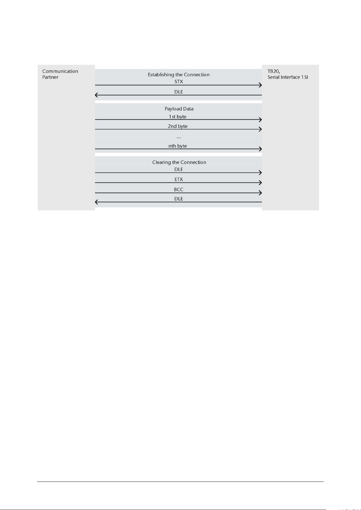
7.3.9 Receiving data
Data transmission from the communication partner to the serial interface 1SI
7.3.10 Establishing a connection
In the idle state, when no transmission job needs to be processed, the serial interface 1SI
waits for the connection to be established by the communication partner. If the serial
interface 1SI receives any character (except STX or NAK) while in the idle state, it waits for
the expiration of the character delay time and then transmits the character NAK.
7.3.11 Payload data transmission
If the serial interface 1SI receives the character STX and has an empty receive buffer
available, it responds with DLE. Incoming receive characters are now filed in the receive
buffer. If two consecutive DLE characters are received, only one DLE character is
incorporated into the receive buffer.
After each receive character, the next character is waited for during the character delay
time. If the character delay time expires without receiving, the NAK character is sent to the
communication partner. The serial interface 1SI also reports the error to the TB20 master.
If during the establishing of the connection with STX there is no empty receive buffer
available, a waiting period of 400 ms starts. If following this period there is still no empty
receive buffer available, the serial interface 1SI reports the error (see chapter 9). The serial
interface 1SI also transmits the character NAK and returns to the idle state. The serial
interface 1SI otherwise transmits the character DLE and receives the data in the manner
described above.
TB20 – Serial interface 1SI | Version 1| 13.03.2019 62
Page 63

7.3.12 Clearing a connection
If transmission errors (lost character, frame error, parity error, etc.) occur during reception,
reception continues until the clearing of a connection and NAK is then sent to the
communication partner. A repetition is then anticipated. If the block still can't be received
without errors after the number of repeat attempts indicated during configuration, or if the
repetition is not started by the communication partner within a block waiting period of 4 s,
the serial interface 1SI cancels the reception. The serial interface 1SI also reports the error to
the TB20 master.
If the serial interface 1SI recognizes the character sequence DLE ETX BCC, the reception is
ended and the received block check character BCC is compared with the internally created
checksum. If the block check character is correct and no other reception errors have
occurred, the serial interface 1SI transmits the character DLE and returns to the idle state.
In the event of an incorrect BCC or another reception error, the serial interface 1SI sends
NAK to the communication partner and waits the block waiting period of 4 s before
making a new attempt. If the block can't be received following the configured number of
transmission attempts, or if no further attempt is made during the block waiting period,
the serial interface cancels the 1SI. The serial interface 1SI also reports the error to the TB20
master.
Note: As soon as it is ready for operation, the serial interface 1SI transmits the character
NAK once to the communication partner to bring it to the idle state.
TB20 – Serial interface 1SI | Version 1| 13.03.2019 63
Page 64
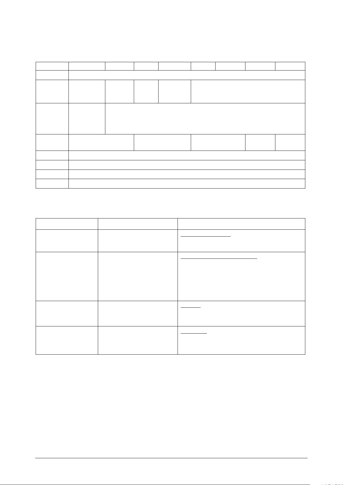
7.3.13 Configuration of 3964R protocol
Parameters
Description
Value range
Operating mode
4 = 3964 (8 byte)
Block check:
The transmission is
0 = no block check (3964)
Termination
0 = No
Interface
Parameters for operating mode 3964(R): 10 bytes
7 6 5 4 3 2 1 0
Par 0 Operating mode: 3964(R) - 8 or 32 byte
Par 1
Par 2
Par 3 Data bits Stop bits Parity
Par 4–5 Character delay time
Par 6-7 Acknowledgment delay time
Par 8 Connection attempts
Par 9 Transmission attempts
Diagnosis
alarm
Preliminary
assignment
Reception
line
Break
detectio
n
Block
check
Termina-
tion
Baud rate
Interface
Buffer at
startup
Agreements are needed for the serial data transfer between the two communication
partners.
Priority
(UINT8)
synchronized through
the data flow control if
the communication
partners are working at
different speeds.
Internal termination
with 120 Ohm.
(Irrelevant for RS232)
8 = 3964 (32 byte)
1 = block check (3964R)
1 = Yes
1 = RS232
2 = RS422
TB20 – Serial interface 1SI | Version 1| 13.03.2019 64
Page 65
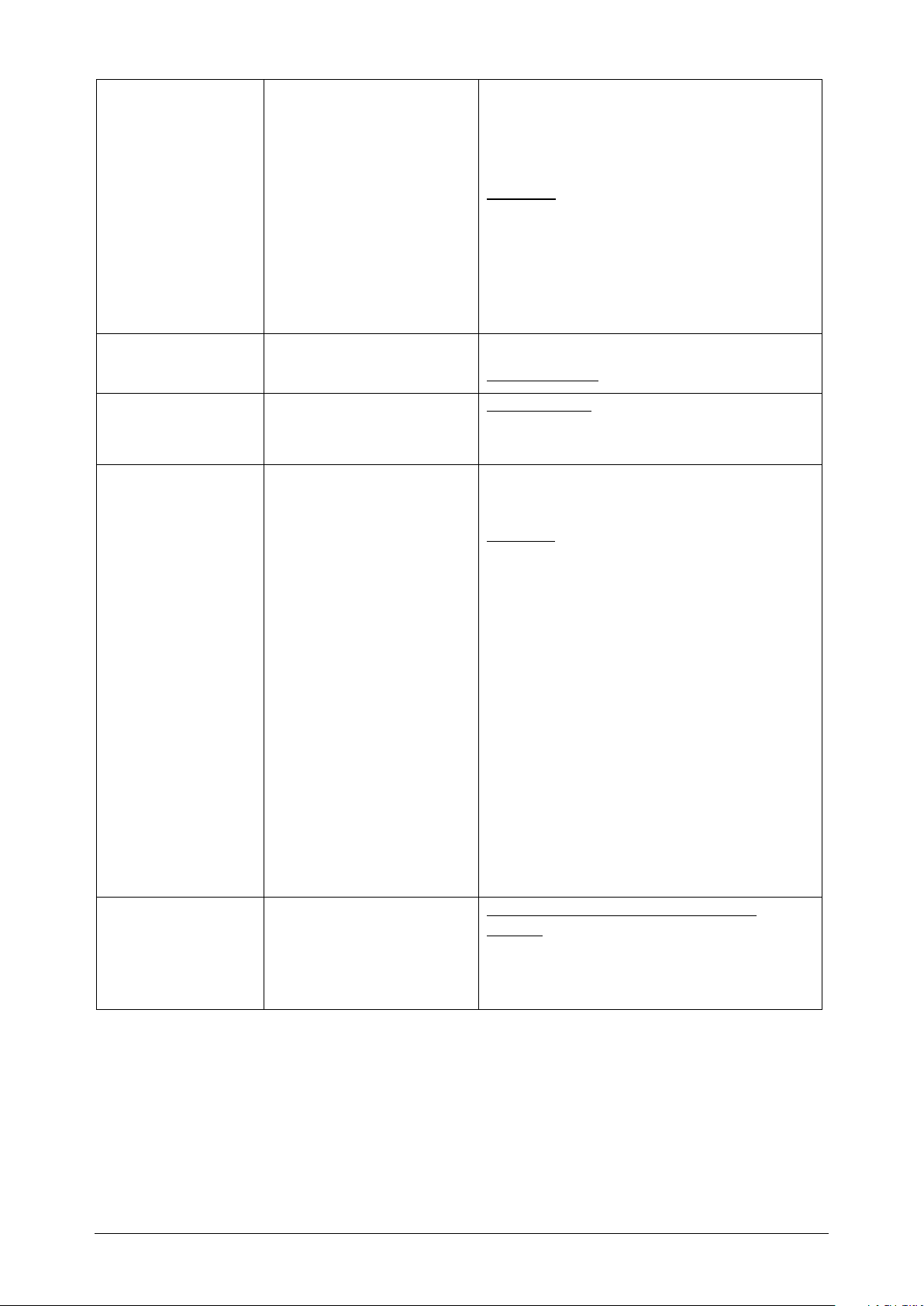
Baud rate
Transmission speed in
bits per second
0 = 110
Data bits
Bits per character
1 = 7 data bits
Stop bits
Number of bits that
1 = 1 stop bit
Parity
Parity check is used to
0 = None
Buffer at startup
The receive buffer is
0 = Delete the receive buffer upon
1 = 300
2 = 600
3 = 1200
4 = 4800
5 = 9600
6 = 14400
7 = 19200
8 = 38400
9 = 57600
10 = 76800
11 = 115200
2 = 8 data bits
mark the end of the
information words
detect incorrectly
transmitted information
words
None: Data is sent
without a parity bit.
Odd: The parity bit is
set; the total number of
data bits with the signal
state “1” is odd,
including the parity bit
Even: The parity bit is
set; the total number of
data bits with the signal
state “1” is even,
including the parity bit
Any: Parity is not
checked when data is
received.
2 = 2 stop bits
1 = Odd
2 = Even
3 = Any
TB20 – Serial interface 1SI | Version 1| 13.03.2019 65
automatically cleared
when the operating
mode is changed from
STOP to RUN
startup
1 = Do not delete the receive buffer
upon startup
Page 66

Character delay
time
1 – 65,535 ms
Acknowledgment
20 - 655.350 ms
Connection
1 – 255
Transmission
1 – 255
Priority
0 = Low
Default: 200 (10 * 200 = 2000 ms)
delay time
attempts
attempts
The default settings are underlined.
Process alarms:
- None
Diagnosis capabilities:
- Configuration errors
- Underflow / overflow buffer
Default: 200 (10 * 200 = 2000 ms)
Default: 6
Default: 6
1 = High
- Internal module error
- Message errors
TB20 – Serial interface 1SI | Version 1| 13.03.2019 66
Page 67
8 Reference data for communication with bus masters
8.1 Data exchange between the master and the serial interface
To operate the 1SI serial interface behind a communications module, corresponding
function modules must be provided in the master controller program.
The 1SI serial interface transmits data of 4, 8, or 32 bytes, input or output, with consistency
over the entire length. The 1SI serial interface uses the 4-, 8-, or 32-byte input/output
memory for data transmission to and from the master via a bus.
Inputs (data/feedback): n bytes. n = 8 or 32, depending on operating mode
ID 0 Coordination byte
ID 1 Input data byte 0
ID 2 Input data byte 1
ID .. Input data byte ..
ID .. Input data byte ..
ID n-1 Input data byte n-2
7 6 5 4 3 2 1 0
Outputs (control interface): n bytes. n = 8 or 32, depending on operating mode
7 6 5 4 3 2 1 0
OS 0 Coordination byte
OS 1 Output data byte 0
OS 2 Output data byte 1
AB .. Output data byte ..
AB .. Output data byte ..
AB n-1 Output data byte n-2
The master writes data to the inputs and outputs and reads data from the inputs and
outputs:
• In the first byte of the output memory of the 1SI serial interface, the master releases a
job to the 1SI serial interface.
• The 1SI serial interface transmits the job code in the input memory and thus accepts
the job.
• The master exchanges data via segments 3, 7, or 31 bytes (as many segments as are
required in accordance with the I/O size) until all data of the job is transferred.
The first byte of the segment is a coordination byte, which serves to synchronize the
transfer of the segment between the master and the 1SI serial interface; see the figure
below. The other bytes of the I/O memory contain data of the job.
TB20 – Serial interface 1SI | Version 1| 13.03.2019 67
Page 68
Data exchange between the CPU and the 1SI serial interface:
Transmission of data from the master
to the 1SI serial interface
Transmission of the data from the
1SI serial interface to the master
Byte Content
0 Coordination byte
1 Data byte 0
2 Data byte 1
… …
n Data byte N
Byte Content
0 Coordination byte
1 Data byte 0
2 Data byte 1
… …
n Data byte N
n = 3, 7, or 31, depending on the module variant of the 1SI serial interface
TB20 – Serial interface 1SI | Version 1| 13.03.2019 68
Page 69
8.2 Coordination byte
Byte segment
Description
The coordination byte (byte 0) synchronizes the data transfer between the master and the
1SI serial interface.
Table: Coordination byte
Job byte written
by the master
Bit 7
Job code Is set by the CPU to initiate a job.
Sequence
number
Fault
Job byte written
by the 1SI serial
interface
Bit 7
Job code Is taken over by the 1SI serial interface to acknowledge that the job was accepted.
Sequence
number
Fault
Bit 7 6 5 4 3 2 1 0
Reserve Job code Fault Sequence number
Reserved for special applications. For evaluations of the coordination byte, this bit
needs to be hidden.
Send job: Is increased by the bus master to 1 when the bus master sends another
segment to the 1SI serial interface
or
Receive job: Is taken each time from input byte 0 of the bus master when the bus
master of the interface module receives a new segment in the correct order.
Indicates the last valid sequence number when the error bit is set. (Value goes
from 1 to 7).
Is set by the bus master to indicate that a segment has not been received in the
correct order. The sequence number field indicates the last valid sequence
number.
Bit 7 6 5 4 3 2 1 0
Reserve Job code Fault Sequence number
Reserved for special applications. For evaluations of the coordination byte, this bit
needs to be hidden.
Send job: Is taken each time from output byte 0 of the 1SI serial interface if the
module receives a new segment in the correct order from the bus master. Indicates
the last valid sequence number when the error bit is set.
Receive job: Is increased by 1 by the module if the module sends another segment
of the bus master (the value goes from 1 to 7).
The error bit of the receiver is monitored by the sender for a segmented
transaction. Reactions when the error bit is set:
� Sender bus master (send job): The bus master sends the segments again, starting
with the next segment after the number reported by the receiver.
� Sender module (receive job): The 1SI serial interface interrupts transmission of
the Rx frame to the user with error message 0x0551 in the status word. The 1SI
serial interface waits for acknowledgment of the error message (idle). After
completion of the current error sequence, the aborted Rx frame is again reported
or made available for collection by the user.
TB20 – Serial interface 1SI | Version 1| 13.03.2019 69
Page 70
8.3 Definitions of the job codes
Bit 6 5 4 Hex. value
The jobs are assigned to bits 4 to 6 in the coordination byte.
Table: Job codes
0 0 0 0H Idle
0 0 1 1H Send
0 1 0 2H Receive
0 1 1 3H Read V.24 signal status
1 0 0 4H Write V.24 signals
1 0 1 5H
1 1 0 6H Reserved
1 1 1 7H Job sent acknowledgment
Rules for writing job codes
For writing job codes in the coordination byte, the following rules apply, with which the
bus master and the 1SI serial interface can synchronize the data transfers:
Transfer parameters:
Additional parameters can be set with this job.
• Before the user program of the bus master can write a job code in the output
coordination byte, it needs to see an idle code from the input coordination byte of the
1SI serial interface.
• Before the user program of the bus master can write the first segment in the output
byte 1 ... n, it must see the acknowledgment code (that is, the assumed job code) in the
input coordination byte of the assembly.
• If the user program sees job acknowledgment codes that differ from those sent by the
user program, it may not write to the output byte 0 ... n until it has again seen an idle
code from the input coordination byte of the 1SI serial interface. This happens when
two separate jobs are executed in the same cycle, both jobs see the idle code, and both
write a different job code to the output byte. Because of the asynchronous cycle
between the bus master cycle and the bus cycle, it is not ensured that the job will reach
the 1SI serial interface first. Therefore, each job must be able to wait for the end of
another job before it is processed.
Definitions of the status words
In the following examples of data transmissions, the 1SI serial interface uses the bytes 1
and 2 for the status message in some responses to the bus master.
TB20 – Serial interface 1SI | Version 1| 13.03.2019 70
Page 71

Reception status of the 1SI serial interface
Status
Meaning
When the 1SI serial interface is idle (job acknowledgment byte 0 = 00
), it displays its
H
reception status. The reception status is stored in bytes 1 and 2.
Table: Reception status
0000H No received message available
0001H Received message or receive frame available
0B01H The receive buffer is filled to more than 2/3rds.
Order of the bytes in the word
For data transfers between the bus master and the 1SI serial interface, the byte with the
highest value is transmitted first in all 16-bit words (such as status and length).
TB20 – Serial interface 1SI | Version 1| 13.03.2019 71
Page 72
8.3.1 Sequence for sending data from the bus master to the 1SI serial interface
Bus
cycle
Bus master writes to
Bus master reads from
1.
User program reads the idle code
Byte 0 1 2 3 4 5 6
7
00H
nnnnH
xxH
xxH
xxH
xxH
xxH
Ack.
Status
No meaning
Bus master writes the job for sending
Byte 0 1 2 3 4 5 6
7
10H
xxH
xxH
xxH
xxH
xxH
xxH
xxH
Job
No meaning
2.
User program continues to read the idle code
Byte 0 1 2 3 4 5 6
7
00H
nnnnH
xxH
xxH
xxH
xxH
xxH
xxH
Ack.
job
Status
No meaning
Bus master repeats the job for sending
Byte 0 1 2 3 4 5 6
7
10H
xxH
xxH
xxH
xxH
xxH
xxH
xxH
Job
No meaning
3.
User program reads the response from the 1SI serial interface
Byte 0 1 2 3 4 5 6
7
10H
nnnnH
xxH
xxH
xxH
xxH
xxH
xxH
Ack.
job
Status
No meaning
Bus master sends the first segment
Byte 0
1 2 3 4 5 6 7
11H
0016H
‘h’
‘e’
‘l’
‘m’
‘h’
Job
Transmission
length
Data
4.
User program reads the response from the 1SI serial interface
Byte 0 1 2 3 4 5 6
7
10H
xxH
xxH
xxH
xxH
xxH
xxH
xxH
Ack.
job
No meaning
Bus master repeats the first segment
Byte 0 1 2 3 4 5 6
7
11H
‘o’
‘l’
‘z’
‘t’
‘b’
‘2’
‘0’
Job
Data
The table is an example of sending a message from the bus master to the 1SI serial
interface. The character string “helmholztb20seriellmodul” is sent. The latency time from
one cycle until response with the sequence number arises when the CPU cycle of the bus
master is almost equal to the bus cycle.
master
1SI serial interface
job
1SI serial interface
TB20 – Serial interface 1SI | Version 1| 13.03.2019 72
Page 73
Bus
master
cycle
Bus master writes to
Bus master reads from
5.
User program reads the response from the 1SI serial interface
Byte 0 1 2 3 4 5 6
7
11H
xxH
xxH
xxH
xxH
xxH
xxH
xxH
Ack.
job
No meaning
No error is displayed; the bus master sends the second segment
Byte 0 1 2 3 4 5 6
7
12H
‘s’
‘e’
‘r’
‘i’
‘e’
‘l’
‘l’
Job
Data
6.
User program reads the response from the 1SI serial interface
Byte 0 1 2 3 4 5 6
7
12H
xxH
xxH
xxH
xxH
xxH
xxH
xxH
Ack.
job
No meaning
No error is displayed; the bus master sends the third segment
Byte 0 1 2 3 4 5 6
7
13H
‘m’
‘o’
‘d’
‘u’
‘l’
xxH
xxH
Job
Data
No meaning
7.
User program reads the response from the 1SI serial interface
Byte 0 1 2 3 4 5 6
7
13H
xxH
xxH
xxH
xxH
xxH
xxH
xxH
Ack.
job
No meaning
No error is displayed; the bus master sends the fourth segment
Byte 0 1 2 3 4 5 6
7
14H
‘m’
‘o’
‘d’
‘u’
‘l’
xxH
xxH
Job
Data
No meaning
8.
User program reads the response from the 1SI serial interface
Byte 0 1 2 3 4 5 6
7
13H
xxH
xxH
xxH
xxH
xxH
xxH
xxH
Ack.
job
No meaning
The bus master waits for acknowledgment after the fourth segment
Byte 0 1 2 3 4 5 6
7
14H
‘m’
‘o’
‘d’
‘u’
‘l’
xxH
xxH
Job
Data
No meaning
9.
User program reads the response from the 1SI serial interface
Byte 0 1 2 3 4 5 6
7
14H
xxH
xxH
xxH
xxH
xxH
xxH
xxH
Ack.
job
No meaning
The bus master does not receive a new job; the outputs remain the same.
The bus master waits for the last acknowledgment of the 1SI serial interface
Byte 0 1 2 3 4 5 6
7
14H
‘m’
‘o’
‘d’
‘u’
‘l’
xxH
xxH
Job
Data
No meaning
1SI serial interface
1SI serial interface
TB20 – Serial interface 1SI | Version 1| 13.03.2019 73
Page 74
Bus
master
cycle
Bus master writes to
Bus master reads from
n.
n bus master cycles later, the user program sees the response of the 1SI serial
interface
Byte 0 1 2 3 4 5 6
7
74H
nnnnH
xxH
xxH
xxH
xxH
xxH
Ack.
job
No meaning
-
The CPU of the bus master writes the idle code to the job and terminates the job.
Byte 0 1 2 3 4 5 6
7
00H
xxH
xxH
xxH
xxH
xxH
xxH
xxH
Job
No meaning
1SI serial interface
1SI serial interface
TB20 – Serial interface 1SI | Version 1| 13.03.2019 74
Page 75
8.3.2 Sequence for receiving data in the bus master from the RS232 serial interface
Bus
cycle
Bus master writes to
Bus master reads from
n
For n-1 cycles, the CPU of the bus master reads the idle code of the 1SI serial
present.
Byte 0 1 2 3 4 5 6
7
00H
nnnnH
xxH
xxH
xxH
xxH
xxH
xxH
Ack.
job
Status
No meaning
Status
0000H = No received message available
0001H = Received message available
0B01H = Receive buffer is more than 2/3rds full
The CPU of the bus master writes the job for receipt
Byte 0 1 2 3 4 5 6
7
20H
xxH
xxH
xxH
xxH
xxH
xxH
xxH
Job
No meaning
n+1
The user program reads the response of the 1SI serial interface; the 1SI serial
the sequence number.
Byte 0 1 2 3 4 5 6
7
21H
0006H
‘h’
‘e’
‘l’
‘m’
‘h’
Ack.
job
Length
Data
The bus master reads the job for acknowledgment of the 1st segment
Byte 0 1 2 3 4 5 6
7
21H
xxH
Job
No meaning
n+2
The bus master reads the 2nd segment from the 1SI serial interface
Byte 0 1 2 3 4 5 6
7
22H
‘o’
‘l’H
‘z’
xxH
xxH
xxH
xxH
Ack.
job
Data
No meaning
The bus master reads the job for acknowledgment of the 2nd segment
Byte 0 1 2 3 4 5 6
7
22H
xxH
xxH
xxH
xxH
xxH
xxH
xxH
Job
No meaning
n+3
After the first receive transaction is terminated, the 1SI serial interface returns to the idle state.
Byte 0 1 2 3 4 5 6
7
00H
xxH
xxH
xxH
xxH
xxH
xxH
xxH
Ack.
job
Status US
No meaning
-
The bus master ends the job.
The table is an example of receiving a message in the bus master from the 1SI serial
interface. The character string “helmholz” is received. The I/O memory is 8 bytes. The bus
cycle is less than the CPU cycle of the bus master, so that no latency time is created in the
module.
master
1SI serial interface
1SI serial interface
interface until in cycle n the status is displayed that a received message is
interface acknowledges receipt, responds with the first segment, and increases
TB20 – Serial interface 1SI | Version 1| 13.03.2019 75
Page 76
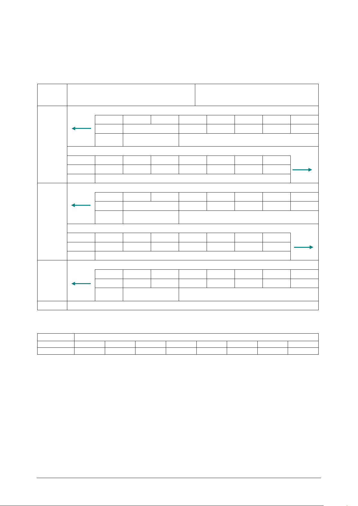
8.3.3 Sequence for reading the V.24 signal status
Bus
cycle
Bus master writes to
Bus master reads from
1.
The user program reads the idle code from the 1SI serial interface
Byte 0 1 2 3 4 5 6
7
00H
nnnnH
xxH
xxH
xxH
xxH
xxH
Ack.
job
Status
No meaning
The bus master writes the job for writing the V.24 signals
Byte 0 1 2 3 4 5 6
7
30H
xxH
xxH
xxH
xxH
xxH
xxH
xxH
Job
No meaning
2.
The user program reads the response from the 1SI serial interface
Byte 0 1 2 3 4 5 6
7
31H
nnnnH
xxH
xxH
xxH
xxH
xxH
Ack.
job
Signals*)
No meaning
The bus master writes the acknowledgment and accepts the sequence number.
Byte 0 1 2 3 4 5 6
7
31H
xxH
xxH
xxH
xxH
xxH
xxH
xxH
Job
No meaning
3.
After the first receive transaction is terminated, the 1SI serial interface returns to the idle state.
Byte 0 1 2 3 4 5 6
7
00H
nnnnH
xxH
xxH
xxH
xxH
xxH
xxH
Ack.
job
Status
No meaning
-
The bus master ends the job.
MSB
LSB
00 0 0 0 DCD
CTS
RTS
DSR
DTR
7 6 5 4 3 2 1 0
The table is an example of how the CPU reads the status of the V.24 signals from the 1SI
serial interface. The I/O memory is 8 bytes.
master
1SI serial interface
1SI serial interface
* Signal states
TB20 – Serial interface 1SI | Version 1| 13.03.2019 76
Page 77
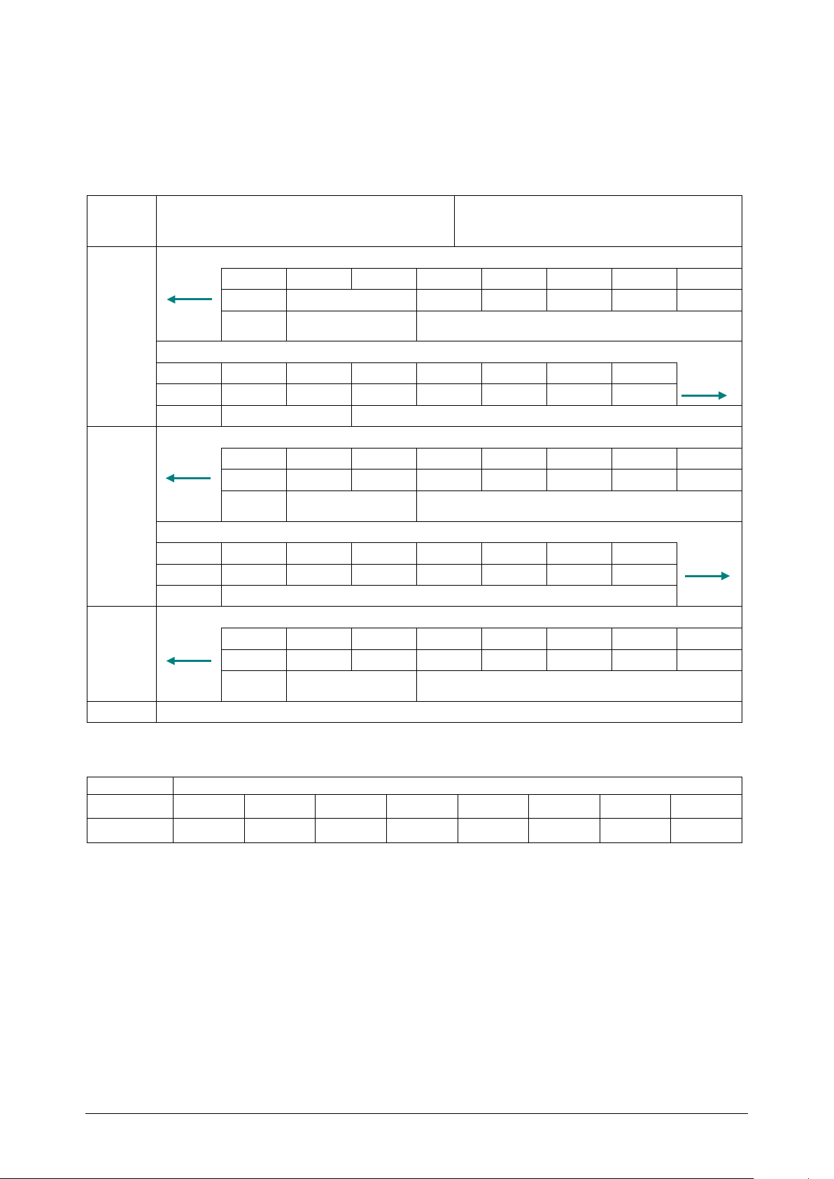
8.3.4 Sequence for writing V.24 signals
Bus
cycle
Bus master writes to
Bus master reads from
1.
The user program reads the idle code from the 1SI serial interface
Byte 0 1 2 3 4 5 6
7
00H
nnnnH
xxH
xxH
xxH
xxH
xxH
Ack.
job
Status
No meaning
The bus master writes the job for reading the V.24 signal status
Byte 0 1 2 3 4 5 6
7
10H
xxH
xxH
xxH
xxH
xxH
xxH
xxH
Job
Signal states*)
No meaning
2.
The user program reads the response from the 1SI serial interface
Byte 0 1 2 3 4 5 6
7
40H
nnnnH
xxH
xxH
xxH
xxH
xxH
xxH
Ack.
job
Status
No meaning
The bus master writes the idle state to the job byte
Byte 0 1 2 3 4 5 6
7
00H
xxH
xxH
xxH
xxH
xxH
xxH
xxH
Job
No meaning
3.
After the transaction is terminated, the 1SI serial interface returns to the idle state.
Byte 0 1 2 3 4 5 6
7
00H
nnnnH
xxH
xxH
xxH
xxH
xxH
xxH
Ack.
job
Status
No meaning
-
The bus master ends the job.
MSB
LSB
00 0 0 0 DCD
CTS
RTS
DSR
DTR
7 6 5 4 3 2 1 0
The table is an example of how the CPU writes V.24 signals to the 1SI serial interface. The
I/O memory is 8 bytes.
master
1SI serial interface
1SI serial interface
* Signal states
TB20 – Serial interface 1SI | Version 1| 13.03.2019 77
Page 78
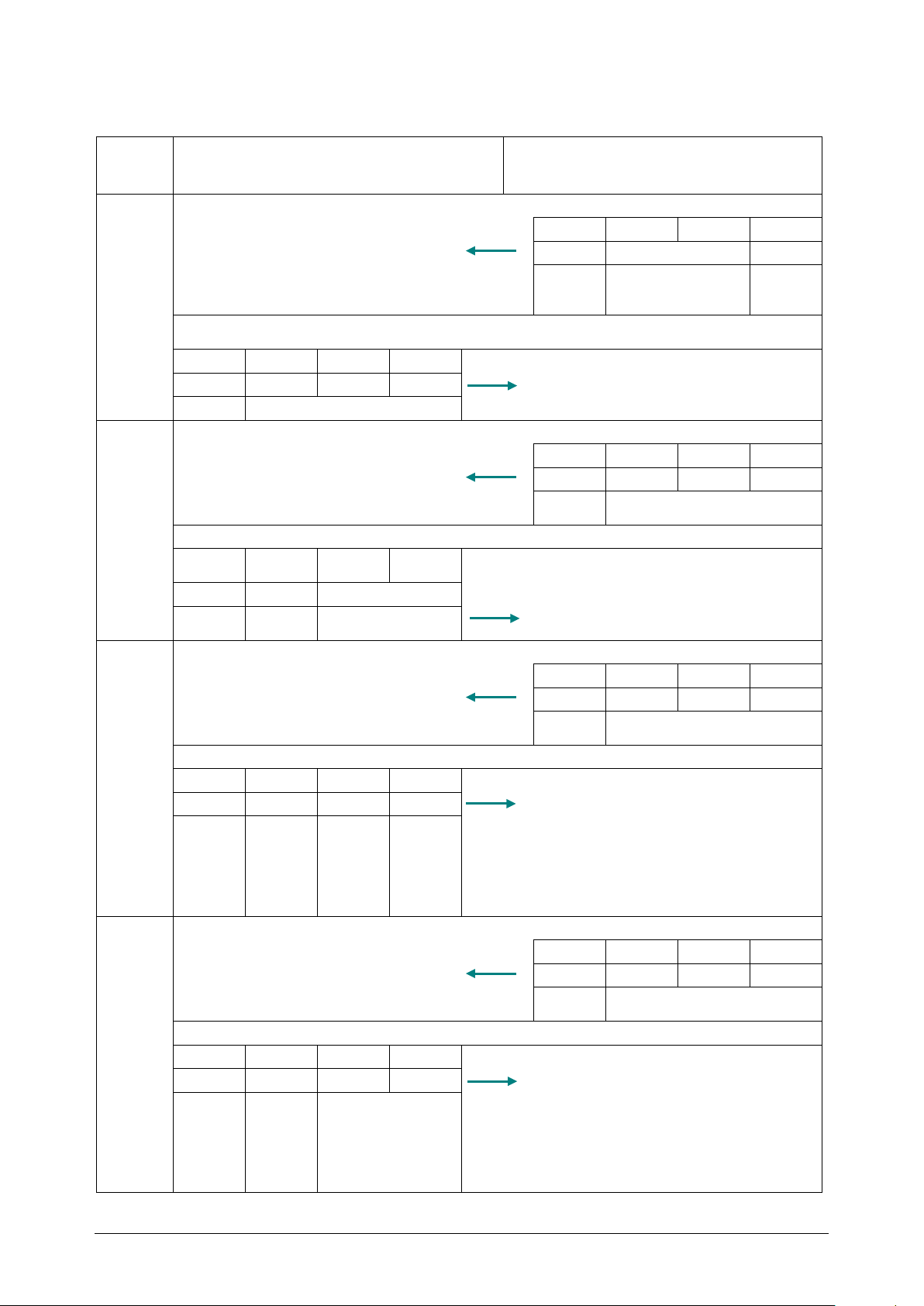
8.3.5 Example sequence for XON/XOFF
Bus
cycle
Bus master writes to
Bus master reads from
1.
User program reads the idle code
Byte 0 1 2
3
00H
nnnnH
xxH
Ack.
Status
No
g
Job:
Send parameter code (1 0 1 or 5H) plus sequence number 0
Byte 0 1 2
3
50H
xxH
xxH
xxH
Job
No meaning
2.
User program reads the response from the 1SI serial interface
Byte 0 1 2
3
50H
xxH
xxH
xxH
Ack.
job
No meaning
The job has been accepted, the CPU of the bus master sends the first segment
Byte 0 1 2
3
Job: Continue parameter and increment sequence
number
51H
20H
0004H
Data flow: Code for data flow parameter
Job
Data
flow
Transmission
length
3.
User program reads the response from the 1SI serial interface
Byte 0 1 2
3
51H
xxH
xxH
xxH
Ack.
job
No meaning
No error is displayed; the CPU of the bus master sends the second segment
Byte 0 1 2
3
52H
0BH
0DH
00H
Job
DC1
DC3
Waiting
4.
User program reads the response from the 1SI serial interface
Byte 0 1 2
3
52H
xxH
xxH
xxH
Ack.
job
No meaning
No error is displayed; the CPU of the bus master sends the third segment
Byte 0 1 2
3
53H
C8H
xxH
xxH
Job
Waiting
LSB
No meaning
master
1SI serial interface
1SI serial interface
job
meanin
time for
XON
after
XOFF -
MSB
time for
XON
after
XOFF -
TB20 – Serial interface 1SI | Version 1| 13.03.2019 78
Page 79
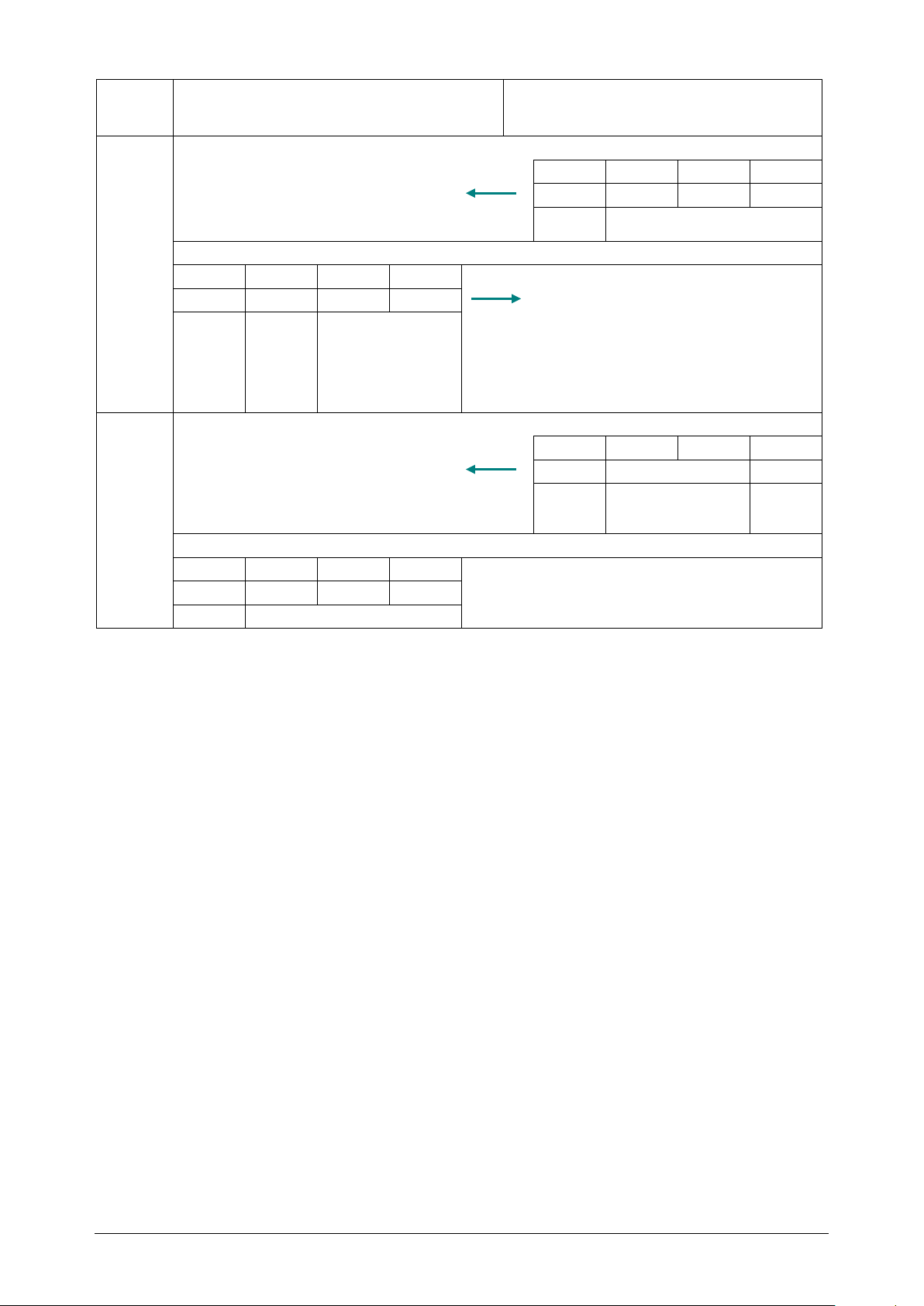
Bus
master
cycle
Bus master writes to
Bus master reads from
5.
User program reads the response from the 1SI serial interface
Byte 0 1 2
3
53H
xxH
xxH
xxH
Ack.
job
No meaning
Bus master repeats the third segment and waits for job end acknowledgment
Byte 0 1 2
3
53H
C8H
xxH
xxH
Job
Waiting
LSB
No meaning
6.
User program reads the response from the 1SI serial interface
Byte 0 1 2
3
73H
xxH
xxH
Ack.
Status
No
g
The CPU of the bus master writes the idle code to the job and terminates the job.
Byte 0 1 2
3
00H
xxH
xxH
xxH
Job
No meaning
1SI serial interface
time for
XON
after
XOFF -
1SI serial interface
job
meanin
TB20 – Serial interface 1SI | Version 1| 13.03.2019 79
Page 80

9 Error handling
Status word
(hexadecimal)
Error description
• The acknowledgment character (DLE) was received too early.
The serial interface module outputs an error as a response to the following conditions:
• If the send job is longer than 224 bytes, the 1SI serial interface responds with a job end
acknowledgment and the status word contains the error code. The bus master writes an
idle code to the job and terminates the job.
• If a receive job is sent to the 1SI serial interface and the received message contains an
error, the 1SI serial interface takes over the receive job code with the sequence number
zero and the status word contains the error code. The bus master writes an idle code to
the job and terminates the job.
• If a receive job is sent to the 1SI serial interface and there is no received message
available, the 1SI serial interface takes over the receive job code with the sequence
number zero and the status word contains the value 0101
condition, but it prevents the 1SI serial interface from being disabled in receive job
mode and waits for a receive message, so that transmission jobs can be executed. The
bus master writes an idle code to the job and terminates the job.
Table: Error codes in the status word
. This is not an error
H
0702 H Only 3964(R): Error while establishing connection
Following the transmission of STX, NAK or any character was received (except DLE or
STX).
0703 H Only 3964(R): Acknowledgment delay time (QVZ) exceeded
Following the transmission of STX, no response was received by the partner during
the acknowledgment delay time.
0704 H Only 3964(R): Cancellation by partner
One or more characters were received by the partner during running transmission
operation.
0705 H Only 3964(R): Negative acknowledgment during transmission
0706 H Only 3964(R): Error at end of connection
• The partner refused the frame at the end with NAK or any character (except
DLE).
or
0707 H
0708 H Only ASCII driver: CTS = ON or XON – waiting period expired.
070B H Only 3964(R): Initialization conflict can't be remedied
070C H Only 3964(R): Initialization conflict can't be remedied
Only 3964(R): Acknowledgment delay time at the connection end or response
monitoring time following transmission frame exceeded
No response from the partner after the clearing of the connection with DLE ETX
within the acknowledgment delay time.
Occurs when both parties are set to high priority.
Occurs when both parties are set to low priority.
TB20 – Serial interface 1SI | Version 1| 13.03.2019 80
Page 81

0802 H Only 3964(R): Error while establishing connection:
• The module receives an undefined character while the partner is switching on.
DLE was not received within the character delay time.
• Valid value range 1 to 224 bytes
• One or more characters were received (except NAK or STX) when not running.
or
• Following a received STX, additional characters were sent by the partner
without waiting for the DLE response.
Following mains power-ON of the partner:
0805 H Only 3964(R): Logic error during reception
Following reception of DLE, another character was received (except DLE or ETX).
0806 H Character delay time (ZVZ) exceeded
• Two consecutive characters were not received within the character delay time
or
Only for 3964(R):
• During the establishing of the connection, the 1st character after sending the
0807 H Only 3964(R): Frame length not permitted:
A frame with the length 0 was received (frame without payload data).
0808 H Only 3964(R): Error with block check character BCC:
The internally formed value of the BCC doesn't agree with the BCC received by the
partner at the connection end.
0809 H Only 3964(R): The number of repetitions must be set identically at the partner.
080A H The receive buffer is full
080C H An error occurred during transmission
• A transmission error (parity error, stop bit error, overflow error) was detected.
Only for 3964(R):
• Repetitions are begun when a transmission error occurs during transmission or
reception operations.
• When a disrupted character is received in the idle state, the error message
occurs immediately in order to promptly detect disruptive influences in the
transmission line.
0810 H Only ASCII driver: A parity error occurred
0811 H Only ASCII driver: A character frame error occurred
0812 H
0818 H Only ASCII driver: CTS or DSR were switch to Off within a transmission process.
0850 H
0B01 H The receive buffer has reached a level greater than 2/3rds.
1B41 H Number of bytes indicated at the parameter LEN of the FBs not permitted
Only ASCII driver: Additional characters were received after CTS was set to Off or
XOFF was sent.
The receive frame is greater than the parameterized length or greater than the
maximum allowed length.
TB20 – Serial interface 1SI | Version 1| 13.03.2019 81
Page 82

10 General technical specifications
Order no. 600-400-7BA31
Module type 1SI serial interface
Cable length (shielded)
RS232
RS422/485
Electrically isolated from backplane bus Yes
Power dissipation Max. 0.7 W
Power supply for modules 5 V DC, max. 130 mA
Certifications CE, UL pending
Noise immunity DIN EN 61000-6-2 “EMC Immunity”
Interference emission DIN EN 61000-6-4 “EMC Emission”
Vibration and shock resistance
Isolation voltage 500 V
Protection rating IP 20
Relative humidity 95% r H without condensation
Installation position Any
Permissible ambient temperature 0 °C to 60 °C
Transport and storage temperature -20 °C to 80 °C
Dimensions (H x W x D) 110 mm x 25 mm x 73 mm
Weight Approx. 120 g
Hot-pluggable Yes
max. 15 m
max. 1200 m
DIN EN 60068-2-8:2008 “Vibration” DIN EN
60068-27:2010 “Shock”
TB20 – Serial interface 1SI | Version 1| 13.03.2019 82
Page 83
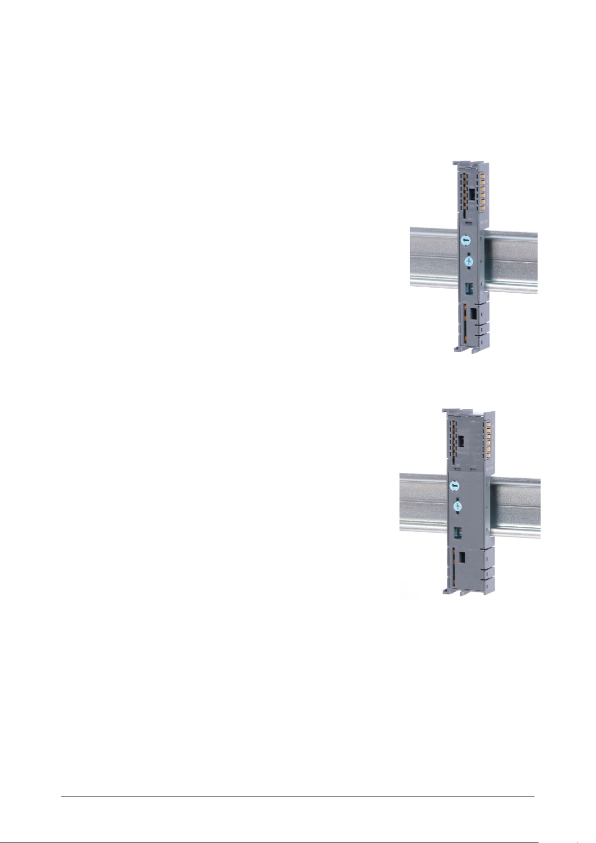
11 Spare parts
11.1 Base modules
11.1.1 14 mm width standard base module
The 14 mm standard base module is available in sets of five with
order no. 600-900-9AA01.
11.1.2 25 mm width base module
The 25 mm standard base module is available in sets of five
with order no. 600-900-9AA21.
TB20 – Serial interface 1SI | Version 1| 13.03.2019 83
Page 84
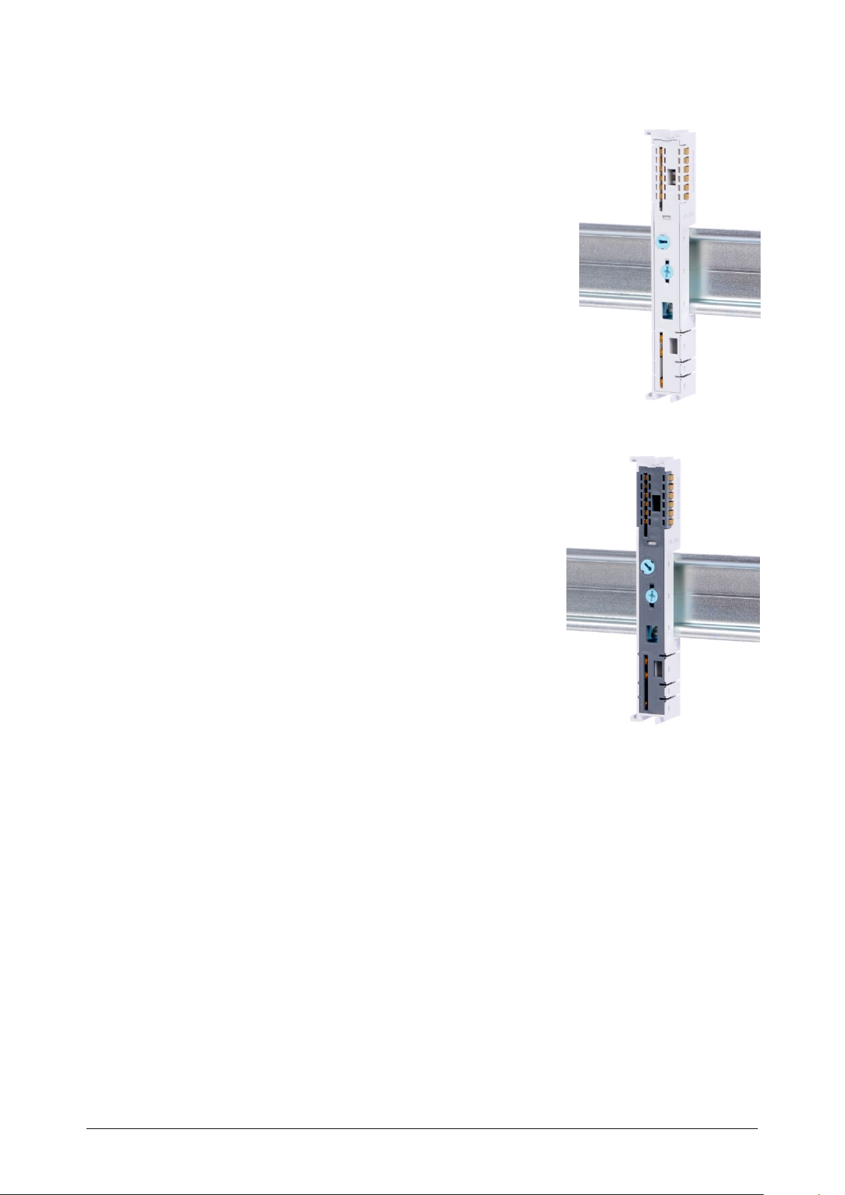
11.1.3 Power and isolation base module
The power and isolation base module is available in sets of
five with order no. 600-900-9BA01.
11.1.4 Power base module
The power base module is available in sets of five with order
no. 600-900-9CA01.
It can be used with the power module (600-700-0AA01) and
with all bus couplers.
TB20 – Serial interface 1SI | Version 1| 13.03.2019 84
Page 85
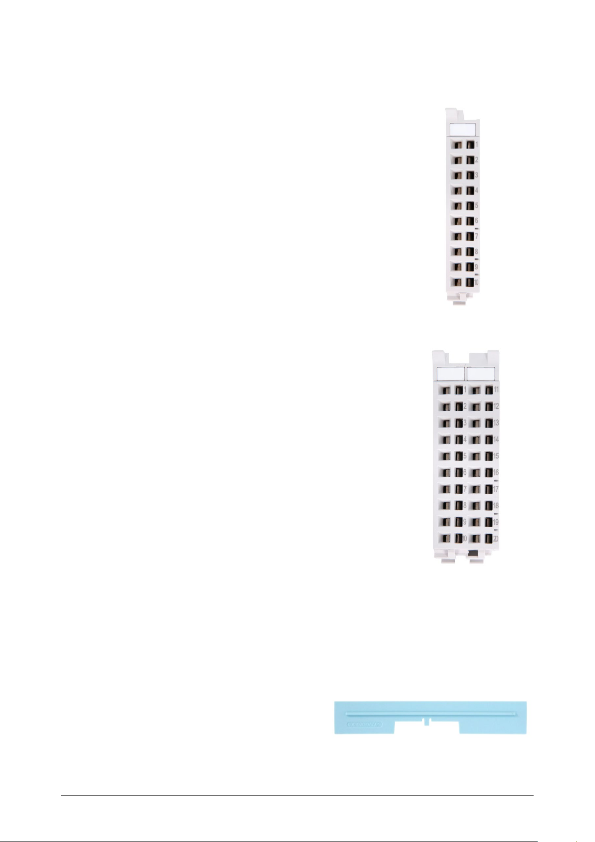
11.2 Front connectors
11.2.1 Front connector, 10-pin
The 10-terminal front connector is available in sets of five
with order no. 600-910-9AJ01.
11.2.2 Front connector, 20-pin
The 20-pin front connector is available in sets of five
with order no. 600-910-9AT21.
11.3 Electronic modules
Electronic modules can be ordered as spare parts with the order number of the original
product. Electronic modules are always sent as a complete assembly, including the
corresponding base module and front connector.
11.4 Final bus cover
The final bus cover is available in sets of five with order no. 600-920-9AA01.
TB20 – Serial interface 1SI | Version 1| 13.03.2019 85
 Loading...