

Page 1

Countertop Incubator
PC100-Pro
PC900-Pro
PC1200-Pro
Countertop Agitator
PF15-Pro
PF48-Pro
PF96-Pro
Platelet Storage Instructions for Use
and Operation Manual
Pro Line Incubator - Pro Line Agitator
360415/B
Page 2

Document History
Revision Date CO Supersession Revision Description
A 6 JAN 2020* 15008 n/a Initial release.
B 19 MAY 2020 15365 B supersedes A
* Date submitted for Change Order review. Actual release date may vary.
• Added detail regarding agitator speed to Enable or Disable Motion section.
• Updated Notied Body information in the Compliance section.
Document Updates
The document is furnished for information use only, is subject to change without notice and should not be construed as a
commitment by Helmer Scientic. Helmer Scientic assumes no responsibility or liability for any errors or inaccuracies that may
appear in the informational content contained in this material. For the purpose of clarity, Helmer Scientic considers only the most
recent revision of this document to be valid.
Notices and Disclaimers
Condential / Proprietary Notices
Use of any portion(s) of this document to copy, translate, disassemble or decompile, or create or attempt to create by reverse
engineering or otherwise replicate the information from Helmer Scientic products is expressly prohibited.
Copyright and Trademark
Helmer®, i.Series®, i.Center®, AgiTrak™, and Rel.i™ are registered trademarks or trademarks of Helmer, Inc. in the
United States of America. Copyright © 2020 Helmer, Inc. All other trademarks and registered trademarks are the property of their
respective owners.
Helmer, Inc., doing business as (DBA) Helmer Scientic and Helmer.
Disclaimer
This manual is intended as a guide to provide the operator with necessary instructions on the proper use and maintenance of
certain Helmer Scientic products.
Any failure to follow the instructions as described could result in impaired product function, injury to the operator or others, or void
applicable product warranties. Helmer Scientic accepts no responsibility or liability resulting from improper use or maintenance of
its products.
The screenshots and component images appearing in this guide are provided for illustrative purposes only, and may vary slightly
from the actual software screens and/or product components.
Helmer Scientic
14400 Bergen Boulevard
Noblesville, IN 46060 USA
www.helmerinc.com Part No. 360415/Rev B
Page 3

Helmer Scientic Pro Line Platelet Storage Instructions for Use
Contents
1 About this Manual ................................................................................................ 1
1.1 Intended Audience .......................................................................................... 1
1.2 Model Reference ............................................................................................1
1.3 Intended Use ...............................................................................................1
1.4 Safety Precautions and Symbols ...............................................................................1
1.5 Avoiding Injury ..............................................................................................2
1.6 General Recommendations ...................................................................................3
Platelet Incubator (stand-alone)
2 Installation ...................................................................................................... 4
2.1 Location ...................................................................................................4
2.2 Placement and Leveling ...................................................................................... 4
2.3 Chart Recorder .............................................................................................5
3 Pro Line Platelet Incubator Operation ................................................................................ 6
3.1 Initial Start-Up ..............................................................................................6
3.2 Operation .................................................................................................7
3.3 Users and Passwords ........................................................................................7
3.4 Change Temperature Setpoint .................................................................................8
3.5 Set Alarm Parameters ........................................................................................ 8
3.6 Active Alarms .............................................................................................. 9
3.7 Mute and Disable Active Alarms ................................................................................ 9
3.8 Min/Max Temperature Monitoring ............................................................................... 9
3.9 Electronic Access Control (Optional) ............................................................................ 10
Pro Line Platelet Agitator (stand-alone)
4 Installation ......................................................................................................11
4.1 Location ................................................................................................... 11
4.2 Power Connection ...........................................................................................11
4.3 Mounting Brackets ......................................................................................... 12
4.4 Placement, Leveling and Setup ...............................................................................12
4.5 Storage Conguration .......................................................................................12
4.6 Load the Platelet Agitator ....................................................................................13
5 Pro Line Platelet Agitator Operation ................................................................................ 14
5.1 Initial Start-Up .............................................................................................14
5.2 Motion Alarm .............................................................................................. 14
5.3 Motion Alarm Controls ....................................................................................... 14
5.4 Enable or Disable Motion ....................................................................................15
360415/B ii
Page 4

Helmer Scientic Pro Line Platelet Storage Instructions for Use
Pro Line Platelet Agitator (installed in Platelet Incubator)
6 Installation ..................................................................................................... 16
6.1 Location ..................................................................................................16
6.2 Storage Conguration .......................................................................................16
6.3 Power and Communication Connection ......................................................................... 17
6.4 Agitator Mounting Brackets ...................................................................................17
6.5 Placement and Leveling ..................................................................................... 18
6.6 Load the Platelet Agitator ....................................................................................18
7 Pro Line Platelet Agitator Operation ................................................................................19
7.1 Initial Start-Up .............................................................................................19
7.2 Motion Alarm .............................................................................................. 19
7.3 Motion Alarm Controls ....................................................................................... 19
7.4 Enable or Disable Motion ....................................................................................21
7.5 AgiTrak Setup and Information ................................................................................ 21
8 ProductSpecications ........................................................................................... 23
8.1 Operating Standards ........................................................................................23
9 Compliance .................................................................................................... 25
9.1 Safety Compliance .........................................................................................25
9.2 Environmental Compliance ...................................................................................25
9.3 Electromagnetic Compliance .................................................................................25
Appendix A: i.Series Active Alarms .................................................................................... 27
Appendix B: i.Series Application Icons ................................................................................. 28
360415/B iii
Page 5

Helmer Scientic Pro Line Platelet Storage Instructions for Use
1 About this Manual
1.1 Intended Audience
This manual provides information on how to use the Pro Line platelet incubator and platelet agitator. It is intended for use by end
users of the platelet incubator and platelet agitator and authorized service technicians.
1.2 Model Reference
This manual covers all Pro Line platelet incubators and platelet agitators which may be identied by size or model number.
1.3 Intended Use
Note
This equipment has been tested and found to comply with the limits for a Class A digital device, pursuant to part 15 of the
FCC Rules. These limits are designed to provide reasonable protection against harmful interference when the equipment
is operated in a commercial environment. This equipment generates, uses and can radiate radio frequency energy and, if
not installed and used in accordance with the instruction manual, may cause harmful interference to radio communications.
Operation of this equipment in a residential area is likely to cause harmful interference in which case the user will be required
to correct the interference at his own expense.
Helmer platelet incubators are intended to provide the controlled temperature environment required for the storage of platelet
products. Helmer platelet agitators are intended to provide controlled agitation required for the storage of platelet products.
The devices are intended to be operated by personnel who have procedures in place for meeting FDA, AABB, EU or any other
applicable regulations for the processing and storage of platelet products.
1.4 Safety Precautions and Symbols
Symbols found in this document
The following symbols are used in this manual to emphasize certain details for the user:
Task Indicates procedures which need to be followed.
Note Provides useful information regarding a procedure or operating technique when using Helmer
Scientic products.
NOTICE Advises the user against initiating an action or creating a situation which could result in damage to
equipment; personal injury is unlikely.
Symbols found on the units
The following symbols may be found on the incubator or agitator or incubator packaging or agitator packaging:
Caution: Risk of damage to equipment or
danger to operator
Refer to documentation
EU Authorized Representative
360415/B 1
Page 6

Helmer Scientic Pro Line Platelet Storage Instructions for Use
1.5 Avoiding Injury
Review safety instructions before installing, using, or maintaining the equipment.
Platelet Incubator Platelet Agitator
• Before moving unit, remove the installed agitator
(if applicable).
• Before moving unit, ensure door is closed.
• Before moving unit, disconnect the AC power cord and
secure the cord.
• When moving unit, use assistance from a second person.
• Never physically restrict any moving component.
• Avoid removing electrical service panels and access panels
unless so instructed.
• Do not store or place objects or liquid containers on top of
the incubator.
• Keep hands away from pinch points when closing the door or
when agitation motion is enabled (if applicable).
• Avoid sharp edges when working inside the
electrical compartment.
• Ensure biological materials are stored at recommended
temperatures determined by standards, literature, or good
laboratory practices.
• Proceed with caution when adding and removing product
from the platelet incubator.
• Use manufacturer supplied power cord only.
• Using the equipment in a manner not specied by Helmer
Scientic may impair the protection provided by
the equipment.
• The platelet incubator is not considered to be a storage
cabinet for ammable or hazardous materials.
• Before moving unit, remove contents from the drawers.
• Do not open multiple drawers at the same time.
• Before moving unit, disconnect the DC power cord and
secure the cord.
• When moving unit, use assistance from a second person.
• Never physically restrict any moving component.
• Avoid removing electrical service panels and access panels
unless so instructed.
• Keep hands away from pinch points when agitation motion
is enabled.
• Ensure both left and right side drawer stop panels are fully
installed prior to operating the agitator.
• Avoid sharp edges when working inside the
electrical compartment.
• Ensure biological materials are stored at recommended
temperatures determined by standards, literature, or good
laboratory practices.
• Proceed with caution when adding and removing products
from the platelet agitator.
• Use only manufacturer supplied power supply/cord when
operating stand-alone or within incubator.
• Using the equipment in a manner not specied by Helmer
Scientic may impair the protection provided by
the equipment.
• The platelet agitator is not considered to be a storage cabinet
for ammable or hazardous materials.
REQUIRED: Decontaminate parts prior to sending for service or repair. Contact Helmer or your distributor for decontamination
instructions and a Return Authorization Number.
360415/B 2
Page 7

Helmer Scientic Pro Line Platelet Storage Instructions for Use
1.6 General Recommendations
General Use
Platelet Incubator Platelet Agitator
Allow platelet incubator or platelet agitator to come to room
temperature before switching power on.
During initial startup, motion alarm may sound if the motion
is disabled. The low temperature alarm may sound while the
platelet incubator reaches operating temperature.
Initial Loading
After the platelet incubator reaches room temperature, allow chamber temperature to stabilize at the setpoint before storing product.
After the platelet agitator reaches room temperature, begin storing product.
Allow platelet agitator to come to room temperature before
switching power on.
During initial startup, motion alarm may sound if the motion is
disabled.
During initial startup for stand alone operation, device selection
of “X” is required for motion to occur.
360415/B 3
Page 8

Helmer Scientic Pro Line Platelet Storage Instructions for Use
Platelet Incubator (stand-alone)
2 Installation
2.1 Location
Note
Hot ambient temperatures with high humidity may cause condensation on the outside of the incubator.
♦ Has a sturdy, level surface.
♦ Has a grounded outlet meeting national electric code (NEC) and local electrical requirements.
♦ Is clear of direct sunlight, high temperature sources, and heating and air conditioning vents.
♦ Meets limits specied for ambient temperature (15 °C to 35 °C) and relative humidity.
♦ Minimum 24” (610 mm) above for ambient temperatures of 28 °C to 35 °C.
♦ Minimum 4” (102 mm) above for ambient temperatures of 15 °C to 28 °C.
♦ Minimum 12” (305 mm) behind for ambient temperatures of 28 °C to 35 °C.
♦ Minimum 4” (102 mm) behind for ambient temperatures of 15 °C to 28 °C.
2.2 Placement and Leveling
• The product should not be used adjacent to other equipment. If adjacent use is necessary, the product should be
observed to verify normal operation in the conguration in which it will be used.
• The use of accessories other than those specied for the product by Helmer is not recommended. They may result in
increased emissions or decreased immunity of the device.
• Refer to the Electromagnetic Compliance section for additional information.
Notes
• Ensure the AC power and backup battery power are turned o on the incubator prior to connecting an agitator.
• Rear stand-o brackets are provided with the platelet incubator and should be installed prior to placing the incubator
in its location.
1. Align keyhole openings in stand-o bracket with screws on back of incubator and slide down to engage.
2. Tighten screws using a #2 Phillips screwdriver to secure.
3. Place platelet incubator on sturdy surface.
4. Ensure platelet incubator is level
360415/B 4
Page 9

Helmer Scientic Pro Line Platelet Storage Instructions for Use
2.3 Chart Recorder
Note
For complete information, refer to the Temperature Chart Recorder Operation and Service Manual.
A B F
C
D
E
Chart recorder with paper and battery installed.
Table 1. Chart Recorder
Label Description Function
A Left and Right Arrow buttons Adjust settings and stylus position.
B LED Indicates status of chart recorder in operating mode, or selected temperature range in paper change mode.
C Chart change button Adjust position of stylus when changing chart paper, or run a test pattern.
D Stylus Mark temperature line on paper.
E Reset button Restart chart recorder.
F Backup battery Provides power during AC power failure. Connect prior to use.
Install / Replace Chart Paper
Note
For accurate temperature reading, ensure the current time is aligned with the time line groove when the chart knob
is fully tightened.
1. Press and hold C button. When stylus begins to move left, release button. The LED ashes.
2. When stylus stops moving, remove chart knob then move knob up and away.
3. Place chart paper on chart recorder.
4. Gently lift stylus and rotate paper so current time line corresponds to time line groove.
5. Hold chart paper in place while making sure the chart knob is fully tightened. (Failure to fully tighten the
knob can result in paper slipping and losing time.)
6. Press and hold C button. When stylus begins to move right, release button.
7. Conrm stylus is marking on paper and stops at the correct temperature.
8. Calibrate chart recorder to match primary temperature if needed and close recorder door.
Stylus and
time line groove
360415/B 5
Page 10

Helmer Scientic Pro Line Platelet Storage Instructions for Use
3 Pro Line Platelet Incubator Operation
3.1 Initial Start-Up
1. Plug the power cord into a grounded outlet meeting the electrical requirements on the product specication label.
2. Turn the AC power switch ON.
3. Turn the backup battery switch ON.
4. The Start screen is displayed.
Start screen
The language screen is displayed when the i.C3 is powered on. Use the Language screen to select the i.C3 display language.
Language screens
Note
English is the default language.
If an alarm sounds, temporarily mute the alarm by touching the Mute button.
Home screen Mute icon
Note
Active alarms are displayed on the Home screen. If an alarm condition other than High T
service manual for troubleshooting.
emperature occurs, refer to the
360415/B 6
Page 11

Helmer Scientic Pro Line Platelet Storage Instructions for Use
3.2 Operation
Notes
• Refer to the i.C3 User Guide for complete information regarding the i.C3 User Interface.
• The i.C³ Home screen displays temperature and alarm information, and provides icons to gain access to other functions
of the i.C³.
• After two minutes of inactivity, the screensaver will be displayed. To return to the Home screen, touch the screensaver.
Home screen Home screensaver (touch to return to Home screen)
3.3 Users and Passwords
The Users and Passwords screen provides a way for the administrator-level user to limit access to certain screens. The
administrator-level password can be changed by selecting Change Password. The
choosing the Access Setup button from the Users and Passwords screen as well as from the Access Log screen.
Access Control Setup screen can be opened by
> Enter settings password. Select Users and Passwords.
Users and Passwords screen Change Password keypad
Note
Default Settings password is 1234
Change Password
1. Select the Change Password button. A numeric keypad is displayed.
2. Enter a unique 4-digit code and select the √. A numeric keypad appears
3. Re-enter the 4-digit code to conrm and select the √.
4. Select the Back arrow icon to return to the previous screen or the Home icon to return to the Home screen.
360415/B 7
Page 12

Helmer Scientic Pro Line Platelet Storage Instructions for Use
3.4 Change Temperature Setpoint
> Enter Settings password. Select Temperature Setpoints. Touch minus (-) or plus (+) on spin box to change value.
Settings screen
Notes
• Default Settings password is 1234.
• Default setpoint is 22.0 °C.
3.5 Set Alarm Parameters
> Enter Settings password. Select Alarm Settings. Touch minus (-) or plus (+) on spin box to set each alarm parameter.
Settings screen
Alarm Settings screens
Alarm settings control the circumstances and timing of alarm condition indicators displayed on the i.C3 Home screen.
360415/B 8
Page 13

Helmer Scientic Pro Line Platelet Storage Instructions for Use
3.6 Active Alarms
Active alarms are displayed on the Home screen. Refer to Appendix A for a list of potential active alarms.
Home screen with active alarm
Notes
• When the door switch is bypassed, the incubator and door open alarm continue to operate as if the door is closed.
• The door switch may be bypassed by opening the door and pulling the switch cylinder.
• The number of agitators, internal and external fans, and heat pumps will vary based on incubator model.
• Fan failure alarm may occur if facility power is lost.
3.7 Mute and Disable Active Alarms
Audible alarms may be temporarily muted by touching the Mute icon. The delay duration can be set and changed by selecting
Sound Settings from the Settings screen. The duration may be set to any value from 1 - 60 minutes. The delay time remaining
will be displayed in the bottom right corner of the icon. If the alarm is still active after the mute delay has ended, the audible alarm
will sound.
Unmuted Muted
> Enter the Settings password. Scroll down to select Sound Settings. Touch minus (-) or plus (+) on spin box to set the mute
duration.
3.8 Min/Max Temperature Monitoring
The Min/Max temperature display provides the highest and lowest Primary Monitor probe temperature reading since the last
system reset (power-on event) or manually-initiated reset. Touch the Reset icon to the right of the display to manually reset.
Notes
• The Min/Max temperature display can be turned on or o through Display Settings.
• Once the time reaches the maximum display of 999 hours and 60 minutes, the message will display “>999:60”, but
minimum and maximum temperatures will continue to be tracked.
360415/B 9
Page 14

Helmer Scientic Pro Line Platelet Storage Instructions for Use
3.9 Electronic Access Control (Optional)
Allows user-specic secure access to the incubator. The Access Control Setup screen can be opened from the Access Log screen
or by choosing the Access Setup button from the Users and Passwords screen.
Notes
• During a power failure, the optional Access Control lock will remain locked. It can be unlocked using backup battery
power until battery power is depleted or until the backup battery
• Switching the back-up battery key switch OFF will disable the monitoring system during a power failure.
• During a power failure, use the mechanical door key to provide secure storage for incubator contents.
• Refer to i.C3 User Guide for complete information regarding Access Control.
Setup
Congure and manage user-specic accounts to allow controlled access to the incubator.
switch is switched OFF.
Access Control Setup password screen Access Control Setup screen
Enter the supervisor PIN to set up Access Control and follow the on-screen prompts to set up users.
Notes
• Initial factory supervisor PIN is 5625
• The supervisor PIN cannot be deleted, and should be changed to prevent unauthorized user ID setup. The supervisor
PIN does not allow access to the unit. At least one user ID must be set up to gain access to the unit.
Open Incubator with Access Control
Access Control Home screen
Enter a valid PIN using the keypad.
360415/B 10
Page 15

Helmer Scientic Pro Line Platelet Storage Instructions for Use
Pro Line Platelet Agitator (stand-alone)
4 Installation
4.1 Location
• The product should not be used adjacent to other equipment. If adjacent use is necessary, the product should be
observed to verify normal operation in the conguration in which it will be used.
• The use of accessories other than those specied for the product by Helmer is not recommended. They may result in
increased emissions or decreased immunity of the device.
• Refer to the Electromagnetic Compliance section for additional information.
Note
Add 1.5” (38 mm) to the agitator width to accommodate the trolley frame when agitation motion is enabled.
♦ To ensure continuous operation of linearly shifting loads, the location surface must be level and adequately accommodate the full
weight of the agitator when loaded with product.
♦ Has a grounded outlet meeting the electrical requirements listed on the product specication label.
♦ Is clear of direct sunlight, high temperature sources, and heating and air conditioning vents.
♦ Minimum 0.5” (13 mm) behind.
♦ Minimum 0.75” (20 mm) on left and right sides.
♦ Meets limits specied for ambient temperature (15˚C to 35˚C) and relative humidity.
4.2 Power Connection
Note
Use only the optional Helmer AC/DC power supply for stand-alone conguration.
The platelet agitator may be used in a stand-alone conguration. A power supply with adaptable plugs is available for stand-alone use.
Select and install the desired plug prior to attaching the power supply to the agitator. The power supply is not used when congured
inside a Pro Line platelet incubator.
CongureandAttachPowerSupply
1. Remove the cover plate by using the thumb to push and hold the spring loaded locking key downward while sliding the
plate forward. Retain the cover plate in secure location for future use.
2. Select the desired plug and slide in place until it locks (a clicking sound will occur).Make sure the plug is rmly attached.
3. Attach the power supply to the platelet agitator, and ensure the rotating lock is nger tight prior to plugging power supply
into facility AC.
360415/B 11
Page 16

Helmer Scientic Pro Line Platelet Storage Instructions for Use
4.3 Mounting Brackets
Mounting brackets are included and may be installed for use inside the incubator or in stand-alone conguration.
Install Mounting Brackets
1. Carefully place the agitator on its back on a solid surface allowing access to the bottom of the unit.
2. Locate the two nutserts in the right or left side toward the front of the unit and align with the two holes in the
mounting bracket.
3. Hand thread the screws through each hole, and secure using a #2 Phillips screwdriver.
4. Repeat steps 2 and 3 for the opposite side.
5. Return the agitator to the upright position.
6. Carefully place the agitator in the desired location aligning the hole in each bracket with the holes in the mounting surface.
7. Hand thread the screws through the bracket and into the mounting surface. Secure using a #2 Phillips screwdriver.
4.4 Placement, Leveling and Setup
NOTICE
• To prevent damage to the platelet agitator, lift using the ends of the base. Do not use the platelet agitator storage frame,
trolley or trolley drawer to lift agitator. If the platelet agitator base is not accessible, lift using the ends of the storage frame.
• The platelet agitator communication switch is fragile, do not use excessive force when changing the setting.
1. Place platelet agitator on sturdy surface.
2. Ensure platelet agitator is level.
3. Using a small athead screwdriver, turn the communication switch to the X position. Ensure the
arrow (shown in red for visibility in the adjacent picture) is pointing to the X.
4.5 StorageConguration
Drawers can be removed or moved to create additional storage space. Label holders are available and may be installed on
drawers.
To avoid injury, ensure both left and right side drawer stop panels are fully installed prior to operating the agitator.
Thumb Screws
Remove and Replace Drawers
1. Remove the thumb screws securing the drawer stop panels to the left and right sides of
the agitator. (Note the orientation of each panel)
2. Carefully pull each panel from the agitator and set panels and thumb screws aside.
3. Slide the drawer(s) out and remove.
4. Reinstall drawer in desired location by aligning the outer edges of the drawer with the slots in
the drawer guides and push inward.
5. Reinstall the drawer stop panels in the same orientation as removed, and secure with thumb
screws ensuring they are nger tight.
Install Label Holders (optional)
1. Insert the tabs on the label holder into the slots on the drawer.
2. Pivot the holder around the drawer handle and align the hole on the label holder with the corresponding hole on the drawer.
3. Push thumb screw through the hole in the label holder and through the hole in the drawer to secure.
360415/B 12
Page 17

Helmer Scientic Pro Line Platelet Storage Instructions for Use
4.6 Load the Platelet Agitator
Table 2. Agitator Capacity
Model
PF15-Pro 15 (2 per drawer; 3 per shelf) 7 (1 per drawer/shelf)
PF48-Pro 48 (6 per drawer/shelf) 16 (2 per drawer/shelf)
PF96-Pro 96 (12 per drawer/shelf) 32 (4 per drawer/shelf)
PF15-Pro
NOTICE
When opening drawer, grasp the center of the handle (not label holder). Open one drawer at a time.
Open the drawer to be loaded and lay the platelet bags at. The top of the storage frame may also be used for bag storage. Avoid
stacking bags. Maintain enough space around each bag for air circulation. For thicker bags, remove and/or adjust drawers. Place
the bag tubing under or around the bag.
Capacity
WBD/Random Bags SDP/Apheresis Bags
360415/B 13
Page 18

Helmer Scientic Pro Line Platelet Storage Instructions for Use
5 Pro Line Platelet Agitator Operation
5.1 Initial Start-Up
Use only rechargeable 9V NiMH batteries (1 included) for backup power to the motion alarm.
Notes
• Backup battery may need charging for 24 to 48 hours prior to use. Charging occurs when system is on facility power.
• Turning the alarm ON/OFF switch ON turns the motion alarm on and further allows the backup battery to recharge.
When in the OFF position, the Alarm is not activated and the battery will not recharge.
1. Plug the power supply cord into a grounded outlet that meets the electrical requirements on the product
specication label.
2. Switch the alarm ON/OFF switch ON.
3. Select alarm volume and alarm delay settings.
4. Set the communication switch to “X” when in stand-alone conguration using a small athead screwdriver.
5. Switch power ON/OFF switch ON.
5.2 Motion Alarm
♦ Enable the motion alarm when using the platelet agitator. The red LED will illuminate.
♦ Disable the motion alarm when not using the platelet agitator. Lack of motion triggers the alarm.
5.3 Motion Alarm Controls
Motion alarm switch. Alarm volume and delay controls
When platelet agitator motion stops the motion alarm is activated. The alarm condition is communicated as follows:
♦ Red alarm LED on motion alarm switch ashes.
♦ Audible alarm buzzer sounds when in stand-alone mode, the motion alarm switch is turned on, adjustable alarm delay time has
been exceeded, and volume has been turned up.
♦ Through a dry (no voltage) connection to an external monitoring device (if connected).
♦ Through a 9V connection to an external monitoring device (if connected).
Enable and Disable Motion Alarm
1. Switch the motion alarm ON/OFF switch ON.
2. Set volume to desired level.
3. Switch the motion alarm ON/OFF switch OFF.
NOTICE
If motion stops while the motion alarm is switched OFF, communication of the alarm (visual, audible, and signals to
external devices) is suppressed.
360415/B 14
Page 19

Helmer Scientic Pro Line Platelet Storage Instructions for Use
Alarm Delay
The duration of time between when agitation stops and when the alarm sounds is the alarm delay.
alarm delay control.
Notes
• The minimum alarm delay that can be set is approximately 10 seconds.
• Maximum alarm delay is approximately 10 minutes.
• The default motion alarm delay is set at the halfway point (approximately 4 to 5 minutes).
Set Alarm Delay
1. Using a small at-head screwdriver, rotate the control to the left (counterclockwise) to shorten the motion alarm delay.
2. Using a small at-head screwdriver, rotate the control to the right (clockwise) to extend the motion alarm delay.
Alarm Volume
The motion alarm volume has a variable setting.
Notes
• Rotating the volume control fully counter-clockwise will silence the audible alarm. If the motion alarm switch is turned
ON, the LED will blink providing a visual alarm when the agitator is in an alarm condition.
• Alarm volume is applicable only when the agitator alarm switch is in the ON position and the platelet agitator is in
stand-alone mode, or when communication is lost when congured in a platelet incubator.
The alarm delay is set using the
Set Alarm Volume
Rotate the motion alarm dial to the appropriate position for the desired volume level.
5.4 Enable or Disable Motion
Agitation switch. Agitator Speed Control
Notes
• The agitator speed is factory set to 72 CPM (as displayed in green) and is applicable when used in
stand-alone operation.
• For a setpoint of 72 CPM, rotate the arrow into the center of the green zone. The green zone represents an expanded
72 CPM area. Any point to the right of the green zone is a setpoint greater than 72 CPM.
• Contact Helmer Technical Service for instructions regarding Agitator Speed Verication (T3I468).
• For a platelet agitator in stand-alone conguration, switching the agitation ON/OFF switch ON will start the
agitation motion.
• For a platelet agitator in stand-alone conguration or installed in a platelet incubator, switching the agitation ON/OFF
switch OFF will stop the agitation motion.
Start/Stop Agitation
1. Select the desired speed from 40 to 80 CPM.
2. Load items into the platelet agitator.
3. Switch the agitation ON/OFF switch ON to begin movement.
4. Switch the motion alarm switch ON/OFF switch ON.
5. Switch the motion alarm switch ON/OFF switch OFF.
6. Switch the agitation ON/OFF switch OFF to stop movement.
7. Remove items from the platelet agitator.
360415/B 15
Page 20

Helmer Scientic Pro Line Platelet Storage Instructions for Use
Pro Line Platelet Agitator (installed in Platelet Incubator)
6 Installation
6.1 Location
Notes
• Only Helmer Pro Line platelet agitator may be used with Pro Line platelet incubator.
• Hot ambient temperatures with high humidity may cause condensation on the outside of the incubator.
• When placing a Pro Line agitator in the PC900-Pro or PC1200-Pro, ensure agitator placement allows the roll-top door
to open.
• Add 1.5” (38 mm) to the agitator width to accommodate the trolley frame when agitation motion is enabled.
To ensure continuous operation of linearly shifting loads, the location surface must be level and adequately accommodate the full
weight of the incubator with installed agitator when loaded with product.
6.2 StorageConguration
Drawers can be removed or moved to create additional storage space. Label holders are available and may be installed on
drawers.
To avoid injury, ensure both left and right side drawer stop panels are fully installed prior to operating the agitator.
Thumb Screws
Remove and Replace Drawers
1. Remove the thumb screws securing the drawer stop panels to the left and right sides of
the agitator. (Note the orientation of each panel)
2. Carefully pull each panel from the agitator and set panels and thumb screws aside.
3. Slide the drawer(s) out and remove.
4. Reinstall drawer in desired location by aligning the outer edges of the drawer with the slots in
the drawer guides and push inward.
5. Reinstall the drawer stop panels in the same orientation as removed, and secure with thumb
screws ensuring they are nger tight.
Install Label Holders (optional)
1. Insert the tabs on the label holder into the slots on the drawer.
2. Pivot the holder around the drawer handle and align the hole on the label holder with the corresponding hole on the drawer.
3. Push thumb screw through the hole in the label holder and through the hole in the drawer to secure.
360415/B 16
Page 21

Helmer Scientic Pro Line Platelet Storage Instructions for Use
6.3 Power and Communication Connection
Notes
• Use only the DC power cord supplied with the incubator when conguring the agitator within the incubator.
• Ensure the angled end of the DC power cord is attached to the agitator.
• Ensure AC power and backup battery power are turned OFF prior to connecting a Pro Line agitator to a
Pro Line incubator.
The Pro Line platelet agitator may be installed in a Pro Line platelet incubator.
Connect the data cable and DC power cable supplied with the incubator prior to placing the agitator inside the incubator.
DC Power Cable Communication Cable
Attach Power and Communication cables
1. Attach the DC power cable to the platelet agitator, ensuring the elbowed end is attached to the agitator and the rotating
locks at each end are nger tight.
2. Insert the communication cable in the data cable port.
6.4 Agitator Mounting Brackets
Mounting brackets are included and may be installed for use inside the incubator or in stand-alone conguration.
Install Mounting Brackets
1. Carefully place the agitator on its back on a solid surface allowing access to the bottom of the unit.
2. Locate the two nutserts in the right or left side toward the front of the unit and align with the two holes in the
mounting bracket.
3. Hand thread the screws through each hole, and secure using a #2 Phillips screwdriver.
4. Repeat steps 2 and 3 for the opposite side.
5. Return the agitator to the upright position.
6. Remove screws in the oor of the incubator prior to installing the agitator.
7. Carefully place the agitator inside an incubator,
8. Hand thread the screws through the bracket and into the holes in the oor of the incubator. Secure using a
#2 Phillips screwdriver.
360415/B 17
Page 22

Helmer Scientic Pro Line Platelet Storage Instructions for Use
6.5 Placement and Leveling
• The product should not be used adjacent to other equipment. If adjacent use is necessary, the product should be
observed to verify normal operation in the conguration in which it will be used.
• The use of accessories other than those specied for the product by Helmer is not recommended. They may result in
increased emissions or decreased immunity of the device.
• Refer to the Electromagnetic Compliance section for additional information.
NOTICE
• To prevent damage to the platelet agitator, lift using the ends of the base. Do not use the platelet agitator storage frame,
trolley or trolley drawer to lift agitator. If the platelet agitator base is not accessible, lift using the ends of the storage frame.
• The platelet agitator communication switch is fragile, do not use excessive force when changing the setting.
Notes
• Only Helmer Pro Line platelet agitators may be used with Pro Line platelet incubators.
• Ensure the AC power and backup battery power are turned o on the incubator prior to connecting an agitator.
• Ensure data cable is carefully positioned to the right of the agitator to prevent damage caused by agitation motion.
• The communication switch is fragile, do not use excessive force when changing the setting.
• To ensure continuous operation of linearly shifting loads, the location surface must adequately accommodate the full
weight of the incubator and agitator when loaded with product.
• Incubator restraining brackets are recommended when congured with an agitator operating at a setpoint speed greater
than 75 CPM, or when placed on a slick surface.
1. Using a small athead screwdriver, turn the communication switch to the 1 position. Ensure the
arrow (shown in red for visibility in the adjacent picture) is pointing to the 1.
2. Connect the data cable and DC power cable supplied with the incubator prior to placing the
agitator inside the incubator.
3. Place platelet agitator inside platelet incubator.
4. Ensure platelet agitator is level.
6.6 Load the Platelet Agitator
Table 3. Agitator Capacity
Model
PF15-Pro 15 (2 per drawer; 3 per shelf) 7 (1 per drawer/shelf)
PF48-Pro 48 (6 per drawer/shelf) 16 (2 per drawer/shelf)
PF96-Pro 96 (12 per drawer/shelf) 32 (4 per drawer/shelf)
PF48-Pro agitator with platelet bags (shown in a Helmer PC900-Pro incubator).
NOTICE
When opening drawer, grasp the center of the handle (not label holder). Open one drawer at a time.
Capacity
WBD/Random Bags SDP/Apheresis Bags
Open the drawer to be loaded and lay the platelet bags at. The top of the storage frame may also be used for bag storage. Avoid
stacking bags. Maintain enough space around each bag for air circulation. For thicker bags, remove and/or adjust drawers. Place
the bag tubing under or around the bag.
360415/B 18
Page 23

Helmer Scientic Pro Line Platelet Storage Instructions for Use
7 Pro Line Platelet Agitator Operation
When a platelet agitator is installed in a platelet incubator, power is supplied to the agitator through a dedicated DC power cord.
Motion data is transmitted between the platelet agitator and platelet incubator through the data cable. The platelet incubator
interprets the motion data and provides information regarding the status and state of the agitator.
7.1 Initial Start-Up
Notes
• Only Helmer Pro Line platelet agitator models may be used with Pro Line platelet incubator models.
• Refer to platelet agitator service manual for more information regarding installation of a platelet agitator in a
platelet incubator.
• Ensure data cable is carefully positioned to right of agitator to prevent damage caused by agitation motion.
• Use only manufacturer supplied DC power cord when conguring platelet agitator in platelet incubator.
• Ensure power switch and alarm switch are switched OFF prior to connecting agitator power cord to incubator.
• Ensure agitator communication switch is set to 1.
1. Switch alarm ON/OFF switch ON.
2. Select alarm volume and alarm delay settings.
3. Switch power ON/OFF switch ON.
7.2 Motion Alarm
When installing the Pro Line platelet agitator in a Pro Line platelet incubator, the motion alarm on the agitator will be suppressed
when the agitator is in communication with the incubator. The incubator generates its own motion alarm, based on its own alarm
delay period. If the agitation motion alarm switch is enabled, the motion alarm on the platelet agitator will sound only if motion has
stopped and communication to the incubator has been lost.
Notes
• Helmer recommends the motion alarm ON/OFF switch remain in the ON position.
• Motion information is transmitted through the data cable to the platelet incubator, even when the agitator motion alarm
is disabled.
• The platelet incubator interprets the motion information and generates its own motion alarm, based on its own alarm
delay period.
• Once the agitator has been connected to the incubator, communication will be interrupted, and the incubator will alarm,
if the agitator power switch is turned OFF.
• With the alarm enabled, the agitator alarm will time out and sound if power to the incubator is turned o for a duration
greater than the motion delay.
• In the event of a communication failure with the incubator, the agitator alarm will only become active (audible and visual)
if the agitator alarm switch is turned ON.
7.3 Motion Alarm Controls
LED
Motion alarm switch. Alarm volume and delay controls
When platelet agitator motion stops the motion alarm is activated. The alarm condition is communicated as follows:
♦ Red alarm LED on motion alarm switch ashes.
♦ Through a dry (no voltage) connection to an external monitoring device (if connected).
♦ Through a 9V, 100mA connection to an external monitoring device (if connected).
♦ Through a data cable to the Pro Line Platelet incubator causing an alarm condition to appear on the display and an audible
alarm to sound.
360415/B 19
Page 24

Helmer Scientic Pro Line Platelet Storage Instructions for Use
Enable and Disable Motion Alarm
1. Switch the motion alarm ON/OFF switch ON.
2. Set volume to desired level.
3. Switch the motion alarm ON/OFF switch OFF.
NOTICE
If motion stops while the motion alarm is switched OFF, communication of the alarm (visual, audible, and signals to other
external devices) is suppressed.
Alarm Delay
The duration of time between when agitation stops and when the alarm sounds is the alarm delay.
alarm delay control.
Notes
• The minimum alarm delay that can be set on the platelet agitator is approximately 10 seconds.
• Maximum alarm delay on the platelet agitator is approximately 10 minutes.
• The default motion alarm delay on the platelet agitator is set at the halfway point (approximately 4 to 5 minutes).
Set Alarm Delay
1. Using a small at-head screwdriver, rotate the control to the left (counterclockwise) to shorten the motion alarm delay.
2. Using a small at-head screwdriver, rotate the control to the right (clockwise) to extend the motion alarm delay.
The alarm delay is set using the
Alarm Volume
The motion alarm volume has a variable setting.
Notes
• Rotating the volume control fully counter-clockwise will silence the audible alarm. If the motion alarm switch is turned
ON, the LED will blink providing a visual alarm when the agitator is in an alarm condition.
• Alarm volume is applicable only when the agitator alarm switch is in the ON position and the platelet agitator is in
stand-alone mode, or when communication is lost when congured in a platelet incubator.
Set Alarm Volume
Rotate the motion alarm dial to the appropriate position for the desired volume level.
360415/B 20
Page 25

Helmer Scientic Pro Line Platelet Storage Instructions for Use
7.4 Enable or Disable Motion
Agitation switch. Communication switch
Notes
• For a platelet agitator in stand-alone conguration or installed in a platelet incubator, switching the agitation ON/OFF
switch OFF will stop the agitation motion.
• For a platelet agitator installed in a platelet incubator, the communication switch must be switched to 1. If the
communication switch is set to X, the agitator will not start/stop based on the platelet incubator door position.
The door switch on Helmer platelet incubators controls whether the installed platelet agitator is turned on or o. When the incubator
door is opened, agitation motion is paused. When the incubator door is closed, agitation motion is resumed.
Start / Stop Agitation
1. Open the platelet incubator door. Agitation motion stops.
2. Load items into the platelet agitator.
3. Close the platelet incubator door. Agitation motion resumes.
4. Open the platelet incubator door. The platelet agitator motion stops.
5. Remove items from the platelet agitator.
6. Close the platelet incubator door.
7.5 AgiTrak Setup and Information
Note
Agitation speed is set through the AgiTrak system when an agitator is congured inside an incubator. This setting
overrides the setting on the agitator speed control.
Select the AgiTrak icon to open the AgiTrak Setup and Info screen. Enter the agitator information to allow monitoring and control of
the device.
AgiTrak Setup and Info screen Agitator Setup screen
360415/B 21
Page 26

Helmer Scientic Pro Line Platelet Storage Instructions for Use
Note
Default Setup password is 1234.
Setup Agitator(s)
1. From the Home screen, select the AgiTrak icon .
2. Select Agitator Setup button. A numeric keypad appears.
3. Enter the Agitator Setup password. The Agitator Setup screen appears.
4. Enter agitator information for each agitator installed.
5. Select the Back arrow to return to the previous screen or the Home icon to return to the Home screen.
360415/B 22
Page 27
Helmer Scientic Pro Line Platelet Storage Instructions for Use
8 ProductSpecications
8.1 Operating Standards
These units are designed to operate under the following environmental conditions:
Platelet Incubator Platelet Agitator
♦ Indoor use only
♦ Altitude (maximum): 2000 m
♦ Ambient temperature range: 15 °C to 35 °C
♦ Relative humidity (maximum for ambient temperature): 80%
for temperatures up to 31 °C, decreasing linearly to 45% at
35 °C
♦ Internal temperature control range: 20 °C to 35 °C
♦ Overvoltage category: II
♦ Pollution degree: 2
♦ Sound level is less than 70 dB(A) under normal operation
Notes
• Power Draw and Power Consumption specications include internally operating Pro Line agitator supplied from the
Pro Line incubator through a 24 VDC umbilical cable (DC power cord).
• Pro Line agitator Power draw is measured in full-load Amperes during stand-alone operation and includes
power supply.
• Pro Line incubator Power Draw measured in Watts.
• 100 V Pro Line incubator models have only 1 circuit breaker.
♦ Indoor use only
♦ Altitude (maximum): 2000 m
♦ Ambient temperature range: 15 °C to 35 °C
♦ Relative humidity (maximum for ambient temperature): 80%
for temperatures up to 31 °C, decreasing linearly to 45% at
35 °C
♦ Overvoltage category: I
♦ Pollution degree: 2
♦ Sound level is less than 60 dB(A).
♦ Mains supply voltage: ±10% of nominal voltage
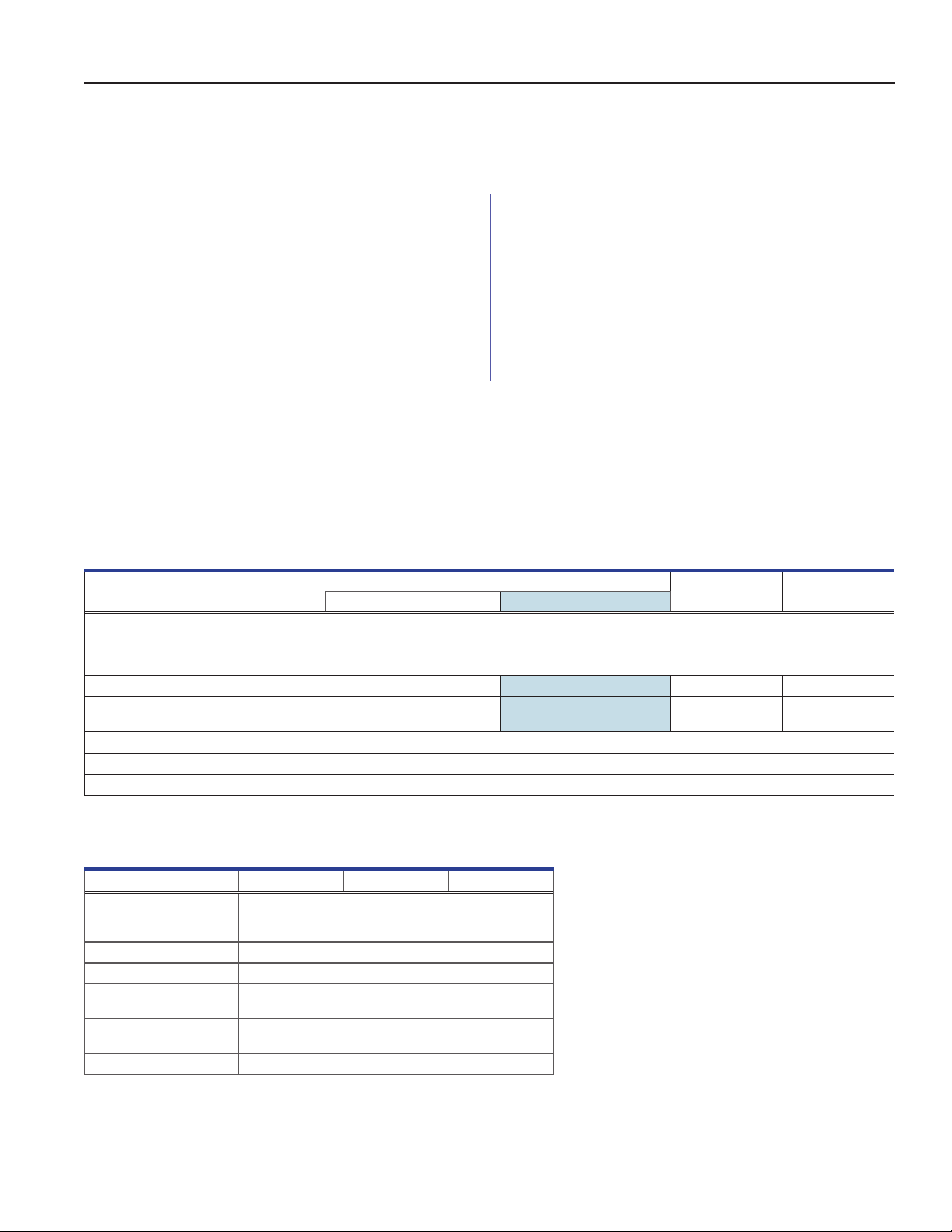
Table4.ProLinePlateletIncubatorElectricalSpecications
PC100-Pro PC900-Pro PC1200-Pro
monitor battery backup (12V) w/ full system battery backup
Input Voltage and Frequency 100-240VAC, 50 Hz/60 Hz
Voltage Tolerance ±10%
Circuit Breakers 7.0A quantity 2 (100V units - quantity 1)
Agitator Power Draw (if installed) 16 W at 24V (DC) 16 W at 24V (DC) 16 W at 24V (DC) 16 W at 24V (DC)
Incubator Power Consumption
(with agitator installed)
Power Source Varies (refer to product specication label)
Remote Alarm Capacity 1A at 33V (AC) RMS or 30V (DC)
Internal Outlet Maximum Current Draw 1.5A AT 24V (DC)
* 22°C in 24°C ambient static operation
** Pull down (full power)
65 Watts*
352 Watts**
75 Watts*
415 Watts**
65 Watts*
352 Watts**
65 Watts*
352 Watts**
Notes
Table5.ProLinePlateletAgitatorElectricalSpecications
PF15-Pro PF48-Pro PF96-Pro
Input Voltage and
Frequency
Voltage Tolerance ±10% (AC input to power supply)
Power Draw
Power Source
Agitation Speed
(cycles / minute)
Remote Alarm Capacity 1A at 33V (AC) RMS or 70V (DC)
Stand-alone (power supply): 100-240VAC, 50/60 Hz
Agitator Unit: 24VDC
< 16 Watts nominal
24VDC AC/DC power supply (stand-alone)
24VDC umbilical cable (congured with incubator)
40-80 CPM
• The interface on the remote alarm monitoring
system is intended for connection to the end
user’s central alarm system(s) that uses
normally-open or normally-closed dry contacts.
• Platelet Incubator: If an external power supply
exceeding 33V (RMS) or 30V (DC) is connected
to the remote alarm monitoring system’s circuit,
the remote alarm will not function properly; may
be damaged; or may result in injury to the user.
• Platelet Agitator: If an external power supply
exceeding 33V (RMS) or 70V (DC) is
connected to the remote alarm monitoring
system’s circuit, the remote alarm will not
function properly; may be damaged; or may
result in injury to the user.
360415/B 23
Page 28

Helmer Scientic Pro Line Platelet Storage Instructions for Use
Table6. ProLinePlateletStorageSpecications
PC100-Pro PC900-Pro PC1200-Pro PF15-Pro PF48-Pro PF96-Pro
Height 27.2” (689 mm) 30.4” (772 mm) 30.4” (772 mm) 13.5” (343 mm) 14.9” (379 mm) 14.9” (379 mm)
Width 20.8” (528 mm) 26.0” (661 mm) 40.3 (1023 mm) 16.0” (407 mm) 17.8” (453 mm) 32.8” (834 mm)
Depth 22.3” (565 mm) 30.2” (766 mm) 30.2” (766 mm) 9.1” (232 mm) 14.9” (379 mm) 14.9” (379 mm)
Weight 116 lbs (53 kg) 136 lbs (62 kg) 173 lbs (79 kg)
33 lbs (15 kg) 50 lbs (23 kg) 80 lbs (37 kg)
Note
Add 1.25” (31.75 mm) to depth of the PC100-Pro for handle.
360415/B 24
Page 29
Helmer Scientic Pro Line Platelet Storage Instructions for Use
9 Compliance
9.1 Safety Compliance
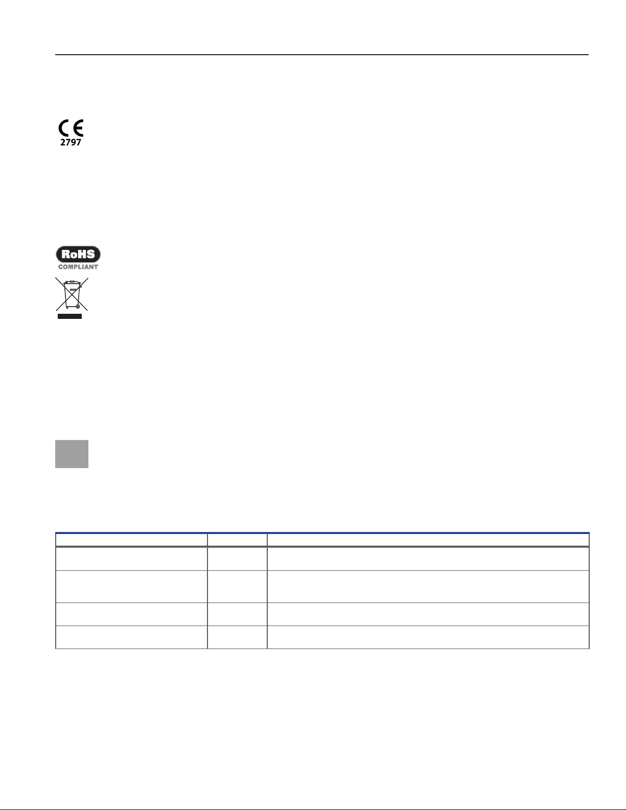
This device complies with the requirements of directive 93/42/EEC concerning Medical Devices, as amended
by 2007/47/EC.
This product is certied to applicable UL and CSA standards by a NRTL.
This product is IECEE CB Scheme certied and complies with national dierences for safety certication beyond
IEC 61010-1-12 3rd edition.
9.2 Environmental Compliance
This device complies with the 2011/65/EU Directive for the Restriction of Hazardous Substances (RoHS).
This device falls under the scope of Directive 2012/19/EU Waste Electrical and Electronic Equipment (WEEE) .
When disposing of this product in countries aected by this directive:
♦ Do not dispose of this product as unsorted municipal waste.
♦ Collect this product separately.
♦ Use the collection and return systems available locally.
For more information on the return, recovery, or recycling of this product, contact your local distributor.
9.3 Electromagnetic Compliance
This device complies with FCC Radiated and Conducted Emissions Approval to CFR47, Part 15; Class A levels
This product is intended for use in the electromagnetic environment specied below.
should assure the product is used in such an environment.
Electromagnetic Emissions
Emissions Test Compliance Electromagnetic Environment - Guidance
RF emissions CISPR 11 Group 1 The product uses RF energy only for its internal function. Therefore, its RF emissions are very
RF emissions CISPR 11 Class A The product is suitable for use in all establishments other than domestic and those directly
Harmonic Emissions
IEC 61000-3-2
Voltage Fluctuations/Flicker Emissions
IEC 61000-3-3
Class A
Complies
low and are not likely to cause any interference in nearby electronic equipment.
connected to the public low-voltage power supply network that supplies buildings used for
domestic purposes.
• The product should not be used adjacent to other equipment. If adjacent use is necessary, the product should be
observed to verify normal operation in the conguration in which it will be used.
• The use of accessories other than those specied for the product by Helmer is not recommended. They may result in
increased emissions or decreased immunity of the device.
The customer or the user of the product
360415/B 25
Page 30
Helmer Scientic Pro Line Platelet Storage Instructions for Use
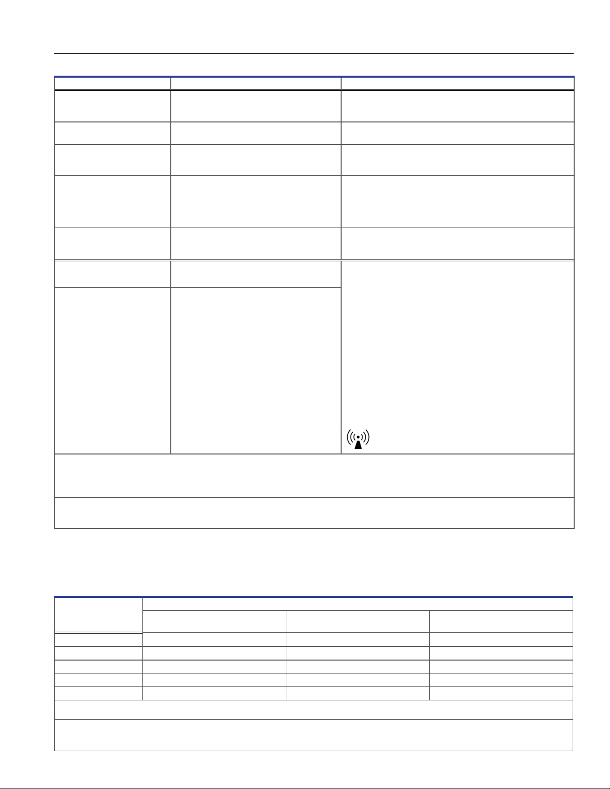
Electromagnetic Immunity
Immunity Test Compliance Level Electromagnetic Environment - Guidance
Electrostatic discharge
(ESD) IEC 61000-4-2
Electrical fast transient/burst
IEC 61000-4-4
Surge
IEC 61000-4-5
Voltage dips and interruptions
IEC 61000-4-11
Power frequency
(50/60Hz) magnetic eld
IEC 61000-4-8
Conducted RF
IEC 61000-4-6
Radiated RF
IEC 61000-4-3
±8 kV contact
±15 kV air
Floors should be wood, concrete or ceramic tile. If oors are
covered with synthetic material, the relative humidity should be at
least 30%
±2 kV
±1 kV for I/O lines
±1 kV dierential mode for AC
±2 kV common mode for AC
Mains power quality should be that of a typical commercial or
hospital environment.
Mains power quality should be that of a typical commercial or
hospital environment.
±1 kV common mode async for I/O lines
100% drop, 0.5 cycle, 6 times each
90°, 135°, 180°, 225°, 270°, 315°)
(@ 0°, 45°,
100% drop, 250 cycles, 6 times (@ 0°)
30% dip, 25 cycles, 6 times (@ 0°)
Mains power quality should be that of a typical commercial or
hospital environment.
If the user of the product requires continued operation during power
mains interruptions, it is recommended that the product be powered
from an uninterruptible power source.
30 A/m Power frequency magnetic elds should be at levels characteristic
of a typical location in a typical commercial or hospital environment.
3 V
rms
150 kHz to 80MHz
3 V/m to 28 V/m at frequencies
up to 5.785 GHz
Portable and mobile RF communications equipment should be
used no closer to any part of the product, including cables, than the
recommended separation distance calculated from the equation
applicable to the frequency of the transmitter
Recommended separation distance:
d = 1.2√P
d = 1.2√P
for 80 MHz to 800 MHz
d = 2.3√P
for 800 MHz to 5.7 GHz
where P is the maximum output power rating of the transmitter in
Watt (W) according to the transmitter manufacturer and d is the
recommended separation distance in meters (m).
Field strengths from xed RF transmitters, as determined by an
electromagnetic site surveya, should be less than the compliance
levelb in each frequency range.
Interference may occur in the vicinity of equipment
marked with this symbol.
a
Field strengths from xed transmitters, such as base stations for radio (cellular/cordless) telephones and land mobile radios, amateur radio, AM and FM radio broadcast and TV broadcast
cannot be predicted theoretically with accuracy. To assess the electromagnetic environment due to xed RF transmitters, an electromagnetic site survey should be considered, if the measured
eld strength in the location in which the product is used exceeds the applicable RF compliance level above, the product should be observed. If abnormal operation is observed, additional
measures may be necessary such as reorienting or relocating the product.
b
Over the frequency range 150 kHz to 80 MHz, eld strengths should be less than 3 V/m.
Notes
• At 80MHz and 800MHz, the higher frequency range applies
• These guidelines may not apply in all situations. Electromagnetic propagation is aected by absorption and reection from structures, objects, people and animals.
Recommended Separation Distances
This product is intended for use in an electromagnetic environment in which radiated RF disturbances are controlled. The customer
or the user of the product can help prevent electromagnetic interference by maintaining a minimum distance between portable and
mobile RF communications equipment (transmitters) and the product – according to the maximum output power and frequency of
the communications equipment – as recommended in the following table.
Rated maximum output
power of transmitter in
watts (W)
150 kHz to 80 MHz
0.01 0.12 0.12 0.23
0.1 0.38 0.38 0.73
1 1.2 1.2 2.3
10 3.8 3.8 7.3
100 12 12 23
For transmitters rated at a maximum output power not listed above, the recommended separation distance d in meters (m) can be estimated using the equation applicable to the frequency of the
transmitter, where P is the maximum output power rating of the transmitter in watts (W) according to the transmitter manufacturer.
Notes
• At 80MHz and 800MHz, the higher frequency range applies
• These guidelines may not apply in all situations. Electromagnetic propagation is aected by absorption and reection from structures, objects, people and animals.
Separation distance according to the frequency of transmitter in meters (m)
80 kHz to 800 MHz
d=1.2√P
d=1.2√P
800 kHz to 5.7 GHz
d=2.3√P
360415/B 26
Page 31

Helmer Scientic Pro Line Platelet Storage Instructions for Use
Appendix A: i.Series Active Alarms
Alarm Description
Primary Monitor Probe High Temp Primary monitor probe reading is above high temperature alarm setpoint
Primary Monitor Probe Low Temp Primary monitor probe reading is below low temperature alarm setpoint
Primary Monitor Probe Failure Primary monitor probe is not functioning properly
Control Probe Failure Control probe is not functioning properly
Agitator 1 Communication Failure Agitator 1 not installed; communication cable not installed; Agitator On/O switch turned OFF
Agitator 1 High Speed Agitator 1 speed (CPM) is above high speed alarm setpoint
Agitator 1 Low Speed Agitator 1 speed (CPM) is below low speed alarm setpoint
Agitator 1 Maintenance Required Check and replace trolley support wheels
Condensate Tray Full Rear condensate tray is full
External Fan 1 Failure External Fan 1 is not functioning properly
External Fan 2 Failure External Fan 2 is not functioning properly
Internal Fan 1 Failure Internal Fan 1 is not functioning properly
Heat Pump 1 High Temp Heat Pump 1 probe reading is above high temperature alarm setpoint
Heat Pump 1 Connection Error Temperature is moving away from setpoint
Heat Pump 1 Failure Heat Pump 1 is not functioning properly
Drive Space is Low SD card is near capacity
Drive Space is Full SD card is full, no history being recorded
Power Failure Power to unit has been disrupted
Door Open (time) Door is open beyond user-specied duration
Low Battery Rechargeable battery voltage is low
No Battery Battery is not connected
MPB Communication Failure Communication is lost with heat pump controls
Communication Failure Messages 1, 2, 3 1 Communication lost between i.C
2 Communication lost between i.C3 display board and internal system memory
3 Corrupt database
(recommendation is to empty soon to avoid overow)
3
display board and control board
360415/B 27
Page 32
Helmer Scientic Pro Line Platelet Storage Instructions for Use
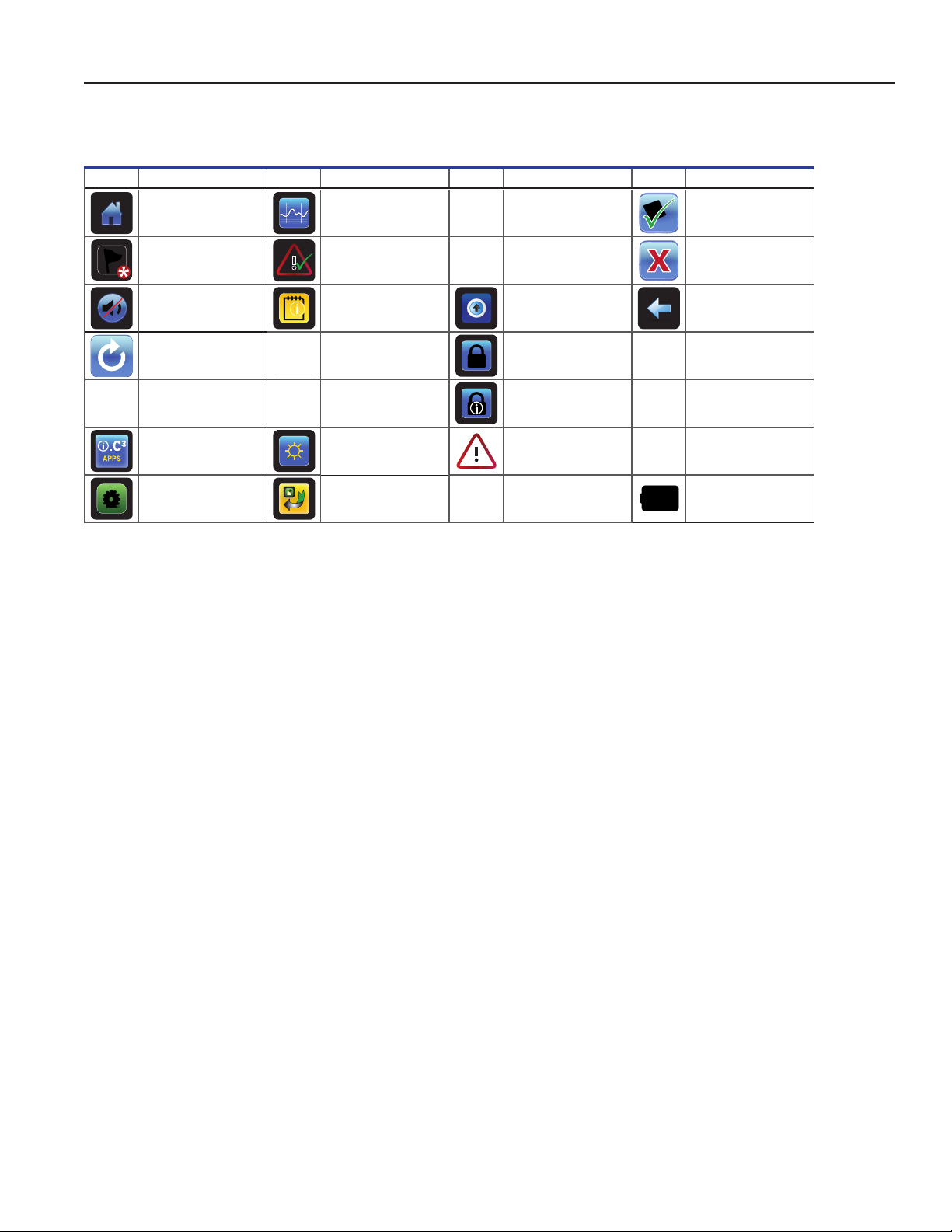
Appendix B: i.Series Application Icons
Icon
Description
Home Temperature Graph CSV Download Save
Event Log Alarm Test PDF Download Cancel
Mute Information Logs Upload Back Arrow
Reset AgiTrak Access Control Scroll
Zoom Information
i.C³ Applications Display Brightness Alarm Conditions Zoom Out
Settings Icon Transfer Cancel Test Battery Power
Icon
Description
Contact Information/
Contact Helmer
Icon
Description Icon Description
Access Log
Temperature Graph
Forward/Back
360415/B 28
Page 33

Helmer Scientic
14400 Bergen Boulevard, Noblesville, IN 46060 USA
Copyright © 2020 Helmer, Inc.
360415/B
 Loading...