

Page 1

Labratory Refrigerator
iLR105-GX, iLR113-GX, iLR120-GX,
iLR125-GX, iLR245-GX, iLR256-GX
Blood Bank Refrigerator
iBR105-GX, iBR113-GX, iBR120-GX,
iBR125-GX, iBR245-GX, iBR256-GX
Pharmacy Refrigerator
iPR105-GX, iPR113-GX, iPR120-GX,
iPR125-GX, iPR245-GX, iPR256-GX
i.C³® User Guide
For Helmer i.Series® Refrigerators
360405/B
Page 2

i.C3 User Guide
Document History
Revision Date CO Supersession Revision Description
A 6 JAN 2019 14212 n/a Initial release.
B 21 AUG 2019 14892 B supersedes A Updated cover page to reference all GX i.Series model refrigerators
* Date submitted for change order review. Actual release date may vary.
Document Updates
This document is furnished for information use only, is subject to change without notice and should not be construed as a commitment
by Helmer Scientic. Helmer Scientic assumes no responsibility or liability for any errors or inaccuracies that may appear in the
informational content contained in this material. For the purpose of clarity, Helmer Scientic considers only the most recent revision of
this document to be valid.
Support Informaon
Operation and Service Manuals provide additional product information. Manuals are available at http://info.helmerinc.com/manuals.
Noces and Disclaimers
The i.C³® User Guide provides information about use of the i.C³. Refer to the product operation or service manual for general
information. Refer to the product service manual for additional information about the equipment on which the i.C³ is installed.
The i.C³
applicable program in source code format, please contact:
utilizes open source components. For a list of the specic open source programs, their associated licenses and copies of the
®
Helmer Scientic
14400 Bergen Blvd.
Noblesville, Indiana 46060 USA
317.773.9073
[email protected]
Copyright and Trademark
Helmer®, i.Series®, and i.C³® are trademarks or registered trademarks of Helmer, Inc. in the United States of America.
Helmer, Inc., doing business as (DBA) Helmer Scientic and Helmer.
Condenal / Proprietary Noces
Use of any portion(s) of this document to copy, translate, disassemble or decompile, or create or attempt to create by reverse
engineering or otherwise the information from Helmer Scientic products is expressly prohibited.
Disclaimer
This manual is intended as a guide to provide the operator with necessary instructions on the proper use and maintenance of certain
Helmer Scientic products.
Any failure to follow the instructions as described could result in impaired product function, injury to the operator or others, or void
applicable product warranties. Helmer Scientic accepts no responsibility for liability resulting from improper use or maintenance of
its products.
The screenshots and component images appearing in this guide are provided for illustrative purposes only, and may vary slightly from
the actual software screens and/or product components.
i
360405/B
Page 3

i.C3 User Guide
Contents
1 Overview ...........................................................................................4
Features
Using the Touchscreen
Care of the i.C
2 Initial Setup .........................................................................................6
Language Conguration
Settings Conguration
3 Home Screen Basics ................................................................................. 7
Home Screen Layout
Home Screen Icons and Indicators
4 i.C3 Applications (APPS) .............................................................................. 8
Using i.C3 Applications .................................................................................8
5 Temperature Alarm T est ..............................................................................10
6 Min/Max Temperature Monitoring ...................................................................... 11
7 Temperature Graph ................................................................................. 12
Event Data
Viewable with the 1-Day Time Span ......................................................................13
............................................................................................4
.................................................................................5
3
Screen .................................................................................5
................................................................................6
.................................................................................6
..................................................................................7
.......................................................................7
.........................................................................................13
8 Information Logs ................................................................................... 15
Event Log
Event Log Detail Screen. . . . . . . . . . . . . . . . . . . . . . . . . . . . . . . . . . . . . . . . . . . . . . . . . . . . . . . . . . . . . . . . . . . . . . . . . . . . . . . 17
Access Control Log (if installed)
9 Data Transfer ......................................................................................19
CSV Download
Downloading Temperature Graphs and Alarm Event Data to PDF
Uploading Firmware Updates ...........................................................................22
10 Customizing the i.C3 Screen ..........................................................................24
Brightness Settings
Home Page Screensaver
11 i.C3 Settings ....................................................................................... 25
Password Protection of the i.C3 Settings Screen ............................................................25
Temperature Setpoint
Device Control Settings
Alarm Settings
Users and Passwords
Sound Settings ......................................................................................29
Display Settings
Light Control Settings
Device Status and History
Sensor Calibration
Date/Time ..........................................................................................32
..........................................................................................15
.........................................................................18
......................................................................................19
..............................................21
..................................................................................24
..............................................................................24
.................................................................................26
...............................................................................26
......................................................................................27
................................................................................28
.....................................................................................30
.................................................................................31
.............................................................................31
...................................................................................32
ii
360405/B
Page 4

i.C3 User Guide
Auxiliary Systems ....................................................................................33
Restore Factory Settings .............................................................................. 33
System Functions ....................................................................................34
12 Access Control (if installed) ...........................................................................35
Access Control Setup .................................................................................35
Access Control Screen ................................................................................36
Access Control as the Home Screen .....................................................................37
13 Icon Transfer .......................................................................................38
Appendix A - Icon Reference Guide ........................................................................ 39
Common Buttons ....................................................................................39
Application Icons ....................................................................................40
Appendix B - i.C3 Reference Guide ........................................................................ 41
General Settings. . . . . . . . . . . . . . . . . . . . . . . . . . . . . . . . . . . . . . . . . . . . . . . . . . . . . . . . . . . . . . . . . . . . . . . . . . . . . . . . . . . . . 41
Alarm Settings ......................................................................................43
Event Log Codes .................................................................................... 44
iii
360405/B
Page 5

1 Overview
CAUTION
• To avoid injury, before using the i.C3 User Information Center, read all instructions in the associated product
operation manual.
• To avoid damage to the i.C3 unit, read all instructions provided in this user guide.
Features
3
i.C
i.C3 User Guide
User Guide
The i.C
3
consists of an intuitive user interface and icon-driven touchscreen. The touchscreen is contained within the
®
instrument bezel, as are additional features.
Touchscreen
The interface to the i.C3 system.
USB Port
Connect a ash memory device to download temperature data or upload rmware.
Ethernet/RJ45 Connection (Not shown)
Allows the system to provide and receive data or commands to and from external devices.
Audio Speaker
Provides an audible signal when alarm conditions are met. Also provides audible signal when screen icons and buttons
are touched.
Touchscreen
4
USB Port
Audio Speaker
(boom of bezel)
360405/B
Page 6

3
i.C
i.C3 User Guide
User Guide
Using the Touchscreen
The touchscreen and touch techniques make the i.C3 easy to use. Icons, status indicators,and navigation buttons let the
user see and respond to i.C3 system conditions and events.
Note
Anything that touches the screen is understood as a command. Do not let anything touch the screen unintentionally.
Touch Techniques
Touch-select Touch once to select an item.
Touch-drag To move an item, touch-hold to select the item and drag it to a new location. Use a deliberate
touch-drag motion (without lifting)
Touch-scroll To scroll, slide nger slowly across the screen (horizontal or vertical). Stop before lifting. For
more control while scrolling, keep your nger in contact with the screen.
Icons, Indicators, and Buttons
For a complete list of all icons and indicators, see the Icon Reference Guide at the end of this user guide.
Application icons serve as navigation buttons to the associated application screen.
Status indicators alert the user to a change of status.
Navigation buttons return the display the previous screen or the Home screen.
Care of the i.C3 Screen
CAUTION
The iC3 screen uses a sensitive touch technology.
• To avoid damage to the touchscreen, do not apply pressure on the front of the display bezel or around the
screen borders.
• To preserve optimal touch sensitivity, keep the screen clean of foreign objects. Avoid excessive dust accumulation on
the screen.
• Do not expose the i.C
• Clean the i.C3 screen with a clean, dry cotton cloth.
3
screen to liquids or a harsh environment that contains excessive dust, heat or humidity.
5
360405/B
Page 7

3
i.C
i.C3 User Guide
User Guide
2 Initial Setup
Language Conguration
The Language screen is displayed when the i.C3 is powered on. Use the Language screen to select the i.C3 display
language.
Choose language
1. Touch the Language button. The language drop-down list is displayed.
2. Touch the language to be displayed. The selected language is displayed in the Language button.
3. Touch to conrm language selection, or to cancel.
4. Touch the Home icon to continue to the Home screen.
Note
English is the default language. Available languages may vary from those shown above.
Settings Conguration
Basic conguration parameters have been set for the i.C
refer to i.C3 Settings.
3
at the factory. If factory default settings need to be adjusted,
6
360405/B
Page 8
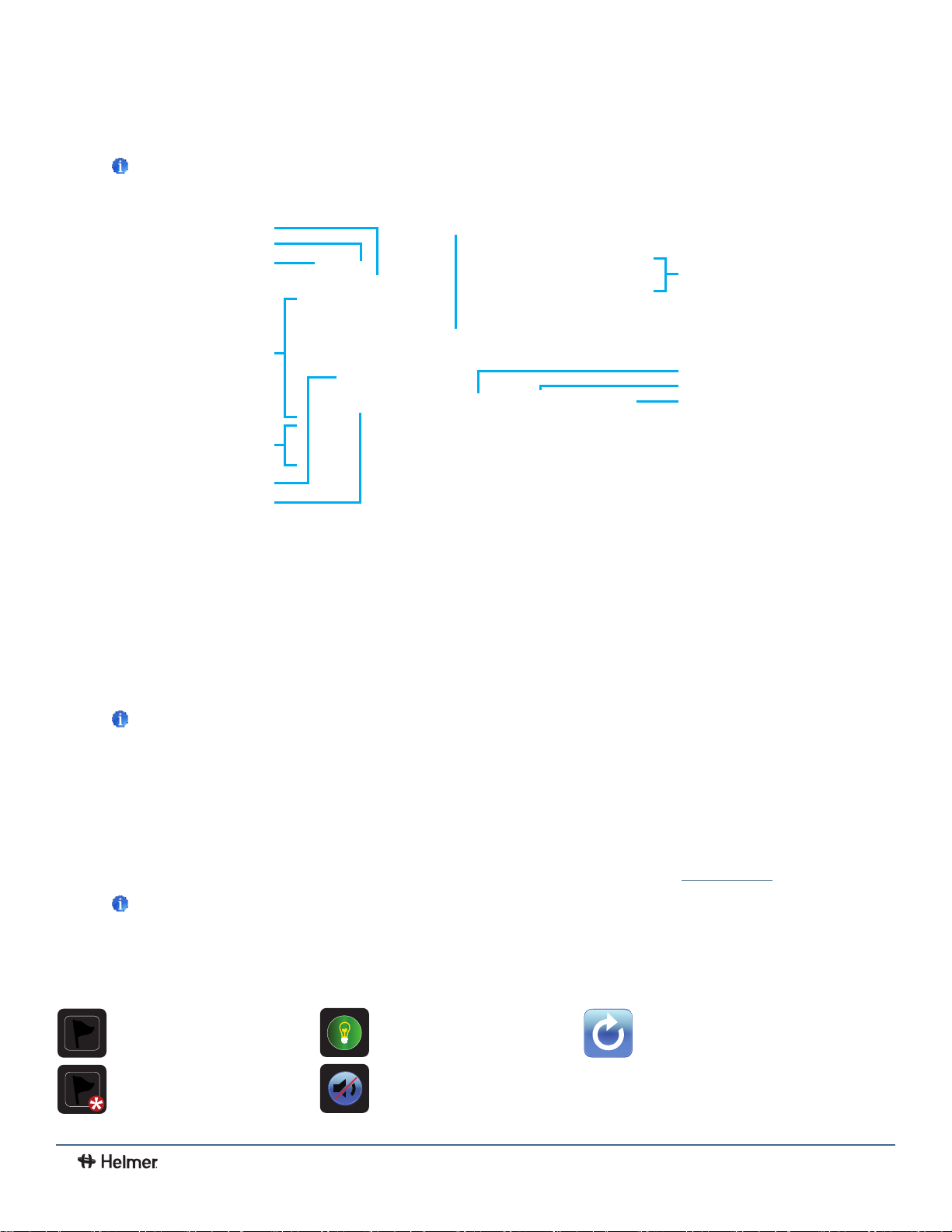
3 Home Screen Basics
Note
To temporarily silence active alarms, touch the Mute icon in the top right corner of the screen.
3
i.C
i.C3 User Guide
User Guide
Unit ID
Primary Monitor Probe
Screen ID
Event Log Icon-Indicator
Informaon Header
Display Zone
Min/Max Temperature Display
Min/Max Reset
Secondary Monitor Probe
(not available on all models)
i.C³ Applicaons
Alarm Condion Indicator
Alarm Condion Message
Home Screen Layout
The i.C3 Home screen is comprised of three information areas:
Information header - The dark blue horizontal band across the top of the Home screen. This header is displayed on all i.C3
screens. From left to right it includes: the Event Log icon, Screen ID, Unit ID, Date/Time, Battery indicator, Light On/O icon (if
applicable), and Mute icon.
Display zone - The middle band of the screen which includes information indicators and messages. From left to right, they are:
Status display; Alarm Conditions indicator and Alarm Conditions message; Primary Monitor Probe display; Min/Max Temperature
Display; and Secondary Monitor Probe display (if installed).
Notes
• Primary Monitor Probe refers to the monitoring probe located toward the top of the chamber.
• Secondary Monitor Probe (if installed) refers to the monitoring probe located toward the bottom of the chamber.
• Min/Max temperature display shows the highest and lowest Primary Monitor probe temperature occurrence within a given
period of time.
Application icons - Icons located at the bottom of the screen which include ve factory-preset application icons. From left to
right they are: i.C
can be changed or rearranged through the Icon Transfer feature. For more information refer to
Notes
• After two minutes of no interaction, the Temperature Graph screensaver is displayed (if enabled).
• Additional applications are available on the i.C3 APPS screen.
3
Applications (APPS), Settings, Temperature Graph, Automatic Alarm Test, and Information Logs. These icons
Icon Transfer.
Home Screen Icons and Indicators
Touch the Event Log icon to
navigate to the Event Log screen.
Look for the New Event indicator
(red asterisk).
Toggle the Light icon to turn the
light On or O (varies by models).
Touch the Mute icon to temporarily
silence alarm sound.
7
Touch the Reset icon to reset the
Min/Max display. Time since last
reset will be displayed.
360405/B
Page 9
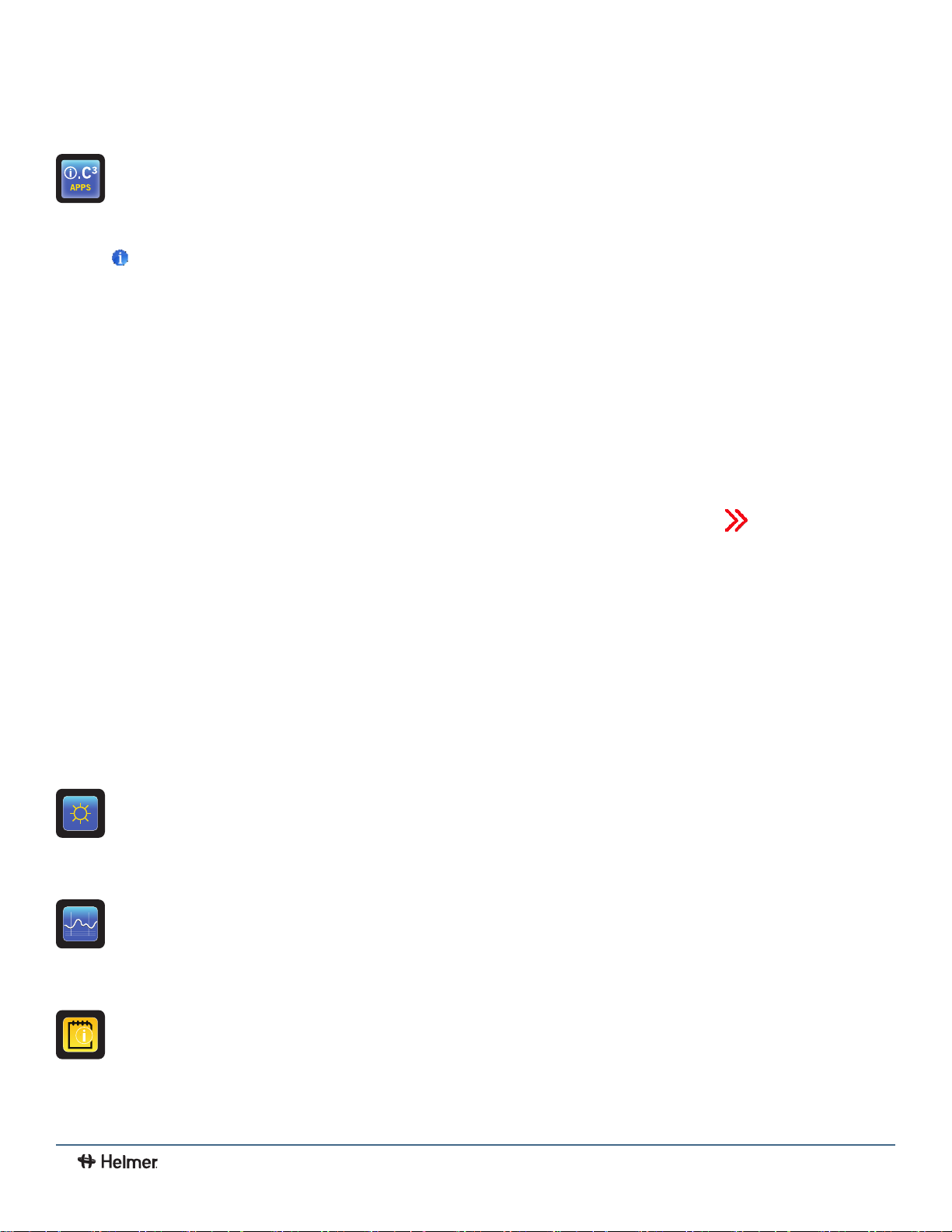
4 i.C3 Applications (APPS)
All i.C3 Applications can be reached from the i.C3 APPS screen.
Notes
• i.C3 Applications screen icons are interchangeable with those found on the Home screen.
• Primary Monitor probe reading and alarm conditions are displayed on the left side of the screen.
3
i.C
i.C3 User Guide
User Guide
Using i.C3 Applications
To navigate to an application screen, touch the associated application icon.
Contacts
View product support information including the rmware revision numbers.
Brightness Settings
Adjust monitor screen brightness.
Temperature Graph
View current and historical probe temperature data and alarm events.
Information Logs
Access all available data log applications.
8
360405/B
Page 10
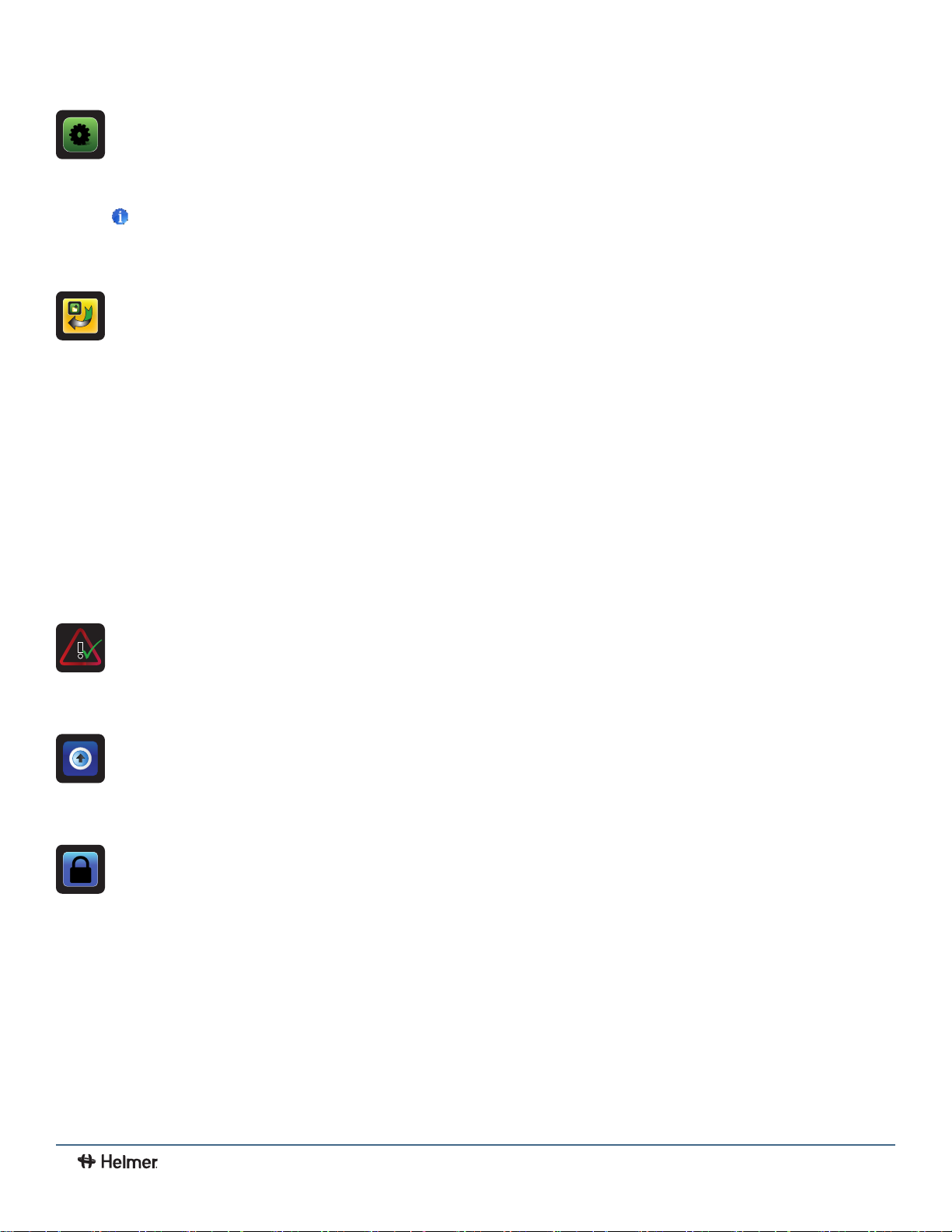
i.C3 Settings
3
All i.C
system settings are congured and other preferences selected from the i.C
Note
3
The i.C
accessing the i.C
Settings screen is password protected, unless password protection is turned O (from the i.C
3
for the rst time, use the factory-originated password (1234).
Icon Transfer
Reposition application icons on the Home and Applications screens.
CSV Downloads
Download information log(s).
3
Settings screen.
3
i.C
i.C3 User Guide
User Guide
3
Settings screen). If
PDF Downloads
Download historical information as a PDF.
Alarm Test
Initiate automatic alarm tests for the high and low temperature alarms.
Uploads
Upload rmware updates.
Access Control (if installed)
Display keypad for refrigerator access.
9
360405/B
Page 11

3
i.C
i.C3 User Guide
User Guide
5 T emperature Alarm T est
Initiate an automatic alarm test for the high and low temperature alarms. The unit uses a built-in Peltier device to heat or
cool the probe without aecting chamber temperature. The process normally takes less than ve minutes.
Note
Touch the Cancel Test icon at any time to abort the alarm test.
Initiate alarm test
1. Touch the High Alarm Test or Low Alarm Test icon to begin the alarm test. The icon for the selected test begins to
ash.
• Temperature changes are displayed in the Temperature Display on the left side of the screen.
• As the temperature moves into alarm conditions, the temperature reading turns red.
• The message "Peltier Test Probe Cooling (or Warming)" is displayed in the Alarm Condition area.
• When completed, the test result is displayed in the Test Status section of the display.
Note
If the temperature alarm test takes longer than ten minutes, the i.C3 will automatically cancel the test.
Cancel alarm test
1. Touch the Cancel Test icon to end the alarm test. "Test Stopped" is displayed in the Test Status section of the display.
At the time of an alarm test, the Alarm Test icon is displayed on the Temperature Graph to show the change in
temperature was test-induced. Event data for the alarm test is recorded and highlighted in blue in the Event Log.
10
360405/B
Page 12

3
i.C
i.C3 User Guide
User Guide
6 Min/Max Temperature Monitoring
The Min/Max temperature display shows the highest and lowest Primary Monitor probe temperature occurrence since the
last system reset (power-on event) or manually-initiated reset.
Notes
• The Min/Max temperature display can be turned on or o. Refer to Display Settings for more information.
• Once the time reaches the maximum display of 999 hours and 60 minutes, the message will display ">999:60", but minimum
and maximum temperatures will continue to be tracked.
Reset Min/Max temperature
1. Touch the Reset icon. The message "Reset min/max temperature memory?" is displayed along with the time (in hours and
minutes) since the last reset.
2. Touch to conrm. The timer is reset to 000.00 and the minimum and maximum recorded temperature is cleared. Or,
Touch to cancel.
11
360405/B
Page 13

3
i.C
i.C3 User Guide
User Guide
7 Temperature Graph
The Temperature Graph screen shows current and historical primary monitor probe temperature data and temperature events.
Note
Up to 62 days of temperature data can be viewed on the graph.
Alarm Condion Icon
Viewing the Temperature Graph
1. Toggle the graph Time Span button to select a 1-day or 7-day time span.
Note
To view all graph features (including Alarm Condition, Alarm Test, and Defrost Cycle indicators), select the 1-day time span.
Date, day and time information for the selected time span is displayed on the graph line.
• Upper line represents high alarm limit
• Lower line represents low alarm limit
• Temperature graph line turns green when unit is within alarm limits and red when outside alarm limits
• Graph is displayed in strip chart form. A black, dashed vertical line appears on the graph where there is a change in the
date or time. A white, dashed vertical line appears on the graph where there is a change in the high alarm limit or low
alarm limit. A gray, dashed vertical line appears on the graph where the unit is powered on.
Notes
• If the time or date are changed, the stored temperature data will not be reformatted with the new time conguration. Logged
events may be duplicated in the downloaded event database if the time or date is changed.
• The temperature graph displays 62 days of data.
• If the high alarm limit or low alarm limit are changed, a dashed vertical black line will appear on the temperature graph,
corresponding to date and time when the change was made.
12
360405/B
Page 14

3
i.C
i.C3 User Guide
User Guide
Event Data
Door Open Time Total time (in minutes) that the unit door was left open during the selected time span.
Door Openings Total number of times the unit door was opened during the selected time span.
Total Events Total number of logged events that occurred during the selected time span.
Viewable with the 1-Day Time Span
Graph Display of Alarm Condition
Alarm condition events are shown on the graph by a small Alarm Condition icon when an alarm has been activated. Data
and events are shown in 4-hour segments.
View detailed event data
1. Touch the Alarm Condition icon to navigate to the Event Log screen.
2. Touch the Event to view detailed event data.
Graph Display of Alarm Test
Alarm tests are shown on the graph by a small Alarm Test icon.
View alarm test data
1. Touch the Alarm Test icon to navigate to the Event Log screen.
2. Touch the Event to view detailed event data.
Graph Display Zoom Feature
The zoom feature may be used to allow a more detailed view of a particular segment of the temperature graph.
Using zoom feature
1. Touch to draw a box around the desired area on the temperature graph. The selected area will appear in the display.
2. Touch the to return to the expanded view.
13
360405/B
Page 15

3
i.C
i.C3 User Guide
User Guide
One Touch Quick Information Feature
The one touch quick information feature allows the user to view specic temperature information at any point on the
graph.
Using one touch
1. Touch the desired point on the graph. A dialog box will appear providing selected date, time and temperature data.
Note
The one touch feature should be used for reference only. The temperature displayed may vary from actual by 0.1 - 0.2 °C.
14
360405/B
Page 16
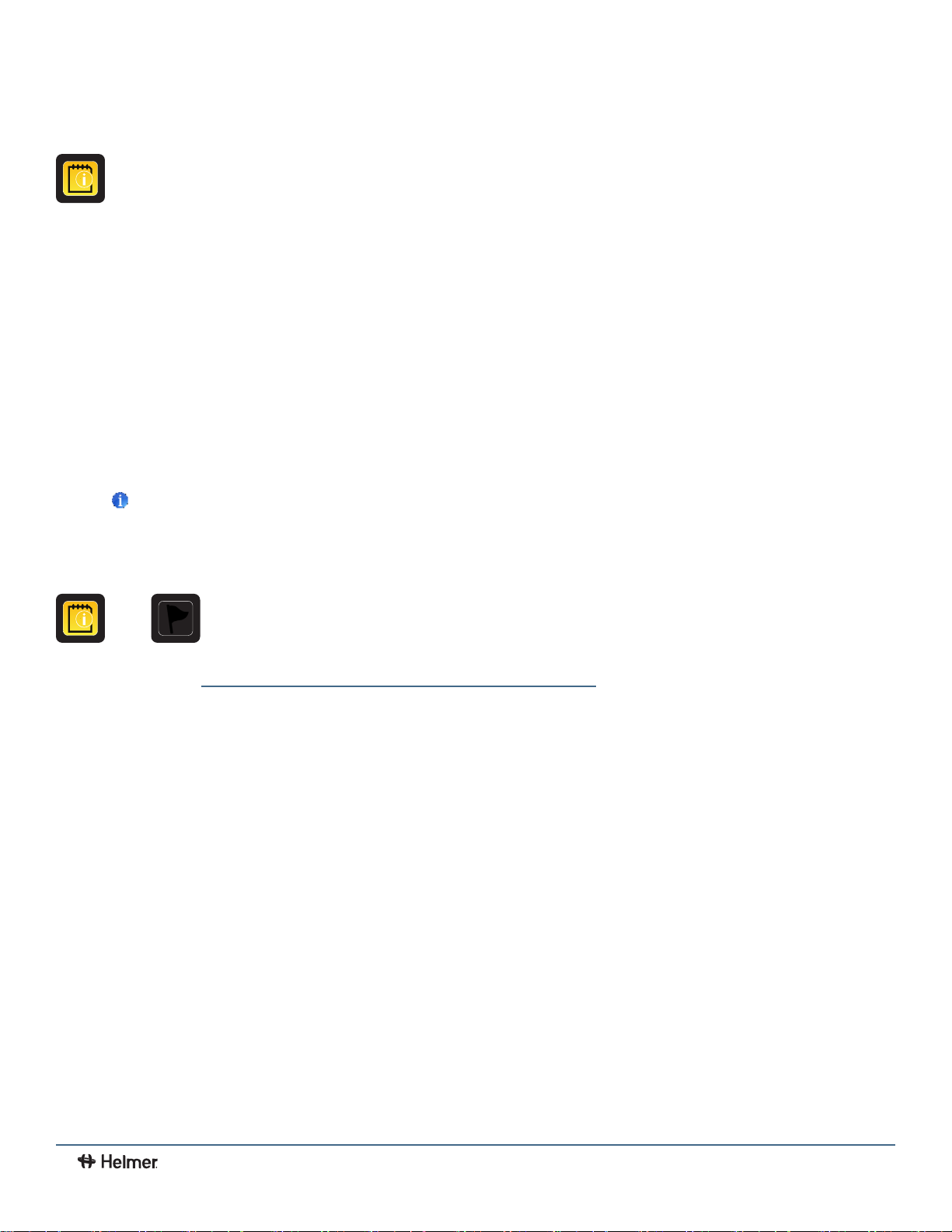
8 Information Logs
All available data logs are accessed from the Information Logs screen.
Note
Some icons shown may be specic to models or optional features.
3
i.C
i.C3 User Guide
User Guide
Event Log
>
The Event Log shows information from alarm events. A maximum of 100 (most recent) events can be viewed on the Event
Log screen. Refer to Data Transfer, Downloading Temperature and Event Data for more information.
Viewing the event log
1. Touch and hold the bidirectional arrows to scroll through the log.
2. Touch the desired Event to navigate to the Event Detail screen.
15
360405/B
Page 17

Information Found in the Event Log
• Type of event that occurred
• Date event occurred
• Time event condition began
• Temperature at start of alarm event
• Time event condition ended
• Temperature at end of alarm event
• Indicator of corrective action recorded
Event Log Formatting
Bold text Not yet viewed
Normal text Viewed
Dimmed text Downloaded
Data row shaded blue High or low alarm (triggered from an alarm test)
3
i.C
i.C3 User Guide
User Guide
16
360405/B
Page 18

3
i.C
i.C3 User Guide
User Guide
Event Log Detail Screen
The Event Log Detail provides additional temperature information for primary and secondary monitor probes, and the
compressor probe for an alarm event. The cause of an alarm event and the corrective action taken can be acknowledged.
Information Found in the Event Detail Log
• Type of alarm
• Start date/time of alarm
• End date/time of alarm
• Primary monitor probe start/end, maximum/minimum temperatures
• Secondary monitor probe start/end, maximum/minimum temperatures (if installed)
• Compressor start/end, maximum/minimum temperatures
Event Acknowledgement
Use the Event Acknowledgement buttons to select the cause of an alarm event and the corrective action taken.
Acknowledge an event
Note
If Other is selected for the event cause or action taken, the alphanumeric keyboard is displayed. Enter the cause or action
taken in the space provided.
1. Touch the Event Cause button. The Event Cause drop-down list is displayed.
2. Select and touch the cause of the alarm event (Door Open; Inventory; Alarm Test; Other).
3. Touch the Action Taken button. The Action Taken drop-down list is displayed.
4. Touch the action taken to correct the alarm event (Closed Door; Removed Contents; Completed Test; Other).
5. Touch the Signature button to display the alphanumeric keyboard and enter the user name or user initials.
6. Touch the Save icon. The message "Save?" is displayed.
7. Touch the to save the event information. A green check mark is displayed in the event row on the Event Log screen.
The date and time of the event acknowledgement is automatically added to the Signature button and the event information
can no longer be edited, or touch the to cancel the Save operation.
Note
All three elds must be completed for data to be saved. If the Home or Back icons are touched prior to touching the Save icon,
no information will be saved.
17
360405/B
Page 19

3
i.C
i.C3 User Guide
User Guide
Access Control Log (if installed)
>
The Access Control Log screen contains a record of each user-authenticated access event. A maximum of 100 (most
recent) events can be viewed on the Access Control Log screen. The Access Log shows information from controlled
access chamber entries.
Refer to Access Control for more information.
Note
The Access Control Log, with the Access Control screen and Access Control Setup screen, are activated when the Access
Control option is activated (Access Control is a factory-activated option).
Viewing the access control log
Touch and hold the bidirectional arrows to scroll through the log.
Information Found in the Access Control Log
• User (Name of user, Denied, or Override)
• Date of access
• Time of access
• Length of time door remained open
• Method of access (PIN, Key or Remote)
Access Log Formatting
Bold text New data since the last time the log was viewed
Normal text Viewed
Dimmed text Downloaded
Red text Incorrect PIN entered, access denied, or key override was used
18
360405/B
Page 20

9 Data Transfer
CSV Download
Use the CSV Download screen to download information.
3
i.C
i.C3 User Guide
User Guide
Download Data
1. Insert a memory device into the USB port located on the right of the i.C3 monitor bezel. When the memory device is
detected, the message "Insert USB Flash Drive" clears and the Data Selection spin buttons are no longer shaded.
2. Touch the Date Range buttons to select the desired beginning (left) and ending (right) dates. The Data Report Calendar
screen is displayed.
3. Touch the desired date on the calendar then touch the to conrm, or the to cancel.
4. Select User to download a single log or data set, or Tech for all log les.
19
360405/B
Page 21

i.C3 User Guide
5. Touch the Start Download button to begin the download. The Download Status bar becomes active showing the progress of
the download. When nished, the message "Data download complete" along with the number of les downloaded. A date
and time stamp will appear below the completion message.
Note
If the Download icon is touched before a memory device is inserted, the message "Insert USB Flash Drive" is displayed until a
memory device is inserted.
6. Remove the memory device from the USB port. The CSV le may be viewed, saved, and manipulated on a PC. If the
memory device is removed before the data download is complete, or if the memory device is full, the message "Flash drive
has been removed" will appear below the progress bar. If the memory device is full, the message "Flash drive is full" will
appear below the progress bar.
Notes
• The data is best viewed with an application used to create spreadsheets or databases. If Microsoft® Excel™ is used to view
data, version 2009 or newer is required.
• If the USB is disabled in the Auxiliary Setting screen, the message "USB port is currently disabled" is displayed. Refer to
i.C3 Settings, Auxiliary Systems for information regarding enabling the USB port.
• The Download screen can not be closed during a data download unless an error occurs.
• Up to 3 months of data may be downloaded at a time.
• If an invalid date range has been entered, the message "The date range must not exceed 3 months. Please select beginning
and end dates that encompass 3 months or less" will appear
• A User download should be completed in less than twenty minutes. If the download has not completed in twenty minutes,
contact Helmer Technical Service.
• The i.C3 features two Disk Space status alarms to proactively alert you when the available storage space is low (about
3 month's of data can be stored), and full (no new data can be stored). If either of these appear, contact
Helmer Technical Service.
Downloaded data is saved to the memory device in CSV (comma separated values) le format. When set to User, the
following four les can be saved each time.
• Primary Monitor Probe temperature data (Data is sampled once per minute)
• Secondary Monitor Probe temperature data (if installed and activated)
• Event log data
• Access log data (if Access Control is activated)
Setting the toggle to Tech allows download of additional diagnostic les. After the les are transferred, the read/write
properties of the downloaded les should be set to read-only by the user.
20
360405/B
Page 22

Downloading Temperature Graphs and Alarm Event Data to PDF
Use the PDF Download screen to download information to PDF (Portable Document Format).
1. Insert a memory device into the USB port located on the right of the i.C3 monitor bezel. When the memory device is detected,
the message "Insert USB Flash Drive" clears. The Start Download and Data Selection buttons are no longer shaded.
2. Touch the Date Range buttons to select the desired beginning (left) and ending (right) dates. The Data Report Calendar
screen is displayed for each date.
3. Touch the desired date on the calendar, then touch the to conrm, or the to cancel.
3
i.C
i.C3 User Guide
User Guide
4. Select the desired Report Duration.
• 1-day duration selects all applicable one-day graphs and Alarm Event Data reports for the product and date range.
• 7-day duration selects all applicable seven-day graphs and Alarm Event Data reports for the date range.
• All duration selects all the applicable one-day and seven-day graphs and Alarm Event Data reports for the date range.
5. Touch the Start Download button to begin the download. The Download Status bar becomes active showing the progress
of the download. When nished, the message "Data download complete" along with the number of les downloaded. A date
and time stamp will appear below the completion message.
6. Remove the memory device from the USB port. The PDF le may be saved or printed from a PC. If the
memory device is removed before the download is complete, the message "Flash drive has been removed" will appear below
the progress bar. If the memory device is full, the message "Flash drive is full" will appear below the progress bar.
Notes
• If the PDF Download icon is touched before a memory device is inserted, the message "Insert USB Flash Drive" is displayed
until a memory device is inserted.
• The paper setting selected is stored with the report being run and cannot be changed when rerunning the same report at a
later date. Changing the paper setting will aect the current report being run as well as subsequent reports.
• PDF reports are stored for about 3 months, at which time the oldest reports are purged to free up storage space. Helmer
recommends performing PDF downloads every two months.
21
360405/B
Page 23

3
i.C
i.C3 User Guide
User Guide
Uploading Firmware Updates
Use the Upload screen to upload rmware updates. If the Upload icon is touched before a memory device is inserted, the
message "Insert USB Flash Drive" is displayed until a memory device is inserted.
Notes
• Record the display processor and control processor rmware version number before uploading a rmware update. These
numbers will be referenced after the update to ensure the update was successful.
• Record the Control Sensor Oset temperature value. These values will be referenced if the rmware update causes a
change to the oset values.
• The Upload screen can not be closed during a data upload unless an error occurs.
• If the USB is disabled in the Auxiliary Setting screen, the message "USB port is currently disabled" is displayed. Refer to
i.C3 Settings, Auxiliary Systems for information regarding enabling the USB port.
Upload rmware
1. Insert a memory device into the USB port located on the right of the i.C3 monitor bezel. When the memory device is
detected, the message "Insert USB Flash Drive" clears and the Upload icon is no longer shaded.
22
360405/B
Page 24

2. Touch the Upload icon to begin data transfer. The upload progress bar is displayed.
3. When nished, the "Data Upload Completed" message and the date and time are displayed. The screen then refreshes to
display the "Wait" screen, and the system automatically powers down and restarts.
3
i.C
i.C3 User Guide
User Guide
4. Remove the memory device from the USB port. Updated rmware is loaded to the i.C3 memory.
5. After the i.C3 system restarts, verify the display processor (DP) and/or control processor (CP) rmware version number
have been updated. If either rmware version number has not been updated from the recorded version number, contact
Helmer Technical Service. For more details regarding referencing the rmware revision number, refer to
i.C3 Applications (APPS), Using i.C3 Applications
6. Verify the Control Sensor Oset temperature value has not changed. If the temperature oset value has been changed
from the recorded value, calibrate the oset value. For details on calibrating the oset values, refer to
Sensor Calibration and Control, Sensor Calibration.
23
360405/B
Page 25
10 Customizing the i.C3 Screen
Brightness Settings
>
3
i.C
i.C3 User Guide
User Guide
The backlight on the i.C
3
monitor has three brightness settings. Touch any button to select a dierent brightness setting.
Home Page Screensaver
>
The Home screen is equipped with a screensaver that displays a 24-hour temperature graph. The screensaver is
automatically displayed after two minutes of inactivity on the Home screen. Touch anywhere on the screensaver to return
to the Home screen.
24
Notes
• Inactivity of two minutes duration on most i.C3 screens results in automatic return to the Home screen.
• The screensaver can be disabled on the Settings screen so the Home screen is viewable at all times.
360405/B
Page 26

3
i.C
i.C3 User Guide
User Guide
11 i.C3 Settings
>
Congure i.C
Password Protection of the i.C3 Settings Screen
Password protection is set to ON at the factory and can be turned OFF through the settings menu. A password protects
i.C3 settings from unauthorized changes.
If password protection is turned ON, touch the i.C
If accessing the i.C
If password protection is turned OFF, touch the i.C3 Settings icon to navigate directly to the i.C3 Settings screen.
3
system settings and other preferences via i.C3 Settings.
Note
3
The i.C
Helmer recommends password protection remain ON.
system requires up to 30 seconds to save conguration changes. Do not turn the power o until 30 seconds have elapsed.
Note
Accessing Settings
3
3
for the rst time, use the factory-originated password (1234).
Settings icon to bring up a numeric keypad and enter the current password.
25
360405/B
Page 27

Temperature Setpoint
The Temperature Setpoint species the desired temperature for product stored inside the unit.
Change temperature setpoint
Touch the minus (-) or plus (+) on the spin box to adjust the temperature setpoint.
Device Control Settings
The Device Control Settings screen displays the current settings used to control the unit.
View settings
Touch the Device Control Settings button to view the
following settings:
• Temperature Setpoint - the temperature at which the
unit operates
• Upper Rail - maximum control temperature at which the
compressor will turn on
• Lower Rail - minimum control temperature at which the
compressor will turn o
• Delay on Start-up - delays the compressor startup in the
event of a power interruption
• Speed During Probe Error - Speed at which compressor
will run as a percent of maximum if both monitor and
control probe fails
3
i.C
i.C3 User Guide
User Guide
Note
• Temperature Setpoint can be adjusted through the main Settings screen and Device Control Settings.
• Upper Rail, Lower Rail, Delay on Start-up and Speed During Probe Error settings are set at the factory and should
not be changed. For information regarding changing these settings, contact Helmer Technical Service.
26
360405/B
Page 28

Alarm Settings
Parameters for activating an alarm may be set through Alarm Settings.
Set alarm parameters
1. Touch the Alarm Settings button.
2. Touch the minus (-) or plus (+) on the corresponding Setpoint spin box to change an alarm setpoint.
3. Touch the minus (-) or plus (+) on the corresponding Time Delay spin box to change the time delay duration.
3
i.C
i.C3 User Guide
User Guide
27
360405/B
Page 29

Users and Passwords
Set up user access and passwords, or turn password protection on or o through Users and Passwords.
Enable/disable password protection
1. Touch the Users and Password button.
2. Toggle the Password Protection button to turn password
protection On or O.
Note
Helmer recommends that password protection remain On.
Change password
1. Touch the Users and Password button.
2. Touch the Change Password button, a numeric keypad
appears.
3. Enter a new 4-digit password.
4. Touch to save of to cancel.
3
i.C
i.C3 User Guide
User Guide
Establishing user access (if installed)
1. Touch the Users and Password button.
2. Touch the Access Setup button, the Access Setup numeric
keypad appears.
3. Refer to Access Control for instructions regarding Access
Control setup and operation.
28
360405/B
Page 30

Sound Settings
Turn sounds on or o, control volume and select an alarm tone through Sounds Settings.
Enable/disable sounds
1. Touch the Sounds Settings button.
2. Toggle the Sounds button On or O to select desired
setting.
Set alarm volume
1. Touch the Sounds Settings button.
2. Touch the minus (-) or plus (+) on the Alarm Volume spin
box to select desired volume.
Select alarm tone
1. Touch the Sounds Settings button.
2. Touch the plus minus (-) or plus (+) on the Alarm Tone spin box to select desired tone.
3. Touch the Try It button to hear the selected tone.
3
i.C
i.C3 User Guide
User Guide
29
360405/B
Page 31

Display Settings
Control how information appears on the i.C3 display through Display Settings.
Change language
1. Touch the Language button. The language drop-down list
is displayed.
2. Touch the language to be displayed. The selected language
is displayed in the Language button.
3. Touch to conrm language selection, or to
cancel.
4. Touch the Home icon to continue to the Home screen.
Select date format
1. Touch the Display Settings button.
2. Toggle the Date Format button to select the desired format.
Select time format
1. Touch the Display Settings button.
2. Toggle the Time Format button to select the desired format.
3
i.C
i.C3 User Guide
User Guide
Select temperature units
1. Touch the Display Settings button.
2. Toggle the Temperature Units button to select the desired format.
Enable/disable Temperature Graph Screensaver
1. Touch the Display Settings button.
2. Toggle the Temperature Graph Screensaver button On or O to select desired setting.
Change unit ID
1. Touch the Display Settings button.
2. Touch the Unit ID button. An alphanumeric keyboard appears.
3. Enter desired ID (maximum 10 characters).
4. Touch to save, or to cancel.
Enable/disable Min/Max display
1. Touch the Display Settings button.
2. Toggle the Min/Max Display button On or O to select desired setting.
Enable/disable Access Control as home screen (if installed)
Note
If O is selected, the standard Home screen is displayed and keypad access is obtained by touching the Access Control icon.
1. Touch the Display Settings button.
2. Toggle the Access Control as Home Screen button On or O to select desired setting.
30
360405/B
Page 32

Light Control Settings (if installed)
The Light Control Settings screen provides a way to control interior lights as well as set the Light O Delay.
Enable/disable interior light
1. Touch the Light Control Settings button.
2. Toggle the Light Enabled button YES or NO to select
desired setting.
Set light o delay
1. Touch the Light Control Settings button.
2. Toggle the Light O Delay button YES or NO to select
desired setting.
3. Touch the minus (-) or plus (+) on the Light O Delay spin
box to select desired time.
Device Status and History
Current sensor readings and device status are displayed on the Device Status screen.
3
i.C
i.C3 User Guide
User Guide
31
Note
The Spare Probe/RTD-3 is found only on refrigerator device status.
360405/B
Page 33

3
i.C
i.C3 User Guide
User Guide
Sensor Calibration
Calibration adjusts temperature setpoints so the value displayed matches the actual chamber temperature, as measured
by an independent thermometer. View temperature probe readings and adjust osets through Sensor Calibration.
Sensor Reference
Indicates probe location on the control board.
Current Reading (+ Oset)
View the real-time temperature reading which includes oset calculation.
Oset
The spin boxes are used to calibrate the temperature probe readings using the oset values. Touch the minus (-) or plus
(+) on the adjacent spin box until the correct value is displayed.
Adjust temperature setpoint
1. Touch the Sensor Calibration button.
2. Touch the minus (-) or plus (+) on the corresponding probe spin box to adjust the oset.
Notes
• Primary and secondary monitor probe temperature osets may require periodic calibration. Refer to the product service
manual for instructions regarding calibrating chamber temperature probes.
• The Compressor Probe oset is set at the factory. Contact Helmer Technical Service for information regarding changing the
Compressor Probe oset.
• The Spare Probe/RTD-3 is found only on refrigerators.
Date/Time
Date and time values can be changed through the Date/Time
screen.
Change/set date and time
1. Touch the Date/Time button.
2. Touch the minus (-) or plus (+) on the corresponding
Date or Time spin box to select the appropriate value.
3. Toggle the AM/PM button to select AM or PM.
4. Touch to save.
32
360405/B
Page 34

Auxiliary Systems
The Auxiliary Systems screen provides a way to turn the USB
port or Ethernet port on or o, as well as set up an Ethernet
connection.
Enable/disable USB or Ethernet ports
1. Touch the Auxiliary Systems button.
2. Toggle the corresponding port button On or O to select
desired status.
Note
Contact Helmer Technical Service for Ethernet API
information to utilize this interface.
Restore Factory Settings
Settings will be restored to their factory default through Restore
Factory Settings.
Restore factory Settings
1. Touch the Restore Factory Settings button. The Restore
Factory Settings conrmation box appears.
2. Touch to conrm, or to cancel.
3
i.C
i.C3 User Guide
User Guide
Note
• Restoring factory settings will result in the loss of any
changes made to Alarm Settings, Temperature Setpoints,
or Time Delay settings.
• The Language setting and Unit ID will not be overridden when restoring factory settings.
33
360405/B
Page 35

System Functions
Reboot or shut down the i.C3 system through System Functions.
Restart display
1. Touch the System Functions button.
2. Touch the Restart Display button. The conrmation
box appears.
3. Touch to conrm, or to cancel.
Shut down display
1. Touch the System Functions button.
2. Touch the Shut Down Display button. The conrmation
box appears.
3. Touch to conrm, or to cancel.
Notes
• The i.C3 system should be shut down prior to shutting
down the entire unit.
• If only the i.C3 system is shut down, the unit will continue
to run based on the last settings. No temperature data
other than Min/Max will be recorded.
3
i.C
i.C3 User Guide
User Guide
34
360405/B
Page 36

3
i.C
i.C3 User Guide
User Guide
12 Access Control (if installed)
Integrated Electronic Access Control limits user access, providing secure storage. A valid personal identication number
(PIN) must be entered to open the unit.
Notes
• There is a lock override key on Helmer equipment. The key disconnects power to the magnetic lock, allowing users to
access the contents of the cabinet. A keyed mechanical lock is provided on the door to allow secure access if the magnetic
lock is overridden. In the event of an AC power failure, the magnetic lock override key should be switched to override
position and the mechanical key lock should be used to provide secure access until AC power is restored.
• Refer to the product operation manual for detailed instructions on using the Access Control lock under normal conditions
and during an AC power failure.
Access Control Setup
The Access Control Setup screen allows management of multiple user proles. Up to 100 user proles can be created.
Notes
• Access Control must be set up prior to use.
• The Supervisor PIN must be used to set up user proles.
• The Supervisor PIN does not allow access to the unit. At least one user ID must be set up to gain access to the unit.
• The Supervisor PIN should be changed to prevent unauthorized user ID setup. The Supervisor PIN can not be deleted.
• In the event the Supervisor PIN is unavailable, contact Helmer Technical Service to reset the Supervisor PIN.
Note
The Access Setup button can be found on the Users and Passwords screen or the Access Log screen.
Entry into Access Control Setup
1. Touch the Access Setup button. A numeric keypad is displayed.
2. Enter the supervisor PIN ( if entering for the rst time, use the factory supervisor PIN = 5625).
3. Touch to conrm. The keypad closes and the Access Control Setup screen is displayed.
Add a user prole
1. Touch the Add User button. An alphanumeric keyboard is displayed.
2. Enter the User ID for the new user prole.
3. Touch the to store the user ID. The alphanumeric keyboard is displayed.
4. Enter a 4-digit PIN for the new user prole.
5. Touch the to store the user PIN. The User ID and PIN for the new user prole are displayed in the table.
35
360405/B
Page 37
3
i.C
i.C3 User Guide
User Guide
Delete a user prole
1. Touch the data row of the user prole to be deleted. The data row is highlighted in blue.
2. Touch the Delete User button. The message "Delete User?" is displayed.
3. Touch to conrm, or to cancel.
Edit a user prole
1. Touch the data row of the user prole to be edited. The data row is highlighted in blue.
2. Touch the Edit PIN button. The numeric keypad is displayed.
3. Enter a new 4-digit PIN.
4. Touch to conrm. The numeric keypad closes and the new PIN is displayed in the table, or
touch to cancel.
Access Control Screen
>
Temperature and Alarm Conditions are displayed on the left side of the keypad. When the screen is rst displayed, the
Closed Padlock indicator is displayed. "Enter PIN" is displayed above the locked indicator.
Using Access Control to unlock the door
1. Enter unique 4-digit PIN.
2. If a valid PIN is entered, the Padlock indicator appears open and the door is unlocked.
36
360405/B
Page 38

3
i.C
i.C3 User Guide
User Guide
Access Control as the Home Screen
If the Access Control option is activated, the Access Control Home Screen can be substituted for the standard Home Screen.
Notes
• It is recommended the Access Control icon be moved to the Home screen if the Access Control Home screen is disabled.
Refer to Icon Transfer for more information.
• If the Access Control Home Screen is disabled, the keypad is accessed by touching the Access Control icon.
Enable/disable Access Control Home Screen
1. Touch the i.C3 Apps icon.
2. Touch the Settings icon.
3. Touch the Display Settings button.
4. Toggle the Access Control as Home Screen button On or O to select desired setting.
37
360405/B
Page 39

3
i.C
i.C3 User Guide
User Guide
13 Icon Transfer
>
The Icon Transfer allows icons to be moved between the Home screen and the i.C3 Applications screen, or repositioned
on the i.C
3
APPS screen. A maximum of ve icons can be displayed on the Home screen.
Reposition icons
Drag icons with a touch-drag motion of the nger. Drag the selected icon directly over the icon that is currently located in the
targeted position.
Note
The i.C3 APPS icon appears dimmed because it must remain in the rst position (top left) on the Home screen and cannot
be transferred.
38
360405/B
Page 40
3
i.C
i.C3 User Guide
User Guide
Appendix A - Icon Reference Guide
Common Buttons
Buttons are included to adjust settings or navigate to a dierent "app". Alphanumeric keyboard buttons for text entry,
editing, save/cancel functions, and uppercase and lowercase keyboards are included for all languages. The extended
character keyboard and symbol keyboard are included for U.S./international languages only.
Notes:
• When the Extended Character button is touched, the uppercase extended character keyboard is displayed by default. To
display the lowercase extended character keyboard, touch the Lowercase button.
• Touch and hold the Back button to delete multiple characters.
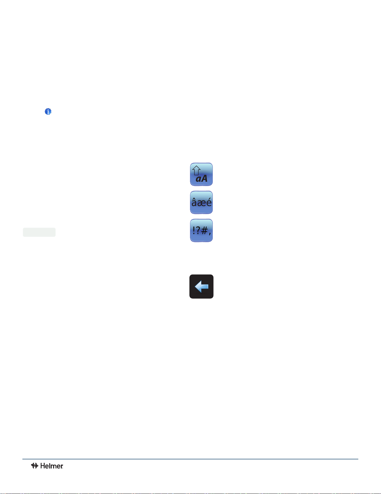
i.C3 Apps Buttons Alphanumeric Keyboard Buttons
Toggle box
Spin box
Navigation or Setting button
Toggle the Uppercase/Lowercase button to navigate
between the lowercase and uppercase character
keyboard.
Touch the Extended Character button to navigate to the
extended character keyboard.
Touch the Symbol button to navigate to the symbol
keyboard.
Touch the Space button to insert a space after a
character
Touch the Back button to delete a character from the text
window.
39
360405/B
Page 41
Application Icons
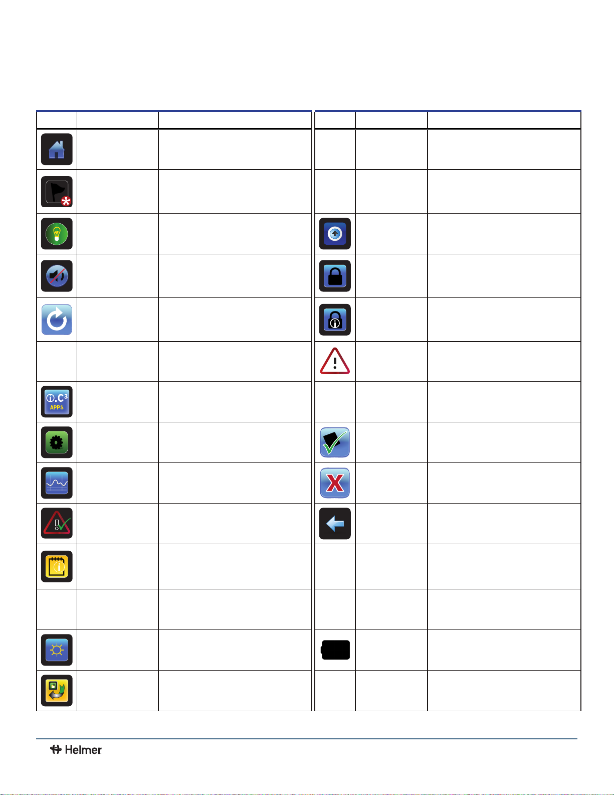
All i.C3 Apps icons are included in this guide. Contact Helmer, Inc. for information about optional applications.
3
i.C
i.C3 User Guide
User Guide
Image Name
Home • Navigate to the Home screen CSV Download
Event Log
(icon-indicator)
Light On/O
(button)
Mute On/O
(button)
Reset
Zoom Information
i.C³ Applications
(APPS)
Function
• Navigate to the Event Log
• Red asterisk indicates new event
• Refrigerator models only
• Toggle light On or O
• Touch once to temporarily silence an
active alarm
• Touch repeatedly to increase the
mute timer duration
• Touch to reset Min/Max temperature
display
• Touch to reset temperature graph
view
• Touch to view instructions for using
the temperature graph zoom feature
• Navigate to the i.C³ APPS screen Cancel Test • Touch to cancel Alarm Test
Image Name
PDF Download
Upload
Access Control
Access Log
Alarm Conditions
(icon-indicator)
Function
• Navigate to the CSV Download screen
• On the CSV Download screen, start a
data transfer
• Navigate to the PDF Download
screen
• On the Download screen, start a data
transfer
• Navigate to the Upload screen
• On the Upload screen, start a data
transfer
• Optional feature
• Navigate to the Access Control Login
screen
• Optional feature
• Navigate to the Access Control Log
• Indicates alarm event occurred
• Navigate to the Event Log
i.C³ Settings • Navigate to the i.C³ Settings screen Save • Touch to save entry or change
Temperature Graph
Alarm Test
Information Logs • Navigate to the Information Logs Scroll Arrows
Contact Information/
Contact Helmer
Display Brightness
Icon Transfer • Navigate to the Icon Transfer screen
• Navigate to the Temperature Graph
screen
• Navigate to the Alarm Tests screen
• Initiate an Alarm Test
• Navigate to the Helmer Contact
Information screen
• Navigate to the Display Settings
screen
Cancel • Touch to cancel entry or change
Back Arrow • Navigate to the previous screen
• Indicates additional information is
available by scrolling
Temperature
Graph Forward/
Back Arrows
Battery Power
(indicator)
• Navigate forward or backward to view
temperature graph data
• Indicates i.C³ is running on battery
40
360405/B
Page 42
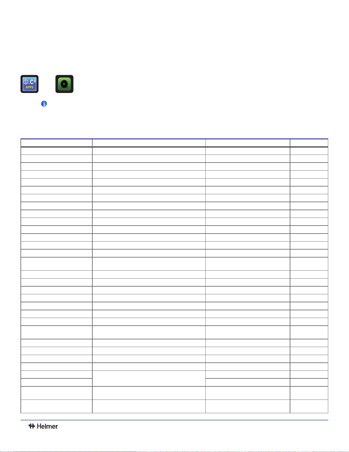
3
i.C
i.C3 User Guide
Appendix B - i.C3 Reference Guide
General Settings
>
Notes
• All i.C3 settings are shown in this guide. Contact Helmer, Inc. for information about settings as they pertain to optional
applications.
• Refrigerator defrost event settings are only applicable to models with the low humidity option.
Setting Description Default Value Range
Temperature Setpoints Set unit operation temperature Refer to product Service Manual
Alarm Settings Access alarm setpoint settings Refer to Alarm Settings table
Password Protection Protect i.C
Change Password Change password used to access i.C
Access Setup
Sounds Turn sound on or off
Alarm Volume Audible alarm volume 9 1 - 9
Alarm Tone Audible alarm tone 3 1 - 4
Mute Duration 15 1 - 60
Language Language displayed on the i.C
Date Format Date display format MM/DD/YY
Day Calendar day Set at the factory
Month Calendar month Set at the factory
Year Calendar year Set at the factory
Time Format
Minute Minute value Set at the factory
Hour Hour value Set at the factory
AM/PM AM or PM Set at the factory
Temperature Units Temperature units in °C or °F °C °C or °F
User/Tech Toggle Data log file selection User
Temperature Graph Screensaver Display temperature graph as Home screen On
Alternate Screensaver
Unit ID Unique identification number for the i.C
Min/Max Minimum and Maximum Primary Monitor Probe readings On
Access Control as Home Page Display Access Control keypad on the Home screen On
Brightness i.C3 display screen brightness 3 (brightest) 1 - 3
Light Enabled
Light Off Delay
Light Off Delay Time
Sensor Calibration
Primary Monitor Probe Offset
(if installed) Prevent chamber access without entry of a valid PIN On
Time display format 12-hour 12-hour or 24-
(optional) Display alternate screensaver as Home screen Off
(if installed) Turn Light Off Delay feature on or off Yes
(if installed) Duration the chamber light will remain on after the
(if installed) 5 minutes 1 - 99 minutes
door has closed
Set probe temperature values to match measured
temperature values
Offset value used to adjust temperature reading of
the primary monitor temperature probe.
3
Settings from unauthorized changes On
3
Settings 1234
(does not include alarms) On
3
screen English
3
system Unit serial number
(if installed)
Refer to product Service Manual
varies
hour
Max 10 characters
On
-10 °C - +10 °C
-18 °F - +18 °F
User Guide
41
360405/B
Page 43
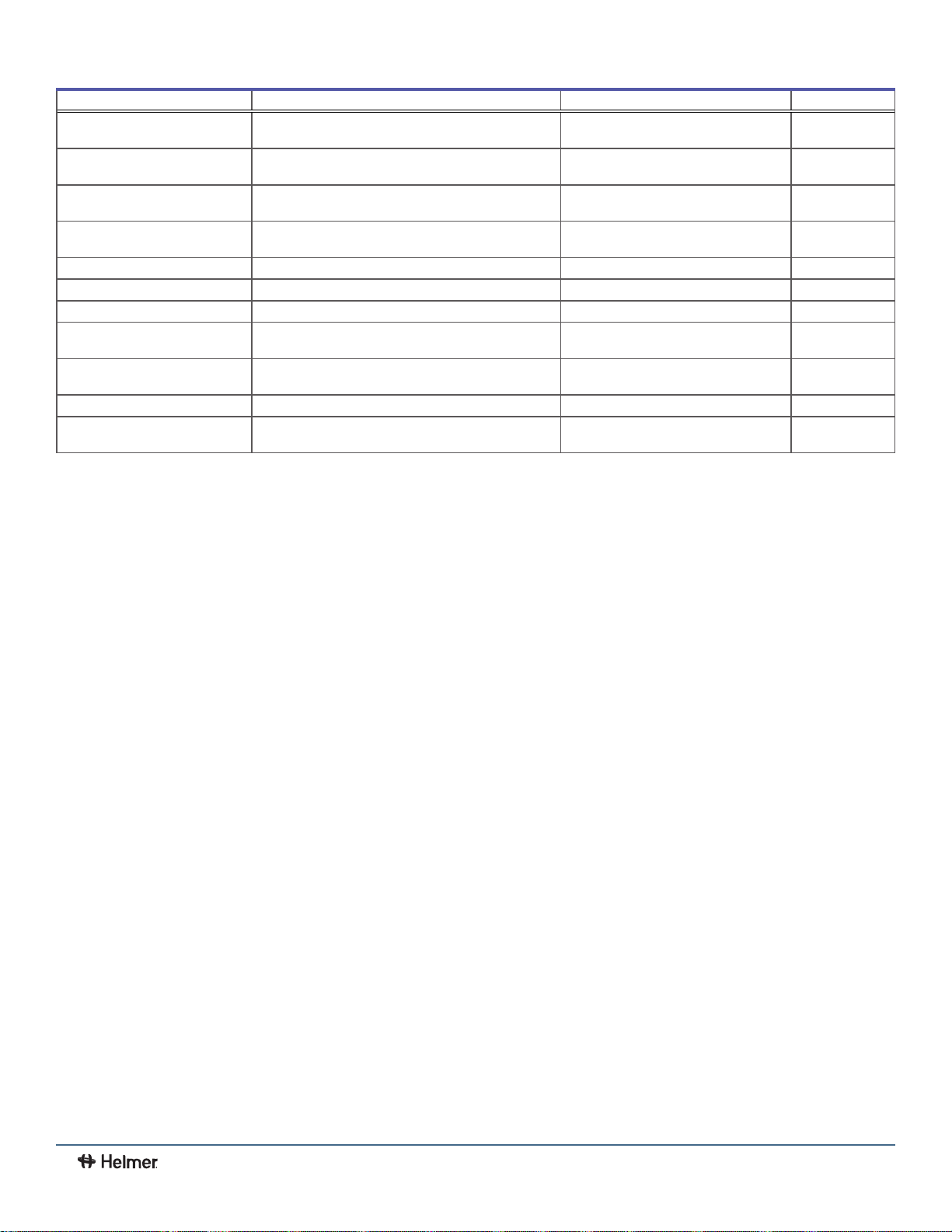
3
i.C
i.C3 User Guide
User Guide
Setting Description Default Value Range
Secondary Monitor Probe Offset
(if installed)
Control Probe Offset
Compressor Probe Offset
Spare Probe Offset
USB Port Turn USB port on or off On
Ethernet Port Turn Ethernet Port on or off Off
Restore Factory Settings Change all settings to factory default values Refer to product Service Manual
Upper Rail
Lower Rail
Delay on Startup Compressor start up delay 1 minutes 1 - 20 minutes
Speed During Control
Probe Error
(if installed)
Offset value used to adjust temperature reading of
the the secondary monitor temperature probe
Offset value used to adjust temperature reading of
the control probe
Offset value used to adjust temperature reading of
the compressor probe
Offset value used to adjust temperature reading of
the spare probe
Maximum temperature at which the compressor will
turn on
Minumum temperature at which the compressor will
turn off
Speed at which compressor will run as a percent of
maximum if both monitor and control probes fail
varies
varies
varies
varies
0.7 °C
-0.7 °C 0.1 °C - 10.0 °C
50% 0 - 100%
-10 °C - +10 °C
-18 °F - +18 °F
-10 °C - +10 °C
-18 °F - +18 °F
-10 °C - +10 °C
-18 °F - +18 °F
0.1 °C - 10.0 °C
0.1 °F - 18.0 °F
0.1 °F - 18.0 °F
42
360405/B
Page 44
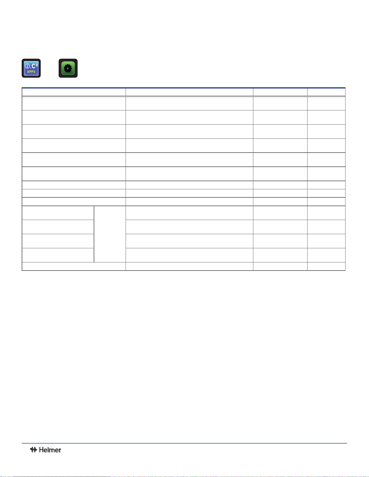
3
i.C
i.C3 User Guide
User Guide
Alarm Settings
> > Alarm Settings
Setting Description Default Value Range
Primary Monitor Probe High Temp (setpoint) High temperature at which alarm condition occurs 5.5 °C
Primary Monitor Probe High Temp (time delay) Time after high temperature alarm condition occurs until
Primary Monitor Probe Low Temp (setpoint) Low temperature at which alarm condition occurs 1.5 °C
Primary Monitor Probe Low Temp (time delay) Time after low temperature alarm condition occurs until
Compressor High Temp (setpoint) High temperature at which alarm condition occurs 50 °C 25 - 80 °C
Compressor High Temp (time delay) Time after high temperature alarm condition occurs until
Power Failure Time after power failure occurs until alarm sounds 1 minute 0 - 99
Probe Failure Time after probe failure occurs until alarm sounds 0 minutes 0 - 99
Door Open (Time) Time door remains open until alarm sounds 3 minutes 0 - 99
Secondary Monitor Probe High
Temp (setpoint)
Secondary Monitor Probe High
Temp (time delay)
Secondary Monitor Probe Low
Temp (setpoint)
Secondary Monitor Probe Low
Temp (time delay)
Low Battery Triggered after approximately 18 hours of use Not adjustable
(if installed)
alarm sounds
alarm sounds
alarm sounds
High temperature at which alarm condition occurs 5.5 °C
Time after high temperature alarm condition occurs until
alarm sounds
Low temperature at which alarm condition occurs 1.5 °C
Time after low temperature alarm condition occurs until
alarm sounds
(iBR and iLR models)
6.5 °C (iPR models)
0 minutes 0 - 20
(iBR models)
2.0 °C (iLR and iPR models)
0 minutes 0 - 20
0 minutes 0 - 99
(iBR and iLR models)
6.5 °C (iPR models)
0 minutes 0 - 20
(iBR models)
2.0 °C (iLR and iPR models)
0 minutes 0 - 20
-100 - +50 °C
-148 - +122 °F
-100 - +50 °C
-148 - +122 °F
77 - 176 °F
-100 - +50 °C
-148 - +122 °F
-100 - +50 °C
-148 - +122 °F
43
360405/B
Page 45

Event Log Codes
Event Code Description Event Code Description
1 Compressor Probe Failure 14 Primary Monitor Probe High Temp Test
2 Secondary Monitor Probe Failure 15 Primary Monitor Probe Low Temp Test
4 Communication Failure 1
5 Communication Failure 2
6 Communication Failure 3
7 Control Probe Failure 20 Power-Up
8 Primary Monitor Probe Failure 21 Secondary Monitor Probe High Temperature
9 Primary Monitor Probe High Temperature 22 Secondary Monitor Probe Low Temperature
10 Primary Monitor Probe Low Temperature 45 Inverter Communication Lost
11 Door Alarm 98 Drive Space Low
12 Power Failure 99 Drive Space Full
13 Date / Time Change
1. Communication Failure 1
• Triggered if communication is lost between i.C3 display board and control board
• Unit will continue to run with previously saved settings
• Screen will not display temperature changes or alarm conditions
• i.C3 system will continue to reset until connection is re-established
• No data is logged until the alarm is cleared
2. Communication Failure 2
• Triggered if communication is lost between i.C3 display board and internal system memory
• Unit will continue to run with previously saved settings
3. Communication Failure 3
• Triggered if the database is corrupted
• The database is archived and a new database is automatically created
• Unit will continue to run with previously saved settings
(1)
(2)
(3)
17 Compressor Temperature
18 No Battery
19 Low Battery
3
i.C
i.C3 User Guide
User Guide
Note
The "Communication Failure 3" alarm indicator appears on the Home screen until the event has been acknowledged.
44
360405/B
Page 46

Helmer Scientic
14400 Bergen Boulevard, Noblesville, IN 46060 USA
PH +1.317.773.9073 FX +1.317.773.9082
Copyright © 2019 Helmer, Inc.
360405/B
 Loading...