

Page 1

Blood Bank
i.Series
iBR105-GX, iBR113-GX, iBR120-GX,
iBR125-GX, iBR245-GX, iBR256-GX
Horizon Series
HBR105-GX, HBR113-GX, HBR120-GX,
HBR125-GX, HBR245-GX, HBR256-GX
Laboratory
i.Series
iLR105-GX, iLR113-GX, iLR120-GX,
iLR125-GX, iLR245-GX, iLR256-GX
Horizon Series
HLR105-GX, HLR113-GX, HLR120-GX,
HLR125-GX, HLR245-GX, HLR256-GX
Refrigerator Instructions for Use
i.Series® · Horizon Series™
Upright - Undercounter
Pharmacy
i.Series
iPR105-GX, iPR113-GX, iPR120-GX,
iPR125-GX, iPR245-GX, iPR256-GX
Horizon Series
HPR105-GX, HPR113-GX, HPR120-GX,
HPR125-GX, HPR245-GX, HPR256-GX
360414/B
Page 2

Document History
Revision Date CO Supersession Revision Description
A 18 SEP 2019* 14979 n/a Initial release.
• Updated Location Requirements to include reference to Product Specications.
B 19 MAY 2020 15365 B supersedes A
* Date submitted for Change Order review. Actual release date may vary.
• Updated Chart Recorder section to include reference to Temperature Chart
Recorder manual.
• Updated Notied Body information in the Compliance section.
Document Updates
The document is furnished for information use only, is subject to change without notice and should not be construed as a
commitment by Helmer Scientic. Helmer Scientic assumes no responsibility or liability for any errors or inaccuracies that may
appear in the informational content contained in this material. For the purpose of clarity, Helmer Scientic considers only the most
recent revision of this document to be valid.
Notices and Disclaimers
Condential / Proprietary Notices
Use of any portion(s) of this document to copy, translate, disassemble or decompile, or create or attempt to create by reverse
engineering or otherwise replicate the information from Helmer Scientic products is expressly prohibited.
Copyright and Trademark
Copyright © 2020 Helmer, Inc. Helmer®, i.Series®, i.C³®, Horizon Series™, and Rel.i™ are registered trademarks or trademarks of
Helmer, Inc. in the United States of America. All other trademarks and registered trademarks are the property of their respective
owners. Helmer, Inc., doing business as (DBA) Helmer Scientic and Helmer.
Disclaimer
This manual is intended as a guide to provide the operator with necessary instructions on the proper use and maintenance of
certain Helmer Scientic products.
Any failure to follow the instructions as described could result in impaired product function, injury to the operator or others, or void
applicable product warranties. Helmer Scientic accepts no responsibility or liability resulting from improper use or maintenance of
its products.
The screenshots and component images appearing in this guide are provided for illustrative purposes only, and may vary slightly
from the actual software screens and/or product components.
Helmer Scientic
14400 Bergen Boulevard
Noblesville, IN 46060 USA
www.helmerinc.com Part No. 360414/Rev B
Page 3

Helmer Scientic i.Series
® -
Horizon Series
™
Refrigerator Instructions for Use
Contents
1 About this Manual ................................................................................................ 1
1.1 Intended Audience .......................................................................................... 1
1.2 Model Reference ............................................................................................ 1
1.3 Intended Use ............................................................................................... 1
1.4 Safety Precautions and Symbols ...............................................................................1
1.5 Avoiding Injury .............................................................................................. 3
1.6 General Recommendations ...................................................................................3
2. Installation ...................................................................................................... 4
2.1 Location ...................................................................................................4
2.2 Placement and Leveling ......................................................................................4
2.3 Stacked Undercounter Units ................................................................................... 4
2.4 AC Power Cord ............................................................................................ 5
2.5 Temperature Probes .........................................................................................5
2.6 Chart Recorder (if included) .................................................................................. 6
3 i.Series® Operation ...............................................................................................8
3.1 Initial Power-Up ............................................................................................. 8
3.2 Operation ................................................................................................. 9
3.3 Change Temperature Setpoint .................................................................................9
3.4 Set Alarm Parameters ....................................................................................... 10
3.5 Active Alarms ..............................................................................................11
3.6 Mute Active Alarms ..........................................................................................11
3.7 Light Operation (if installed) ................................................................................. 12
4 Min/Max Temperature Monitoring .................................................................................. 13
5 i.Series® Access Control (Optional) .................................................................................14
5.1 Setup ....................................................................................................14
5.2 Open Refrigerator with Access Control .......................................................................... 14
6 Horizon Series™ Operation ........................................................................................ 15
6.1 Initial Power-Up ............................................................................................ 15
6.2 Display Minimum and Maximum Monitor Temperature Recordings .................................................... 15
6.3 Change Temperature Setpoint ................................................................................ 16
6.4 Set Parameter Values .......................................................................................17
6.5 Set Temperature Units .......................................................................................17
6.6 Set Alarm Setpoints (Parameters) .............................................................................. 17
6.7 Temperature Calibration Osets ...............................................................................18
6.8 Active Alarms ............................................................................................. 18
6.9 Mute and Disable Audible Alarms .............................................................................. 18
6.10 Light Operation ............................................................................................ 18
7 Horizon Series™ Access Control (Optional) .......................................................................... 19
7.1 Setup ....................................................................................................19
8 ProductSpecications ........................................................................................... 20
8.1 Operating Standards ........................................................................................ 20
9 Compliance .................................................................................................... 23
9.1 Safety Compliance .........................................................................................23
9.2 Environmental Compliance ................................................................................... 23
9.3 EMC Compliance .......................................................................................... 23
360414/B ii
Page 4

Helmer Scientic i.Series
® -
Horizon Series
™
Refrigerator Instructions for Use
1 About this Manual
1.1 Intended Audience
This manual provides information on how to use i.Series
and pharmacy refrigerators. It is intended for use by end users of the refrigerator and authorized service technicians.
1.2 Model Reference
Models are indicated by a distinguishing model number that corresponds to the series, type, number of doors, and capacity of the
refrigerator. For example, “iLR113-GX” refers to an i.Series Laboratory Refrigerator with 1 door and a capacity of 13 cu ft.
1.3 Intended Use
Note
This equipment has been tested and found to comply with the limits for a Class A digital device, pursuant to part 15 of the
FCC Rules. These limits are designed to provide reasonable protection against harmful interference when the equipment
is operated in a commercial environment. This equipment generates, uses and can radiate radio frequency energy and, if
not installed and used in accordance with the instruction manual, may cause harmful interference to radio communications.
Operation of this equipment in a residential area is likely to cause harmful interference in which case the user will be required
to correct the interference at his own expense.
Helmer refrigerators are intended for the storage of blood products and other medical and scientic products.
1.4 Safety Precautions and Symbols
®
and Horizon Series™ upright laboratory and undercounter, blood bank,
Symbols found in this document
The following symbols are used in this manual to emphasize certain details for the user:
Task Indicates procedures which need to be followed.
Note Provides useful information regarding a procedure or operating technique when using Helmer
Scientic products.
NOTICE Advises the user against initiating an action or creating a situation which could result in damage to
equipment; personal injury is unlikely.
360414/B 1
Page 5

Helmer Scientic i.Series
® -
Horizon Series
™
Refrigerator Instructions for Use
Symbols found on the units
The following symbols may be found on the refrigerator or refrigerator packaging:
Caution: Risk of damage to equipment or
danger to operator
Caution: Hot surface
Caution: Shock / electrical hazard
Danger: Risk of Fire or Explosion. Flammable
refrigerant used
Refer to documentation
EU Authorized Representative
Warning: Crushing of hands / ngers
These symbols also appear with appropriate information provided within this document.
360414/B 2
Page 6

Helmer Scientic i.Series
® -
Horizon Series
™
Refrigerator Instructions for Use
1.5 Avoiding Injury
• Do not use mechanical devices or other means to accelerate the defrosting process, other than those recommended by
the manufacturer.
• Do not damage the refrigerant circuit.
Review safety instructions before installing, using, or maintaining the equipment.
♦ Before moving unit, ensure door is closed and casters are unlocked and free of debris.
♦ Before moving unit, disconnect the AC power cord and secure the cord.
♦ Never physically restrict any moving component.
♦ Avoid removing electrical service panels and access panels unless so instructed.
♦ Keep hands away from pinch points when closing the door.
♦ Avoid sharp edges when working inside the electrical compartment and refrigeration compartment.
♦ Ensure products are stored at recommended temperatures determined by standards, literature, or good
laboratory practices.
♦ Proceed with caution when adding and removing product from the refrigerator.
♦ Do not open multiple, loaded drawers at the same time.
♦ Use manufacturer supplied power cord only.
♦ Avoid risk of ignition by using only manufacturer supplied components and authorized personnel when servicing the unit.
♦ Using the equipment in a manner not specied by the manufacturer may impair the protection provided by the equipment.
♦ Ensure product is stored safely, in accordance with all applicable organizational, regulatory and legal requirements.
♦ The refrigerator is not considered to be a storage cabinet for ammable or hazardous materials.
♦ Use caution when moving undercounter units in a stacked conguration.
♦ REQUIRED: Decontaminate parts prior to sending for service or repair. Contact Helmer or your distributor for
decontamination instructions and a Return Authorization Number.
1.6 General Recommendations
General Use
Allow refrigerator to come to room temperature before switching power on.
During initial startup, high temperature alarm may sound while refrigerator reaches operating temperature.
Do not remove the cover from the condensate evaporator tray on upright units.
Initial Loading
Allow chamber temperature to stabilize at the setpoint before storing product.
Product Loading Guidelines
When loading your refrigerator, take care to observe the following guidelines:
♦ Never load refrigerators beyond capacity.
♦ Always store items within shelves, drawers or baskets.
♦ Temperature uniformity is maintained by air circulation, which could be impeded if unit is overlled, particularly at the top or
against the doors or walls. Ensure a 2” (50 mm) clearance is provided below the fan.
Note
Products stacked against walls or doors may obstruct air ow and aect performance of unit.
360414/B 3
Page 7

Helmer Scientic i.Series
® -
Horizon Series
™
Refrigerator Instructions for Use
2. Installation
2.1 Location
Keep all ventilation openings in the enclosure or, in the structure of building-in, clear of obstruction.
♦ Has a grounded outlet meeting the electrical requirements listed on the product specication label.
♦ Is clear of direct sunlight, high temperature sources, and heating and air conditioning vents.
♦ Upright units require minimum 8” (203 mm) above, and minimum 3” (76 mm) behind.
♦ Undercounter units require minimum 3” behind the unit for clearance and feature access.
♦ Meets specied limits for ambient temperature and relative humidity as stated in the Product Specications section of
this manual.
2.2 Placement and Leveling
The evaporation tray located on the back of the upright refrigerator may be hot. Do not use the tray as a handle.
NOTICE
• To prevent tipping, ensure the casters (if installed) are unlocked and doors are closed before moving the unit.
• To avoid damaging refrigerant tubing or risking refrigerant leak, use caution when moving or operating the unit.
Undercounter units only
• Do not sit, lean, push or place heavy objects on top surface of undercounter units.
• Do not lean on or push down on an open door or extended drawers.
1. Ensure door is secured and casters (if installed) are unlocked.
2. Roll refrigerator into place and lock casters.
3. Ensure refrigerator is level.
Note
Helmer recommends the use of leveling feet and wall and oor brackets (PN 400472-2) for stabilization on undercounter
units. Contact Helmer Technical Service for parts and instruction.
2.3 Stacked Undercounter Units
NOTICE
• For stacked conguration, both units must have leveling feet installed.
• Back brace bars and front stabilizing brackets must be installed (Blue - PN 400821-1; Stainless Steel - PN 400821-2).
• When stacking units, place the heavier unit on the bottom.
• Do not open multiple loaded drawers at the same time.
• Do not lean on or push down on an open door or extended drawers.
Contact Helmer or your distributor for more information regarding the stacking kit and methods to secure both units to the wall
and/or oor.
360414/B 4
Page 8

Helmer Scientic i.Series
® -
Horizon Series
™
Refrigerator Instructions for Use
2.4 AC Power Cord
Use manufacturer supplied power cord only.
Install power cord
If packaged with modular cord, insert plug securely into the refrigerator power receptacle prior to connecting to
grounded outlet.
2.5 Temperature Probes
A solid ballast or probe bottle and container of glycerin have been provided with this unit. The glycerin is used to create a solution
which, when placed in the probe bottle, simulates the product stored in the refrigerator. The product simulation solution temperature
reects the product’s temperature during normal operation.
Notes
• Temperature probes are fragile; handle with care.
• Number and location of probes varies by model.
• Remote probes may also be introduced through the existing port on top or rear of the unit (if included).
• Solid ballast (if installed) should be placed in the bracket in a horizontal position.
• Failure to ll probe bottles or keep probe bottles (if installed) lled to the appropriate level may cause the chamber
temperature to display higher or lower than the actual temperature.
Primary Monitor Probe
The primary monitor probe is located at the top left side of the refrigerator.
Primary monitor probe
Secondary Monitor Probe (i.Series models 20 cu ft and larger only)
The secondary monitor probe is located in the lower left side of the refrigerator.
Secondary monitor probe
360414/B 5
Page 9

Helmer Scientic i.Series
Fill Temperature Probe Bottle (if installed)
Note
Use approximately 4 oz. (120 mL) of product simulation solution (10:1 ratio of water to glycerin).
Glycerin packet included in refrigerator box.
1. Remove probe(s) from bottle and remove bottle from bracket.
2. Remove cap and ll with approximately 4 oz. (120 mL) of product simulation solution.
3. Secure cap on bottle and place in bracket.
4. Replace probe(s), immersing at least 2” (50 mm) in solution.
Install Additional Probe Through Top or Rear Port
1. Peel back putty to expose port.
2. Insert probe through port into chamber.
3. Insert probe into bottle.
4. Replace putty, ensuring a tight seal.
® -
Horizon Series
™
Refrigerator Instructions for Use
2.6 Chart Recorder (if included)
The chart recorder has a back-up battery system enabling a period of continuous operation if power is lost. Battery life varies by
manufacturer as well as voltage level remaining. If full battery power is available, back-up power for the temperature chart recorder
is available for up to 14 hours.
Notes
• If chart recorder is operated on battery power, the battery should be replaced to ensure the back-up source has
proper charge.
• For complete information, refer to the Temperature Chart Recorder Operation and Service Manual.
Prior to use:
Place chart recorder probe in bottle or ballast with primary monitor probe.
Set up and Operation
Access the chart recorder by pressing and releasing the door (i.Series except 113 models) or pulling door open (Horizon Series,
113 models and undercounter models).
360414/B 6
Page 10

Helmer Scientic i.Series
® -
Horizon Series
™
Refrigerator Instructions for Use
Install battery.
Connect the leads to the battery to provide back-up power to the chart recorder.
Install / Replace Chart Paper
Note
For accurate temperature reading, ensure the current time is aligned with the time line groove when the chart knob
is fully tightened.
Chart recorder stylus and time line groove
1. Press and hold C button. When stylus begins to move left, release button. The LED ashes.
2. When stylus stops moving, remove chart knob then move knob up and away.
3. Place chart paper on chart recorder.
4. Gently lift stylus and rotate paper so current time line corresponds to time line groove.
5. Hold chart paper in place while making sure the chart knob is fully tightened. (Failure to fully tighten the knob can result in paper
slipping and losing time.)
6. Press and hold C button. When stylus begins to move right, release button.
7. Conrm stylus is marking on paper and stops at the correct temperature.
8. Calibrate chart recorder to match primary temperature if needed and close recorder door.
Power Supply
The temperature chart recorder uses AC power when the system is operating. If AC power fails, the recorder continues to record
temperature with back-up power provided by the nine-volt battery.
♦ The LED indicator glows green continually when main power is functioning and the battery is charged.
♦ The LED indicator glows red continually when main power is functioning and the battery is either not installed or needs to
be changed.
♦ The LED indicator ashes red to indicate that the recorder is receiving power only from the back-up battery.
♦ The LED indicator ashes during chart paper change mode.
360414/B 7
Page 11

Helmer Scientic i.Series
® -
Horizon Series
™
Refrigerator Instructions for Use
3 i.Series® Operation
3.1 Initial Power-Up
1. Plug the power cord into a grounded outlet that meets the electrical requirements on the product specication label.
2. Turn the AC power switch ON.
3. Turn the back-up battery switch ON.
Notes
• For models equipped with optional Access Control, the back-up battery is turned ON with a key switch.
• The Start screen is displayed when the i.C3 is powered on. The i.C
Start screen
3
will take approximately 2-5 minutes to boot up.
i.Series
The language screen is displayed when the i.C
3
is powered on. Use the Language screen to select the i.C
Language screen
If an alarm sounds, temporarily mute the alarm by touching the Mute button.
3
display language.
Home screen - alarm muted Mute icon
Note
Active alarms are displayed on the Home screen. If an alarm condition other than High T
service manual for troubleshooting.
360414/B 8
emperature occurs, refer to the
Page 12
Helmer Scientic i.Series
3.2 Operation
Notes
• Refer to the i.C3 User Guide for complete information regarding the i.C3 User Interface.
• The i.C³ Home screen displays temperature and alarm information, and provides icons to gain access to other functions
of the i.C³.
• After two minutes of inactivity, the screensaver will be displayed. To return to the Home screen, touch the screensaver.
® -
Horizon Series
™
Refrigerator Instructions for Use
Home screen Home screensaver
3.3 Change Temperature Setpoint
Note
The Temperature Setpoint toggle button can be accessed from either the initial Settings screen or the Device Control
Settings screen.
> > Enter the Settings password. Select Temperature Setpoints. Touch minus (-) or plus (+) on spin box to
change value.
Settings screen Device Control Settings screen
i.Series
Notes
• Default Settings password is 1234.
• Default setpoint is 4.0 °C for iLR and iBR models, or 5.0 °C for iPR models.
360414/B 9
Page 13
Helmer Scientic i.Series
® -
Horizon Series
™
Refrigerator Instructions for Use
3.4 Set Alarm Parameters
> > Enter the Settings password. Scroll down to select Alarm Settings. Touch minus (-) or plus (+) on the spin box
to set each alarm parameter.
Settings screen
Alarms screens
Alarm settings control the circumstances and timing of alarm condition indicators displayed on the i.C³ Home screen.
i.Series
360414/B 10
Page 14
Helmer Scientic i.Series
® -
Horizon Series
™
Refrigerator Instructions for Use
3.5 Active Alarms
Home screen with active alarm
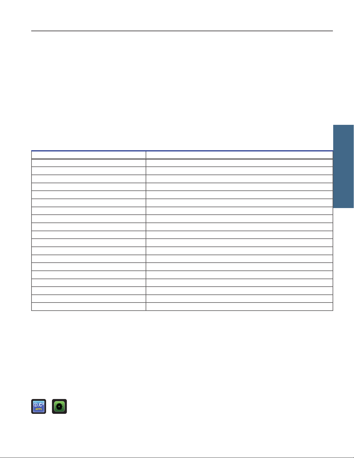
Table 1. i.Series Active Alarms
Alarm Description
Communication Failure 1 Communication lost between i.C
Communication Failure 2 Conguration le is corrupt or i.C
Communication Failure 3 Corrupt database
Compressor Probe Failure Probe not functioning properly
Compressor High T emperature Compressor temperature reading is above high temperature alarm setpoint
Control Probe Failure Probe not functioning properly
Drive Space Low SD card is approaching capacity
Drive Space Full SD card is full
Door Open Door is open beyond user-specied duration
Inverter Communication Failure Communication is lost between the i.C
Low Battery Back-up battery voltage is low
No Battery Back-up battery voltage is decient
Power Failure Power to the unit has been disrupted
Primary Monitor Probe Failure Probe not functioning properly
Primary Probe High Temperature Primary monitor probe reading is above high temperature alarm setpoint
Primary Probe Low Temperature Primary monitor probe reading is below low temperature alarm setpoint
Secondary Monitor Probe Failure (if installed) Probe not functioning properly
Secondary Probe High Temperature (if installed) Secondary monitor probe reading is above high temperature alarm setpoint
Secondary Probe Low Temperature (if installed) Secondary monitor probe reading is below low temperature alarm setpoint
3
display board and control board
3
is unable to access the conguration le
3
control board and the VCC inverter
i.Series
3.6 Mute Active Alarms
Audible alarms may be temporarily muted by touching the Mute icon. The delay duration can be set and changed by selecting
Sound Settings from the Settings screen. The duration may be set to any value from 1 - 60 minutes. The delay time remaining
will be displayed in the bottom right corner of the icon. If the alarm is still active after the mute delay has ended, the audible alarm
will sound.
Unmuted Muted
> > Enter the Settings password. Scroll down to select Sound Settings. Touch minus (-) or plus (+) on spin box to set
the mute duration.
360414/B 11
Page 15
Helmer Scientic i.Series
® -
Horizon Series
™
Refrigerator Instructions for Use
3.7 Light Operation (if installed)
Press Light Icon to turn LED lights ON or OFF.
Auto ON/OFF feature can be congured in Settings.
Light ON/OFF
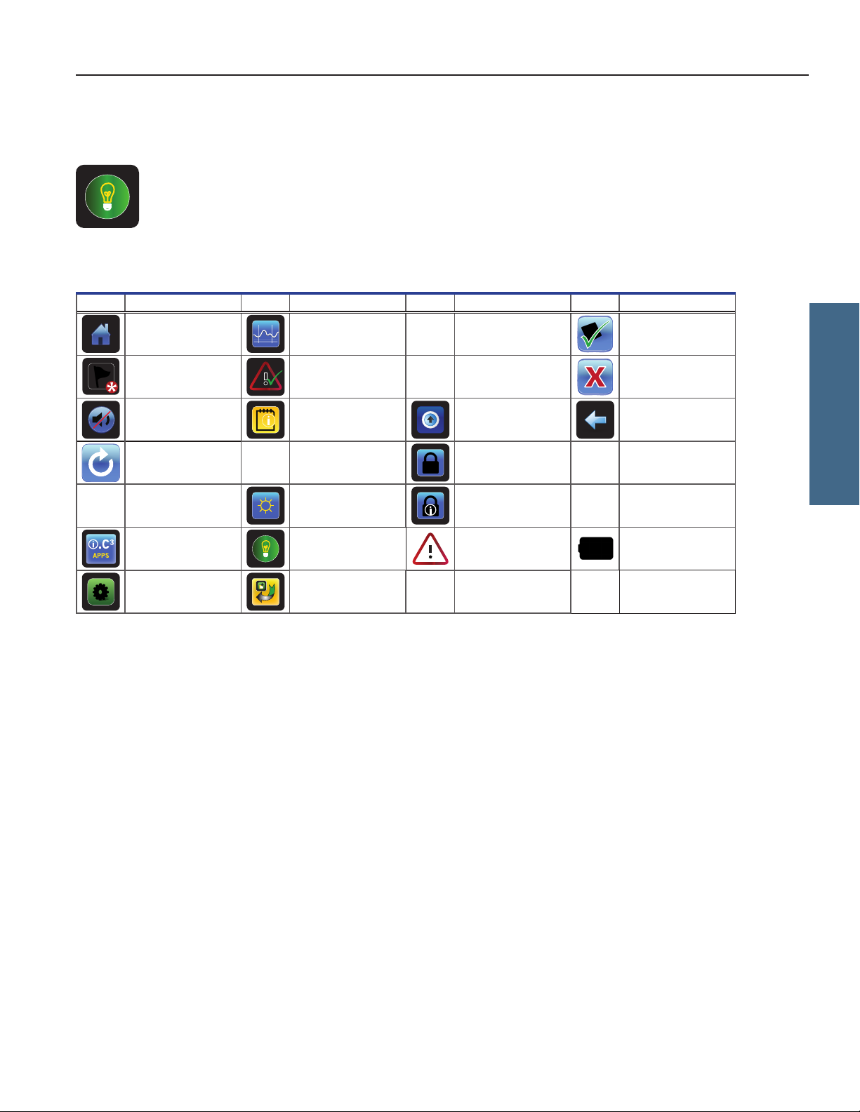
Table 2. Application Icons
Icon
Description
Home Temperature Graph CSV Download Save
Icon
Description
Icon
Description Icon Description
Event Log Alarm T est PDF Download Cancel
Mute Information Logs Upload Back Arrow
Reset
Zoom Information Display Brightness Access Log
i.C³ Applications Light On/O Alarm Conditions Battery Power
Settings Icon Transfer Cancel Test
Contact Information/
Contact Helmer
Access Control Scroll
Temperature Graph
Forward/Back
i.Series
360414/B 12
Page 16

Helmer Scientic i.Series
® -
Horizon Series
™
Refrigerator Instructions for Use
4 Min/Max Temperature Monitoring
The Min/Max temperature display provides the highest and lowest Primary Monitor probe temperature reading since the last
system reset (power-on event) or manually-initiated reset. Touch the Reset icon to the right of the display to manually reset.
Notes
• The Min/Max temperature display can be turned on or o through Display Settings.
• Once the time reaches the maximum display of 999 hours and 60 minutes, the message will display “>999:60”, but
minimum and maximum temperatures will continue to be tracked.
i.Series
360414/B 13
Page 17

Helmer Scientic i.Series
® -
Horizon Series
™
Refrigerator Instructions for Use
5 i.Series® Access Control (Optional)
Allows user-specic secure access to the refrigerator.
Notes
• During a power failure, the optional Access Control lock will remain locked until battery power is depleted or until the
back-up battery key switch is switched OFF.
• Switching the back-up battery key switch OFF will disable the monitoring system during a power failure.
• During a power failure, switch the battery back-up switch OFF and use the mechanical door key to provide secure
storage for refrigerator contents.
• Refer to i.C3 User Guide for complete information regarding Access Control.
5.1 Setup
Congure and manage user-specic accounts to allow controlled access to the refrigerator.
> > Access Setup
Access Control Setup password screen Access Control Setup screen
Enter the supervisor PIN to set up Access Control and follow the on-screen prompts to set up users.
Notes
• Initial factory supervisor PIN = 5625
• The supervisor PIN cannot be deleted, and should be changed to prevent unauthorized user ID setup. The supervisor
PIN does not allow access to the unit. At least one user ID must be set up to gain access to the unit.
5.2 Open Refrigerator with Access Control
i.Series
Access Control keypad
Enter a valid PIN using the keypad.
360414/B 14
Page 18

Helmer Scientic i.Series
® -
Horizon Series
™
Refrigerator Instructions for Use
6 Horizon Series™ Operation
6.1 Initial Power-Up
1. Plug the power cord into a grounded outlet that meets the electrical requirements on the product specication label.
2. Switch the AC ON/OFF switch ON.
3. Install 9 V back-up battery provided (undercounter battery located in literature box; upright battery located on top of unit).
4. Switch the Alarm ON/OFF key switch to ON.
5. Press Down Arrow (Mute) if high temperature alarm sounds.
Notes
• For models equipped with optional Access Control, switch the back-up battery key switch ON.
• During a power failure, the back-up battery continues to provide power to the optional Access Control lock (if equipped).
If the back-up battery is not functioning, the optional Access Control lock will not secure the door.
• If an alarm condition other than High Temperature occurs, refer to the service manual for troubleshooting.
MODE Button
CONTROL and
Door Open Lamp
High and Low
Temp Lamps
Temperature
Unit Indicator
LED Display
MONITOR Lamps
UP and DOWN Arrows
SET Button
Horizon Series™ temperature monitor and control interface
6.2 Display Minimum and Maximum Monitor Temperature Recordings
Note
This feature only applies to the Primary Monitor probe.
The minimum and maximum recording feature allows the user to view a minimum temperature occurrence and a maximum
temperature occurrence within a given period of time. The timer provides a time reference in which those temperatures occurred.
View minimum temperature recording
1. Press and hold the Down Arrow button for 1 second and listen for a single beep.
2. The display will alternate between LO and a valid temperature value ve (5) times followed by a single beep to indicate
exit back to the temperature display.
View maximum temperature recording
1. Press and hold the Up Arrow button for 1 second and listen for a single beep.
2. The display will alternate between HI and a valid temperature value ve (5) times followed by a single beep to indicate
exit back to the temperature display.
Horizon Series
360414/B 15
Page 19

Helmer Scientic i.Series
® -
Horizon Series
™
Refrigerator Instructions for Use
View recorded temperature timer
Notes
• The timer denotes the period of time that has elapsed. It does not display the time at which a minimum or maximum
temperature occurred.
• The maximum period of time the timer can record is 99:59 (99 hours and 59 minutes).
1. Press and hold either the Up or Down Arrow button for 1 second. or
2. While the display is ashing the HI or LO value, press and hold the SET button for 1 second.
3. The display will alternate ve (5) times between CLr and a value representing the number of hours and minutes that
have elapsed since the last recording (example: 12:47 would represent 12 hours and 47 minutes). A
single beep will
follow to indicate exit back to temperature display.
Clear minimum and maximum temperature recordings
1. Press and hold either the Up or Down Arrow button for 1 second. or
2. While the display is ashing the HI or LO value, press and hold the SET button for 1 second and listen for a single beep.
3. While the display is ashing the elapsed time since last reset, press and hold the SET button for 2 seconds. CLr will be
displayed followed by a series of 3 beeps to indicate exit back to the temperature display.
Notes
The minimum and maximum temperature and timer will reset when:
• the unit is powered o and battery back-up is not engaged, or
• after 99 hours and 59 minutes have elapsed.
6.3 Change Temperature Setpoint
Note
Default setpoint is 4.0 °C for HBR and HLR models; 5.0 °C for HPR models.
1. Press and release SEL to change to Control mode. The CONTROL lamp will illuminate.
2. Press and hold SET to display the current setpoint temperature.
3. Hold SET and press the Up or Down Arrow as necessary to set the desired setpoint value.
4. Release all buttons; the setpoint is changed.
5. Press and release SEL to return to Monitor mode. The MONITOR lamp will illuminate.
Horizon Series
360414/B 16
Page 20
Helmer Scientic i.Series
® -
Horizon Series
™
Refrigerator Instructions for Use
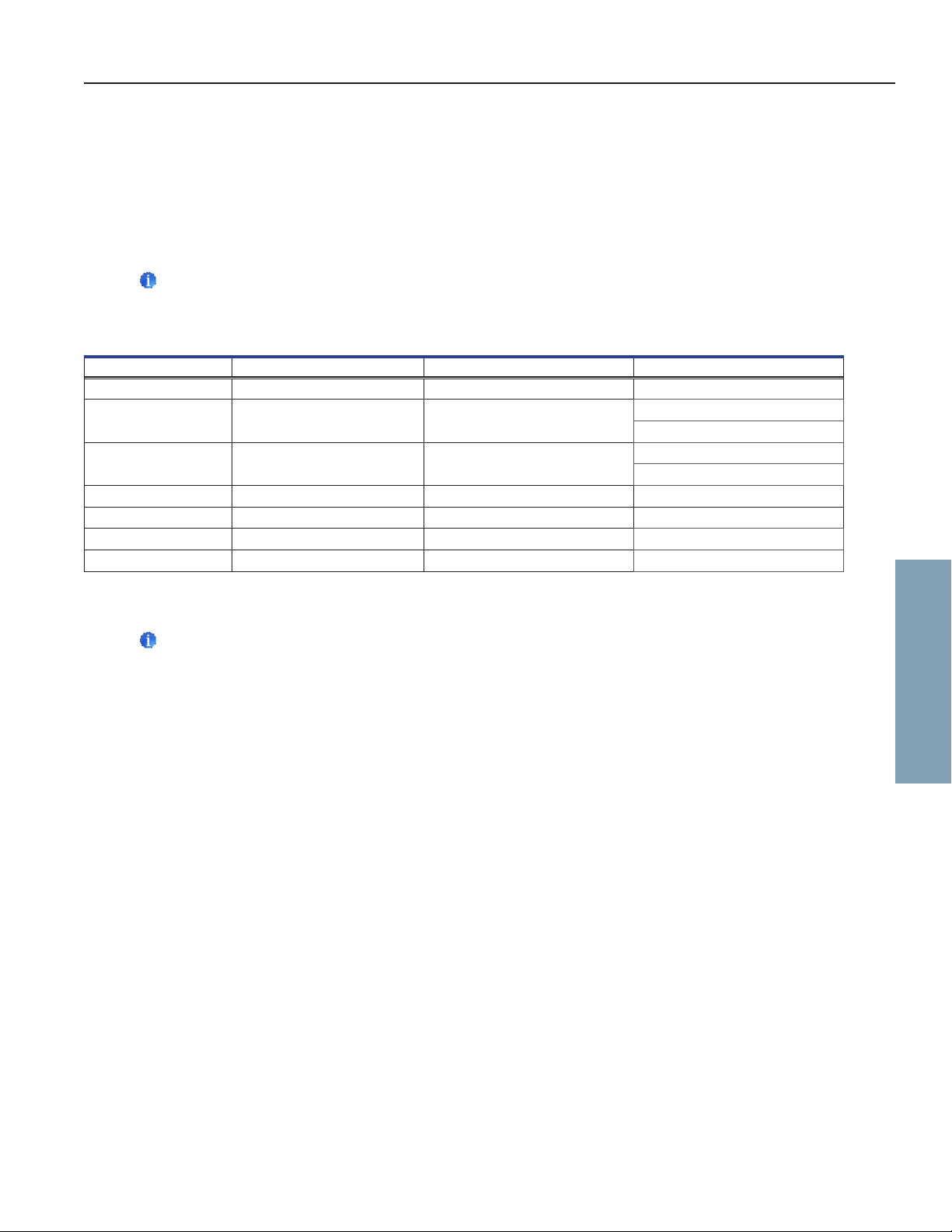
6.4 Set Parameter Values
1. Press and hold the Up and Down Arrows simultaneously for 3 seconds to enter program mode.
2. The LED Display will show .C or .F to indicate Celsius or Fahrenheit.
3. Press and release SEL button to scroll through the parameters.
4. Once the desired parameter is selected, press and hold the SET button while pressing the Up or Down Arrow to select
the desired value.
5. Release SET button. The new setting is saved.
6. Press and hold the Up and Down Arrows simultaneously for 3 seconds to exit program mode.
Note
Contact Helmer Technical Service to set Rail Limit values.
Table 3. Parameter Values
Parameter Visual Indicator Range Default
Celsius or Fahrenheit None ˚C, ˚F ˚C
High Temperature MONITOR Lamp & HIGH Lamp -40.0 to 25.0 (˚C) -40 to 77 (˚F) 5.5 °C
Low Temperature MONITOR Lamp & LOW Lamp -40.0 to 25.0 (˚C) -40 to 77 (˚F) 1.5 °C (HBR models)
Monitor Offset MONITOR Lamp -10.0 to 10.0 (˚C) -18 to 18 (˚F) Varies
Control Offset CONTROL Lamp -10.0 to 10.0 (˚C) -18 to 18 (˚F) Varies
Upper Rail Limit CONTROL Lamp & HIGH Lamp 0.1 to 10.0 (˚C); 1 to 18 (˚F) 0.7 °C
Lower Rail Limit CONTROL Lamp & LOW Lamp 0.1 to 10.0 (˚C); 1 to 18 (˚F) -0.7 °C
(HBR and HLR models)
6.5 °C (HPR models)
2.0 °C (HLR and HPR models)
6.5 Set Temperature Units
Note
If temperature units are changed, the temperature setpoints, osets and alarm settings must be recalibrated.
1. Press and hold the Up and Down Arrows simultaneously for 3 seconds to enter program mode.
2. The LED Display will show ˚C or ˚F to indicate Celsius or Fahrenheit.
3. Press and hold the SET button while pressing the Up or Down Arrow to select the desired temperature unit.
4. Release SET button. The new setting is saved.
5. Press and hold the Up and Down Arrows simultaneously for 3 seconds to exit program mode.
6.6 Set Alarm Setpoints (Parameters)
1. Press and hold the Up and Down Arrows simultaneously for 3 seconds to enter program mode.
2. The LED Display will show .C or .F to indicate Celsius or Fahrenheit.
3. Press MODE until HIGH TEMP or LOW TEMP and MONITOR lamps ash.
4. Hold SET, then press Up or Down Arrow to change the setpoint.
5. Release SET button. The new setting is saved.
6. Press and hold Up and Down Arrows simultaneously for 3 seconds to exit program mode.
Horizon Series
360414/B 17
Page 21
Helmer Scientic i.Series
® -
Horizon Series
™
Refrigerator Instructions for Use
6.7 TemperatureCalibrationOsets
Temperature calibration osets indicate an acceptable margin of error between the actual temperature value and the desired
temperature value.
Monitor Oset
♦ Value is factory-set to match a calibrated reference thermometer.
♦ Refer to the service manual for instructions regarding changing the Monitor Oset.
Control Sensor Oset and Hysteresis
The control sensor aects the reading of the control probe temperature and therefore the actual temperature of the
refrigerator. This should not be adjusted from the original setting unless directed by Helmer Technical Service.
The Upper and Lower Rail Limits help control the refrigeration based on the control probe temperature reading and the set
point. These limit values should not be changed from the default setting unless directed by Helmer Technical Service.
NOTICE
Control Sensor Oset and Rail Limits are factory-preset and should not be changed. Contact Helmer T
echnical Service for
instructions regarding changing these values.
6.8 Active Alarms
The controller displays temperature and alarm information.
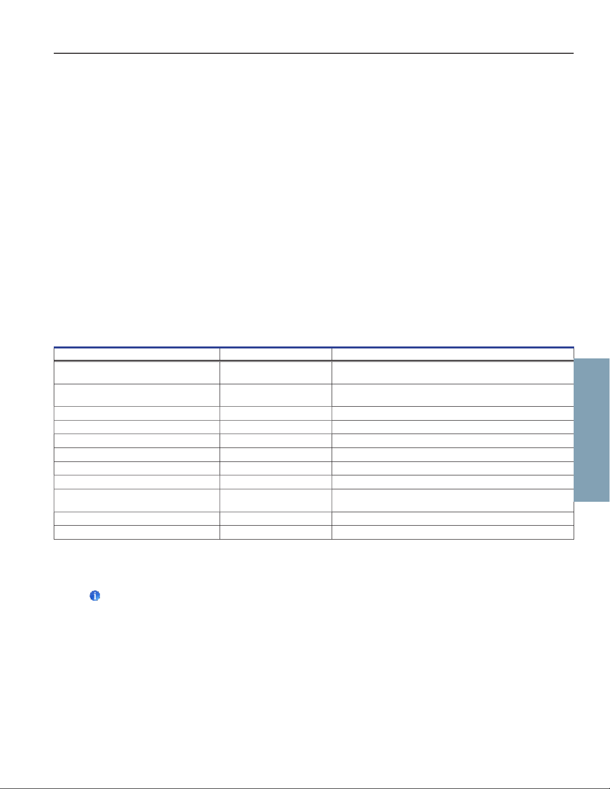
Table 4. Horizon Series Active Alarms
Alarm Visual Indicator Description
High Temperature HIGH TEMP lamp ashes Chamber temperature reading is above high temperature
alarm setpoint
Low Temperature LOW TEMP lamp ashes Chamber temperature reading is below low temperature
alarm setpoint
Display/Control Board Communication Error Er04 Display board fails to communicate with the control board
Control Board to Compressor Inverter Error Er05 Communication loss from control board to compressor inverter
Power Failure ”PoFF” appears on display Power to unit has been disrupted
Primary Monitor Probe Failure (RTD1) Er01 Probe not functioning properly
Control Probe Failure (RTD2) Er02 Probe not functioning properly
No Battery Er06 Battery voltage is low
Conguration Error Er07 Indicates that an EEPROM reading was corrupted or dip switch
settings on the control board have changed since last power-up
Door Open < 3 min. DOOR ALARM lamp lights Door is open (less than three minutes)
Door Open > 3 min. DOOR ALARM lamp ashes Door has been open 3 minutes or longer*
*Audible alarm will sound after door is open for 3 minutes.
6.9 Mute and Disable Audible Alarms
Note
Muting audible alarms does not disable alarm lamps or signals sent through the remote alarm interface.
Horizon Series
♦ Press Down Arrow (Mute) to mute audible alarms.
♦ To disable all audible alarms, insert the key in the Alarm Disable switch and turn.
6.10 Light Operation
The light switch is located on the monitoring and control panel and controls the LED light within the chamber.
360414/B 18
Page 22

Helmer Scientic i.Series
® -
Horizon Series
™
Refrigerator Instructions for Use
7 Horizon Series™ Access Control (Optional)
Allows user-specic secure access to the refrigerator.
Notes
• During a power failure, the optional Access Control lock will remain locked until battery power is depleted or until the
back-up battery key switch is switched OFF.
• During a power failure, switch the battery back-up switch OFF and use the mechanical door key to provide secure
storage for refrigerator contents.
• Refer to Horizon Series Access Control manual for complete information.
7.1 Setup
The Access Control keypad was programmed at the factory with a master code (0000). The master code is used to program the
keypad and enter user codes.
Note
The master code should be changed to prevent unauthorized user code setup.
Enter unique user codes for up to 100 users. Each user code is stored with a specic record location number. Keep a log of the
location numbers and user codes with users’ names.
Add User Code
1. Enter the master code followed by the * (asterisk) key
2. Press 1 to initiate user code programming function
3. Enter the location number (00 - 99)
4. Enter the user code (4 - 8 digit number) followed by the # (pound) key
5. Press * (asterisk) to save changes and return to normal operation
Horizon Series
Delete User Code
1. Enter the master code followed by the * (asterisk) key
2. Press 1 to initiate delete user code programming function
3. Enter the location number (00 - 99) followed by the # (pound) key
4. Press * (asterisk) to save changes and return to normal operation
Open Refrigerator with Access Control
1. Enter the user code
2. Press # (pound) key
360414/B 19
Page 23
Helmer Scientic i.Series
® -
Horizon Series
™
Refrigerator Instructions for Use
8 ProductSpecications
8.1 Operating Standards
These units are designed to operate under the following environmental conditions:
♦ Indoor use only
♦ Altitude (maximum): 2000 m (120,125, 245, and 256 models); 3000 m (105 and 113 models)
♦ Ambient temperature range: 15 °C to 32 °C (59°F to 90°F)
♦ Relative humidity (maximum for ambient temperature): 80% for temperatures up to 31 °C; 76% at 32 °C
♦ Temperature control range: 2 °C to 10 °C (35°F to 50°F)
♦ Overvoltage Category II
♦ Pollution Degree 2
♦ RF Emissions: Group 1 - Class A
♦ EMC Environment: Basic
♦ Sound level is less than 70 dB(A)
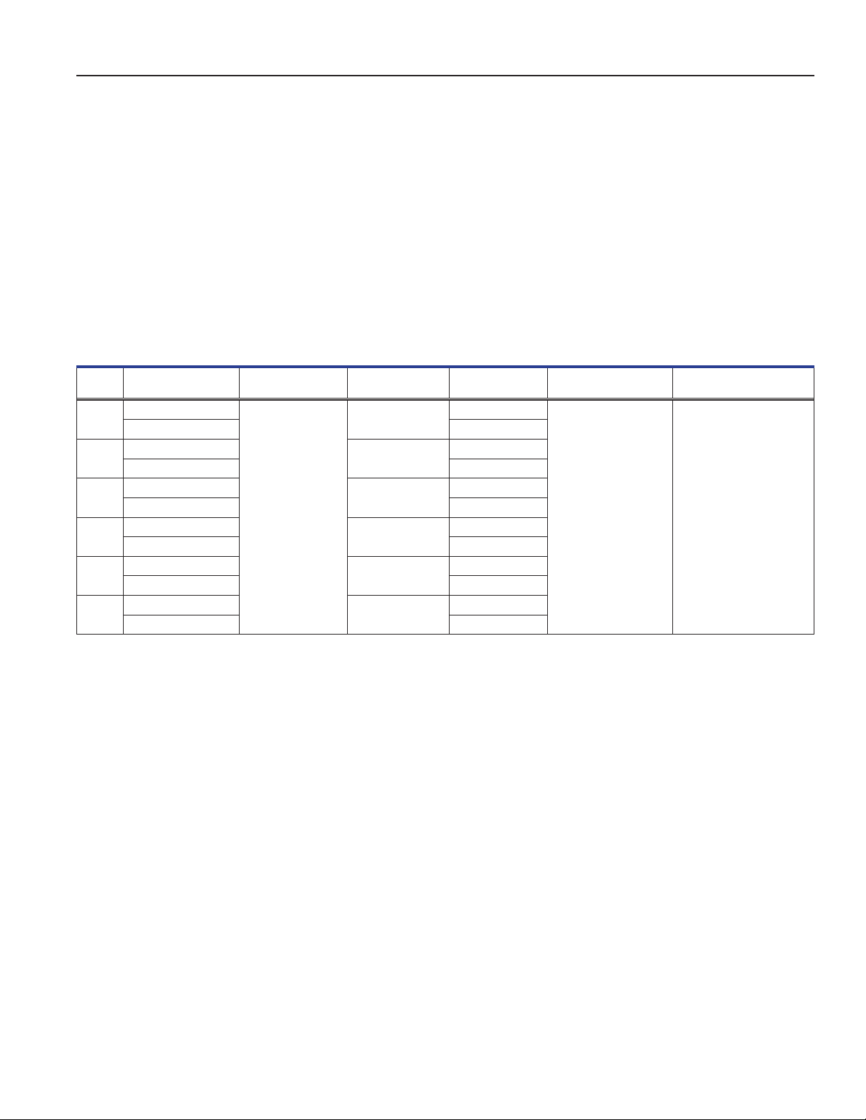
Table5.ElectricalSpecications(Laboratory,BloodBank,andPharmacy)
Model
105
113
120
125
245
256
* Amperage values are subject to change. Refer to the product specication label on your unit for current values.
Input Voltage &
Frequency
115V 60 Hz
220-240V 50/60 Hz 0.85A
115V 60 Hz
220-240V 50/60 Hz 1.12A
115V 60 Hz
220-240V 50/60 Hz 1.55A
115V 60 Hz
220-240V 50/60 Hz 1.55A
115V 60 Hz
220-240V 50/60 Hz 2.5A
115V 60 Hz
220-240V 50/60 Hz 2.5A
Voltage Tolerance Circuit Breakers
4A quantity 2
4A quantity 2
quantity 2
7A
±10%
7A
quantity 2
7A quantity 2
7A quantity 2
Current Draw
1.4A
2.3A
2.8A
2.8A
4.3A
4.3A
electrical requirements
Notes
• The interface on the remote alarm monitoring system is intended for connection to the end user’s central alarm
system(s) that uses normally-open or normally-closed dry contacts.
• If an external power supply exceeding 33V (RMS) or 30V (DC) is connected to the remote alarm monitoring system’s
circuit, the remote alarm will not function properly or may be damaged.
Power Source Remote Alarm Capacity
Grounded outlet,
meeting national
electric code (NEC)
in the U.S. and local
in all locations.
115V or 230V:
1A at 33V (AC) RMS or
30V (DC)
360414/B 20
Page 24
Helmer Scientic i.Series
® -
Horizon Series
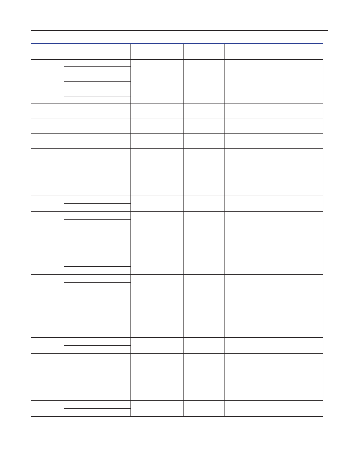
Table6.RefrigeratorSpecications
™
Refrigerator Instructions for Use
Model Voltage Code Amps
iLR105-GX
iBR105-GX
iPR105-GX
HLR105-GX
HBR105-GX
HPR105-GX
iLR113-GX
iBR113-GX
iPR113-GX
HLR113-GX
HBR113-GX
HPR113-GX
iLR120-GX
iBR120-GX
iPR120-GX
HLR120-GX
HBR120-GX
HPR120-GX
iLR125-GX
iBR125-GX
iPR125-GX
HLR125-GX
HBR125-GX
115V 60 Hz 1.4
220-240V 50/60 Hz 0.85
115V 60 Hz 1.4
220-240V 50/60 Hz 0.85
115V 60 Hz 1.4
220-240V 50/60 Hz 0.85
115V 60 Hz 1.4
220-240V 50/60 Hz 0.85
115V 60 Hz 1.4
220-240V 50/60 Hz 0.85
115V 60 Hz 1.4
220-240V 50/60 Hz 0.85
115V 60 Hz 2.3
220-240V 50/60 Hz 1.12
115V 60 Hz 2.3
220-240V 50/60 Hz 1.12
115V 60 Hz 2.3
220-240V 50/60 Hz 1.12
115V 60 Hz 2.3
220-240V 50/60 Hz 1.12
115V 60 Hz 2.3
220-240V 50/60 Hz 1.12
115V 60 Hz 2.3
220-240V 50/60 Hz 1.12
115V 60 Hz 2.8
220-240V 50/60 Hz 1.55
115V 60 Hz 2.8
220-240V 50/60 Hz 1.55
115V 60 Hz 2.8
220-240V 50/60 Hz 1.55
115V 60 Hz 2.8
220-240V 50/60 Hz 1.55
115V 60 Hz 2.8
220-240V 50/60 Hz 1.55
115V 60 Hz 2.8
220-240V 50/60 Hz 1.55
115V 60 Hz 2.8
220-240V 50/60 Hz 1.55
115V 60 Hz 2.8
220-240V 50/60 Hz 1.55
115V 60 Hz 2.8
220-240V 50/60 Hz 1.55
115V 60 Hz 2.8
220-240V 50/60 Hz 1.55
115V 60 Hz 2.8
220-240V 50/60 Hz 1.55
Cu. Ft/
Liters Cabinet Door
5.3
(150)
5.3
(150)
5.3
(150)
5.3
(150)
5.3
(150)
5.3
(150)
13
(377)
13
(377)
13
(377)
13
(377)
13
(377)
13
(377)
20
(572)
20
(572)
20
(572)
20
(572)
20
(572)
20
(572)
25
(714)
25
(714)
25
(714)
25
(714)
25
(714)
Undercounter
Undercounter
Undercounter
Undercounter
Undercounter
Undercounter
Slimline
Slimline
Slimline
Slimline
Slimline
Slimline
Upright
Upright
Upright
Upright
Upright
Upright
Upright
Upright
Upright
Upright
Upright
Single hinged
solid
Single hinged
solid
Single hinged
solid
Single hinged
solid
Single hinged
solid
Single hinged
solid
Single hinged
glass
Single hinged
glass
Single hinged
glass
Single hinged
glass
Single hinged
glass
Single hinged
glass
Single hinged
glass
Single hinged
glass
Single hinged
glass
Single hinged
glass
Single hinged
glass
Single hinged
glass
Single hinged
glass
Single hinged
glass
Single hinged
glass
Single hinged
glass
Single hinged
glass
Dimensions W x H x D in. (mm) Net Wt.
Exterior*
24.3 x 31.9 x
(616 x
24.3 x 31.9 x
(616 x
24.3 x 31.9 x
(616 x
24.3 x 31.9 x
(616 x
24.3 x 31.9 x
(616 x
24.3 x 31.9 x
(616p x
28.1
809 x 714)
28.1
809 x 714)
28.1
809 x 714)
27.8
809 x 705)
27.8
809 x 705)
27.8
809 x 705)
24.6 x 70.5 x 30.8
(625 x 1790 x 780)
24.6 x 70.5 x 30.8
(625 x 1790 x 780)
24.6 x 70.5 x 30.8
(625 x 1790 x 780)
24.6 x 70.5 x 30.8
(625 x 1790 x 780)
24.6 x 70.5 x 30.8
(625 x 1790 x 780)
24.6 x 70.5 x 30.8
(625 x 1790 x 780)
29.5 x 79.6 x 31.7
(748 x 2021 x 803)
29.5 x 79.6 x 31.7
(748 x 2021 x 803)
29.5 x 79.6 x 31.7
(748 x 2021 x 803)
29.5 x 78.3 x 31.7
(748 x 1989 x 803)
29.5 x 78.3 x 31.7
(748 x 1989 x 803)
29.5 x 78.3 x 31.7
(748 x 1989 x 803)
29.5 x 79.6 x 37.7
(748 x 2021 x 956)
29.5 x 79.6 x 37.7
(748 x 2021 x 956)
29.5 x 79.6 x 37.7
(748 x 2021 x 956)
29.5 x 78.3 x 37.7
(748 x 1989 x 956)
29.5 x 78.3 x 37.7
(748 x 1989 x 956)
lbs (kg)
174
(79)
186
(85)
182
(83)
174
(79)
184
(84)
182
(83)
306
(139)
342
(156)
338
(154)
306
(139)
337
(153)
338
(154)
445
(202)
507
(230)
438
(199)
442
(201)
504
(229)
487
(221)
456
(207)
535
(243)
517
(235)
453
(206)
532
(242)
360414/B 21
Page 25
Helmer Scientic i.Series
® -
Horizon Series
™
Refrigerator Instructions for Use
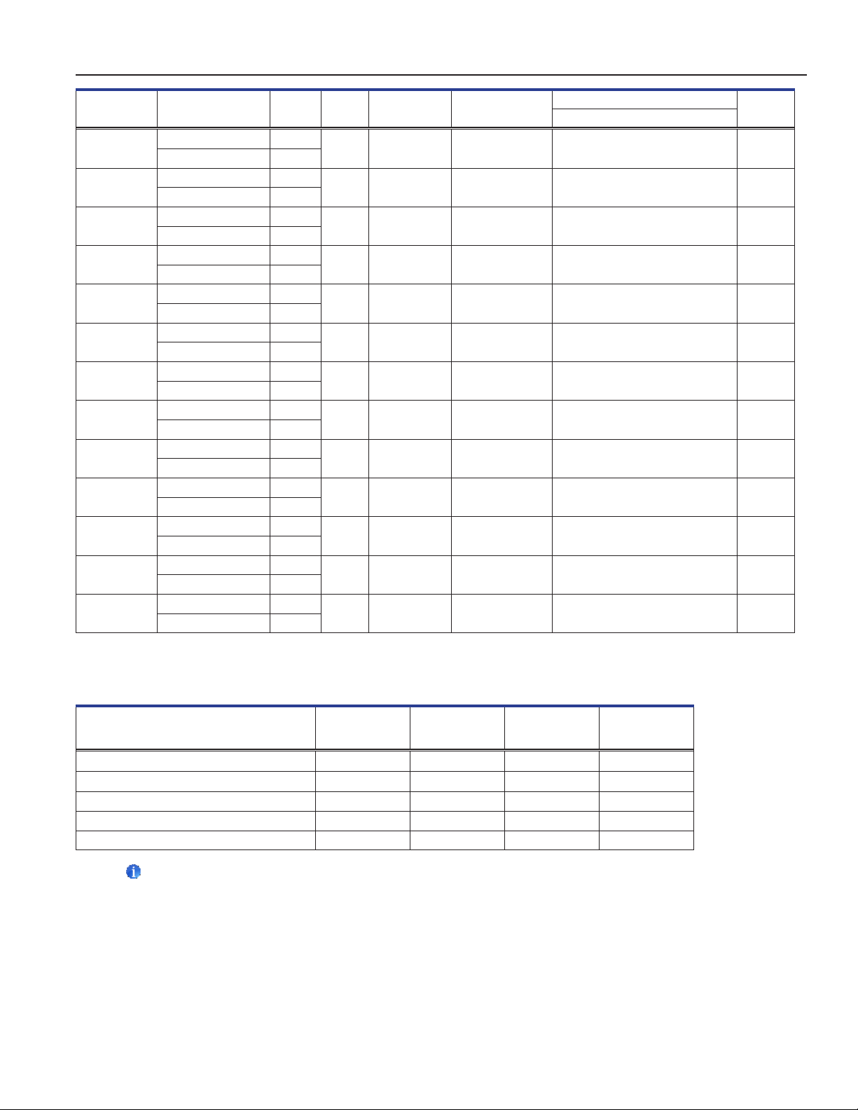
Dimensions W x H x D in. (mm) Net Wt.
Exterior*
29.5 x 78.3 x 37.7
(748 x 1989 x 956)
59.0 x 79.6 x 31.7
(1499 x 2021 x 803)
59.0 x 79.6 x 31.7
(1499 x 2021 x 803)
59.0 x 79.6 x 31.7
(1499 x 2021 x 803)
59.0 x 78.3 x 31.7
(1499 x 1989 x 803)
59.0 x 78.3 x 31.7
(1499 x 1989 x 803)
59.0 x 78.3 x 31.7
(1499 x 1989 x 803)
59.0 x 79.6 x 37.7
(1499 x 2021 x 956)
59.0 x 79.6 x 37.7
(1499 x 2021 x 956)
59.0 x 79.6 x 37.7
(1499 x 2021 x 956)
59.0 x 78.3 x 37.7
(1499 x 1989 x 956)
59.0 x 78.3 x 37.7
(1499 x 1989 x 956)
59.0 x 78.3 x 37.7
(1499 x 1989 x 956)
Model Voltage Code Amps
HPR125-GX
iLR245-GX
iBR245-GX
iPR245-GX
HLR245-GX
HBR245-GX
HPR245-GX
iLR256-GX
iBR256-GX
iPR256-GX
HLR256-GX
HBR256-GX
HPR256-GX
115V 60 Hz 2.8 25
220-240V 50/60 Hz 1.55
115V 60 Hz 4.3
220-240V 50/60 Hz 2.5
115V 60 Hz 4.3
220-240V 50/60 Hz 2.5
115V 60 Hz 4.3
220-240V 50/60 Hz 2.5
115V 60 Hz 4.3
220-240V 50/60 Hz 2.5
115V 60 Hz 4.3
220-240V 50/60 Hz 2.5
115V 60 Hz 4.3
220-240V 50/60 Hz 2.5
115V 60 Hz 4.3
220-240V 50/60 Hz 2.5
115V 60 Hz 4.3
220-240V 50/60 Hz 2.5
115V 60 Hz 4.3
220-240V 50/60 Hz 2.5
115V 60 Hz 4.3
220-240V 50/60 Hz 2.5
115V 60 Hz 4.3
220-240V 50/60 Hz 2.5
115V 60 Hz 4.3
220-240V 50/60 Hz 2.5
Cu. Ft/
Liters Cabinet Door
(714)
45
(1271)
45
(1271)
45
(1271)
45
(1271)
45
(1271)
45
(1271)
56
(1586)
56
(1586)
56
(1586)
56
(1586)
56
(1586)
56
(1586)
Upright
Upright
Upright
Upright
Upright
Upright
Upright
Upright
Upright
Upright
Upright
Upright
Upright
Single hinged
glass
Double hinged
glass
Double hinged
glass
Double hinged
glass
Double hinged
glass
Double hinged
glass
Double hinged
glass
Double hinged
glass
Double hinged
glass
Double hinged
glass
Double hinged
glass
Double hinged
glass
Double hinged
glass
* 105 models - Exterior dimensions include handle and leveling feet at lowest level.
** 113, 120, 125, 245, 256 models - Exterior dimensions include casters, door handle and electrical box.
lbs (kg)
514
(234)
667
(303)
809
(367)
775
(352)
667
(303)
808
(367)
774
(352)
703
(319)
863
(392)
827
(376)
693
(315)
853
(387)
817
(371)
Table7.StorageComponentSpecications
Storage Component
Net weight
lbs (kg)
105 models
Net weight
lbs (kg)
113 models
Net weight
lbs (kg)
120/245 models
Net weight
lbs (kg)
125/256 models
Shelf 6 (3) 6 (3) 7 (3.2) 8 (3.6)
Ventilated Drawer 10 (5) 8.2 (3.7) 11 (5) 13.5 (6.1)
Liquid-tight Stainless Drawer
Liquid-tight Stainless Drawer
(i.Series) 12 (6) 12.1 (5.5) 14.2 (6.5) 17.2 (7.8)
(Horizon Series) 11 (5) 11.8 (5.4) 13.7 (6.2) 16.6 (7.5)
Stainless Drawer with Locking Lid 15 (7) 13.6 (6.2) 15.5 (7) 19 (8.6)
Notes
• Amperage values listed represent the highest current draw presented among available factory congurations for
each model Units without heated glass doors will have lower current draw.
• Maximum height added with leveling feet or casters installed is 2” (51 mm).
• Maximum load per shelf or drawer - 100 lbs (46kg).
• Net weight may vary depending on storage conguration. Weight listed in the table reects standard conguration for
each model.
360414/B 22
Page 26
Helmer Scientic i.Series
® -
Horizon Series
™
Refrigerator Instructions for Use
9 Compliance
9.1 Safety Compliance
This device complies with the requirements of directive 93/42/EEC concerning Medical Devices, as amended
by 2007/47/EC.
This product is certied to applicable UL and CSA standards by a NRTL.
This product is IECEE CB Scheme certied and complies with national dierences for safety certication beyond
IEC 61010-1-12 3rd edition.
9.2 Environmental Compliance
This device complies with the 2011/65/EU Directive for the Restriction of Hazardous Substances (RoHS).
This device falls under the scope of Directive 2102/19/EU Waste Electrical and Electronic Equipment (WEEE) .
When disposing of this product in countries aected by this directive:
♦ Do not dispose of this product as unsorted municipal waste.
♦ Collect this product separately.
♦ Use the collection and return systems available locally.
For more information on the return, recovery, or recycling of this product, contact your local distributor.
9.3 EMC Compliance
Helmer Scientic Refrigerators meet the applicable requirements of IEC61326 and EN55011 and are intended for use in the
electromagnetic environment specied in 8.1 Operating Standards. The customer or the user of these devices should assure they
are used in such environment.
This device complies with FCC Radiated and Conducted Emissions Approval to CFR47, Part 15; Class A levels
360414/B 23
Page 27

Helmer Scientic i.Series
® -
Horizon Series
™
Refrigerator Instructions for Use
360414/B 24
Page 28

Helmer Scientic
14400 Bergen Boulevard, Noblesville, IN 46060 USA
Copyright © 2020 Helmer, Inc.
360414/B
 Loading...