

Page 1
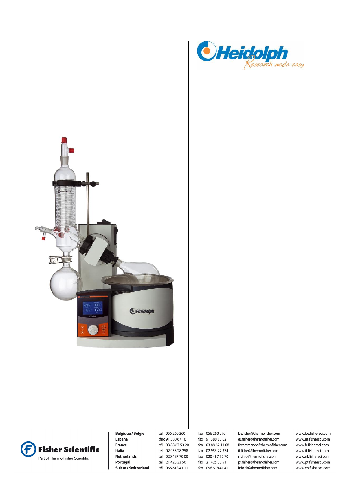
Hei-VAP Value
Hei-VAP Advantage
Operating Instructions
Page 2

Page 3

Translation of the original operating instructions.
The operating instructions must be read prior to the initial
start-up for your safety and ease of use! Follow safety instructions to prevent unnecessary accidents from occurring
associated with misuse of product!
Store for future use in a safe location!
This documentation is not subject to any modification service!
Page 4

Page 5

Table of contents
EN
Table of contents
1 About this Document .................................................................................................... 1
1.1 Versions references ........................................................................................................................... 1
1.2 About this manual .............................................................................................................................. 1
1.2.1 Reference documents ...................................................................................................................... 1
1.2.2 Icons and symbols ........................................................................................................................... 2
2 Basic safety instructions .............................................................................................. 5
2.1 General Safety Instructions .............................................................................................................. 5
2.2 Intended use ....................................................................................................................................... 5
2.3 Improper Use ...................................................................................................................................... 5
2.4 Use in explosion-prone areas ........................................................................................................... 6
2.5 Responsibilities of the operator ....................................................................................................... 6
2.6 Responsibilities of the operating personnel ................................................................................... 6
2.7 Qualifications of Personnel ............................................................................................................... 7
2.8 Safety Conscious Working ................................................................................................................ 7
2.9 Safety devices on the equipment ..................................................................................................... 7
2.10 Signs on the equipment .................................................................................................................... 8
2.11 Remaining hazards ............................................................................................................................ 8
3 Unit Description ...........................................................................................................11
4 Set-up and Start-up ......................................................................................................12
4.1 Scope of delivery ............................................................................................................................. 12
4.2 Transport .......................................................................................................................................... 14
4.2.1 Removing the transportation safety device .................................................................................... 14
4.2.2 Attaching the transportation protection device before packing ...................................................... 14
4.3 Setting up the basic unit ................................................................................................................. 15
4.4 Start-up ............................................................................................................................................. 15
4.4.1 Installing the heating bath .............................................................................................................. 15
4.4.2 Fill the heating bath ....................................................................................................................... 16
4.4.3 Offsetting the heating bath ............................................................................................................. 16
4.4.4 Heating bath set-up when using Rotacool ..................................................................................... 16
4.4.5 Connect the base unit .................................................................................................................... 17
4.4.6 Operating the lift ............................................................................................................................ 19
4.5 Assemble glassware sets ................................................................................................ ................ 19
4.5.1 Install the condenser mounting (G3-G6) ........................................................................................ 20
4.5.2 Install the vapor tube ..................................................................................................................... 21
4.5.3 Install the condenser ...................................................................................................................... 23
4.5.4 Mount the vertical condenser (G3-G6) in the condenser bracket................................................... 25
4.5.5 Install the evaporator flask ............................................................................................................. 26
4.5.6 Setting the evaporator flask inclination .......................................................................................... 27
4.5.7 Setting the immersion depth of the evaporator flask ...................................................................... 28
4.5.8 Release the evaporator flask from the vapor tube ......................................................................... 29
4.5.9 Insert the inlet tube ........................................................................................................................ 30
4.5.10 Assemble the inlet tube ................................................................................................................. 30
4.5.11 Assemble the collecting flask ......................................................................................................... 31
4.5.12 Connect the cooling medium (except G5) ...................................................................................... 31
4.5.13 Connect the vacuum ...................................................................................................................... 32
Page 6

Table of contents
EN
4.6 Feed the distilled material ............................................................................................................... 37
4.7 Ventilate manually ........................................................................................................................... 37
4.8 Assemble / connect accessories .................................................................................................... 38
4.9 Operating the control panel ............................................................................................................ 40
5 Switching on the base unit ..........................................................................................44
6 Operation of the Hei-VAP Value ..................................................................................45
6.1 Set the rotation speed ..................................................................................................................... 45
6.2 Setting the heating bath temperature ............................................................................................. 46
6.3 Error messages ................................................................................................................................ 46
7 Operation of the Hei-VAP Advantage .........................................................................47
7.1 Setting the heating bath temperature ............................................................................................. 48
7.1.1 Select heating bath medium .......................................................................................................... 48
7.1.2 Setting the heating bath temperature ............................................................................................. 49
7.2 Set the rotation speed ..................................................................................................................... 49
7.3 Calculating the boiling temperature (Hei-VAP Advantage) .......................................................... 50
7.4 Timing functions .............................................................................................................................. 51
7.4.1 Timer ............................................................................................................................................. 51
7.5 Error messages ................................................................................................................................ 51
7.6 Upgrading ......................................................................................................................................... 51
8 Errors and Troubleshooting ........................................................................................52
8.1 General errors .................................................................................................................................. 52
8.2 Additional conditions ...................................................................................................................... 53
8.3 Hei-VAP Value .................................................................................................................................. 54
8.4 Hei-VAP Advantage.......................................................................................................................... 55
9 Maintenance, cleaning, service ...................................................................................57
9.1 Maintenance ..................................................................................................................................... 57
9.1.1 Resetting the maximum temperature limiter .................................................................................. 57
9.1.2 Evacuate the heating bath ............................................................................................................. 58
9.1.3 Readjust the vacuum seal (glassware set G6)............................................................................... 58
9.2 Replacing the fuses ......................................................................................................................... 59
9.3 Cleaning ............................................................................................................................................ 60
9.4 Service .............................................................................................................................................. 60
10 Dismantling, storage, disposal ..............................................................................61
10.1 Disassembly ..................................................................................................................................... 61
10.1.1 Remove the Woulff bottle .............................................................................................................. 61
10.1.2 Disconnecting the coolant / vacuum .............................................................................................. 62
10.1.3 Remove the heating bath ............................................................................................................... 62
10.2 Storage .............................................................................................................................................. 62
10.3 Disposal ................................................................................................ ................................ ............ 62
11 Accessories, spare parts .......................................................................................63
11.1 Glass devices ................................................................................................................................... 63
11.2 Accessories ...................................................................................................................................... 67
Page 7

Table of contents
EN
12 Appendix .................................................................................................................68
12.1 Technical data .................................................................................................................................. 68
12.2 Technical data o the vacuum box Hei-VAP .................................................................................... 70
12.3 Solvent data ...................................................................................................................................... 71
12.4 EC Declaration of Conformity ......................................................................................................... 73
12.5 Warranty Statement ......................................................................................................................... 74
12.6 Declaration of non-objection .......................................................................................................... 75
Page 8

Page 9

EN
Version
Modification
1.0
07/2009
Information for the Heidolph vacuum pumps Rotavac valve control
and Rotavac valve tec, along with the Vac control automatic controller are contained in a separate operating instruction # 01-005004-80.
Information regarding the Heidolph emission condensate cooler
vacuum pumps, Rotavac vario control and Rotavac vario tec are
contained in a separate operating instruction, # 01-005-004-90-0.
Versions references
Notes regarding
this manual
Reference documents
1 About this Document
1.1 Versions references
1.2 About this manual
These instructions use icons and notes that will help simplify the process of locating
information quickly. Read the explanations regarding these notes and icons in the following section.
Please read the safety guidelines and warnings in these instructions very carefully to
ensure safe operation of the product. You will find the safety instructions in chapter 2.
Warnings may be found in the introductions throughout of the chapters and prior to instruction sections.
Heidolph Instruments GmbH & Co. KG has the copyright for images and texts.
1.2.1 Reference documents
Hei-VAP Value, Hei-VAP Advantage 1
Page 10
About this Document
EN
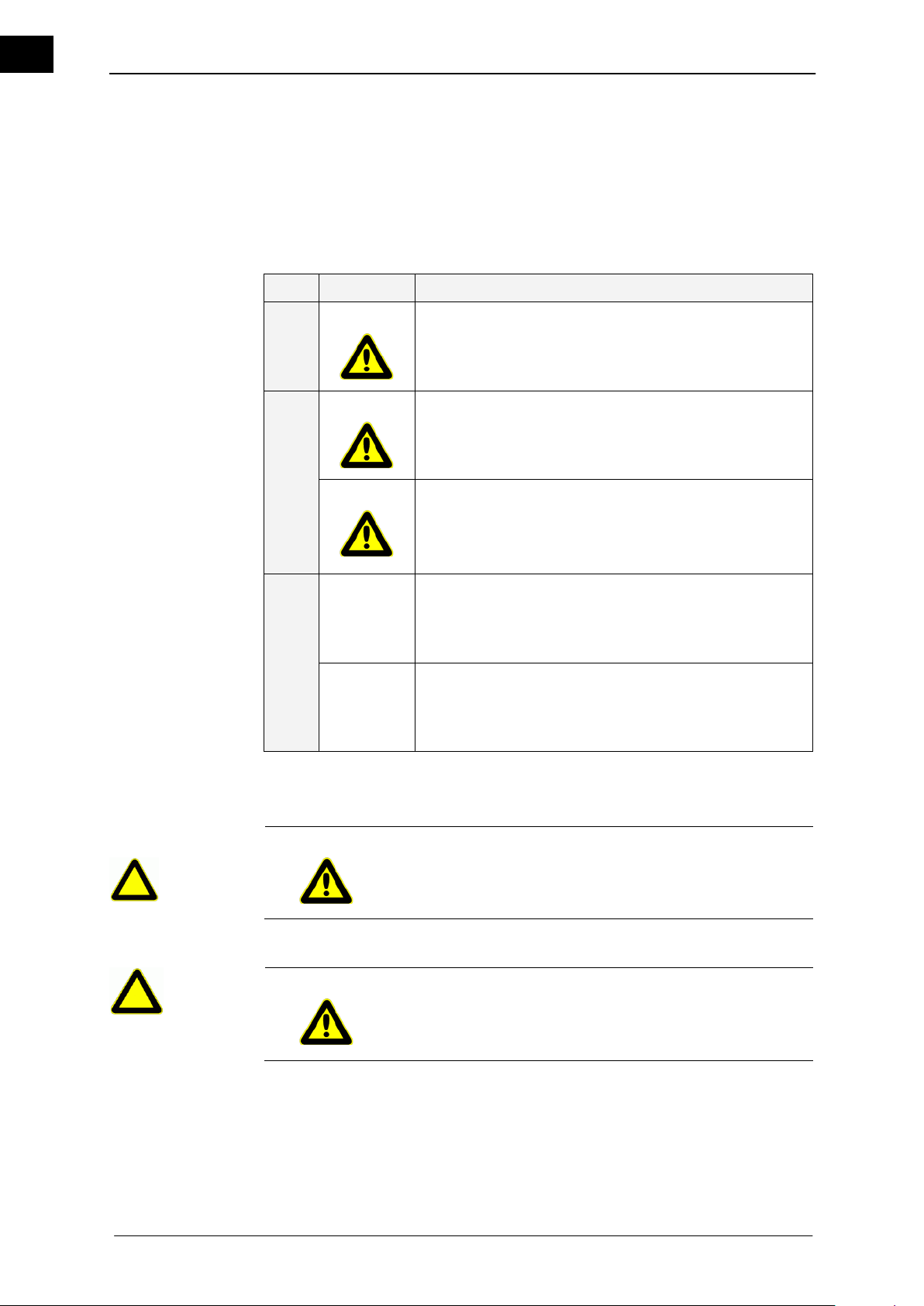
Icon
Designation
Death
RISK
This signal word must be used, if death or irreversible health
impairments may develop when the non-compliance of operator regarding the hazard warning.
Injury + property damages
WARNING
This signal word points to injuries and property damages,
including injury, accident and health risks.
WARNING
This signal word provides a reference to the risk of property
damages. In addition, there is a low risk of injuries.
No damages
CAUTION
This signal word may only be used, if health risks cannot
develop. It warns of malfunctions and is presented without an
icon, since the degree of the risk to operator is low.
IMPOR-
TANT
This signal word points to operation simplifications and crossreferences. It excludes any risks of property damages or risks
of injuries and is therefore without an icon.
RISK
The type and source of the risk is located here!
The potential consequences, if actions are not taken to prevent
the risk are listed here.
The action to prevent the risk is listed here.
WARNING
Risk of injury based on disregarding the safety icons!
Risks exist here based on disregarding the warnings on the device and in the operating instructions.
Observe warnings.
Warnings
Structure of warnings
1.2.2 Icons and symbols
Warnings
The following symbols and signal words will be continuously used in this documentation.
The combination of icon and a signal word classifies the respective safety instruction.
The symbol can vary according on the type of risk.
Table 1-1: Identification of warnings
Structure of warnings
2 Hei-VAP Value, Hei-VAP Advantage
Page 11
EN
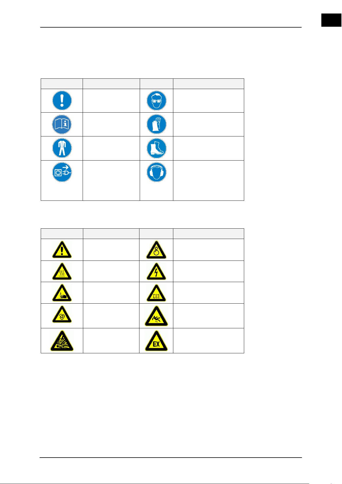
The following specific safety icons in correspondence with BGV A8 regulations will be
Icon
Explanation
Icon
Explanation
Observe
information
Use eye protection
Follow additional
information
Use hand protection
Use protective
clothing
Use foot protection
Pull the power plug
after use
Pull the power plug
prior to opening the
housing
Use ear protectors
Icon
Explanation
Icon
Explanation
Warning of a dangerous location
Warning of a risk of entanglement
Warning of a hot
surface
Warning of dangerous
electric voltage
Warning of hand
injuries
Warning of vacuum
Warning of automatic start
Warning of slippery conditions
Warning of explosive materials
Warning of explosion-risk
area
Mandatory signs
Warning signs
used at the respective text locations of these operating instructions and require special
attention depending on the combination of the signal word and icon:
Mandatory signs
Table 1-2: Icons and symbols
Warning signs
Table 1-3: Icons and symbols
Hei-VAP Value, Hei-VAP Advantage 3
Page 12
About this Document
EN
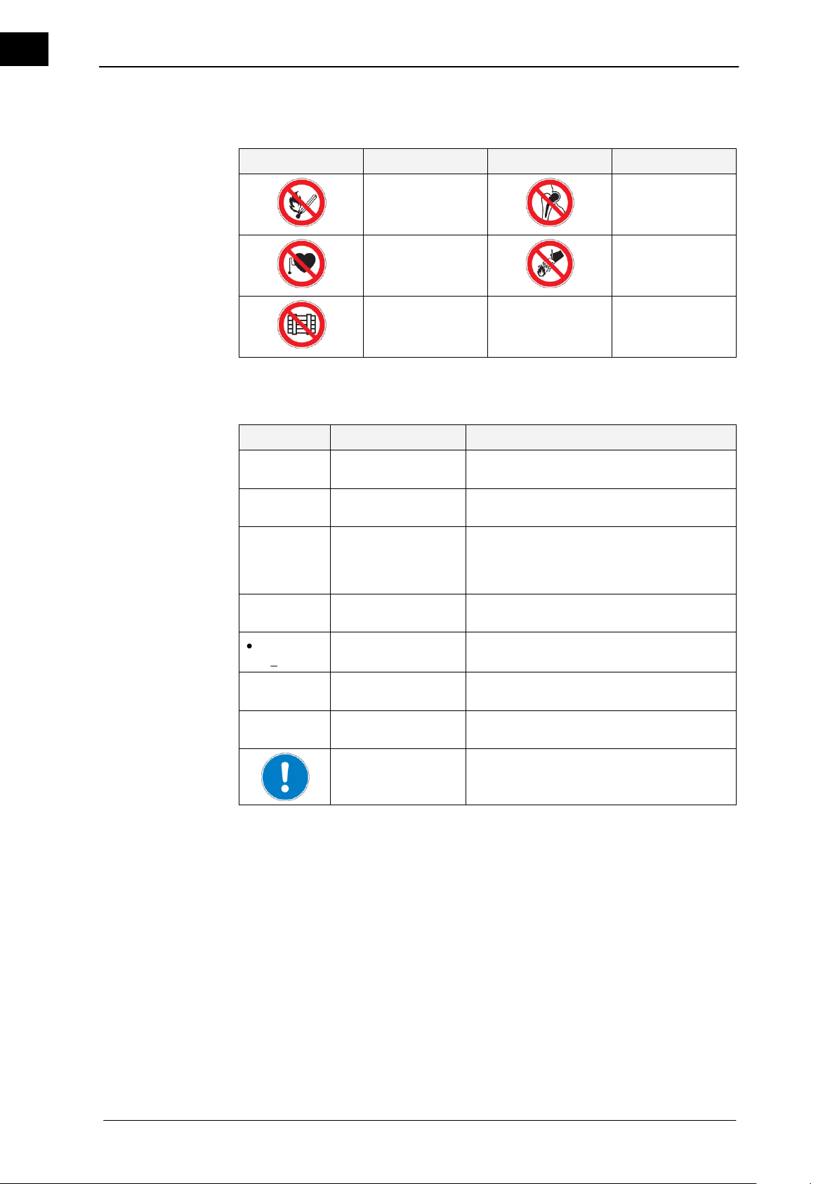
Icon
Explanation
Icon
Explanation
Fire, open flame
and smoking
prohibited
Prohibition for
people with metal
implants
Prohibition for
persons with a
pacemaker
extinguishing
with water is
prohibited
Depositing or
storing is prohibited
Icon
Use
Explanation
Prerequisite
This must be met prior to following any operating instructions
Operating instructions
You must do something here
1.
2.
Operating instructions, multi-step
Operating instructions must be performed in
the listed sequence. Deviations from the
specified sequence may result in damages of
the equipment and in accidents
Actual
result
The result of a previous activity is described
when indented
Listing,
two-tiered
Something is listed here
(see chapter
2)
Cross-reference
References for images, tables, other chapters or other instructions.
Example
Switch description
Emphasizing the description of switches/buttons
Note
Important information for the understanding
of the equipment or for improved operation
sequences
Prohibitory signs
Other icons and symbols
Images
Prohibitory signs
Table 1-4: Icons and symbols
Other icons and symbols
Table 1-5: Icons and symbols
Item numbers in the images in the text are conveyed in parentheses. If no image number
is listed, the item number refers to the image/graphic directly above the text. If the reference is made to another image/graphic, the image number is specified accordingly, i.e.
(Fig. 4-1 (11)).
4 Hei-VAP Value, Hei-VAP Advantage
Page 13

EN
2 Basic safety instructions
Basic safety instructions
General Safety Instructions
Intended use
Improper Use
The rotary evaporator is constructed according to current state of the art methods and
accepted safety regulations. However, risks still exist during the installation, operation
and maintenance of the product.
Observe safety instructions and warnings.
The basic safety instructions in this chapter are supplemented in the following chapters
of the operating instructions by concrete warnings. These warnings will precisely explain
how you must conduct yourself to protect yourself, other persons and objects from injuries or damages.
These instructions are for the following evaporator models, the Hei-VAP Value and HeiVAP Advantage rotary evaporator.
Always keep the instructions available.
Pass the instructions on to subsequent owners.
2.1 General Safety Instructions
The rotary evaporator may only be used
in an operational condition consistent with full functionality of equipment,
for the intended use described in section 2.2,
if the operator has the required safety protection and awareness to hazards,
if the instructions of these operating instructions are observed.
Malfunctions, especially those that may affect safety, must be repaired immediately!
2.2 Intended use
Hei-VAP Value and Hei-VAP Advantage are rotary evaporators for:
distillation or evaporation of solvents
purification of chemicals, substances, mixtures and preparations
processing reaction batches
drying of powder
If the equipment is used in corrosive atmospheres, the service life of the equipment
will decrease based on concentration, volumes, and frequency of exposures to these
corrosive materials, for example concentrated Hydrochloric Acid (HCl).
Any other or additional use is considered not to be in accordance with its designated
use.
The manufacturer is not liable for damage resulting from this action.
The operator alone carries the responsibility to comply with the intended use outlined
above. Observing these instructions and all references, especially safety instructions, as
well as the adherence to inspection and maintenance requirements (see chapter 9.1) are
a part of the designated use of Hei-VAP rotary evaporator.
2.3 Improper Use
Applying excess pressure to the equipment is not permitted and can result in explo-
sion of the system.
Do not use the equipment in explosion-prone areas based on local ordinance and
compliance of general laboratory equipment. The equipment is not protected against
explosions in excessively volatile and poorly ventilated environments.
Hei-VAP Value, Hei-VAP Advantage 5
Page 14

Basic safety instructions
EN
Use in explosionprone areas
Responsibilities of the operator
Responsibilities of
the operating personnel
2.4 Use in explosion-prone areas
Do not use the equipment in explosion-prone areas. The equipment is not protected
against explosions. It is not equipped with Ex or ATEX protection.
2.5 Responsibilities of the operator
Only operate the equipment in perfect condition, contact a certified Heidolph Service
representative if equipment does not meet the outlined conditions for operation.
Verify that only qualified personnel operate the equipment with the appropriate per-
sonal protective protection.
Verify that personnel have received safety instructions for working responsibly and
safely in the laboratory.
Verify that the rotary evaporator is set up in a safe and suitable location.
Verify that the basic device is only plugged to or unplugged from the heating bath if
the main switch is switched off and/or the main power supply is disconnected.
Depending on the media (chemicals) used:
Verify that the set up and the operation are only within the designated buildings with
the proper equipment for laboratories.
Verify that the rotary evaporator is only operated in conjunction with a ventilation
system (refer to DIN EN 14175 and DIN 12924).
Ventilation system:
at least 10 times the air exchange
monitored for malfunctions
2.6 Responsibilities of the operating personnel
Verify that the distillation material can be evaporated safely and that the distillation
residue is not explosive.
Verify that work using an open flame is not conducted in the surroundings of the
rotary evaporator (explosion risk).
Verify that the flow rate of < 1 m/s is guaranteed when suctioning liquids that contain
combustible materials (electrostatic charge; ignition risk).
Verify that gases of explosion group IIC do not occur in materials or chemical reac-
tions, such as hydrogen.
Verify that equipment that is an emission or radiation source (electromagnetic
waves) for the frequency range (3*1011Hz to 3*1015Hz) is not operated or attached.
Verify that equipment that is an emission or radiation source for ionizing waves or
that is within the ultrasound range is not operated or attached.
Verify that adiabatic compression and shock waves do not occur (shock wave igni-
tion).
Verify that the use of substances with the risk of an uncontrolled release of energy
associated with a rise in pressure is prohibited (exothermic reaction; self-ignition of
dust).
Verify that the glass surfaces are wiped off by using only damp cloths.
Wear suitable protective clothing for activities on the rotary evaporator a (with gog-
gles and gloves, if necessary).
Avoid pressure on the LCD screen, it is not intended to be a touch screen interface.
Verify that the maximum excess pressure of the coolant equals no more than 1 bar
in the condenser.
Verify that the basic device is only plugged to or unplugged from the heating bath if
the main switch is switched off and/or the main power supply is disconnected.
6 Hei-VAP Value, Hei-VAP Advantage
Page 15

EN
2.7 Qualifications of Personnel
This user's manual and all safety instructions must be observed,
read and understood by all personnel working on the fixture (in
particular in reference to the safety instructions).
Heating bath
Electronic and mechanical excess temperature protection
Electronic temperature control
Base unit
Clamps to secure evaporation and receiving flasks
Adjustable immersion depth of the evaporator flask
The evaporator flask may be lifted from the heating bath, if
required
Overcurrent protection on lift motors (only Hei-VAP Advan-
tage and Hei-VAP Precision)
Thermal overtemperature protection on the drive motor
Torque restrictor
Glassware set
Borosilicate glass
Screw connectors on the connections
Support rod and clamp for glassware sets G3, G5 and G6
Optional
Surlyn coating (Safecoat coating for glassware set G5) of
the glassware parts
Protective hood
Protective shield
Qualifications of Personnel
Safety Conscious Working
Safety devices on the equipment
The target group of the rotary evaporator is qualified personnel only. The rotary evaporator may only be used by personnel that have been trained in the proper operation by
qualified personnel determined in accordance with the internal safety regulations of the
facility in which the rotary evaporator is operated.
2.8 Safety Conscious Working
Heidolph Instruments is not liable for personal injuries and / or property damages caused
by an incorrect and improper usage of the rotary evaporator.
Observe the following regulations:
Laboratory guidelines
Accident prevention regulations
Ordinance on Hazardous Substances
Other generally accepted rules of safety engineering and occupational health
Local regulations
2.9 Safety devices on the equipment
Hei-VAP Value, Hei-VAP Advantage 7
Page 16
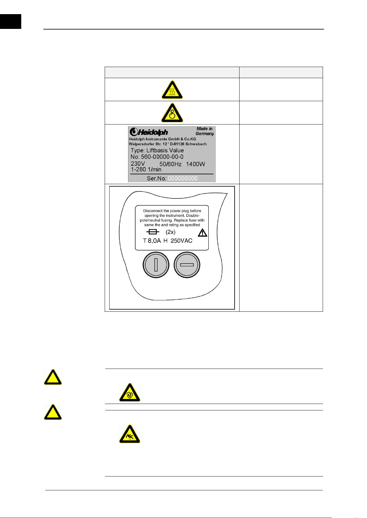
Basic safety instructions
EN
Sign
Designation
Hot surface
Risk of entanglement
Model tag
Fuse label (bottom of the device)
CAUTION
Unintentionally rotating drive!
Injuries to hands.
Verify that the rotation is displayed.
WARNING
Danger of slipping!
Risk of injury.
The floor near the machine may be dirty after the operation or
during malfunctions in the machine. Water from the bath may spill
or condensation from coolant may drip on to the floor near equipment.
Watch for contaminated areas and clean the floor, if neces-
sary.
Signs on the equipment
Remaining hazards
2.10 Signs on the equipment
Table 2-1: Signs on the equipment
2.11 Remaining hazards
Obvious residual risks may still exist, despite all precautions!
Residual risks can be reduced if the safety instructions for the intended use and the
operating instructions are all observed!
8 Hei-VAP Value, Hei-VAP Advantage
Page 17
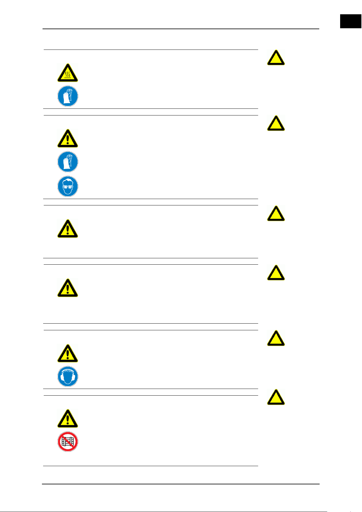
EN
WARNING
Hot surfaces!
Scalding and burns.
Let the heating bath and glass devices cool before handling.
WARNING
Glass breakage!
Cuts.
Work carefully.
WARNING
Malfunctions!
Risk of injury.
Malfunctions or operating conditions that may affect the safety of
operating personnel require a shutdown of the equipment by
disconnecting the power supplies.
A proper restoration of the normal state is required.
WARNING
Unauthorized access is prohibited!
Risk of injury.
Risks exist, if unauthorized personnel enter the danger zone of
the evaporator.
The operator has to ensure that unauthorized persons (e.g.
visitors) do not have any access to dangerous areas (service
area, protected areas).
WARNING
Risk of injury from operational noise!
Hearing impairment from the continuous sound pressure level of
the equipment may occur.
Protect against noise-induced hearing loss with ear protec-
tion.
DANGER
Disregarding the danger, work and service area!
There are risks due to electrical and mechanical energies, as well
as specific residual risks.
Guarantee a safe distance of 800 mm around the evaporator
components.
Do not deposit or store anything within the work and service area.
Accessories, chemicals or tools must be stored so that no risks
arise for personnel.
Hei-VAP Value, Hei-VAP Advantage 9
Page 18
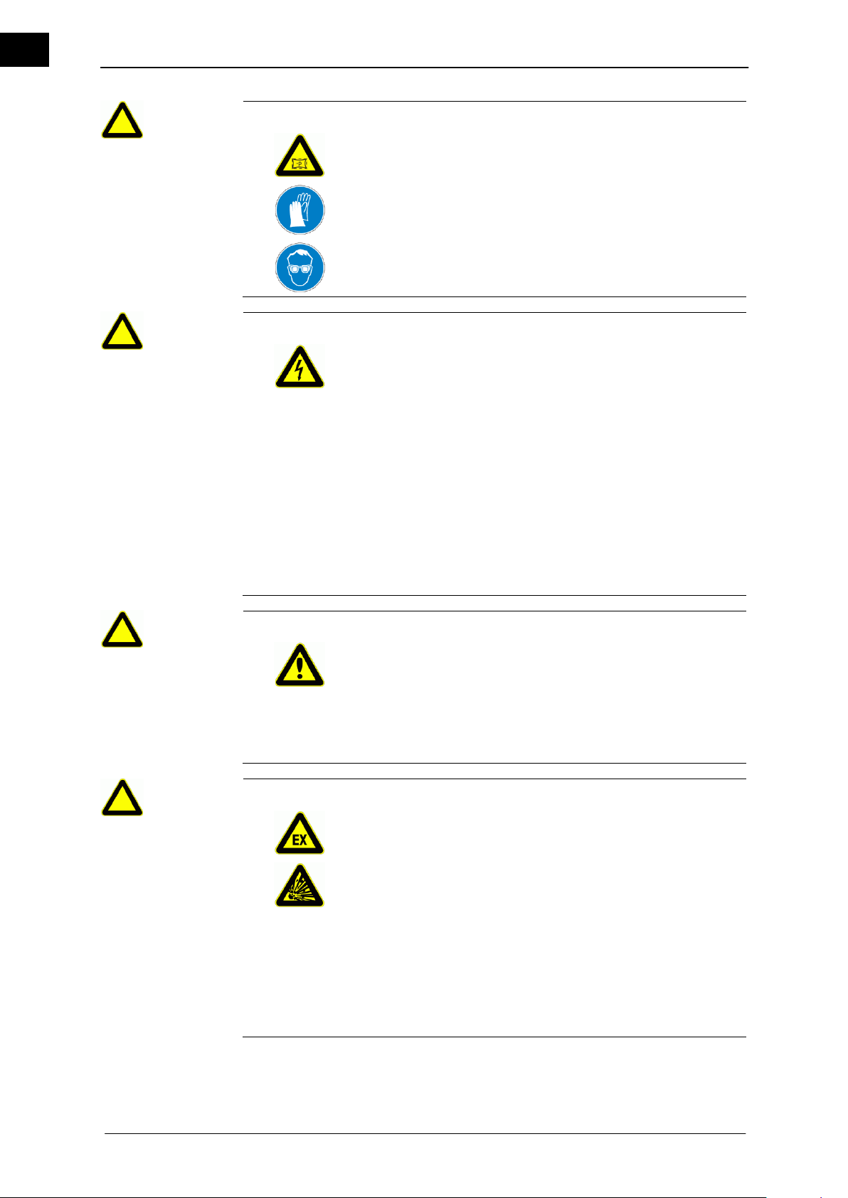
Basic safety instructions
EN
WARNING
Imploding glass devices!
Serious injuries from shattering glass.
Check glass devices for damages (stars, breaks, cracks, etc.)
Only use perfect glass devices and replace all damaged
glassware as soon as possible..
Verify that the interior and exterior pressure variance equals
no more than 2 bar.
DANGER
Potential loss of life due to dangerous electrical voltage!
Serious risk of injuries.
Residual electrical energy remains in the electrical wires, equip-
ment and machines, when the evaporator is switched off.
Inform operating personnel of outlets. Disconnect the sockets
from the power source to completely de-energize.
Work on the power supply must only be performed by an
electrician. Switch off the power switch.
Disconnect the evaporator from the power supply. Routinely
check the electrical equipment (power lines) of the evaporator
for any wear or fraying of wires.
Replace burned or melted power lines. Routinely check all
power cables for damages within the scope of maintenance
and repair services.
Only disconnect the basic device with the heating bath if the device is de-energized. Unplug main power supply.
DANGER
Risks of injuries and mortal danger when disregarding safety
instructions and safe distances!
Risk of injury.
Risks exist when disregarding safety instructions and the safe
distance to the machine.
Observe safety instructions and signs on the evaporator and
in these operating instructions. Adhere to the corresponding
safe distance to the equipment.
DANGER
Danger of fire and explosions!
Serious risk of fire and explosions.
A risk of fire and explosions exists in the vicinity of the evaporator.
Fire, open flame and smoking are prohibited near the equipment.
Flammable liquids may not be stored within the danger zone
of the evaporator. A fire extinguisher must be kept near the
equipment.
Avoid potential ignition sources, such as ignitable atmos-
pheres or reactions or electrostatic charges.
Avoid exothermic reactions or the spontaneous ignition of
dust.
Avoid adiabatic compression and shock waves.
Particular caution to reactions of explosion group IIC, in which
hydrogen can develop.
10 Hei-VAP Value, Hei-VAP Advantage
Page 19
EN
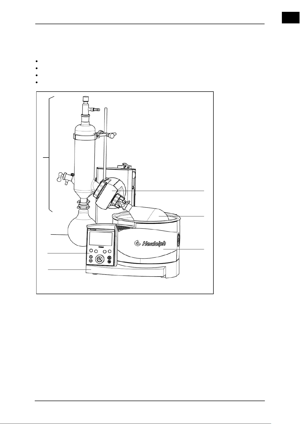
3 Unit Description
1
Drive unit with vapor tube and
coupling clamp
4
Base unit
duct 5 Control panel
2
Evaporator flask
6
Receiving flask
3
Heating bath
7
Condenser
Unit Description
1 2 3 4 5 7
6
Rotary evaporators Hei-VAP Value, Hei-VAP Advantage, Hei-VAP Precision serve the
distillation or evaporation of solvents (chemicals)
purification of chemicals, substances, mixtures and preparations
processing reaction batches
drying of powder
Figure 3–1: Rotary evaporator, here a Hei-VAP Precision with glassware set G3
The solvent to be evaporated is present in the evaporator flask (2). Depending on the
thermodynamic properties of the solvent, the solvent is evaporated by a suitably selected
combination of the heating bath temperature (3) and the vacuum. The settings are made
on the control panel (5) of the base unit (4). The drive unit (1) provides a rotation, which
reduces the risk of boiling evaporation and accelerates the evaporation process by increasing the surface area of the solvent. The solvent vapor reaches the condenser (7)
via the vapor tube, is condensed and then flows into the receiving flask (6).
Hei-VAP Value, Hei-VAP Advantage 11
Page 20

EN
Description
Completion
Quantity
Hand lift truck (HL)
Motor lift (ML)
Glassware set
Standard
coated
Standard
coated
Hei-VAP
Value
G1 diagonal
condenser
1
560-01100-00
560-01110-00
or
Hei-VAP
Value
G3 vertical condenser
1
560-01300-00
560-01310-00
or
Hei-VAP
Value
G5 cold trap
1
560-01500-00
560-01510-00
or
Hei-VAP
Value
G6 return condenser
1
560-01600-00
560-01610-00
or
Hei-VAP
Advantage
G1 diagonal
condenser
1
561-01100-00
561-01110-00
562-01100-00
562-01110-00
or
Hei-VAP
Advantage
G3 vertical condenser
1
561-01300-00
561-01310-00
562-01300-00
562-01310-00
or
Hei-VAP
Advantage
G5 cold trap
1
561-01500-00
561-01510-00
562-01500-00
562-01510-00
or
Hei-VAP
Advantage
G6 return condenser
1
561-01600-00
561-01610-00
562-01600-00
562-01610-00
or
Hei-VAP
Precision
G1 diagonal
condenser
1
563-01100-00
563-01110-00
564-01100-00
564-01110-00
or
Hei-VAP
Precision
G3 vertical condenser
1
563-01300-00
563-01310-00
564-01300-00
564-01310-00
or
Hei-VAP
Precision
G5 cold trap
1
563-01500-00
563-01510-00
564-01500-00
564-01510-00
or
Hei-VAP
Precision
G6 return condenser
1
563-01600-00
563-01610-00
564-01600-00
564-01610-00
Description
Quantity
Order No.
Standard
NS 29 / 32
Order No.
NS 24 / 40
Glassware set G1
1
513-00100-00
513-00140-00
or
Glassware set G3
1
513-00300-00
513-00340-00
or
Glassware set G5
1
513-00500-00
513-00540-00
or
Glassware set G6
1
513-00600-00
513-00640-00
or
Glassware set G1 coated
1
513-00110-00
513-00150-00
or
Glassware set G3 coated
1
513-00310-00
513-00350-00
or
Glassware set G5 coated
1
513-00510-00
513-00550-00
or
Glassware set G6 coated
1
513-00610-00
513-00650-00
4 Set-up and Start-up
4.1 Scope of delivery
12 Hei-VAP Value, Hei-VAP Advantage
Page 21
Set-up and Start-up
EN
Description
Quantity
Order number
Vapor tube coupling clamp with swing
clamp
1
23-09-03-01-03
Tension spring
1
22-03-02-01-05
PTFE 26 vacuum seal
1
23-30-01-01-30
Clamping piece 26
1
23-30-01-05-31
Operating instructions
Hei-VAP Value / Hei-VAP Advantage
1
01-005-004-79
Operating instructions Hei-VAP Precision
1
01-005-004-92
Warranty / declaration of non-objection
1
01-006-002-58
Description
Quantity
Order number
Power cable (EC)
1
14-300-009-81
Power cable for the US
1
14-300-009-82
Power cable for GB
1
14-300-009-83
Power cable for Switzerland
1
14-300-009-84
Description
Quantity
Order No.
Standard
NS 29
Order No.
NS 24
Swing clamp
1
23-30-01-05-29
23-30-01-05-57
Description
Quantity
Order number
Upgrade kit Advantage Precision-HL
1
569-30009-00
Upgrade kit Advantage Precision-ML
1
569-40009-00
Included with the equipment:
Table 4-1: Scope of delivery
Accessories
Table 4-2: Accessories
Unpack the rotary evaporator and check for completeness and any potential shipping damages.
Inform the Service Department of Heidolph Instruments in case of any damages (see chapter 9.4).
Hei-VAP Value, Hei-VAP Advantage 13
Page 22
Set-up and Start-up
EN
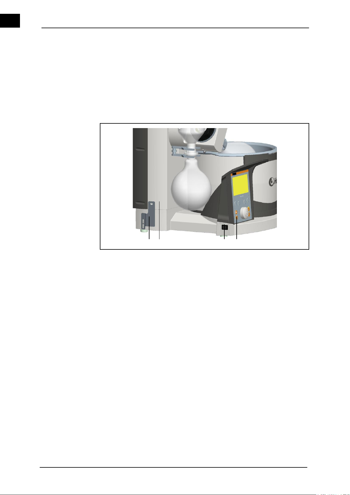
1
Transportation safety device
4
Button – lift down
2
Front shell of lift
5
Button – lift up
3
Power switch
Transportation
safety device
1 2 3
4 & 5
4.2 Transport
The motor lift units have a transportation safety device, which must be removed prior to
the initial start-up of the unit or reattached prior to the return shipment. This is very important in shipping any return or repair of motor lift unit to make sure transport lock is
assembled.
A brief description of the procedure for removing and reattaching the transportation safety device may be found in the following.
The transportation safety device consists of three M5x8 screws and a connecting plate
with holes for fixing the position.
Figure 4–1: Transportation safety device
4.2.1 Removing the transportation safety device
All hose and cable connections to other devices, and the coolant/vacuum connec-
tion are disconnected.
Connect the unit and set the power switch (3) at on.
1. Remove the top screw (in the front shell of the lift (2)) and the lower screw of the
transportation safety device (1) in the switched state. Never tighten in the top position!
2. Remove the screws and the transportation safety device (1) and store.
3. Move the hoist up by using the "lift up" (5) button. Switch the unit off and on.
4.2.2 Attaching the transportation protection device before packing
All hose and cable connections to other devices and the coolant/vacuum connection
are disconnected.
Connecting the unit
1. Continue pressing the lift position contact down when switching the unit on (this will
suppress the "lift to the top when power off" function).
2. Move the hoist down by using the "lift down" (4) button.
Please pay attention to the lift-height stop!
3. Hold the transport safety device as shown in Image 4-1 and fix it with the screws
M5x8 (3 pieces).
14 Hei-VAP Value, Hei-VAP Advantage
Page 23
Set-up and Start-up
EN
CAUTION
Vibrations and shocks!
Damaging the housing and the mechanical system of the equipment.
Avoid vibrations and shocks.
Avoid setting up the rotary evaporator in corrosive atmospheres.
This reduces the service life of the equipment.
CAUTION
Tilting the heating bath!
Damaging the housing and risk of injuries.
Place the basic unit on a solid level surface with sufficient
room.
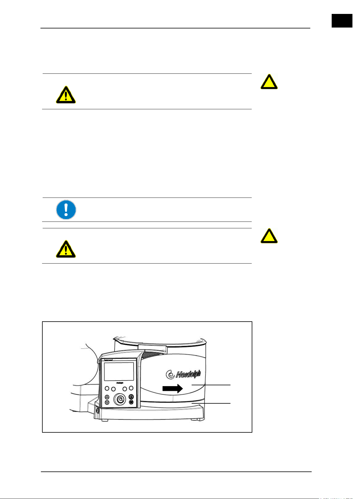
1
Heating bath
2
Base plate
Where?
Start-up
Installing the heating bath
2
1
4. Switch off the unit.
5. Remove the plug.
6. Package the unit.
Carry the basic unit from below.
4.3 Setting up the basic unit
Chemicals may reach the atmosphere (via the pump) when handling hazardous materials and distilling solvents.
Verify that harmful fumes or gases do not affect the operating personnel. The pump
exhaust air must be channeled to an exhaust hood or condensate condenser.
Verify that the interior and exterior pressure variance equals no more than 2 bar.
Verify that the emergency stop for the power supply is always easy to reach.
Select a level, solid, and heat resistant surface.
4.4 Start-up
4.4.1 Installing the heating bath
The basic unit is located on a suitable place.
Figure 4–2: Heating bath
Hei-VAP Value, Hei-VAP Advantage 15
Page 24
Set-up and Start-up
EN
When using de-ionized or distilled water:
Offset water with 0.2 % borax (Na2B4O7 *10 H2O) to prevent
corrosion associated with these purified waters to the stainless steel of the heating bath.
The minimum-/maximum specifications in the heating bath refer
to the liquid level when the evaporator flask is immersed.
Location of the heating bath
The base unit is located on a suitable surface.
Verify that sufficient space (approx. 20 cm around the evaporator) and a solid seating are available in the shifting area.
Verify a solid seating of the heating bath base and the bath.
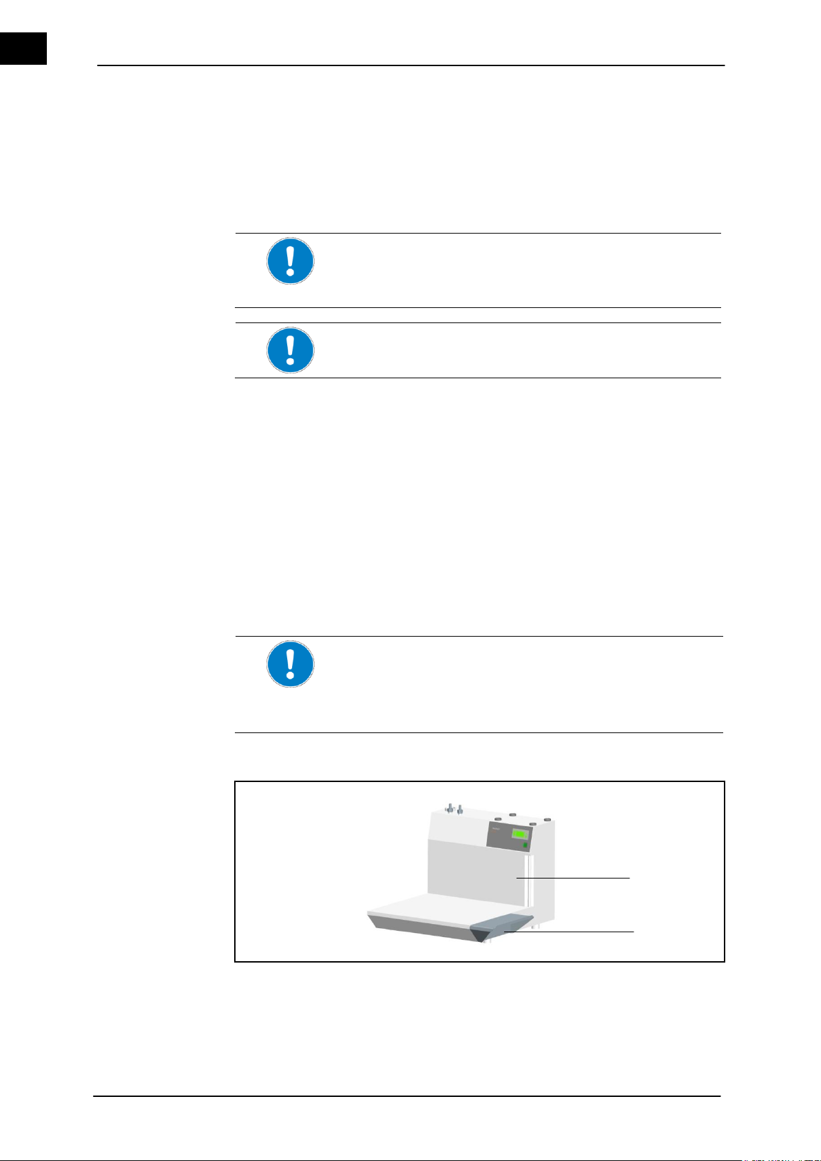
1
Rotacool
2
Rotacool extension plate
Fill the heating bath
Offsetting the heating bath
Heating bath set-up
when using Rotacool
1
2
1. Place the base plate (2) on the surface for the heating bath (1) into the provided rail,
so that the heating bath cannot tilt.
2. Place the heating bath into the rails by its feet. Be careful that the heating bath connection points to the right rear.
4.4.2 Fill the heating bath
The heating bath can be filled with various heat transfer fluids.
1. Select a liquid suitable for your application, such as tap water, water-soluble polyethylene glycol or oil of a lower viscosity (40 cP) and flash point (observe the Safety
Data Sheet)> 260 ° C.
2. Immerse the evaporator flask.
3. Fill the heating bath with the media of choice. The level should be within the minimum and the maximum marking in the heating bath.
4.4.3 Offsetting the heating bath
It will be necessary to expand the distance of the heating bath to the drive unit when
using large evaporator flasks or intermediate pieces between evaporator flasks and the
vapor tube, such as bump flasks or foam brake flasks.
Shift the heating bath including the base plate by the handle on the rail and position
accordingly (Figure 4–2: Heating bath).
4.4.4 Heating bath set-up when using Rotacool
16 Hei-VAP Value, Hei-VAP Advantage
Page 25
Set-up and Start-up
EN
Location of the heating bath when using Rotacool
The base unit is located on a suitable surface.
Verify that sufficient space (approx. 20 cm around the evaporator) and a solid seating are available in the shifting area and
the Rotacool.
Verify a solid seating of the heating bath base and the bath as
well as the Rotacool extension.
CAUTION
Supply voltage and the voltage information on model tag do not
match!
Damage due to incorrect voltage.
Verify that the voltage specified on the model tag corres-
ponds with the mains voltage.
Only disconnect the basic device with the heating bath if the device is de-energized. Unplug main power supply.
CAUTION
The drive unit and the heating bath may be switched on accidentally!
Injuring and burning hands.
Risk of entanglement
Injuries to hands.
Verify that the power switch for the base unit and the heating
bath is switched off by the rocker switch.
Country-specific equipment connection cable
The design of the equipment is equipped with a Euro connector
(EN 50075) for 230/240 V by default, and with a US standard plug
(NEMA Pub. No. WDI. 1961 ASA C 73.1 for a design for 120 V.
1961, page 8, 15 A 125 V).
The main power cable of the device has an integrated protective
ground connection.
Please note if the appropriate equipment connection cable for
your country was included and use it.
Equipment connection cable for:
EU
Great Britain
Switzerland
USA
Connect the base unit
1. Place the two screws on the right side of the extension plate of the Rotacool.
Contact a local Heidolph Distributor if using a previously purchased Rotacool before
July, 2009 for proper attachments of the extension plate.
2. Check the extension plate (2) for proper seating.
4.4.5 Connect the base unit
Hei-VAP Value, Hei-VAP Advantage 17
Page 26
Set-up and Start-up
EN
In order to operate the equipment in a country with a different
connector system, one can use approved adapters only or have a
licensed electrician replace the plug with one suitable and approved for the power supply with protective ground connection.
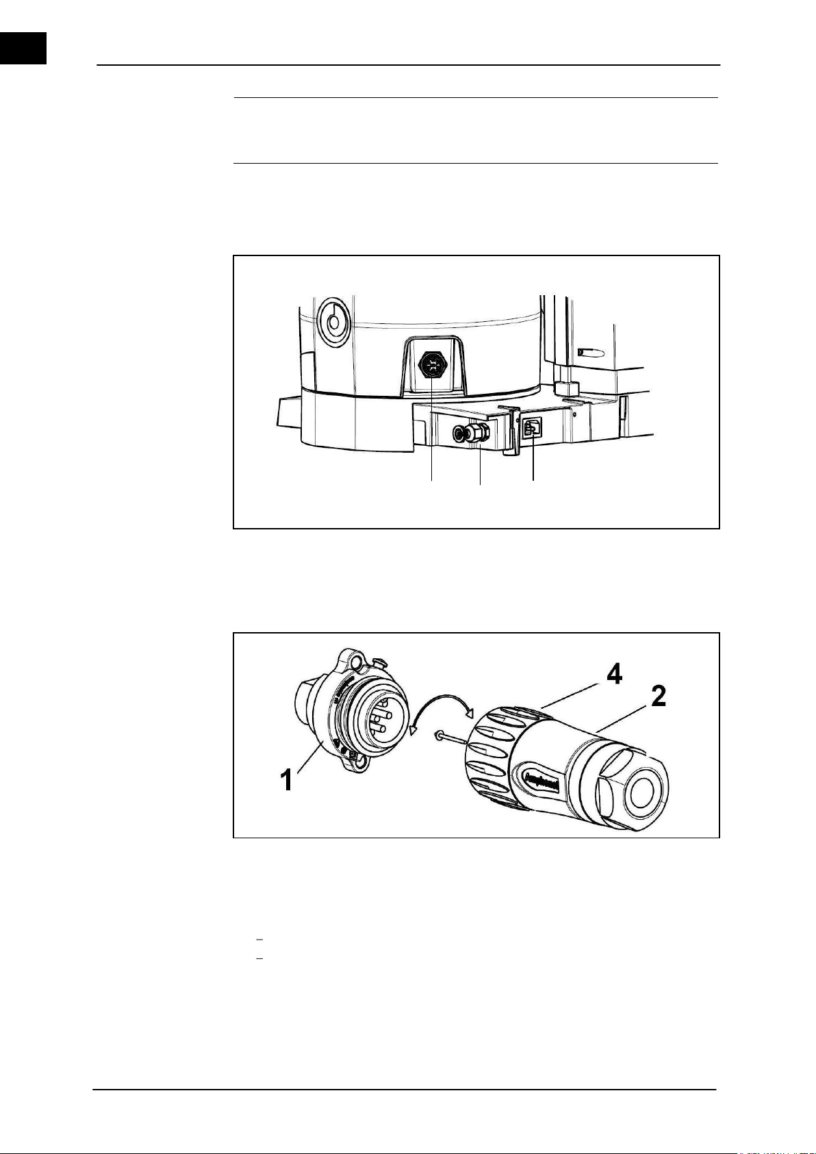
1
Heating bath unit plug
2
Heating bath connecting line (symbolically without a cable and connector)
3
Power supply connector
Connection versions
1 2 3
The plug sockets are located on the back of the unit.
The unit is switched off.
The heating bath is installed on the base console.
Figure 4–3: Connections
Figure 4–4: Heating bath connector
1. Plug the socket of the heating bath connecting cable (2) of the Hei-VAP base into
the appropriate connector (1).
2. Plug the socket (2) with the cap nut (4) of the heating bath connecting cable (7-pin)
into the heating bath:
Press the socket into the connector so that the locking stub fits into the groove.
Grab the socket (2) on the knurled nut (4) and turn the knurled nut clockwise to
fix it.
3. Plug the power supply cable into the power supply plug on the back panel of the
base unit.
4. Connect the power cable to the power supply.
18 Hei-VAP Value, Hei-VAP Advantage
Page 27
Set-up and Start-up
EN
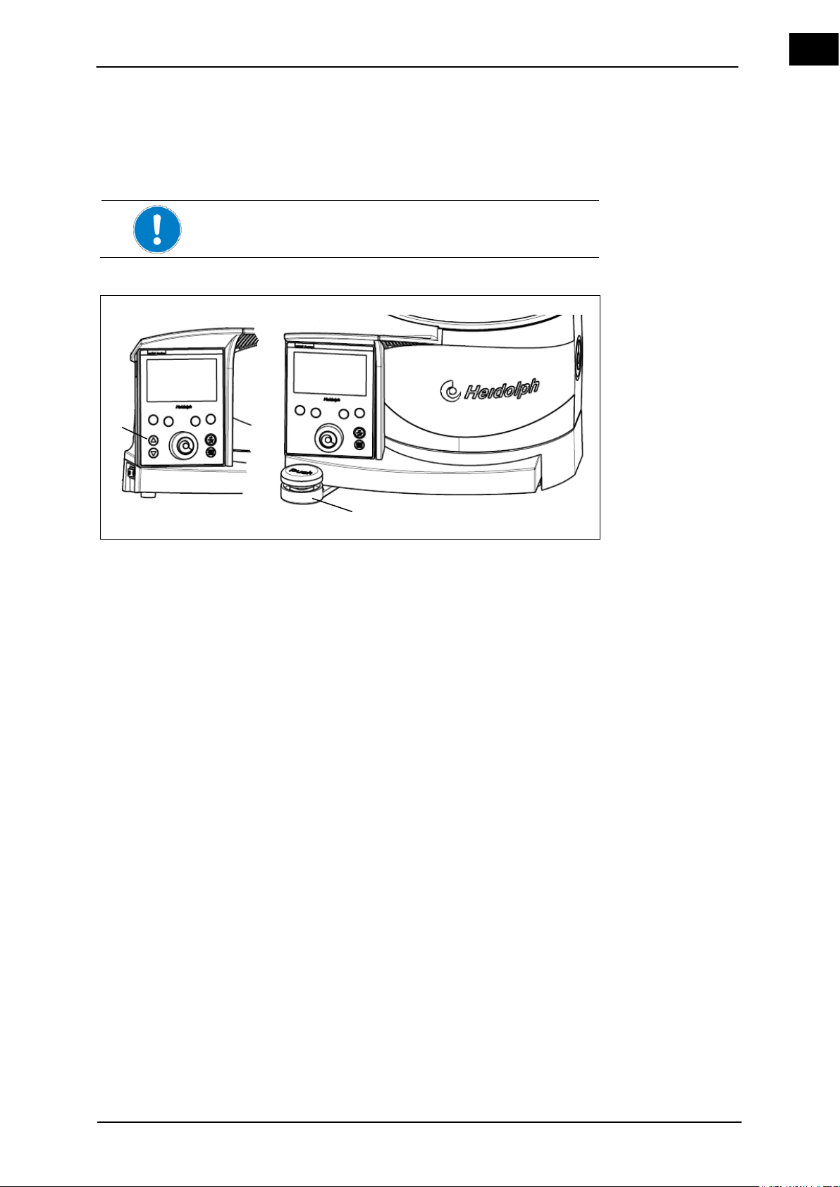
Only immerse the flask so far in the heating bath, so that it does
not contact the edge or the bottom of the bath.
1
Hand lift
2
Motor lift arrow keys
Hand lift
Hand lift
Motor lift
Assemble glassware sets
1
2
4.4.6 Operating the lift
In order to be able to control the immersion depth of the evaporator flask, the height of
the drive unit must be adjusted.
Version Hei-VAP Value, Hei-VAP Advantage, Hei-VAP Precision (hand lift)
Figure 4–5: Hand/motor lift
Hand lift version Hei-VAP Advantage, Hei-VAP Precision
1. Push the hand lift (1) down and shift to the left (lower) or right (upward) while keeping the handle depressed.
2. Release the hand lift (1) at the desired position.
The drive unit snaps into the appropriate position when released.
Motor lift version Hei-VAP Advantage, Hei-VAP Precision
The base unit is installed.
Press the respective arrow key (up/down) (see Figure 4–5 (2) and release the push-
button at the desired position of the drive unit.
The drive unit remains in the proper position set by the operator.
4.5 Assemble glassware sets
Assembling the glassware sets will be described in the following. The rotary evaporators
can be equipped with various glassware sets.
The base unit is set up and installed.
A water or coolant connection is available (does not apply for glassware set G5).
Lift is in the top position (see chapter 4.4.6).
Hei-VAP Value, Hei-VAP Advantage 19
Page 28
Set-up and Start-up
EN
WARNING
Glass breakage!
Serious injuries from shattering and breaking glass.
Check glass devices for damages (stars, breaks, etc.).
Only use perfect glass devices and replace all damaged
glassware as soon as possible.
Work carefully.
CAUTION
Unintentionally rotating drive!
Injuries to hands.
Verify that the rotation is displayed.
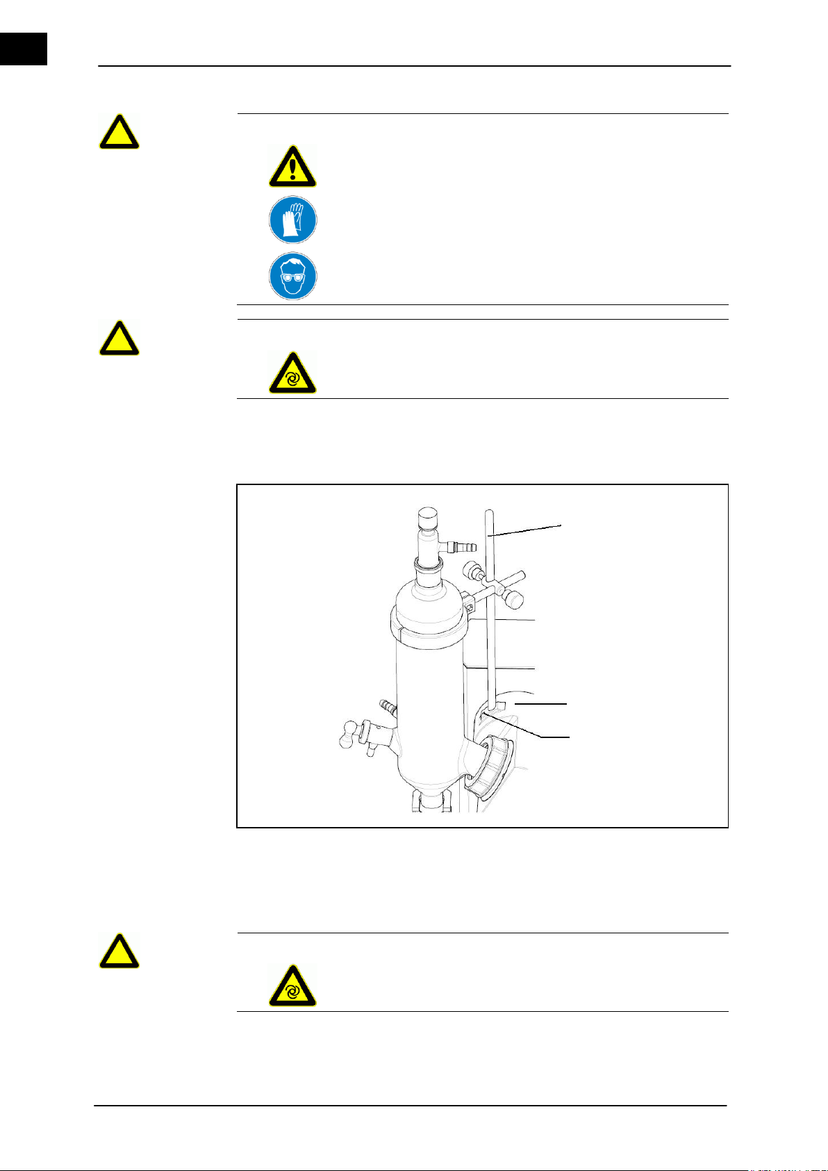
1
Support rod
2
Drive unit
3
Fastening screw - support rod
CAUTION
Unintentionally rotating drive!
Injuries to hands.
Verify that the rotation is displayed.
Install the condenser mounting
3
1
2
4.5.1 Install the condenser mounting (G3-G6)
In order to protect the glassware sets with vertical condensers from accidentally tilting,
they are supported by a condenser mounting and support rod.
Figure 4–6: Install the condenser mounting
20 Hei-VAP Value, Hei-VAP Advantage
Page 29
Set-up and Start-up
EN
WARNING
Risk of injuries due to retracting or entrapment!
Risk of injury.
A risk of entanglement exists on the movable parts of the unit.
Wear suitable protective clothing for activities on the rotary
evaporator with goggles and gloves.
WARNING
Glass breakage!
Serious injuries from shattering and breaking glass.
Check glass devices for damages (stars, breaks, etc.).
Only use perfect glass devices and replace all damaged
glassware as soon as possible.
Work carefully.
CAUTION
Unintentionally rotating drive!
Injuries to hands.
Verify that the rotation is displayed.
WARNING
Risk of injuries due to retracting or entrapment!
Risk of injury.
A risk of entanglement exists on the movable parts of the unit.
Wear suitable protective clothing for activities on the rotary
evaporator with goggles and gloves.
Install the vapor tube
Attach the support rod (1) to the drive unit (2) via a fastening screw (3).
4.5.2 Install the vapor tube
The evaporator flask and the vapor tube are connected with the condenser and the rotation of the evaporator flask is made possible by the drive unit.
Hei-VAP Value, Hei-VAP Advantage 21
Page 30
Set-up and Start-up
EN
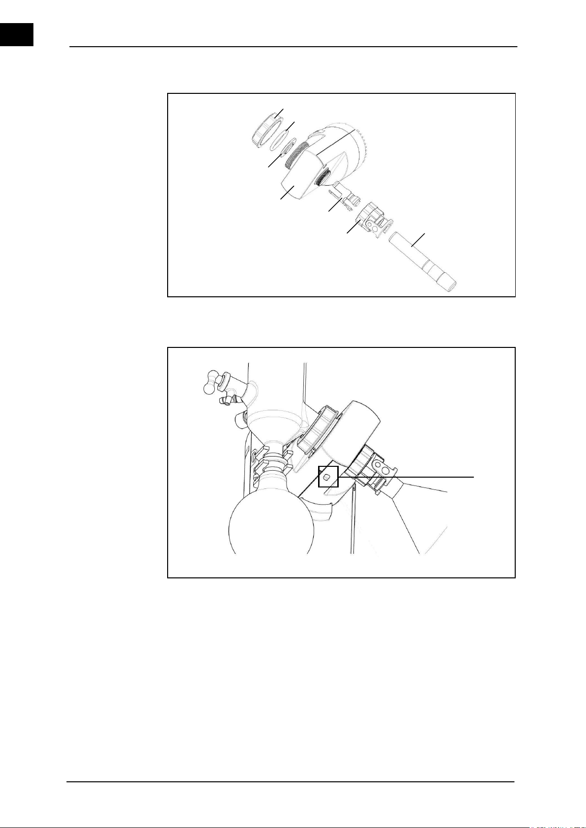
Locking buttons
3 4 5 6 7 1 2
1
1. Remove the vapor tube from the packaging.
Figure 4–7: Install the vapor tube
2. Remove the threaded clamping screw (1) on the drive unit; remove the tension
spring (2) and PTFE 26 vacuum seal (3).
Figure 4–8: Locking button
3. Continue to press the locking button (Figure 4–8 (1)).
4. Remove the screw coupling connection of the vapor tube (Figure 4-7 (6) from the
drive unit.
5. Pull out the clamping sleeve (Figure 4–7 (5).
6. Push the vapor tube coupling clamp (Figure 4–7 (6)) and clamping sleeve (Figure 47 (5)) with the bead first to the vapor tube (Figure 4–7 (7)). Verify that the bead audibly snaps into the groove of the vapor tube (Figure 4–7 (7)).
7. Push the vapor tube (Figure 4–7 (7) into the drive unit with the pre-assembled parts.
8. Continue to press the locking button (Figure 4–8 (1)).
9. Manually tighten the vapor tube coupling clamp (Figure 4–7 (6)) with the threaded
connection of the motor drive (Figure 4–7 (4)) till a tight connection is made.
22 Hei-VAP Value, Hei-VAP Advantage
Page 31
Set-up and Start-up
EN
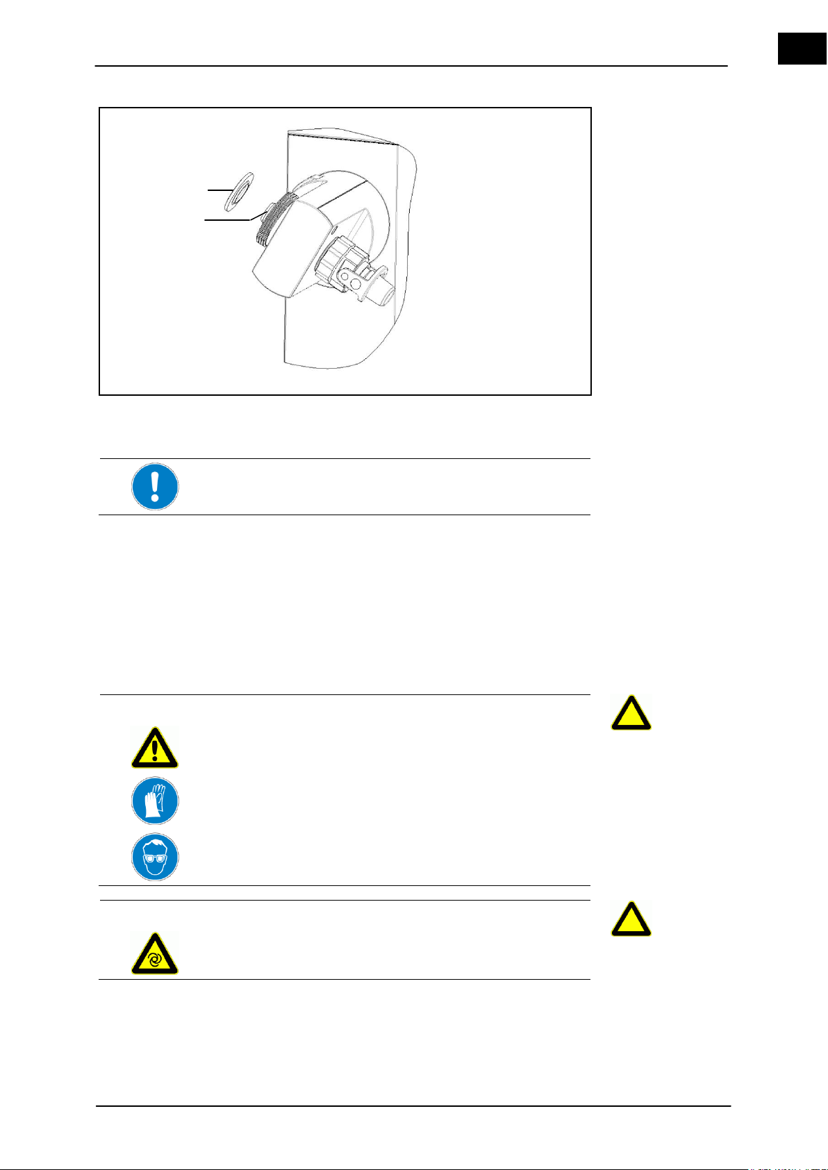
1
PTFE 26 vacuum seal
2
Vapor tube
Do not bend the PTFE 26 vacuum seal or scratch it with pointed
fingernails.
WARNING
Glass breakage!
Serious injuries from shattering and breaking glass.
Check glass devices for damages (stars, breaks, etc.).
Only use perfect glass devices and replace all damaged
glassware as soon as possible.
Work carefully.
CAUTION
Unintentionally rotating drive!
Injuries to hands.
Verify that the rotation is displayed.
PTFE seal on the
vapor tube
Install the condenser
1
2
Figure 4–9: Placing the PTFE 26 vacuum on the vapor tube
10. Push the PTFE 26 vacuum seal (1) onto the vapor tube (2) with the sealing lip in
front (labeling on the drive side in the direction of the drive unit).
4.5.3 Install the condenser
The threaded clamping screw is removed from the drive head.
Spring is removed from the drive head.
The vapor tube is installed on the drive.
PTFE 26 vacuum seal is installed on the vapor tube.
Hei-VAP Value, Hei-VAP Advantage 23
Page 32
Set-up and Start-up
EN
WARNING
Risk of injuries due to retracting or entrapment!
Risk of injury.
A risk of entanglement exists on the movable parts of the unit.
Wear suitable protective clothing for activities on the rotary
evaporator with goggles and gloves.
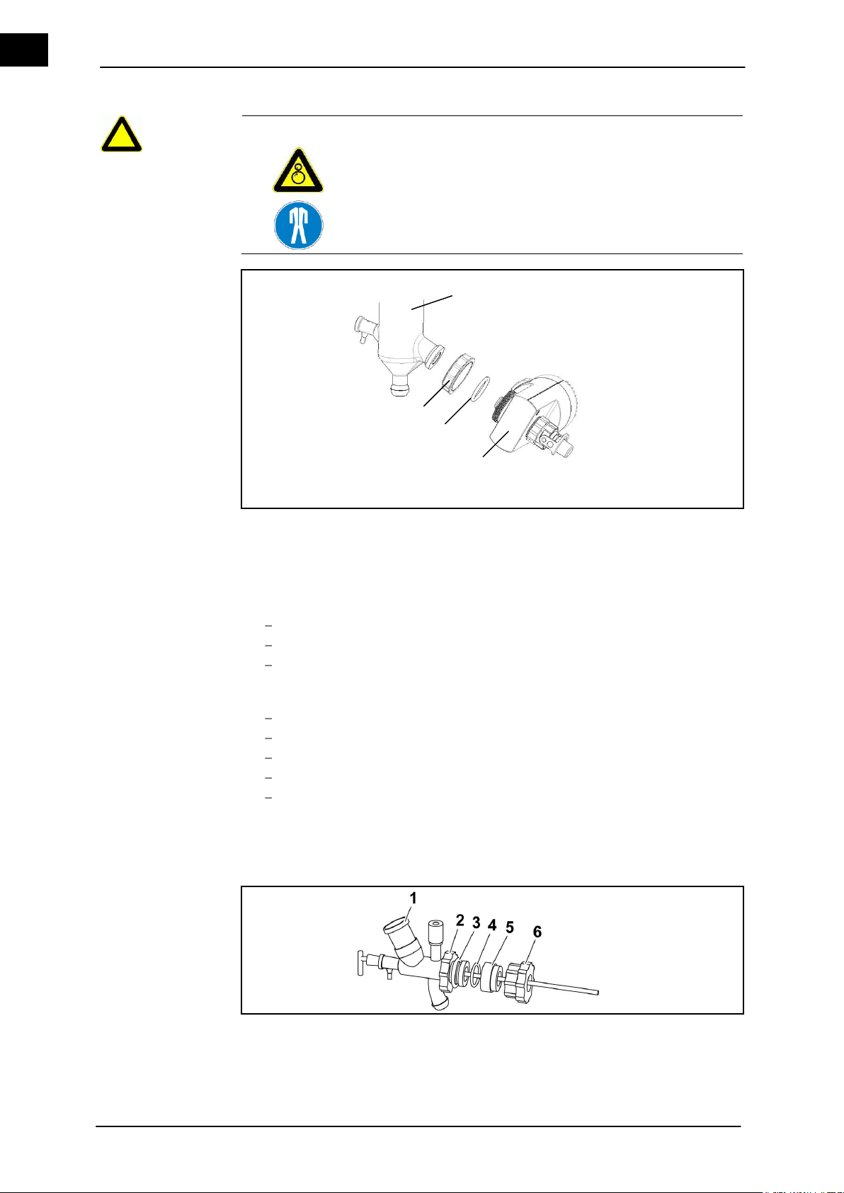
1
Condenser
3
Tension spring
2
Threaded clamping screw
4
Drive unit
1
Center piece
4
Gasket G6
2
Threaded connection
5
G6 intermediate part (5)
3
Tension spring
6
G6 threaded coupling
1 3 2
4
Figure 4–10: Assemble the glassware set (the example here is glassware set G1)
1. Version glassware sets G1 and G3:
Push the threaded clamping screw (2) over the condenser flange.
Push the spring (3) over the condenser flange.
Attach the condenser (1) to the drive unit (4) with the clamping screw.
2. Version glassware set G5 (depending on coolant):
Push the threaded clamping screw (2) over the cold trap jacket flange.
Push the spring (3) over the cold trap jacket flange.
Screw the cold trap jacket with the threaded clamping screw to the drive unit.
Insert the o-ring in the sealing groove of the cold trap jacket.
Insert the PTFE centering ring in the cold trap jacket and insert the cold trap in-
sert (cold finger).
The flange is suctioned compressed by the vacuum and the system is closed vacuumtight by the inserted o-ring.
3. Version glassware set G6 (condenser for return flow distillation):
Figure 4–11: Glassware set G6
24 Hei-VAP Value, Hei-VAP Advantage
Page 33
Set-up and Start-up
EN
1
Support rod
3
Boss head clamp
2
Condenser clamp
Condenser mounting
1 2 3
Push the threaded connection (2) over the condenser flange.
Push the spring (3) over the condenser flange.
Screw the G6 (6) gland on the drive head (Figure 4–10 (4)).
Insert the G6 intermediate part (5) with seal G6 (4) into the gland G6 (6).
Screw the center piece (1) with the screw (2) on gland G6 (6).
Insert the condenser in the upper cut on the center piece (1).
4.5.4 Mount the vertical condenser (G3-G6) in the condenser bracket
This step is omitted for horizontal condensers (G1).
The support rod is installed.
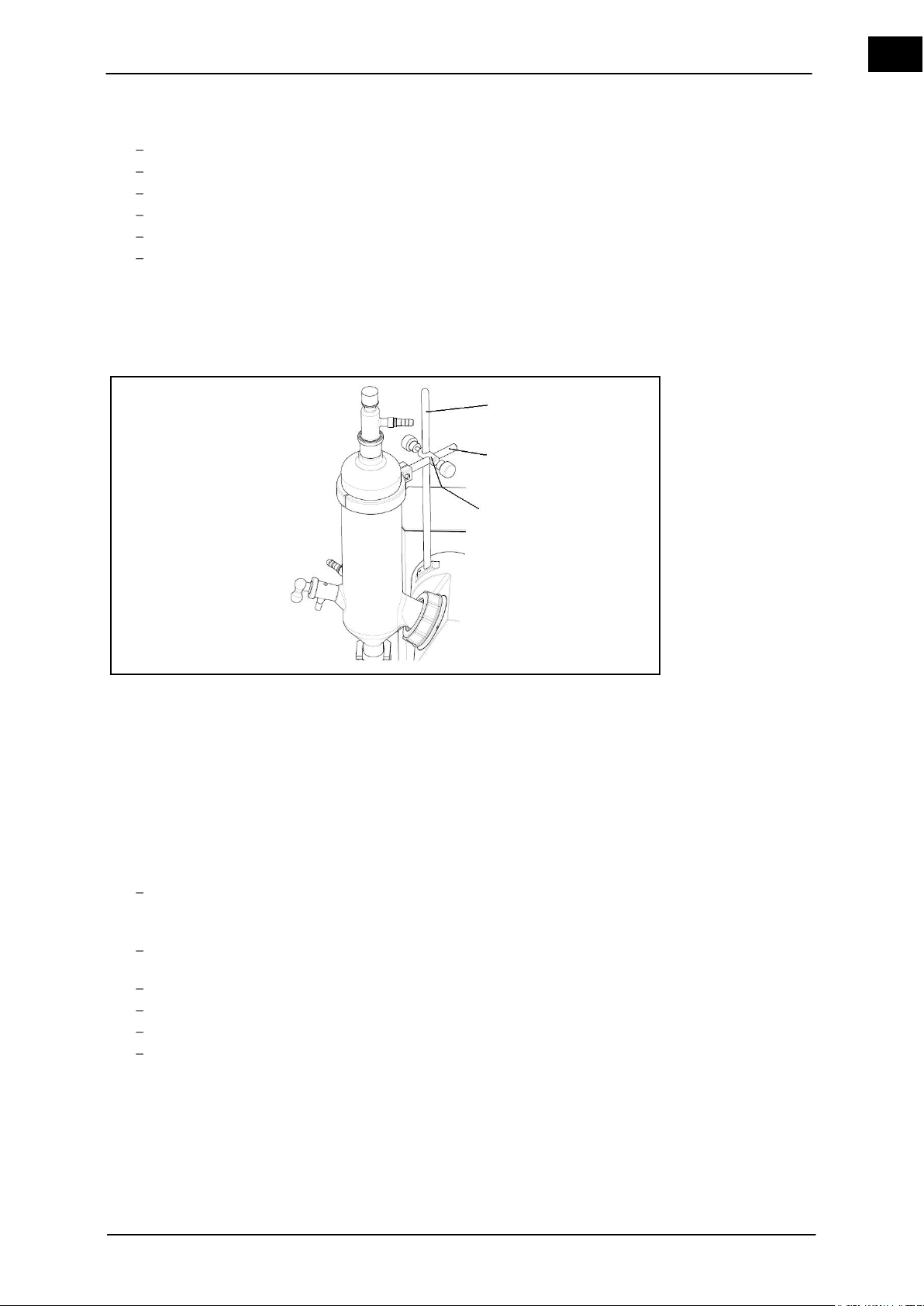
Figure 4–12: Condenser bracket (Glassware set G3 and G6)
Version glassware set G3 and G6:
1. Push the boss head clamp (3) onto the support rod (1) and position with the clamping screw.
2. Place the condenser clamp (2) around the condenser and attach on the support rod
by using the clamping screw.
Position the support rod with Allen screws (also refer to chapter 4.5.1).
Version glassware set G5 (depending on coolant):
Completely place the cold trap bracket into the lateral hole of the boss head
clamp (2).
Lock with the clamping screw.
Place the cold trap bracket on the cold trap jacket.
Position the cold trap jacket with the tension band on the cold trap bracket.
Position the support rod (1) with an Allen screw (also refer to chapter 4.5.1).
Hei-VAP Value, Hei-VAP Advantage 25
Page 34
Set-up and Start-up
EN
WARNING
Glass breakage!
Serious injuries from shattering and breaking glass.
Check glass devices for damages (stars, breaks, etc.).
Only use perfect glass devices and replace all damaged
glassware as soon as possible.
Work carefully.
CAUTION
Unintentionally rotating drive!
Injuries to hands.
Verify that the rotation is displayed.
WARNING
Risk of injuries due to retracting or entrapment!
Risk of injury.
A risk of entanglement exists on the movable parts of the unit.
Wear suitable protective clothing for activities on the rotary
evaporator with goggles and gloves.
1
Jacknut
2
Swing clamp
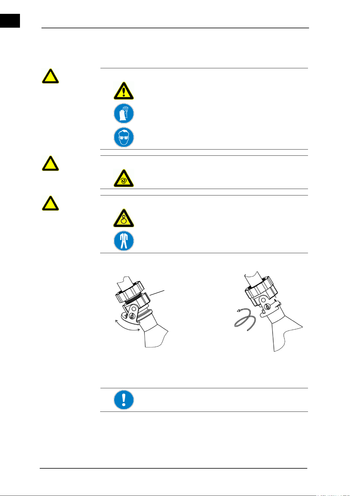
The correct seating of the swing clamp on the flange of the evaporator flask must be observed!
Install the evaporator flask
1
2
4.5.5 Install the evaporator flask
Install the evaporator flask with a permanent flask clamp on the vapor tube.
Figure 4–13: Flask clamp (swing clamp)
26 Hei-VAP Value, Hei-VAP Advantage
Page 35

Set-up and Start-up
EN
CAUTION
Unintentionally rotating drive!
Injuries to hands.
Verify that the rotation is displayed.
WARNING
Risk of injuries due to retracting or entrapment!
Risk of injury.
A risk of entanglement exists on the movable parts of the unit.
Wear suitable protective clothing for activities on the rotary
evaporator with goggles and gloves.
WARNING
Glass breakage!
Serious injuries from shattering and breaking glass.
Check glass devices for damages (stars, breaks, etc.).
Only use perfect glass devices and replace all damaged
glassware as soon as possible.
Work carefully.
Setting the evaporator flask inclination
Evaporator flask
inclination and
immersion depth
1
4.5.6 Setting the evaporator flask inclination
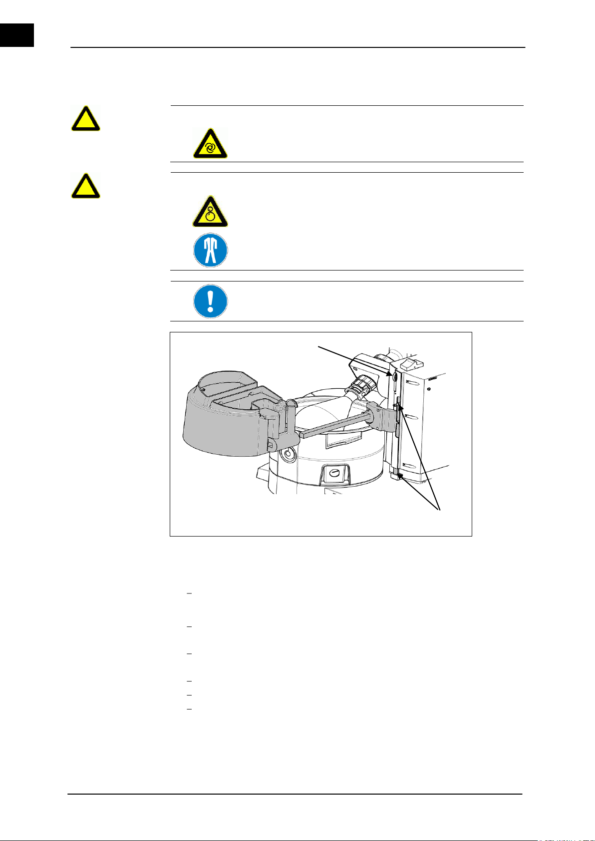
The inclination of the evaporator flask can be set by turning the drive unit.
Figure 4–14: Evaporator flask inclination / immersion depth
1. Grasp the condenser with the left hand.
2. Unlock the locking device (1) at the lift column toward the right by applying pressure
with your right hand.
3. Set the evaporator flask inclination by carefully swinging the condenser.
4. Position the locking device by releasing and snapping it in.
Hei-VAP Value, Hei-VAP Advantage 27
Page 36
Set-up and Start-up
EN
CAUTION
Unintentionally rotating drive!
Injuries to hands.
Verify that the rotation is displayed.
WARNING
Risk of injuries due to retracting or entrapment!
Risk of injury.
A risk of entanglement exists on the movable parts of the unit.
Wear suitable protective clothing for activities on the rotary
evaporator with goggles and gloves.
In order to always guarantee the same immersion depth of the
evaporator flask, we recommend locking the immersion depth.
1
2
4.5.7 Setting the immersion depth of the evaporator flask
Height stop (1) in the top position.
1. Version without a protective cover:
Open the locking lever of the height stop (2) on the right of the lift column.
Manually push the height stop (1) down.
Move the lift down until the desired immersion depth is reached.
2. Close the locking lever on the right of the lift column.
The immersion depth of the evaporator flask is locked.
3. Version with a protective cover:
Move the lift down until the desired immersion depth is reached.
Hold the protective cover with your hand.
Open the locking lever on the right of the lift column.
4. Feed the protective cover with your hand.
5. Close the locking lever on the right of the lift column.
28 Hei-VAP Value, Hei-VAP Advantage
The immersion depth of the evaporator flask is locked.
Page 37
Set-up and Start-up
EN
WARNING
Glass breakage!
Serious injuries from shattering and breaking glass.
Check glass devices for damages (stars, breaks, etc.).
Only use perfect glass devices and replace all damaged
glassware as soon as possible.
Work carefully.
CAUTION
Unintentionally rotating drive!
Injuries to hands.
Verify that the rotation is displayed.
WARNING
Risk of injuries due to retracting or entrapment!
Risk of injury.
A risk of entanglement exists on the movable parts of the unit.
Wear suitable protective clothing for activities on the rotary
evaporator with goggles and gloves.
WARNING
Hot media!
Burns.
Do not touch the interior and the upper edge of the heating
bath, the evaporator flask and the heating bath liquid.
Wear suitable heat protection gloves when changing the
evaporator flask.
WARNING
Glass breakage!
Serious injuries from shattering and breaking glass.
Check glass devices for damages (stars, breaks, etc.).
Work carefully.
4.5.8 Release the evaporator flask from the vapor tube
1. Switch off the rotation.
2. Move the evaporator flask up from the bath (see chapter 4.4.6).
3. Let the evaporator flask cool (Figure 4-13 (1)).
4. Release the vapor tube coupling clamp flask ejector nut.
5. Release the flask from the vapor tube (Figure 4–6 (7)) by turning the vapor tube
coupling clamp flask ejector nut counter-clockwise by supporting the flask.
6. Hold the evaporator flask and release the flask clamp.
7. Carefully remove the flask.
Hei-VAP Value, Hei-VAP Advantage 29
Page 38
Set-up and Start-up
EN
1
PTFE tube
2
Drain-off plate
3
Stopcock
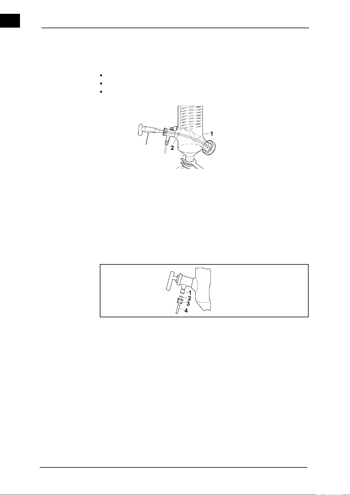
1
Inlet valve connection
3
Cap 2 Seal
4
Inlet tube
Insert the inlet tube
Assemble the inlet tube
3
4.5.9 Insert the inlet tube
The inlet tube consists of:
Stopcock (Stopper)
PTFE tube
Drain-off plate
Figure 4–15: Insert the inlet tube
1. Shorten the PTFE tube (1) to the desired length.
2. Grease the stopcock (3) (optional) for ideal vacuum.
3. Position the drain-off plate (2) so that the condensed liquid cannot return to the
evaporator flask via the PTFE tube (1).
4. Insert the inlet tube
4.5.10 Assemble the inlet tube
Figure4–16: Assemble the inlet tube
1. Guide the inlet tube (4) through the cap (3) and seal (2) assembled on the inlet valve
connection (1).
2. Turn the cap (3) to the right on the inlet valve connection (1).
The inlet tube (4) is assembled on the inlet valve connection (1).
30 Hei-VAP Value, Hei-VAP Advantage
Page 39
Set-up and Start-up
EN
1
Tube (coolant inlet)
3
Return (GL hose barb)
2
Connectors (GL hose barb)
Connect the cooling medium
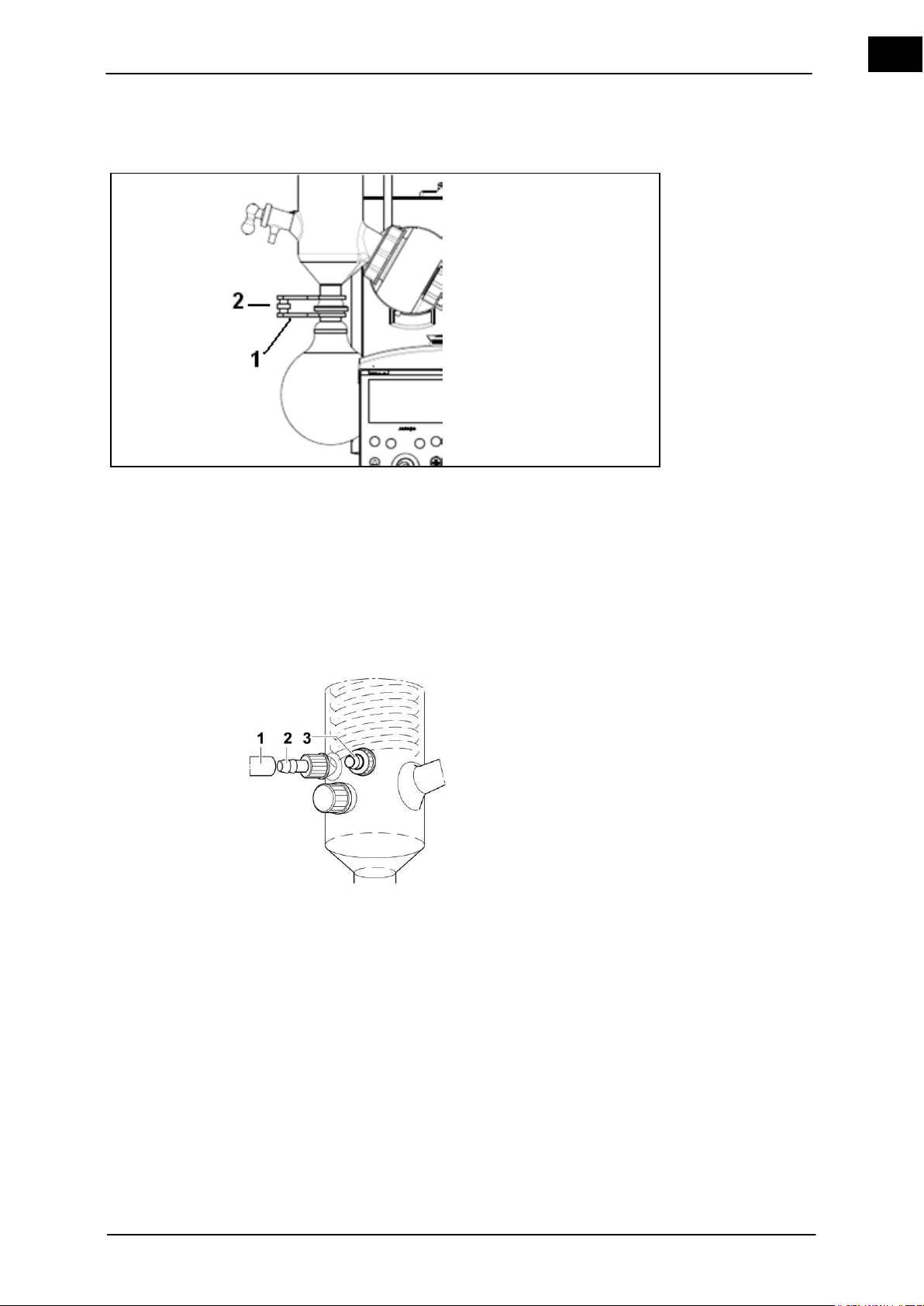
4.5.11 Assemble the collecting flask
1. Hold the receiving flask with the ball-socket clamp KS 35 (1) to the condenser.
2. Secure with a knurled head screw (2).
The socket joint of the receiving flask is attached to the ball joint of the condenser via
pinch clamp KS 35.
4.5.12 Connect the cooling medium (except G5)
Use a suitable tube with an inner diameter of 7-8 mm (i.e. hose set (see accessories
11.2))
Figure 4–17: Connect the coolant
1. Push the tube (coolant supply) (1) onto the hose barb of the inlet connector. Proceed accordingly with the return hose barb (3) of the coolant.
2. Secure with hose clamps.
Feed and return of the coolant are connected by screwing caps onto glass threads.
Hei-VAP Value, Hei-VAP Advantage 31
Page 40
Set-up and Start-up
EN
WARNING
Imploding glass devices!
Serious injuries from shattering glass.
Check glass devices for damages (stars, breaks, etc.).
Only use perfect glass devices and replace all damaged
glassware as soon as possible.
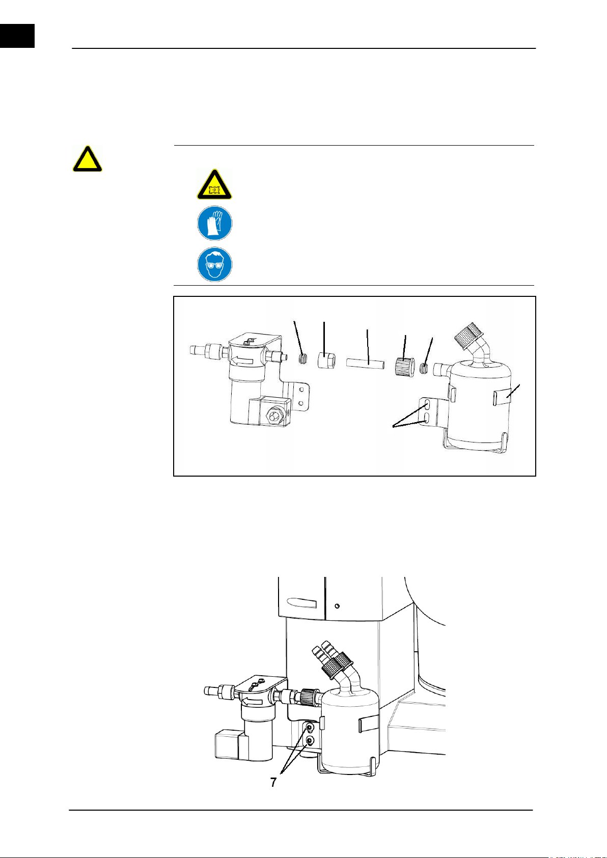
1
Ferrule for the vacuum valve
5
Ferrule for the bottle
2
Cap nut
6
Mounting brackets
3
PTFE tube section
7
Screws
4
Threaded fitting cap
Woulff flask with
vacuum valve
1 3 2 4 5 7 6
4.5.13 Connect the vacuum
The Woulff flask is connected to the vacuum valve (except in the Hei-VAP Precision with
Rotavac vario control or with Rotavac vario tec).
Figure 4–18: Connect the Woulff flask with vacuum valve
32 Hei-VAP Value, Hei-VAP Advantage
Page 41
Set-up and Start-up
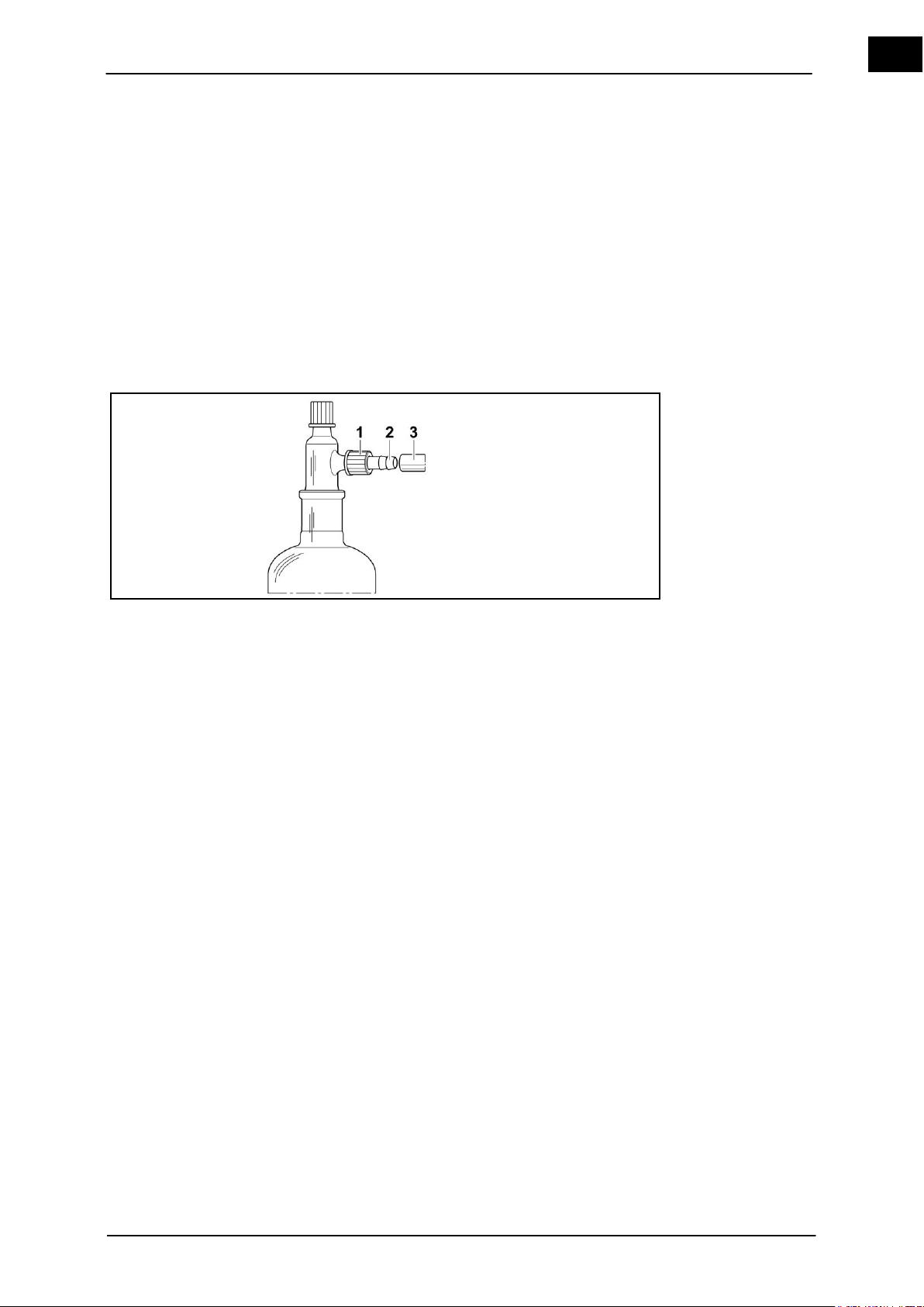
EN
1
Threaded fitting cap
3
Vacuum tube
2
Connector (GL hose barb)
Connection
Vacuum to the
glassware set
Vacuum connection
1. Unscrew the threaded fitting (4) from the Woulff bottle, remove the hose clamp ring
(5).
2. Place the enclosed PTFE tube section (3) in the cap nut (2) and tighten the cap nut
(2).
3. Push the threaded connection (4) on the PTFE tube section (3), also push on the
ferrule compression fitting (5).
4. Connect the Woulff bottle with the ferrule compression fitting (1).
5. The vacuum valve and Woulff bottle are connected.
6. Attach the connected Woulff bottle and the vacuum valve with the mounting brackets (6) and two screws (7) to the base unit.
Suitable vacuum source is available.
Suitable vacuum tube (7-8 mm) is available.
Figure 4–19: Vacuum connection
1. Connect the vacuum hose (3) to the hose barb connector (2) to the threaded fitting
cap (1).
Hose connection of individual vacuum systems, refer to the following pages.
Hei-VAP Value, Hei-VAP Advantage 33
Page 42
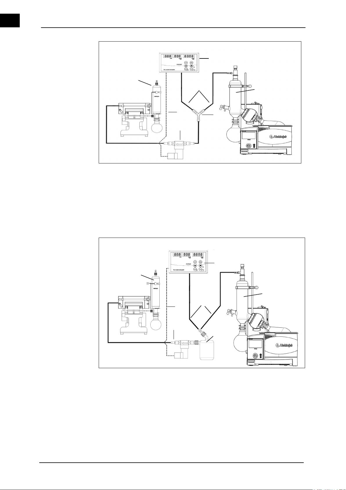
Set-up and Start-up
EN
1
Condenser
8
2
Y-piece
9
Vacuum tube
3
Vacuum valve
10
Vac control automatic
4
Condensate cooler (optional)
11 5
Vacuum valve cable
12
6 13
7
1
Condenser
8 2
Woulff bottle
9
Vacuum tube
3
Vacuum valve
10
Vac control automatic
4
Condensate cooler (optional)
11 5
Vacuum valve cable
12 6 13 7
4
2
3
10
9
Rotavac
* valve control
* valve tec
Vac control automatic
1 5 4 2 3
9
Rotavac
* valve control
* valve tec
Vac control automatic
1
5
10
Figure 4–20: Hei-VAP Advantage with Rotavac valve control and Vac control automatic
34 Hei-VAP Value, Hei-VAP Advantage
Figure 4–21: Hei-VAP Advantage with Rotavac valve control and Vac control automatic
and with Woulff bottle
Page 43
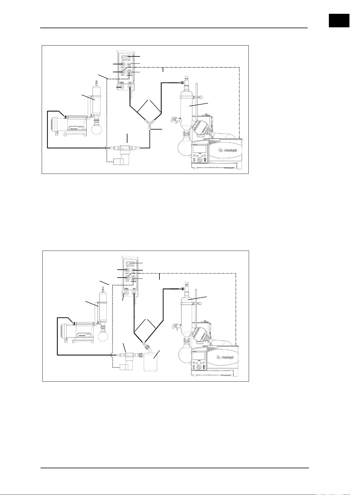
Set-up and Start-up
EN
1
Condenser
8
Ventilation / inert gas
2
Y-piece
9
Vacuum tube
3
Vacuum valve
10
Vacuum valve cable connection
4
Condensate cooler (optional)
11
USB PC connection
5
Vacuum valve cable
12
Bluetooth module
6
Switch box connection
13
Data cable
7
Hei-VAP connection
1
Condenser
8
Ventilation / inert gas
2
Woulff bottle
9
Vacuum tube
3
Vacuum valve
10
Vacuum valve cable connection
4
Condensate cooler (optional)
11
USB PC connection
5
Vacuum valve cable
12
Bluetooth module
6
Switch box connection
13
Data cable
7
Hei-VAP connection
4 2 3 6 7
8
11
12
9
Rotavac
* valve control
* valve tec
13
Vacuum box
1
10
5 4 2 3 6 7 8
11
12
9
Rotavac
* valve control
* valve tec
13
Vacuum box
1
10
5
Figure 4–22: Hei-VAP Precision with Rotavac valve control and vacuum box
Figure 4–23: Hei-VAP Precision with Rotavac valve control and vacuum box and with
Woulff bottle
Hei-VAP Value, Hei-VAP Advantage 35
Page 44
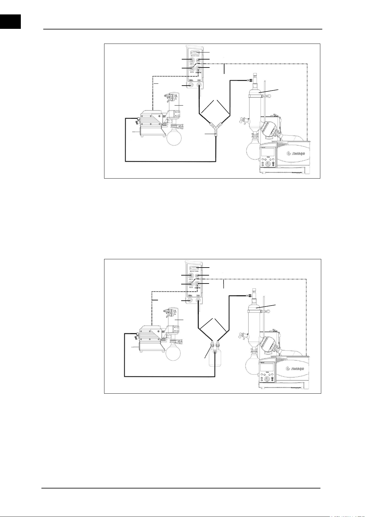
Set-up and Start-up
EN
1
Condenser
7
Hei-VAP connection
2
Y-piece
8
Ventilation / inert gas
4
Emission condensate cooler
(optional)
9
Vacuum tube
5
Control cable
Rotavac vario control /
Rotavac vario tec
10
11
12
Vacuum pump connection
USB PC connection
Bluetooth module
6
Switch box connection
13
Data cable
1
Condenser
7
Hei-VAP connection
2
Woulff bottle
8
Ventilation / inert gas
4
Emission condensate cooler
(optional)
9
Vacuum tube
5
Control cable
10
Vacuum pump connection
Rotavac vario control /
Rotavac vario tec
11
12
USB PC connection
Bluetooth module
6
Switch box connection
13
Data cable
2 5 4
1
13
5 4 9 1 13
Rotavac
* vario control
* vario tec
Rotavac
* vario control
* vario tec
2
6
11
12
6
8
11
12 9 7
8
7
Vacuum box
Vacuum box
10
10
Figure 4–24: Hei-VAP Precision with Rotavac vario tec and vacuum box
36 Hei-VAP Value, Hei-VAP Advantage
Figure 4–25: Hei-VAP Precision with Rotavac vario tec and vacuum box with Woulff
bottle
Page 45

Set-up and Start-up
EN
1
Inlet tube
2
Stopcock
Inlet tube
4.6 Feed the distilled material
Additional distillation material can be supplied during the distillation under vacuum via
the inlet tube and the inlet pipe.
Figure 4–26: Inlet tube
1. Place the inlet tube (1) in the additional distillation material.
2. Turn the stopcock (2) parallel to the inlet tube (1).
The additional distillation material is suctioned into the evaporation flask while system is
under vacuum.
4.7 Ventilate manually
The system can be ventilated with the valve stopcock (Figure 4–26 (2) of the inlet pipe.
Slowly turn the stopcock (Figure 4–26 (2)) of the inlet tube upward.
The system will be ventilated.
Hei-VAP Value, Hei-VAP Advantage 37
Page 46
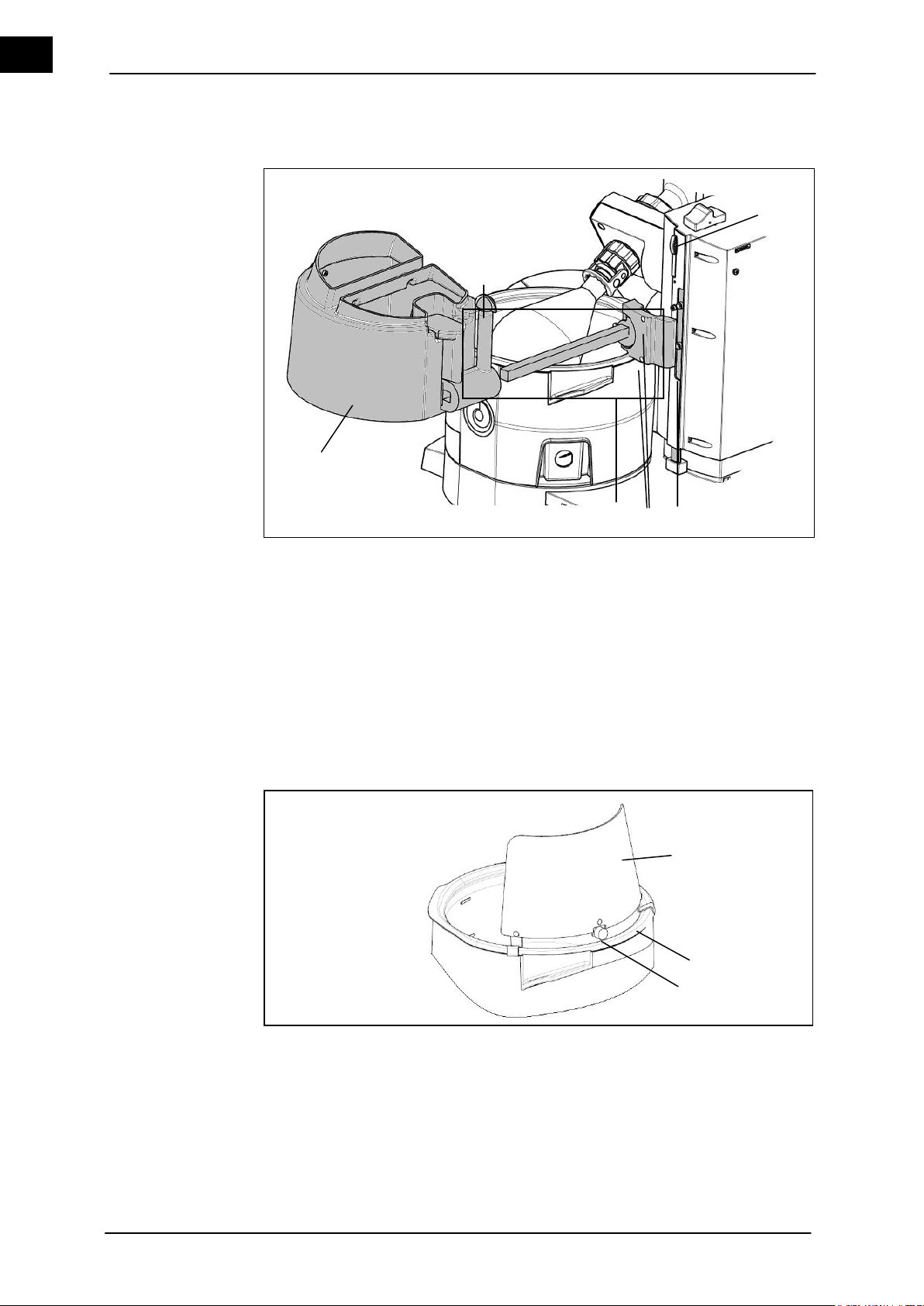
Set-up and Start-up
EN
1
Height stop
4
Lock screw
2
Allen screws
5
Protective hood
3
Support cover
6
Height stop lock
1
Protective shield
3
Eccentric screw
2
Heating bath
Protective hood
Protective shield
1
2
3
5 4 3 2 1
6
4.8 Assemble / connect accessories
Figure 4–27: Assemble the protective cover
1. Screw the support cover (3) to the height stop (1) by using the two enclosed Allen
screws (2).
2. Release the clamping screw (4) and align the cover (5) over the heating bath by
shifting horizontally.
3. Tighten the clamping screw.
The cover is assembled. The cover can be opened by the handle.
Figure4–28: Assemble the protective shield
1. Move the lift upward.
2. Attach the protective shield (1) on the edge of the heating bath (2) and position so
that the (possibly available) cover can be easily opened.
3. Turn the eccentric screw (3) by 180° and use it to attach the protective shield on the
heating bath.
38 Hei-VAP Value, Hei-VAP Advantage
Page 47
Set-up and Start-up
EN
When using the cover and the protective shield, take care that the
two parts do not jam.
1
Plug
2
Seal
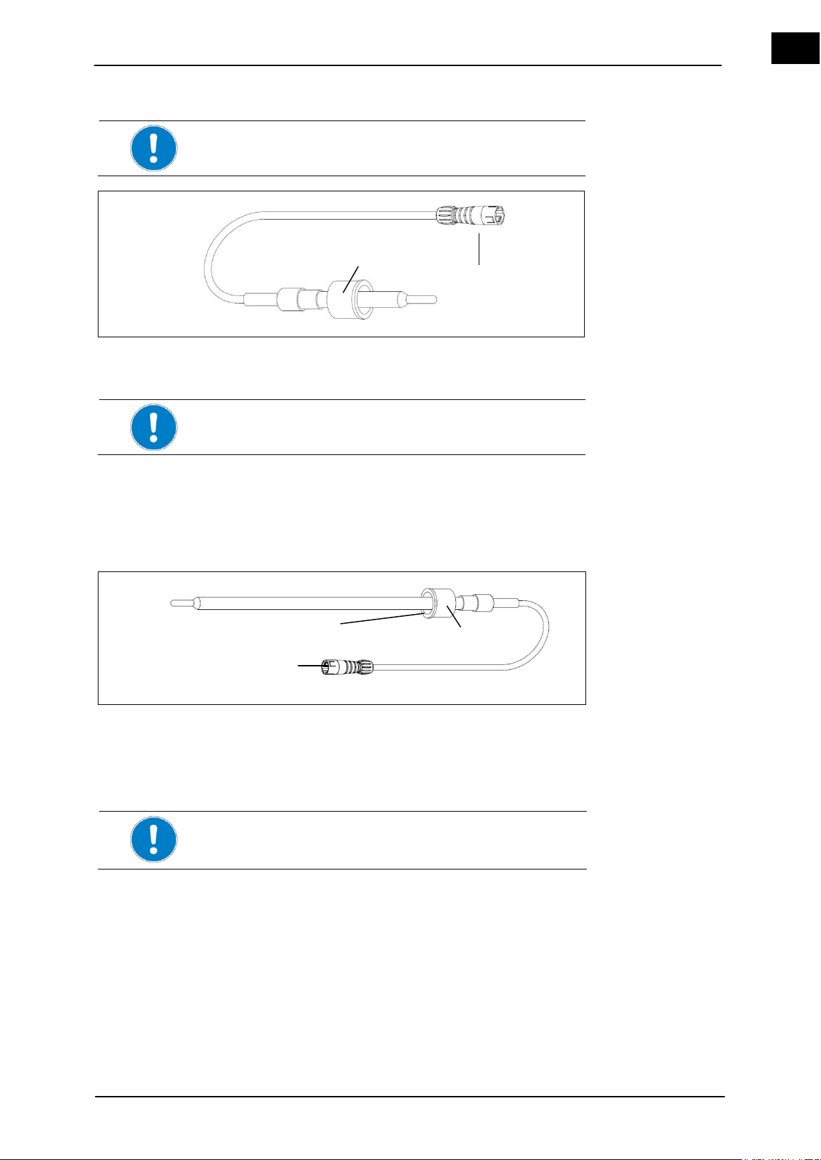
The vapor temperature sensor cannot be used when using the
temperature sensor Auto
accurate
sensor.
1
Threaded fitting cap
3
PTFE side of the sealing tube
2
Plug
Set the depth at which the temperature sensor Auto
accurate
sensor
projects into the condenser so that the lower edge of the sensor is
located at 2/3 of the condenser's height.
Vapor temperature
sensor ( Hei-VAP
Advantage, HeiVAP Precision)
Temperature sensor
Auto
accurate
sensor
1 2 3 1 2
Figure 4–29: Vapor temperature sensor
1. Unscrew the threaded fitting on the condenser.
2. Insert the vapor temperature sensor into the condenser so that the white PTFE side
of the seal (2) points to the glass thread.
3. Screw the vapor temperature sensor together with the threaded fitting.
4. Connect the plug (1) in the socket on the tower to the left of the unit (see chapter 5).
Figure4–30: Temperature sensor Auto
accurate
sensor
Only in conjunction with glassware sets G3 and G6.
1. Unscrew the threaded fitting on the vacuum port.
2. Insert the Auto
sensor into the vacuum port so that the white PTFE side (3) of
accurate
the seal points to the glass thread.
3. The depth of the Auto
Auto
accurate
sensor.
4. Screw together the Auto
sensor is set on the condenser by adjusting the
accurate
sensor with the threaded fitting (1).
accurate
5. Connect the plug (2) in the socket on the tower to the left of the unit (see chapter 5).
Hei-VAP Value, Hei-VAP Advantage 39
Page 48
Set-up and Start-up
EN
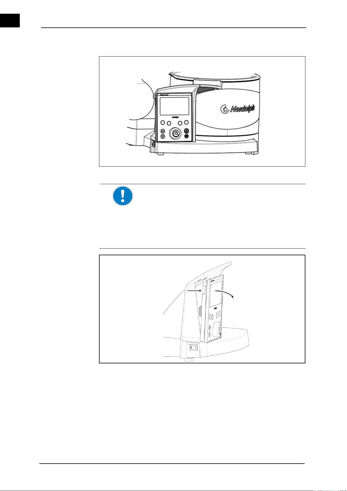
The control panel can be removed from the base unit.
The 1.3 m connecting cable between the control panel and the
base unit can be adjusted to the optimal length by a cable run and
reel.
The control panel can therefore be placed on a shelf and offers a
slight inclination for a view from above.
The control panel can be attached to a wall by pre-fabricated
holes or by an enclosed Velcro-connection.
Control panel
Remove the control
panel
4.9 Operating the control panel
Figure 4–31: Control panel (for Hei-VAP Precision)
1. Grasp the control panel on the left and pull it forward from the base unit.
Avoid pressure on the LCD screen.
40 Hei-VAP Value, Hei-VAP Advantage
Page 49
Set-up and Start-up
EN
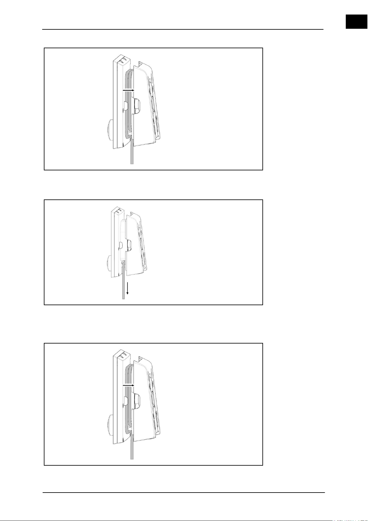
Control panel. Operation
2. The cable reel is surrounded by a shell.
3. Pull the control panel apart, so that the cable reel can be seen.
The cable reel is surrounded by a shell.
4. Reel in the cable to the desired length by wrapping the cable around the reel.
5. Press the shell to the control panel.
1. Pull the control panel apart, so that the cable reel can be seen.
2. Reel in the cable to the desired length by wrapping the cable around the reel.
3. Press the shell to the control panel.
Hei-VAP Value, Hei-VAP Advantage 41
Page 50
Set-up and Start-up
EN
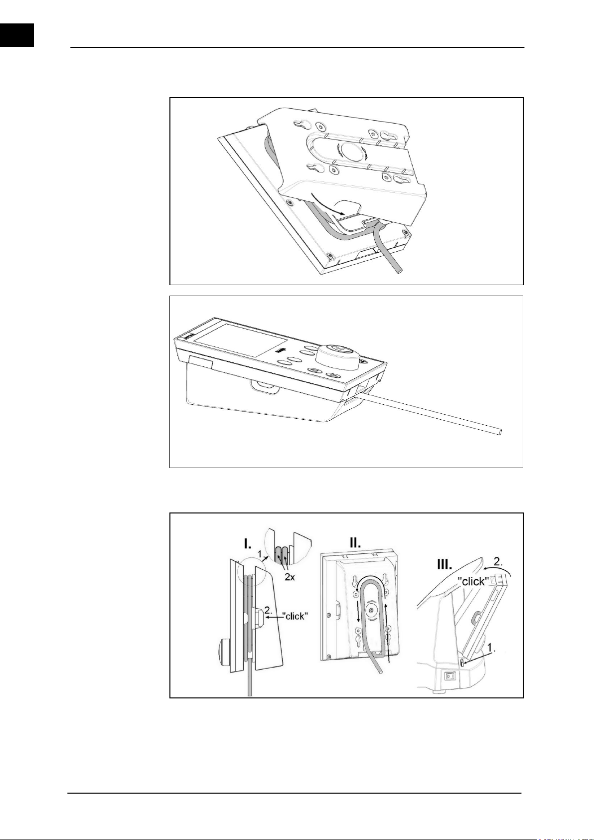
Attaching the control panel to a fixture
The shell can be turned by 180° as desired, in order to adjust the surface and view
to the control panel.
4. Place the control panel on the prefabricated guide rails that snap in and attach on
the wall or deposit it on a stable surface.
1. Attach the control panel back to the basic device.
42 Hei-VAP Value, Hei-VAP Advantage
Page 51
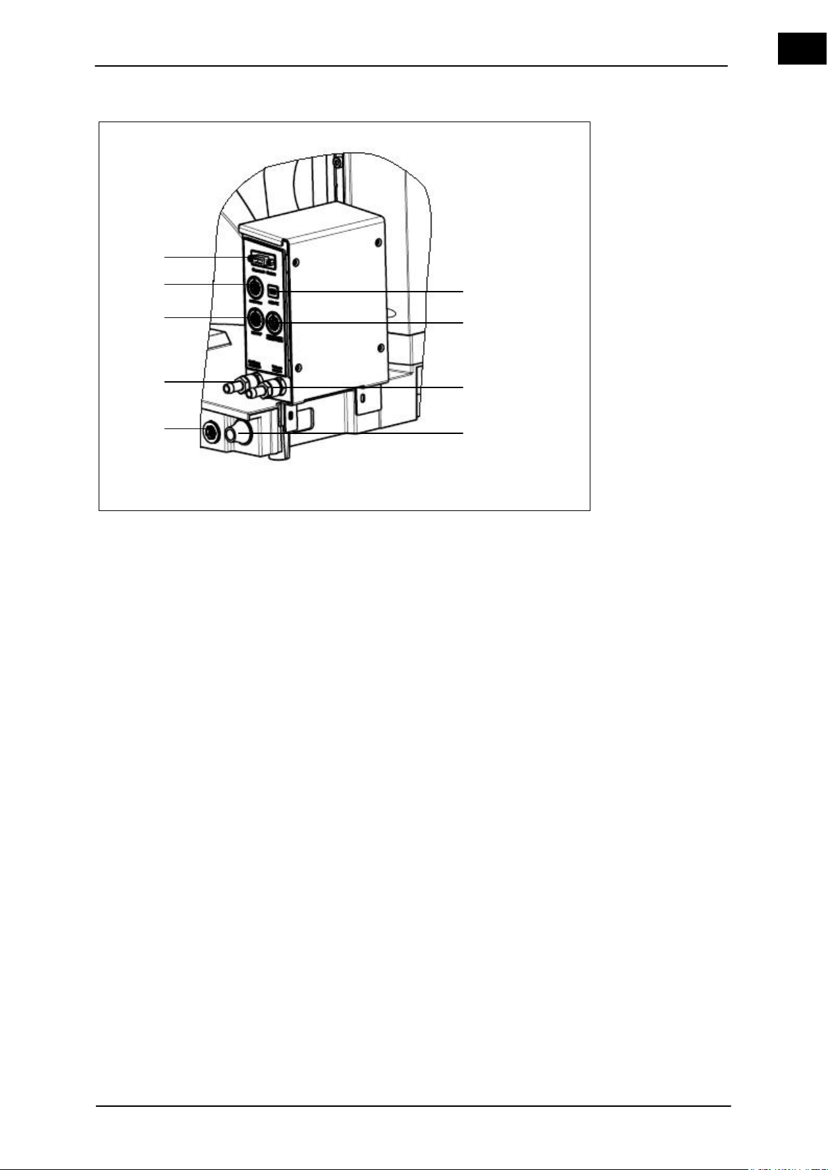
Set-up and Start-up
EN
1
USB PC connection
2
Vacuum pump/Vacuum valve connection
3
Suction side of vacuum
4
Connecting line outlet to the heating bath
5
Vacuum box connection
6
Ventilation / inert gas
7
Hei-VAP connection
8
Switch box connection
9
Bluetooth module
Hei-VAP Precision
with vacuum box
1 2 3
4 5 6
7 8 9
Figure 4–32: Vacuum box (for Hei-VAP Precision)
1. Place the vacuum box on the guiderails behind the heating bath. The vacuum box
brackets must be located above the holes.
2. Place the enclosed screws (2 pieces) in the holes with thread through the bracket of
the vacuum box.
3. Tighten the fastening screw.
4. Insert the necessary or applicable connections (2, 3, 4, 5, 7, 8) into the Vacuum box.
Hei-VAP Value, Hei-VAP Advantage 43
Page 52
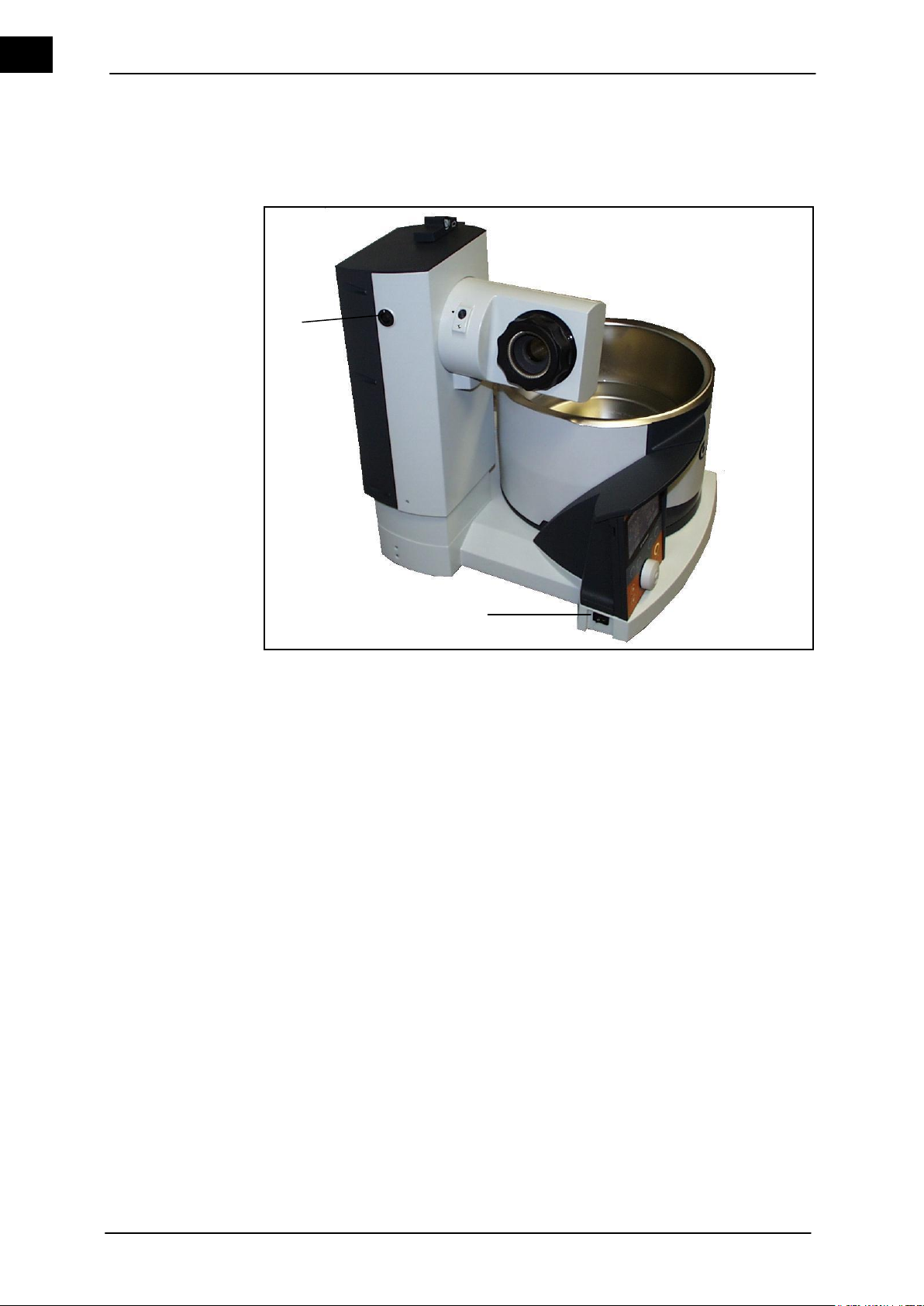
Switching on the base unit
EN
1
Power switch
2
Temperature sensor connector
2
1
5 Switching on the base unit
1. Switch on the base unit by pressing the toggle switch of the power switch.
2. The power switch of the base unit must be in the "1" position.
Figure 5–1: Base unit
44 Hei-VAP Value, Hei-VAP Advantage
Page 53
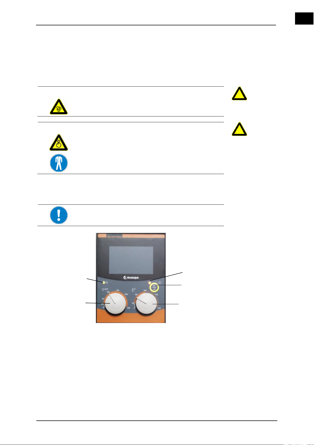
Operation of the Hei-VAP Value
EN
CAUTION
Unintentionally rotating drive!
Injuries to hands.
Verify that the rotation is displayed.
WARNING
Risk of injuries due to retracting or entrapment!
Risk of injury.
A risk of entanglement exists on the movable parts of the unit.
Wear suitable protective clothing for activities on the rotary
evaporator with goggles and gloves.
The Distillation rate (dT) can be increased by increasing the
speed of rotation.
1
Heater indicator light
2
Heating bath on/off
3
Control knob for the rated heating bath temperature
4
Control knob rotation
5
Unit on indicator light
Control panel
3
4
2
1
5
6 Operation of the Hei-VAP Value
The basic steps of operating the rotary evaporator Hei-VAP Value will be explained in
this chapter.
6.1 Set the rotation speed
The control dial for rotation is turned to the counterclockwise or left position to en-
sure it is turned off.
The unit is switched on.
Figure 6–1: Control panel Hei-VAP Value
1. Switch on the base unit by pressing the toggle switch of the power switch.
The power switch of the base unit must be in the "1" position. The unit on indicator
light (5) is illuminated.
2. Set the control knob rotation (4) to the desired speed.
Hei-VAP Value, Hei-VAP Advantage 45
Page 54
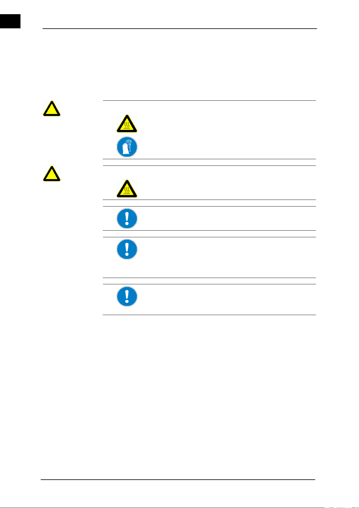
Operation of the Hei-VAP Value
EN
WARNING
Hot surfaces during the operation of the heating bath!
Burns.
Do not touch the interior and the upper edge of the heating
bath, the evaporator flask and the heating bath liquid.
Wear suitable heat protection gloves when changing the
evaporator flask.
CAUTION
Overheated heating bath!
Property damage and visual changes of the heating bath.
Never operate the heating bath without liquid.
The heating bath has a dry run protection. This must be reset
manually after being triggered (see Errors and Troubleshooting).
In order to achieve a high Distillation rate (dT), the temperature
difference between the heating bath and the steam temperature
must equal at least 20 K.
General: Doubling the temperature difference results in doubling
the Distillation rate (dT).
For rated temperatures above 100 °C, only suitable oil or polyethylene glycol (order No.: 515-31000-00; 5L; max. temp.: 240 °C)
may be used as heat transfer medium (observe safety data
sheets, see chapter 4.4.2).
Heating bath
6.2 Setting the heating bath temperature
The control dial for the heating bath is turned to the counterclockwise or left position
to ensure it is turned off.
The heating bath is filled with a heat transfer liquid.
The rotary evaporator is now operational and switched on at the power switch.
1. Switch on the heating bath by pressing the heating bath (Figure 6–1 (2) pushbutton
on the control panel.
2. Set the required temperature with the heating bath (Figure 6–1 (3) control knob
according to scale on the panel.
The control light of the heating bath (Figure 6–1 (1) shows that the heating bath is in
the heating phase. It must be illuminated in green to show active heating of bath.
6.3 Error messages
The error messages in this unit's flashing codes are only displayed in the event of a
malfunction. The flashing codes and their troubleshooting are explained in chapter 8,
"Errors and Troubleshooting“.
46 Hei-VAP Value, Hei-VAP Advantage
Page 55
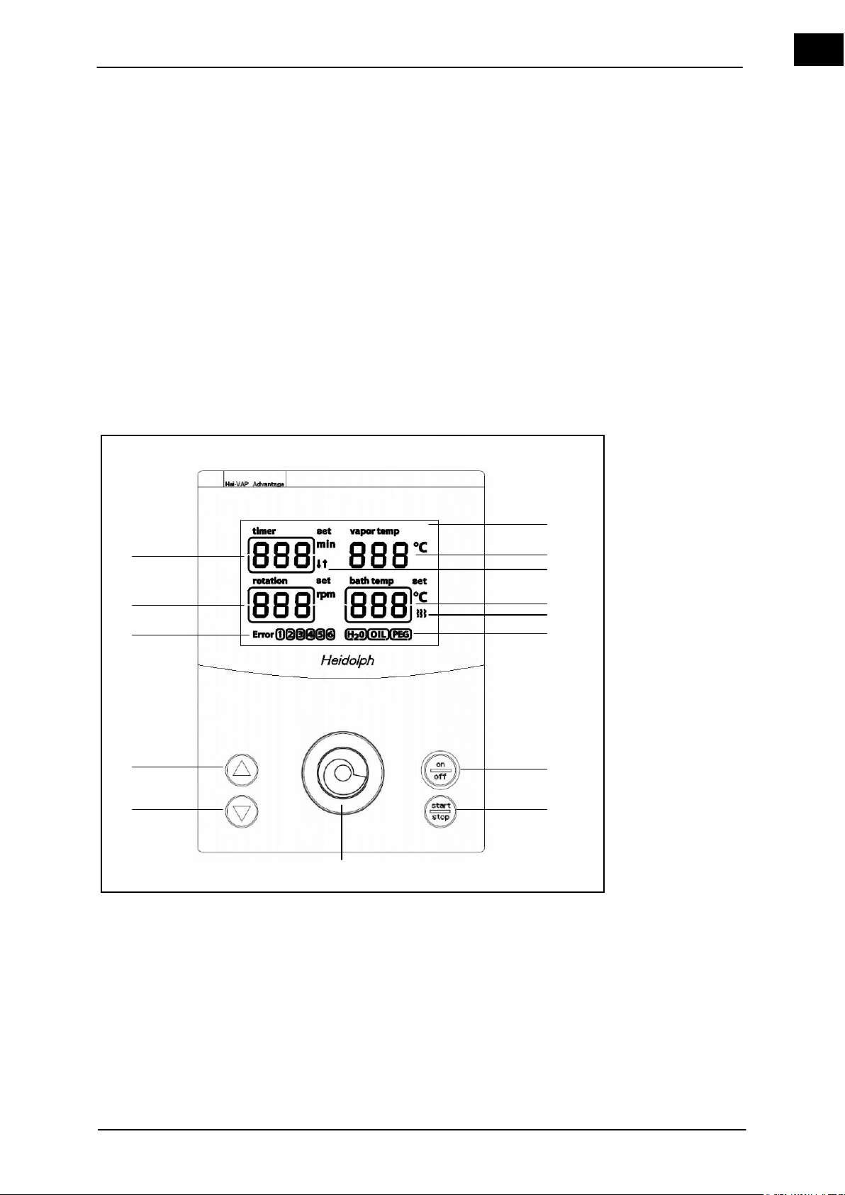
Operation of the Hei-VAP Advantage
EN
1
Display
8
Rotation start/stop
2
Boiling temperature [°C]
9
Hei-GUIDE
3
Timer icon
10
Lift down
4
Heating bath temperature [°C]
11
Lift up
5
Heating icon
12
Error code
6
Heating bath medium
13
Rotation speed [rpm]
7
Heating bath on/off
14
Timer [min]
Control panel
1
7
2
4 5 6 8 9
10
11
12
13
14
3
7 Operation of the Hei-VAP Advantage
The basic steps of operating the rotary evaporator Hei-VAP Advantage will be explained
in this chapter.
The parameters for the distillation are set and monitored via the digital control panel.
The set parameters are stored in the operating panel. The last used parameters will
appear after a restart or an extended break.
The starting screen is always the actual value display. The current actual values are
displayed in large numbers.
Turning the Hei-GUIDE knob will allow you to change between individual entries. The
particular selected entry is thereby illustrated and highlighted in a selection window. The
selection window shifts when turning the Hei-GUIDE clockwise ("heating bath medium">"bath temp (heating bath)“ -> "rotation (rotation)“ -> "timer“ (timer)).
The selected entry will be called up or engaged when pressing the Hei-GUIDE. The
desired value can be set when turning the Hei-GUIDE.
Several functions are controlled by the Hei-GUIDE and allows for toggling between the
different parameters.
Figure 7–1: Control panel Hei-VAP Advantage (with motor lift)
Hei-VAP Value, Hei-VAP Advantage 47
Page 56
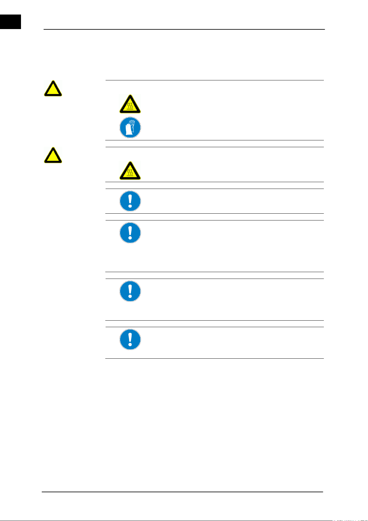
Operation of the Hei-VAP Advantage
EN
WARNING
Hot surfaces during the operation of the heating bath!
Burns.
Do not touch the interior and the upper edge of the heating
bath, the evaporator flask and the heating bath liquid.
Wear suitable heat protection gloves when changing the
evaporator flask.
CAUTION
Overheated heating bath!
Property damage and visual changes of the heating bath.
Never operate the heating bath without liquid.
The heating bath has a dry run protection. This must be reset
manually after being triggered (see Errors and Troubleshooting).
The unit has a power backup system. The heating bath is switched off when the power returns.
The unit maintains the last settings. The rated temperature of the
heating bath is displayed when the power is on.
The remaining residual time is stored by the timer. The timer is
triggered again after the power returns.
In order to achieve a high Distillation rate (dt), the temperature
difference between the heating bath and the vapor temperature
must equal at least 20 K.
General: Doubling the temperature difference results in doubling
the Distillation rate (dT).
For rated temperatures above 100 °C, only suitable oil or polyethylene glycol (order No.: 515-31000-00; 5L; max. temp.: 240 °C)
may be used as heat transfer medium (observe safety data
sheets, see chapter 4.4.2).
Heating bath medium
7.1 Setting the heating bath temperature
The heating bath is filled with heat transfer liquid.
7.1.1 Select heating bath medium
1. Switch on the base unit by pressing the power switch (Figure 5–1 (1)).
The toggle switch of the base unit must be in the "1" position.
2. Activate the heating bath medium (OIL or H2O) (6) with the support of the selection
window by using the rotary pushbutton Hei-GUIDE (9).
3. The selection window flashes when pressing the rotary pushbutton Hei-GUIDE (9).
4. Pressing the Hei-GUIDE (9) again takes over the selected heating bath liquid. The
selection window jumps to "bath temp" and flashes.
The target temperature is displayed when switching the unit on again. The selection
window is on the last selected medium. Confirming the medium and confirming the
48 Hei-VAP Value, Hei-VAP Advantage
target temperature twice will take over the last settings.
The target value is set at 20 °C after a previous change of the heating bath medium
from "OIL“ to "H
O“, if a target value of more than 100 °C was set.
2
Page 57
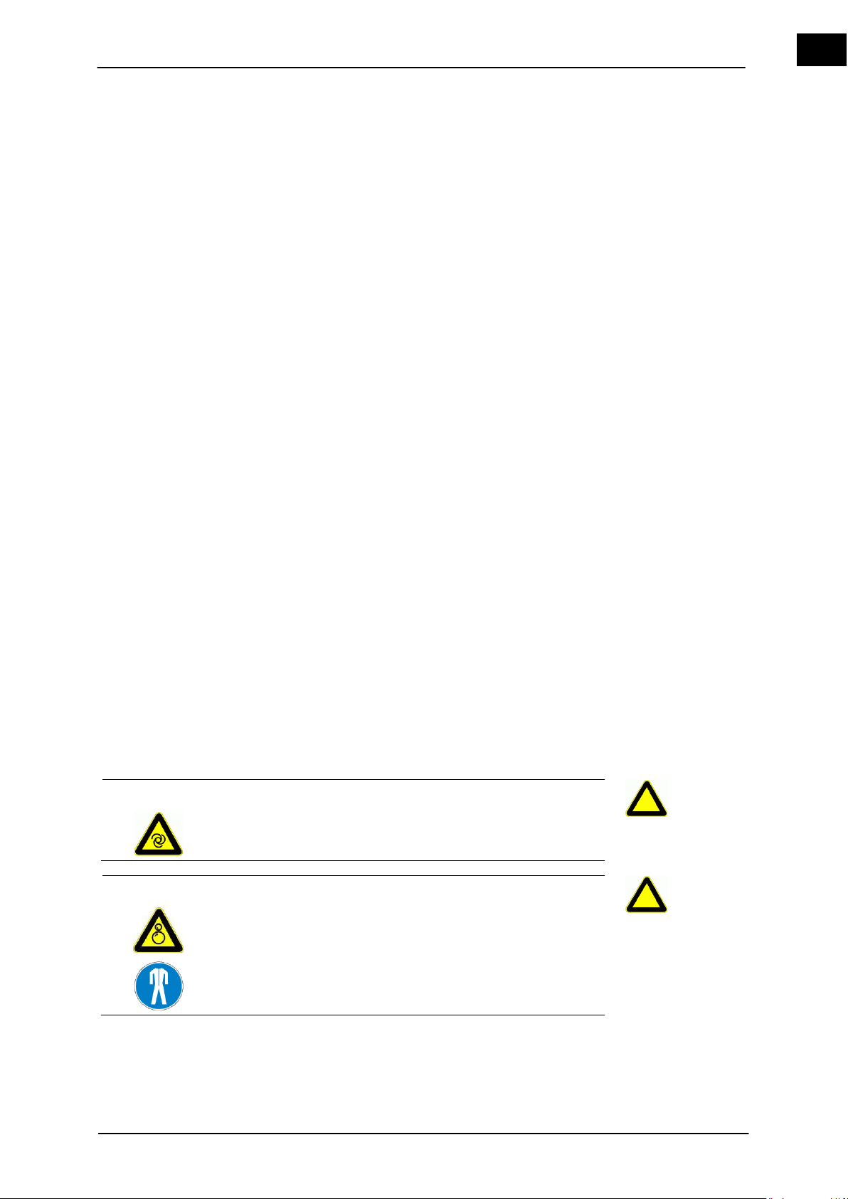
Operation of the Hei-VAP Advantage
EN
CAUTION
Unintentionally rotating drive!
Injuries to hands.
Verify that the rotation is displayed.
WARNING
Risk of injuries due to retracting or entrapment!
Risk of injury.
A risk of entanglement exists on the movable parts of the unit.
Wear suitable protective clothing for activities on the rotary
evaporator with goggles and gloves.
Heating bath temperature
The last set medium will be taken over after 10 seconds of inactivity of the HeiGUIDE. The window then jumps to “rotation” at rotation "off".
7.1.2 Setting the heating bath temperature
Select the heating bath medium via the control panel.
1. Activate the heating bath temperature display with the aid of the selection window by
using the rotary pushbutton controller Hei-GUIDE (9).
2. The selection window flashes when pressing the rotary pushbutton controller Hei-
GUIDE (9). The current target temperature will be displayed. This value can be
changed.
Display values: 20 °C to +210 °C in single °C steps
3. Turn the rotary pushbutton controller Hei-GUIDE (9) to set the display value to the
desired target temperature.
If the target temperature is exceeded past 100 °C, the selection window will be displayed and a frame around the OIL (6) display will flash.
Pressing the button again confirms that a suitable medium (OIL) is available in the
heating bath.
The temperature display flashes and can be set to the desired temperature.
4. Pressing the Hei-GUIDE (9) again takes over the reset value and the selection window is permanently illuminated.
The actual temperature is displayed after confirmation.
The evaporator responds immediately, if the heating bath is switched on.
If the target temperature of more than 100 °C is changed to less than 100 °C, the
display OIL (6) remains until the next activation.
The frame is faded out after 10 seconds of inactivity of the Hei-GUIDE.
5. Switch on the heating bath by pressing the pushbutton heating bath on/off (7).
The heating bath indicator light indicates that the heating bath is switched on. It
must be illuminated in green.
The heating icon (5) next to the "bath temp" display is illuminated, if the heating bath
is in the heating phase.
7.2 Set the rotation speed
Hei-VAP Value, Hei-VAP Advantage 49
Page 58

Operation of the Hei-VAP Advantage
EN
The rotation remains in the connecting solution between the control panel and the evaporator.
The Distillation rate (dT) can be increased by increasing the
speed.
The set target value is automatically assumed after 10 s.
If the rotation has not started after 10 seconds of inactivity of the
Hei-GUIDE, the frame jumps to the Rotation parameter, the
target value and the frame will be displayed until the rotation is
started by the rotation pushbutton "start/stop“.
The selection window is activated by the rotation speed at rotation
"off" and the target value of the rotation, the target value for "timer" (if selected) and the actual values for "bath temp" and "vapor
temp" will be displayed.
A selection window will not be displayed at rotation "on", but only
the current values.
Rotation speed
Boiling temperature
The unit is switched on.
The rotary evaporator is operational and switched on at the power switch.
1. Activate the rotation display with the aid of the selection window by using the rotary
pushbutton controller Hei-GUIDE (9).
2. Pressing the rotary pushbutton Hei-GUIDE (9) makes it possible to change the
value. The selection window flashes.
3. Turn the rotary pushbutton knob Hei-GUIDE (9) to set the display value to the desired target speed.
The evaporator responds immediately, if the rotation has been switched on via the
Rotation start (8) pushbutton.
If timing has not been set, the time will be counted upward after pressing the Rota-
tion start (8) pushbutton. An arrow "up" will be inserted under the min display.
4. Switch on the rotation by pressing the Rotation start (8) pushbutton. The speed
display shows the actual value.
7.3 Calculating the boiling temperature (Hei-VAP Advantage)
The unit is switched off.
The vapor temperature sensor (optional) is connected to the temperature sensor
socket (Figure 5–1 (2))
Switch the unit on.
The vapor temperature appears on the screen of the rotary evaporator "vapor temp", if
the vapor temperature sensor is connected.
50 Hei-VAP Value, Hei-VAP Advantage
Page 59

Operation of the Hei-VAP Advantage
EN
A set timer is displayed by inserting an arrow "down" below the
min. display.
If a timer is not set, the timer is always counted upward. The
arrow "up" is inserted.
The screen is reset to value "---" when activating the Hei-GUIDE
(turning or pressing), the frame flashes, and the value can be
change or confirmed.
If value "---" is confirmed by pressing the Hei-GUIDE, the timer
will count the run time upward after the start of the rotation. The
up arrow will be illuminated. This value and the frame will flash
when reaching the maximum value of "999". The process will
continue.
The value is set at zero and the "timer" will again count upward
when activating the Hei-GUIDE (turning or pressing), if the
process has not been stopped.
An upgrade from the evaporator model Hei-VAP Advantage to
evaporator model Hei-VAP Precision is possible by changing the
control panel and adding a vacuum box.
Timer
7.4 Timing functions
7.4.1 Timer
The timer function stops the distillation after a set period.
1. Activate the timing display with the aid of the selection window by using the rotary
pushbutton controller Hei-GUIDE (9).
2. The selection window flashes when pressing the rotary pushbutton Hei-GUIDE (9).
The value can therefore be adjusted. A time between 1 and 999 minutes can be selected by turning the Hei-GUIDE (9).
3. Turn the rotary pushbutton controller Hei-GUIDE (9) to set the display value to the
desired timing value.
4. Pressing the Hei-GUIDE (9) again takes over the selected new value. The evaporator responds immediately and the time is counted backward.
5. An arrow "down" (3) will be inserted under the minute display.
The time is running backwards at the start of the rotation with the Rotation start (8)
pushbutton. The distillation is interrupted after completing the set time.
the timer display shows "000" with a flashing frame
Motor lift version:
The rotation is switched off.
The lift is raised (only Hei-VAP Advantage, Hei-VAP Precision).
The heating bath is switched off.
Hand lift version
The rotation changes to 20 rpm till manual intervention by the user.
The heating bath is switched off.
7.5 Error messages
Error messages are only displayed in the event of an error. The error codes 1 to 6 and
their troubleshooting are explained in chapter 8, "Errors and Troubleshooting“.
7.6 Upgrading
Hei-VAP Value, Hei-VAP Advantage 51
Page 60

EN
Error / message
Cause
Remedy
Unit cannot be switched on
Main plug not connected to the main power supply
Connect the main plug
with the power supply
Fuses defective or blown fuse
Replace fuses
(see chapter 9.2)
No heating function
Master switch is deactivated
Activate main switch
Fuses defective or blown fuse
Replace fuses
(see chapter 9.2)
Master switch is defective
Contact service
The connecting cable of the heating bath is
not connected.
Connect the connecting
cable of the heating bath
The heater of the heating bath is defective
Contact service
The maximum temperature limiter responded
If the medium was in the
heating bath: Let the
heating bath cool and reset the maximum temperature limiter
If the medium was not in
the heating bath: Contact
service
Drive unit is not rotating
Master switch is defective
Contact service
Speed controller is on the left stop
(Hei-VAP value)
Turn the speed controller
to the right
Drive unit is defective
Contact service
Fuses defective or blown fuse
Replace fuses
(see chapter 9.2)
Motor lift is not functioning
Master switch is deactivated
Activate main switch
Master switch is defective
Contact service
Fuses defective or blown fuse
Replace fuses
(see chapter 9.2)
Lift is at end stop
Activate other arrow key
Mechanical system / motor is defective
Contact service
Height stop is not set accurately
Perform height adjust-
ment
(see chapter 4.5.7)
8 Errors and Troubleshooting
8.1 General errors
52 Hei-VAP Value, Hei-VAP Advantage
Page 61
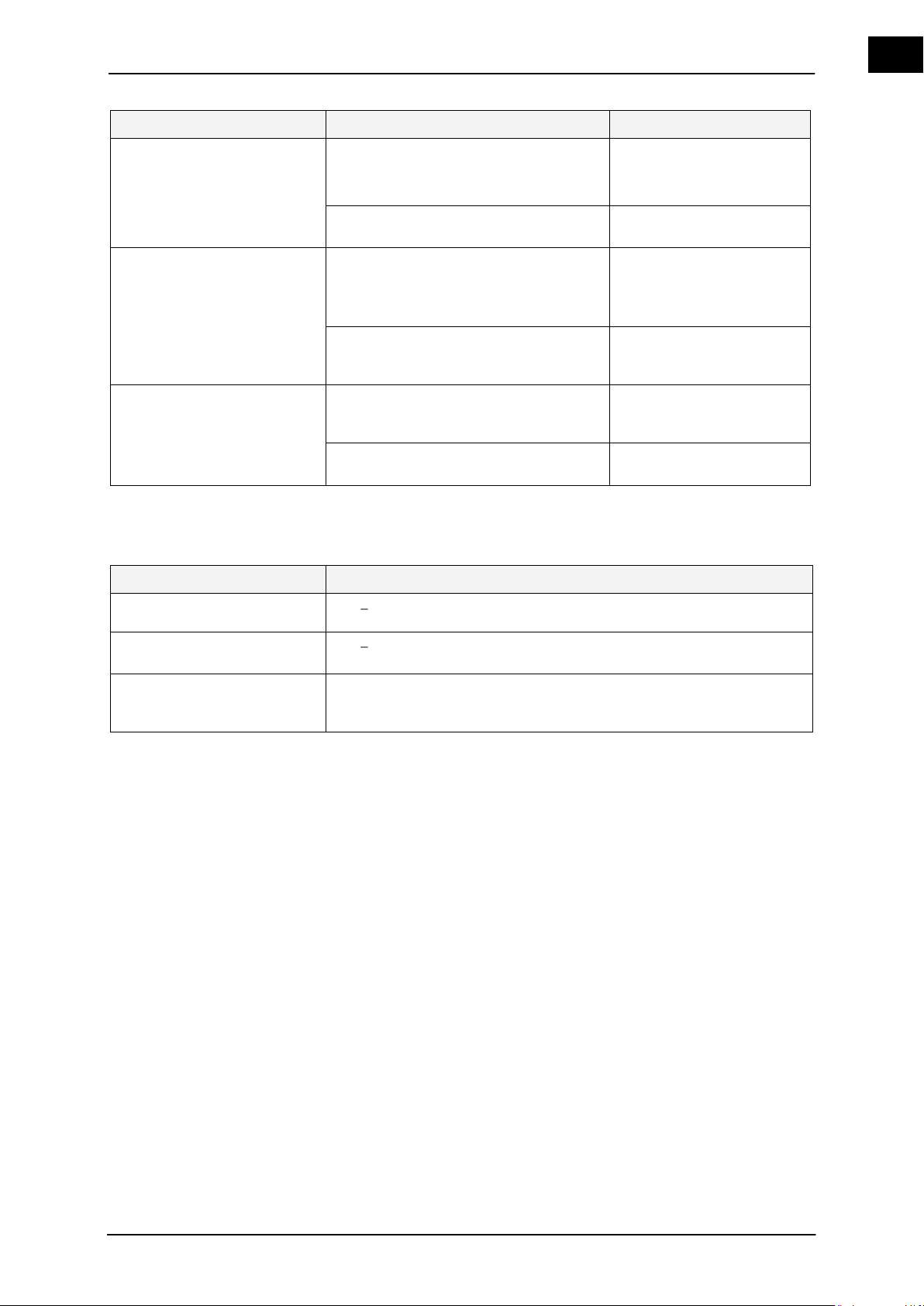
EN
Error / message
Cause
Remedy
No evacuation
Power switch Rotavac vario control or
Rotavac vario tec is not activated.
Vacuum valve is defective.
Activate the power switch
Fuses defective or blown fuse
Replace fuses
(see chapter 9.2)
Insufficient vacuum
System leaks
Check seals, tubing and
connections
Check stopcocks, grease
if necessary
Vacuum pump is defective
Observe manufacturer's
instructions of the vacuum pump
Unit suddenly switches off
(Hei-VAP Precision and
Hei-VAP Advantage)
Timer is programmed
Check and switch off the
timer, if necessary
(see chapter 7.4.1)
Fuses defective or blown fuse
Replace fuses
(see chapter 9.2)
Table 8-1: Troubleshooting table
Additional conditions
Reaction
Vapor sensor is defective
The actual value curve is displayed “---“ instead of the vapor tem-
perature.
The vapor sensor is not connected
The vapor temperature is not displayed in the actual value display
Heater can only be activated at
>0 °C (observe acetone, dry
ice)
8.2 Additional conditions
Table 8-2: Additional conditions
Hei-VAP Value, Hei-VAP Advantage 53
Page 62

EN
Error / message
(flashing code)
Cause
Remedy
**
No data received at all for 3
seconds
Cable connection between the control
panel and the base unit was disconnected. An error occurred in the data
bus.
Restore the cable con-
nection between the control panel and the base
unit. Switch the power
switch off and on again.
Contact service
***
Heater is defective, i.e. the over-
heating protection was triggered.
If the medium was in the
heating bath: Let the
heating bath cool and reset the maximum temperature limiter
If the medium was not in
the heating bath: Contact
service
HB safety temperature (+5 K) is
exceeded
Contact service
Heating bath is completely evapo-
rated.
Deactivate the unit
Check if the maximum
temperature limiter has
responded. If yes, reset
(see chapter 9.1.1)
Fill in heat transfer fluid
Heating bath sensor variance
> 10 K
Contact service
Sensor monitoring via hardware
HB sensor broken or short circuited
Contact service
The temperature sensor for moni-
toring the heating bath control is
broken or the temperature of the
medium in the heating bath is
> 217 °C.
Cool down the heating
bath medium
Contact service
The temperature sensor for the
heating bath control is short circuited or the temperature is below
0 °C
Contact service
****
Potentiometer temp. is defective
(value)
Contact service
Potentiometer speed is defective
(value)
Contact service
*****
Motor is not rotating:
Motor overload shutdown
Deactivate the unit
Stop drive unit for cooling
down
Contact service
8.3 Hei-VAP Value
Table 8-3: Troubleshooting table - Hei-VAP Value
54 Hei-VAP Value, Hei-VAP Advantage
Page 63

EN
8.4 Hei-VAP Advantage
Error / message
(error label)
Cause
Remedy
1
The transportation protection device is still
activated.
(only motor lift version)
Please raise the lift and
briefly switch the unit off
and then on again.
No data received at all for 3
seconds
Cable connection between the control
panel and the base unit was disconnected. An error occurred in the data
bus.
Restore the cable con-
nection between the control panel and the base
unit. Switch the power
switch off and on again.
Contact service
3
Heater is defective, i.e. the over-
heating protection was triggered.
If the medium was in the
heating bath: Let the
heating bath cool and reset the maximum temperature limiter
If the medium was not in
the heating bath: Contact
service
Heating bath safety temperature
(+5 K) is exceeded
Contact service
Heating bath is completely evapo-
rated.
Deactivate the unit
Check if the maximum
temperature limiter has
responded. If yes, reset
(see chapter 9.1.1)
Fill in heat transfer fluid
Heating bath sensor variance
> 10 K
Contact service
Sensor monitoring via hardware
HB sensor broken or short circuited
Contact service
The temperature sensor for moni-
toring the heating bath control is
broken or the temperature of the
medium in the heating bath is
> 217 °C.
Cool down the heating
bath medium
Contact service
The temperature sensor for the
heating bath control is short circuited or the temperature is below
0 °C
Contact service
5
Motor is not rotating:
Motor overload shutdown
Deactivate the unit
Stop drive unit for cooling
down
Contact service
Table8-4: Troubleshooting table - Hei-VAP Advantage
Hei-VAP Value, Hei-VAP Advantage 55
Page 64

EN
Missing component
Description and response
of the evaporator
Remedy
Temperature sensor
T boiling
The temperature sensor for calculating the
boiling temperature is not connected:
The vapor temperature is not dis-
played
Connect component
Reset via power off/on
The rotary evaporator is checked after "power on" in an initialization phase for connected components. The function scope of the rotary evaporator is based on the connected units.
Table 8-5: Missing components
56 Hei-VAP Value, Hei-VAP Advantage
Page 65
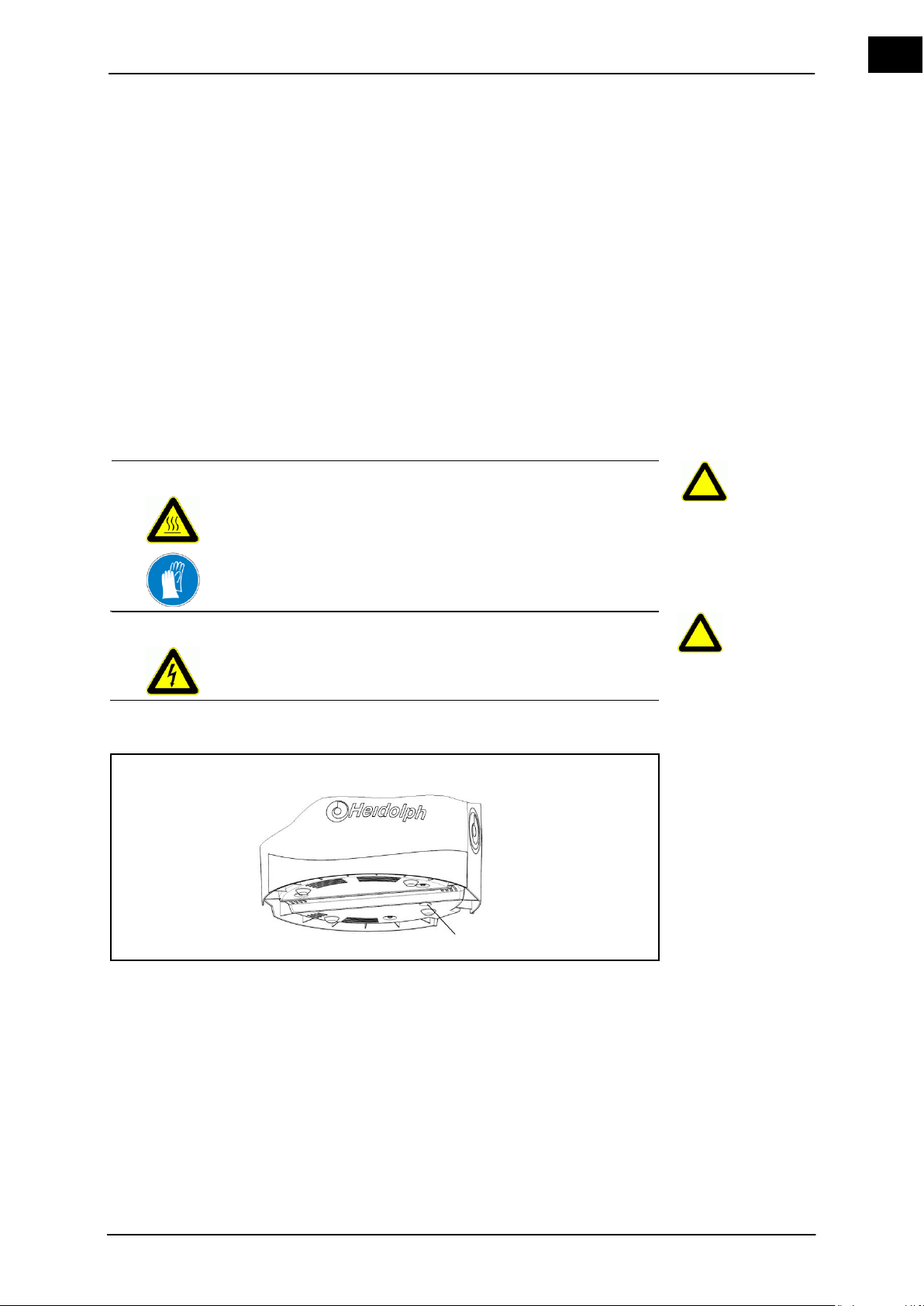
EN
9 Maintenance, cleaning, service
WARNING
Hot surfaces!
Burns.
Cool the heating bath.
WARNING
Verify that the basic device is only plugged to or unplugged from
the heating bath if the main switch is switched off and/or the main
power supply is disconnected.
Maintenance
Maximum temperature limiter
Maximum temperature limiter
1
9.1 Maintenance
Only use genuine parts approved by the manufacturer!
The vapor tube and PTFE 26 vacuum seal must be routinely serviced.
1. Remove and clean the vapor tube and the PTFE 26 vacuum seal (see chapter
4.5.2).
2. Check the PTFE 26 vacuum seal for damages and wear, replace if necessary.
9.1.1 Resetting the maximum temperature limiter
In the event that the temperature controller malfunctions and the heating bath temperature exceeds the maximum temperature of 250 °C, the maximum temperature limiter will
switch off the heating bath.
The heating bath is cooled and disconnect from power-supply. Power-switch off.
1. Remove the heating bath liquid from the heating bath.
Figure 9–1: Maximum temperature limiter
2. Press the maximum temperature limiter (1), possibly with a pointed object.
Hei-VAP Value, Hei-VAP Advantage 57
Page 66
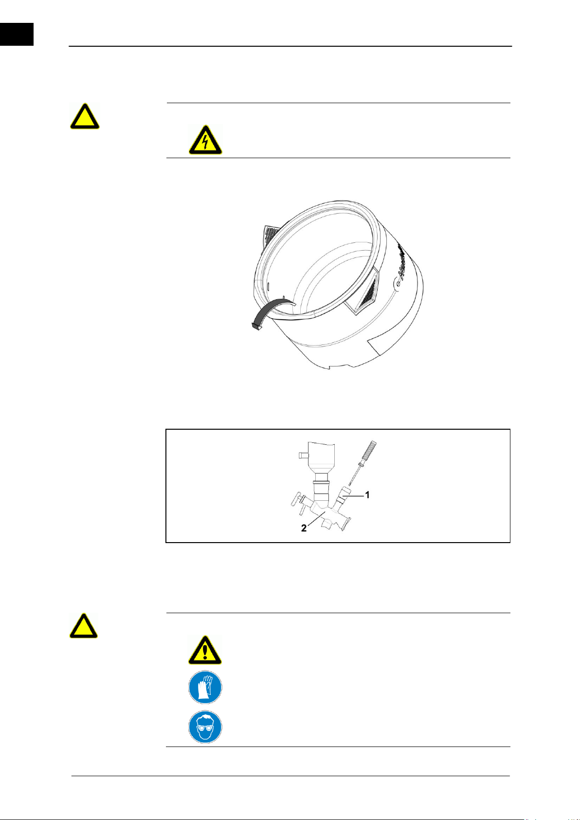
Maintenance, cleaning, service
EN
WARNING
Verify that the basic device is only plugged to or unplugged from
the heating bath if the main switch is switched off and/or the main
power supply is disconnected.
1
Valve
2
Center piece G6
WARNING
Glass breakage!
Cuts.
Work carefully; do not readjust the adjusting screw too much.
Evacuating the
heating bath
Vacuum seal
9.1.2 Evacuate the heating bath
1. The heating bath is cooled and disconnect from power-supply. Power-switch off.
2. Take the heating bath from off the device.
3. The edge of the heating bath is designed to easily evacuate the heating bath.
Evacuate the heating bath.
9.1.3 Readjust the vacuum seal (glassware set G6)
Figure 9–2: Readjust the vacuum seal - glassware set G6
The seal in the valve (1) can be readjusted with a screwdriver.
58 Hei-VAP Value, Hei-VAP Advantage
Page 67
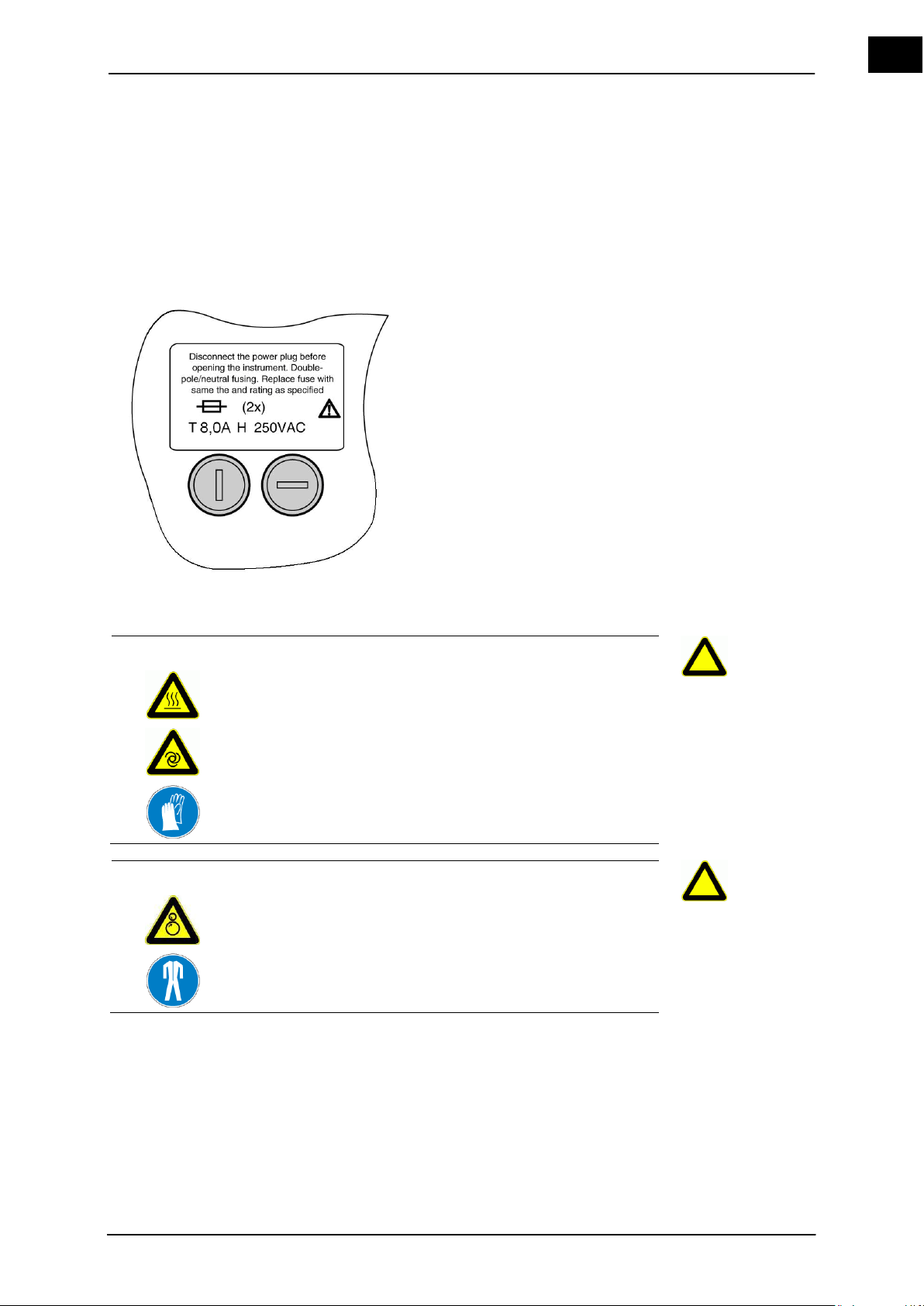
EN
CAUTION
The drive unit and the heating bath may be switched on accidentally!
Injuring and burning hands.
Verify that the power switch for the base unit and the heating
bath is switched off via the pushbutton.
WARNING
Risk of injuries due to retracting or entrapment!
Risk of injury.
A risk of entanglement exists on the movable parts of the unit.
Wear suitable protective clothing for activities on the rotary
evaporator with goggles and gloves.
Fuse
1. Screw the valve into the G6 center piece (2) up to the stop.
2. Turn the adjusting screw clockwise until a white ring can be seen at the shaft of the
glass.
9.2 Replacing the fuses
The fuses are located on the bottom of the unit.
Figure 9–3: Fuse on the bottom of the unit
1. Disconnect the unit from the power plug.
2. Remove evaporating flask.
3. Cool the heating bath liquid and remove the heating bath from the base unit by
disconnecting the power plug.
4. Carefully tilt the unit and pour out the bath media.
5. Dry the bath and turn it over with the bottom facing upward.
6. Remove the defective fuse by using a screwdriver.
7. Insert a suitable new fuse and tighten with a screwdriver.
The fuse has been replaced. The unit can be returned to active heating operation.
Hei-VAP Value, Hei-VAP Advantage 59
Page 68

Maintenance, cleaning, service
EN
CAUTION
Damages due to corrosive cleaning agents!
Damages on the surface of the unit.
Use only mild soap solutions. Never use chlorine bleach or
cleaning agents that are chlorine based. Never use abrasives, ammonia, cleaning rags or cleaning agents with metal
parts.
In Germany,
Austria and Switzerland:
Tel:
0800-HEIDOLPH or
0800-43 4 3657 4 (Free call)
+49 (0) 91 22 99 20 69
Fax:
+49 (0) 91 22 99 20 65
E-mail:
Addresses and
telephone numbers
9.3 Cleaning
Wipe the surfaces of the unit with a damp cloth (mild soap solution).
9.4 Service
Your unit is not working?
1. Please contact Heidolph Instruments or your authorized
Heidolph Instruments dealer via telephone or email.
2. After consulting with a Heidolph service employee:
Copy and complete a declaration of non-objection from these instructions, if ne-
cessary
Package the unit for shipping per the recommended methods of the service de-
partment and mail to the following including the declaration of non-objection:
Heidolph Instruments GmbH & Co. KG
Vertrieb Labortechnik
Walpersdorfer Str. 12
91126 Schwabach / Germany
60 Hei-VAP Value, Hei-VAP Advantage
Page 69
EN
10 Dismantling, storage, disposal
CAUTION
Unintentionally rotating drive!
Injuries to hands.
Verify that the rotation is displayed.
WARNING
Risk of injuries due to retracting or entrapment!
Risk of injury.
A risk of entanglement exists on the movable parts of the unit.
Wear suitable protective clothing for activities on the rotary
evaporator with goggles and gloves.
WARNING
Hot surfaces!
Scalding and burns.
Let the heating bath and glass devices cool.
WARNING
Glass breakage!
Cuts.
Work carefully.
WARNING
Glass breakage!
Cuts.
Work carefully.
Woulff bottle
10.1 Disassembly
Dismantle the glassware sets in reverse sequence of the assembly (see chapter
4.5).
10.1.1 Remove the Woulff bottle
Remove the Woulff bottle in reverse sequence of the assembly (see chapter 4.5.13).
Hei-VAP Value, Hei-VAP Advantage 61
Page 70

Dismantling, storage, disposal
EN
WARNING
Hot surfaces!
Scalding and burns.
Cool the heating bath.
Coolant /
vacuum
Remove the heating bath
Where?
How?
Where?
How?
Disposal
10.1.2 Disconnecting the coolant / vacuum
1. Verify that the coolant and vacuum supply is switched off and that the system is at
2. Disconnect the tubes from the condenser and drain coolant safely into a storage
10.1.3 Remove the heating bath
Remove the heating bath in reverse sequence of the assembly (see chapter 4.4.1).
10.2 Storage
Evaporator
The unit may be stored in a dry location.
Store the unit in the original packaging (only possible with the transportation protec-
Close the packaging with adhesive tape.
Glassware set
The glassware set may be stored in a dry location.
Empty and clean the glassware set.
Store the glassware set in the original packaging.
Close the packaging with adhesive tape.
atmospheric pressure.
container.
tion device attached).
62 Hei-VAP Value, Hei-VAP Advantage
10.3 Disposal
Properly dispose of the unit according to the valid national and legal regulations
pertaining to disposal of used laboratory equipment.
Page 71
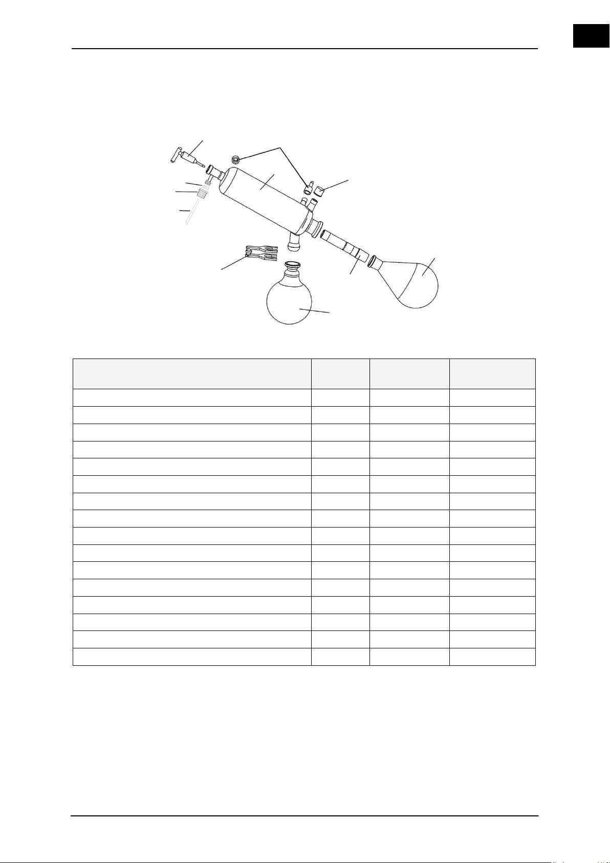
EN
11 Accessories, spare parts
Order description
Position
Order No.
Piece at delivery
Threaded fitting GL 18
1
23-09-03-01-24
1
Evaporator flask 1,000 ml, NS 29/32
2
514-74000-00
1
Evaporator flask 1,000 ml, NS 24/40
2
514-74000-05
(1)
Vapor tube NS 29 / 32
3
514-00000-01
1
Vapor tube NS 24 / 40
3
514-00020-03
(1)
Receiving flask 1000 ml, S 35/20
4
514-84000-00
1
Receiving flask 1000 ml, S 35/20, plastic coated
4
514-84000-02
(1)
Condenser clamp S 35/20
5
515-42000-00
1
Inlet tube (PTFE-) 3.5/4.5x600
6
23-30-01-04-72
1
Threaded fitting GL10 red
7
23-30-01-04-69
1
Seal O-ring 3.2x2.5
8
23-08-06-03-26
1
Inlet pipe (stopcock)
9
514-51000-00
1
Threaded fitting GL 14
10
23-09-03-01-27
3
Connector for the threaded fitting GL 14
10
11-300-005-22
3
Condenser G1
11
514-00100-00
1
Condenser G1B, plastic coated
11
514-00110-00
(1)
9 2 4 3 5 1 8 7 6
10
11
11.1 Glass devices
Figure 11–1: Glassware set G1
Table 11-1: Glassware set G1
Hei-VAP Value, Hei-VAP Advantage 63
Page 72
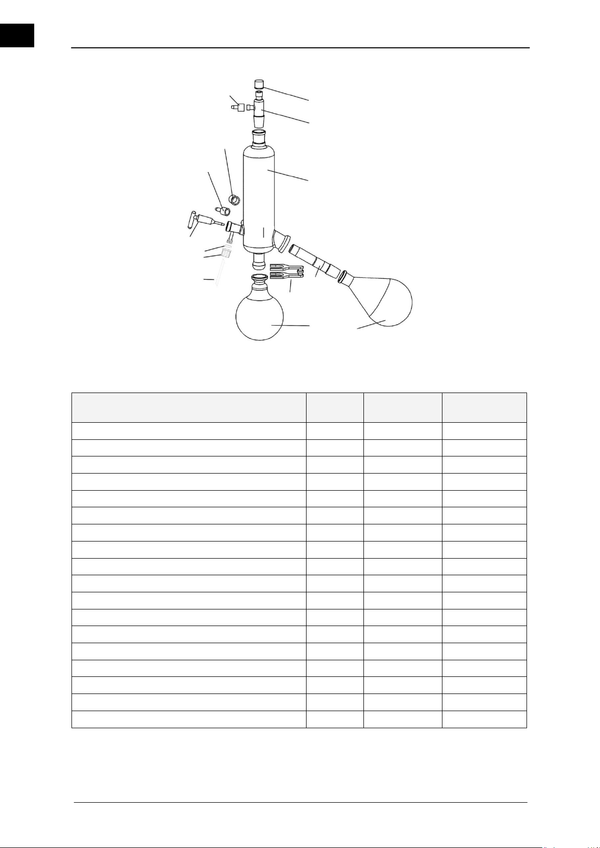
EN
Order description
Position
Order No.
Piece at delivery
Threaded fitting GL 18
1
23-09-03-01-24
2
Vacuum fitting NS 29 / 32
2
514-00001-00
1
Condenser G3
3
514-00300-00
1
Condenser G3B, plastic coated
3
514-00310-00
(1)
Evaporator flask 1,000 ml, NS 29/32
4
514-74000-00
1
Evaporator flask 1,000 ml, NS 24/40
4
514-74000-05
(1)
Vapor tube NS 29 / 32
5
514-00000-01
1
Vapor tube NS 24 / 40
5
514-00020-03
(1)
Condenser clamp S 35/20
6
515-42000-00
1
Receiving flask 1000 ml, S 35/20
7
514-84000-00
1
Receiving flask 1000 ml, S 35/20, plastic coated
7
514-84000-02
(1)
Inlet tube (PTFE-) 3.5/4.5x600
8
23-30-01-04-72
1
Threaded fitting GL10 red
9
23-30-01-04-69
1
Seal O-ring 3.2x2.5
10
23-08-06-03-26
1
Inlet pipe (stopcock)
11
514-51000-00
1
Threaded fitting GL 14
12
23-09-03-01-27
3
Connector for the threaded fitting GL 14
13
11-300-005-22
3
Condenser mounting
569-00050-00
1
1 2 3 4 5 7 6 8 9
10
11
12/13
1
12/13
Figure 11–2: Glassware set G3
Table 11-2: Glassware set G3
64 Hei-VAP Value, Hei-VAP Advantage
Page 73
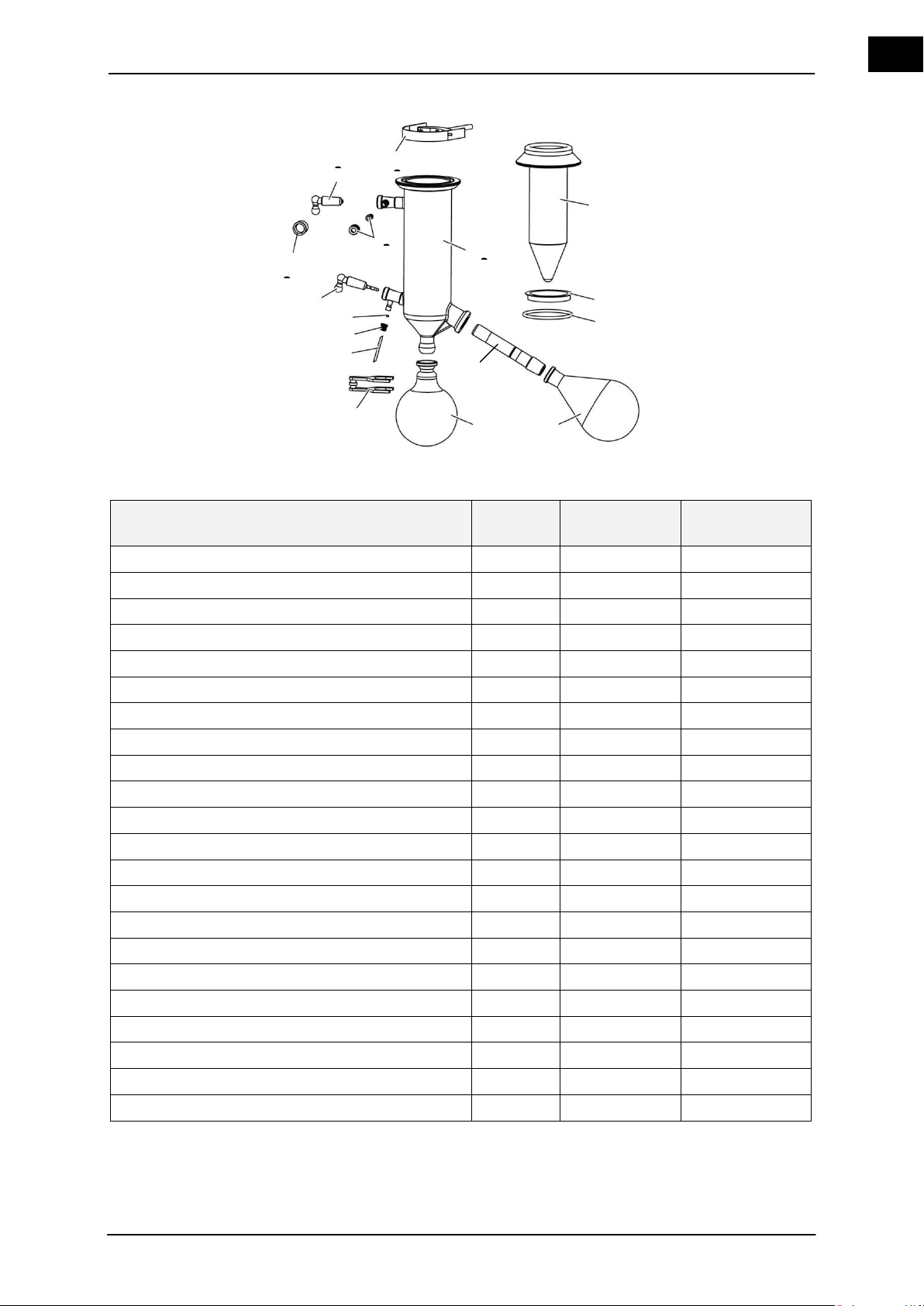
EN
Figure 11–3: Glassware set G5
Order description
Position
Order No.
Piece at delivery
Insert cold trap
1
514-00501-00
1
Centering ring
2
23-30-01-04-88
1
Seal G5 (silicone)
3
23-30-01-01-88
(1)
Gasket G5
3
23-30-01-01-39
1
Evaporator flask 1,000 ml, NS 29/32
4
514-74000-00
1
Evaporator flask 1,000 ml, NS 24/40
4
514-74000-05
(1)
Vapor tube NS 29 / 32
5
514-00000-01
1
Vapor tube NS 24 / 40
5
514-00020-03
(1)
Condenser clamp S 35/20
6
515-42000-00
1
Receiving flask 1000 ml, S 35/20
7
514-84000-00
1
Receiving flask 1000 ml, S 35/20, plastic coated
7
514-84000-04
(1)
Inlet tube (PTFE-) 3.5/4.5x600
8
23-30-01-04-72
1
Threaded fitting GL10 red
9
23-30-01-04-69
1
Seal O-ring 3.2x2.5
10
23-08-06-03-26
1
Inlet pipe (stopcock)
11
514-51000-00
1
Threaded fitting GL 14
12
23-09-03-01-27
2
Connector for the threaded fitting GL 14
12
11-300-005-22
2
Threaded fitting GL 18
13
23-09-03-01-24
1
Stopper NS 19 / 38 (stopcock)
14
15-003-003-24
1
Holder, complete
15
569-00051-00
1
Liner cold trap
16
514-00500-00
1
Liner cold trap, plastic coated
16
514-00510-01
(1)
1
2
3 4 7 6 8 9 10
11
13
14
15
12
16
5
Table 11-3: Glassware set G5
Hei-VAP Value, Hei-VAP Advantage 65
Page 74
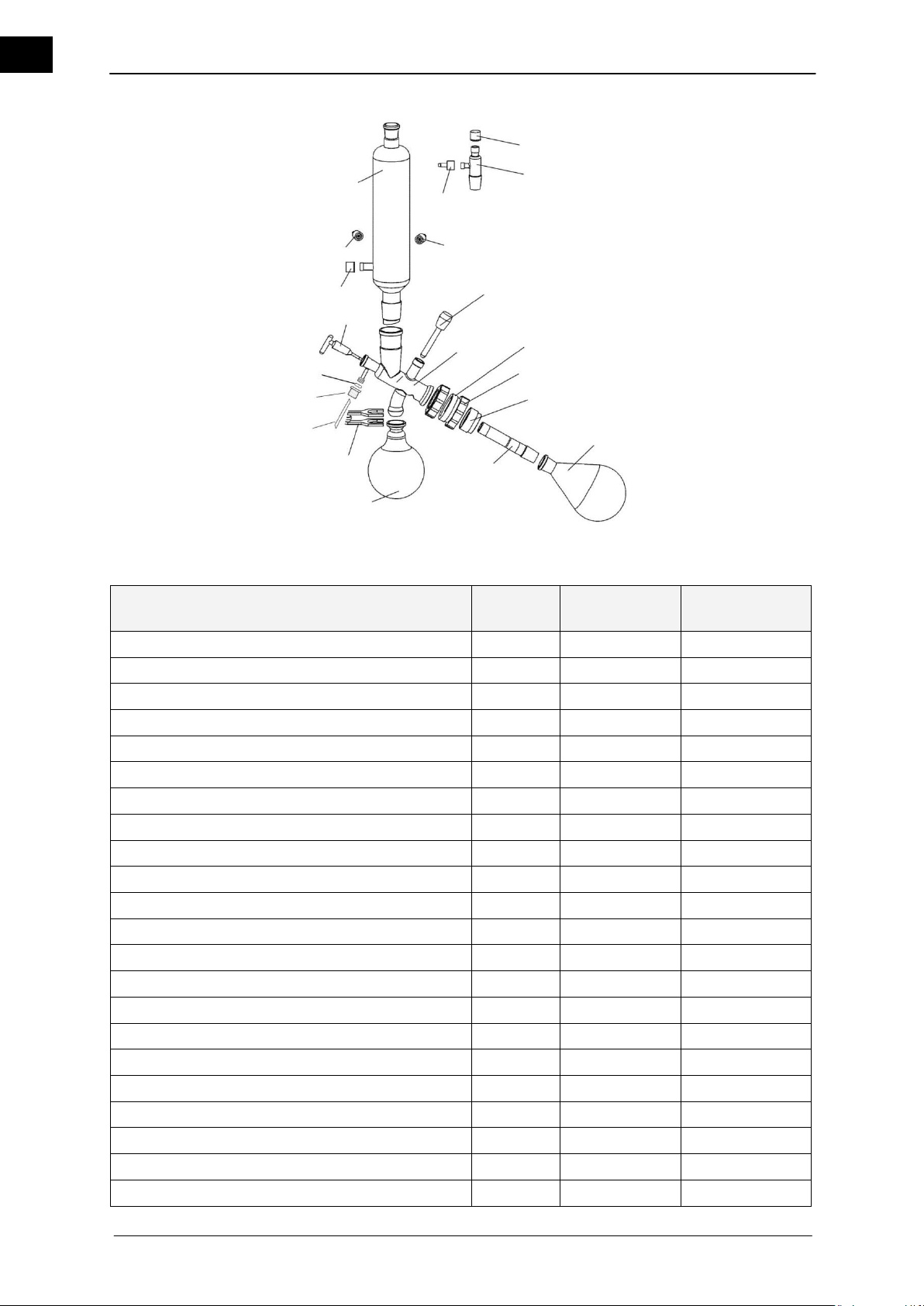
EN
Order description
Position
Order No.
Piece at delivery
Threaded fitting GL 18
1
23-09-03-01-24
2
Vacuum fitting NS 29 / 32
2
514-00001-00
1
Threaded fitting GL 14
3
23-09-03-01-27
3
Connector for the threaded fitting GL 14
3
11-300-005-22
3
Valve
4
514-48000-00
1
Center piece G6
5
514-00601-00
1
Center piece G6B, plastic coated
5
514-00611-00
(1)
G6 threaded coupling
6
515-62000-00
1
Gasket G6
7
23-30-01-01-35
1
Intermediate part G6
8
22-30-01-05-02
1
Evaporator flask 1,000 ml, NS 29/32
9
514-74000-00
1
Evaporator flask 1,000 ml, NS 24/40
9
514-74000-05
(1)
Vapor tube NS 29 / 32 G6
10
514-00000-05
1
Vapor tube NS 24 / 40 G6
10
514-00020-06
(1)
Receiving flask 1000 ml, S 35/20
11
514-84000-00
1
Receiving flask 1000 ml, S 35/20, plastic coated
11
514-84000-02
(1)
Condenser clamp S 35/20
12
515-42000-00
1
Inlet tube (PTFE-) 3.5/4.5x600
13
23-30-01-04-72
1
Threaded fitting GL10 red
14
23-30-01-04-69
1
Seal O-ring 3.2x2.5
15
23-08-06-03-26
1
Inlet pipe (stopcock)
16
514-51000-00
1
Condenser G6
17
514-23000-00
1
1 2 3 3 3 1 4 5 6 7 8 9 10
11
12
13
14
15
16
17
Figure 11–4: Glassware set G6
66 Hei-VAP Value, Hei-VAP Advantage
Page 75
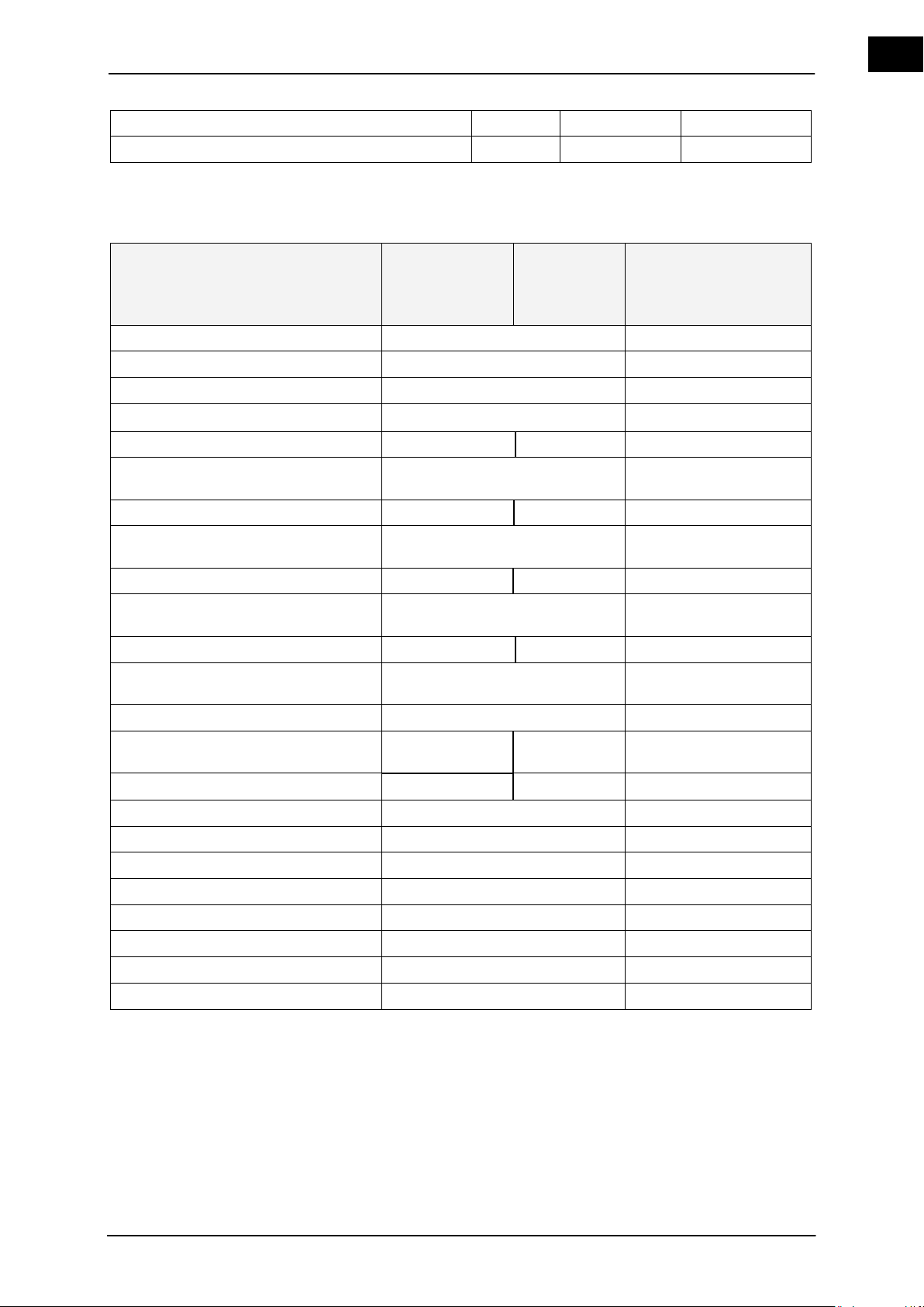
EN
Condenser G6B, plastic coated
17
514-23000-02
(1)
Condenser mounting
569-00050-00
1
Table 11-4: Glassware set G6
Order description
Order No.
230 V
50/60 Hz
Order No.
115 V
50/60 Hz
Comments
Protective hood
569-00010-00
Protective shield
569-00020-00
Vapor temperature sensor
569-00030-00
Temperature sensor Auto
accurate
sensor
569-00040-00
Vacuum pump ROTAVAC valve control
591-00130-00
591-00130-01
Condensate cooler for ROTAVAC valve
control
591-00081-00
Vacuum pump ROTAVAC valve tec
591-00160-00
591-00160-01
Condensate cooler for ROTAVAC valve
tec
591-00083-00
Vacuum pump ROTAVAC vario control
591-00141-00
591-00141-01
Condensate cooler for ROTAVAC vario
control
591-00084-00
Vacuum pump ROTAVAC vario tec
591-00171-00
591-00171-01
Condensate cooler for ROTAVAC vario
tec
591-00084-00
Vacuum box
569-00100-00
Vacuum controller VAC control automatic
569-00340-00
569-00340-01
Vacuum switch box for 3 consumers
569-00400-00
569-00400-01
Vacuum valve
569-00060-00
Woulff bottle
569-00070-00
Vacuum controller, manual
591-26000-00
Tube set
591-35000-00
Heating bath liquid (up to 180 °C)
515-31000-00
PTFE 26 Vacuum seal
23-30-01-01-30
Clamping sleeve
23-30-01-05-31
Transportation safety device
11-300-006-28
11.2 Accessories
Table 11-5: Accessories
Hei-VAP Value, Hei-VAP Advantage 67
Page 76
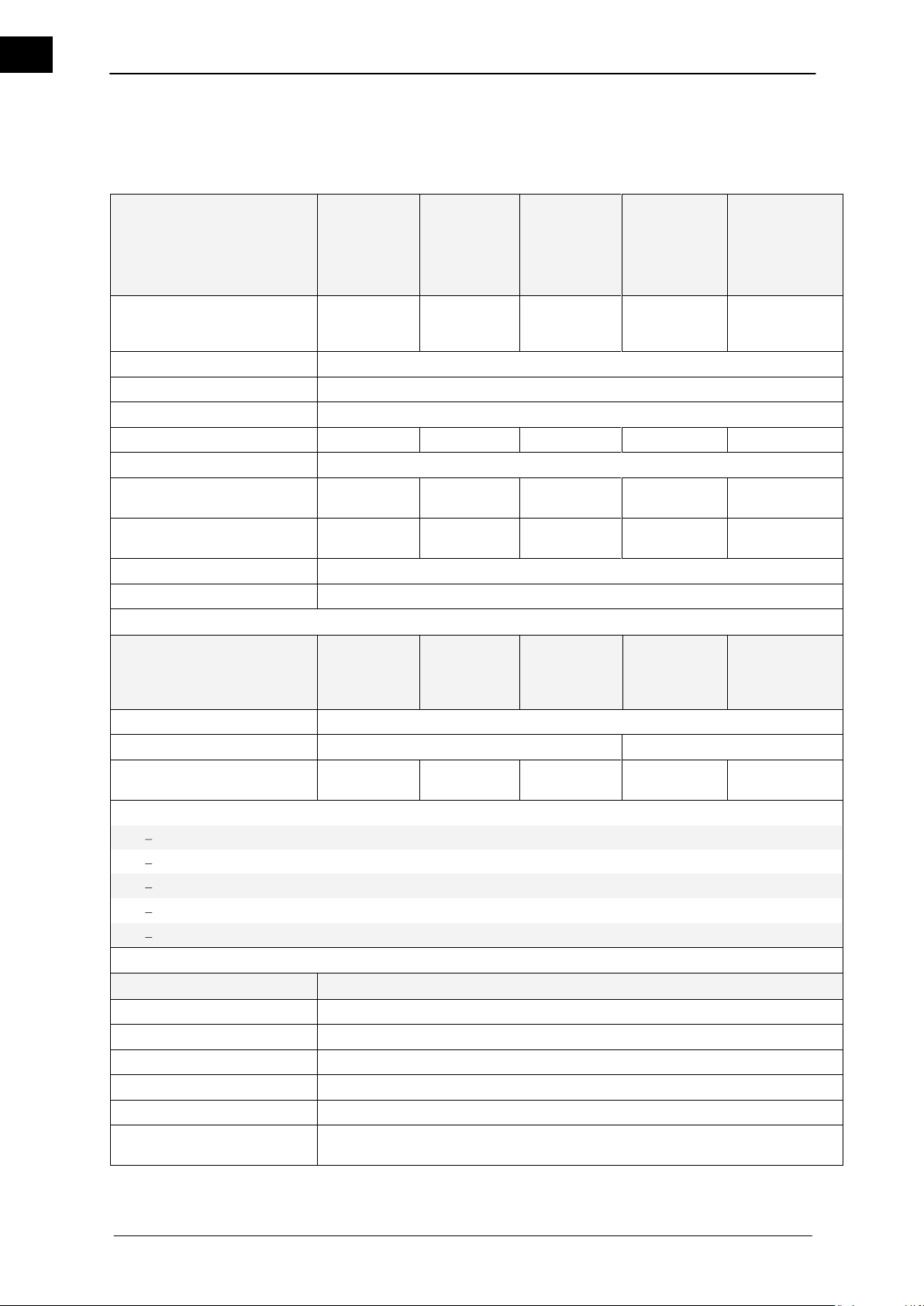
EN
Basic Device
Basis
Hei-VAP
Value
Basis
Hei-VAP
HL.
Basis
Hei-VAP
ML
Basis
Hei-VAP
HL
Basis
Hei-VAP
ML
Dimensions (WxDxH) of drive
unit in the lowest position without a glassware set ****
393 x 449 x
427 mm
393 x 449 x
427 mm
393 x 411 x
427 mm
393 x 449 x
427 mm
393 x 411 x 427
mm
Connected load
1400 W
Connected voltage
230 V / 50/60 Hz or 115 V / 50/60 Hz
Drive unit
EC motor with electronic speed control
Drive unit of lift
Manual
Manual
Motor
Manual
Motor
Speed range
10 – 280 min-1
Weight incl. heating bath
without glassware set
16 kg
16 kg
16 kg
17 kg
17 kg
Lifting speed
manual
manual
approx. 40
mm/s
manual
approx. 40
mm/s
Length of stroke
155 mm
Cooling surface
1,200 cm²
Panel
Bedienpanel
Value or
Bedienpanel
Collegiate
Bedienpanel
AdvantageHL
Bedienpanel
Advantage
ML
Bedienpanel
Precision HL
Bedienpanel
Precision ML
Connected load
24V dc
Connected voltage
1W
2W
display
Scale
3.5" LCD
screen
3.5" LCD
screen
4.3" LCD color
screen
4.3" LCD color
screen
Control panel
Lift
- - yes - yes
Start Rotation
yes
yes
yes
yes
yes
Start Vakuum
- - -
yes
yes
Start Heizbad
yes
yes
yes
yes
yes
Start Timer
-
yes
yes
yes
yes
Heating Bath
Heizbad Hei-VAP
Heating capacity
1300 W
Diameter of heating bath
255 mm
Heating bath material
V4A (1.4404)
Heating bath temperature range
20–210 °C
Heating bath control accuracy
±1 K
Heating bath temperature control
electronic/digital
12 Appendix
12.1 Technical data
68 Hei-VAP Value, Hei-VAP Advantage
Page 77
EN
Degree of protection
IP 20
Airborne sound level
Clearly lower than 85 db(A)
Permissible ambient conditions
5 – 31 °C at 80 % relative humidity
32 – 40 °C decreasing linear to a max. rel. humidity of 50%
0 - 2000m absolute altitude
Pollution Degree 2
Installation Category II
Connected voltage *** ±10%
230 V / 50/60
Hz
230 V / 50/60
Hz
230 V / 50/60
Hz
230 V / 50/60
Hz
230 V / 50/60
Hz
115 V / 50/60
Hz
115 V / 50/60
Hz
115 V / 50/60
Hz
115 V / 50/60
Hz
115 V / 50/60
Hz
Evaporation rate (L/h) ΔT*
20/40 °C
Toluene
4,1 / 8,2
4,1 / 8,2
4,1 / 8,2
4,1 / 8,2
4,1 / 8,2
Acetone
2,4 / 4,7
2,4 / 4,7
2,4 / 4,7
2,4 / 4,7
2,4 / 4,7
Ethanol
1,6 / 3,2
1,6 / 3,2
1,6 / 3,2
1,6 / 3,2
1,6 / 3,2
Water
0,5 / 1,0
0,5 / 1,0
0,5 / 1,0
0,5 / 1,0
0,5 / 1,0
Table 12-1: Technical data
* ΔT = Difference between the heating bath temperature and the boiling temperature
** Only possible in conjunction with vacuum systems
*** Standard 230 V/50/60 Hz: other connecting voltages upon request
**** Ready to connect including the power plug
Unit configuration
Hei-VAP Value:
With manual control valve for limiting the vacuum and a Rotavac valve vacuum pump
Manual vacuum controller for limiting the vacuum with the ROTAVAC valve control
Manual vacuum controller for limiting the vacuum with the ROTAVAC valve tec
Without a controller with a Rotavac valve vacuum pump
ROTAVAC valve control or ROTAVAC valve tec
With a controller and valve-controlled vacuum pump
Vac control automatic with vacuum valve (optional Woulff bottle) and ROTAVAC valve control
Vac control automatic with vacuum valve (optional Woulff bottle) and ROTAVAC valve tec
With controller and vacuum
Valve Control automatic with vacuum valve (optional Woulff bottle) and vacuum
With manual control valve and vacuum
Manual vacuum controller for limiting the vacuum with vacuum
Hei-VAP Advantage:
Without a controller with a Rotavac valve vacuum pump
ROTAVAC valve control or ROTAVAC valve tec
With a controller and valve-controlled vacuum pump
Vac control automatic with vacuum valve (optional Woulff bottle) and ROTAVAC valve control
Vac control automatic with vacuum valve (optional Woulff bottle) and ROTAVAC valve tec
With controller and vacuum
Valve Control automatic with vacuum valve (optional Woulff bottle) and vacuum
With vacuum
vacuum only
Hei-VAP Value, Hei-VAP Advantage 69
Page 78

EN
Order No.
569-00100-00
Connected voltage
24V DC
Connected load
3 W
Hei-VAP Precision:
Rotary evaporator Hei-VAP with valve-controlled vacuum pump
Vacuum valve (optional Woulff bottle) and ROTAVAC valve control
with vacuum valve (optional Woulff bottle) and ROTAVAC valve tec
Rotary evaporator Hei-VAP with speed-controlled vacuum pump
with ROTAVAC vario control
with ROTAVAC vario tec
Rotary evaporator Hei-VAP with vacuum
with vacuum valve (optional Woulff bottle) and vacuum
Expanded function of the above listed configurations
Function "Auto
Display of the vapor temperature with boiling temperature sensor
accurate
“ with Auto
accurate
sensor
12.2 Technical data o the vacuum box Hei-VAP
Table 12-2: Technical data o the vacuum box
70 Hei-VAP Value, Hei-VAP Advantage
Page 79
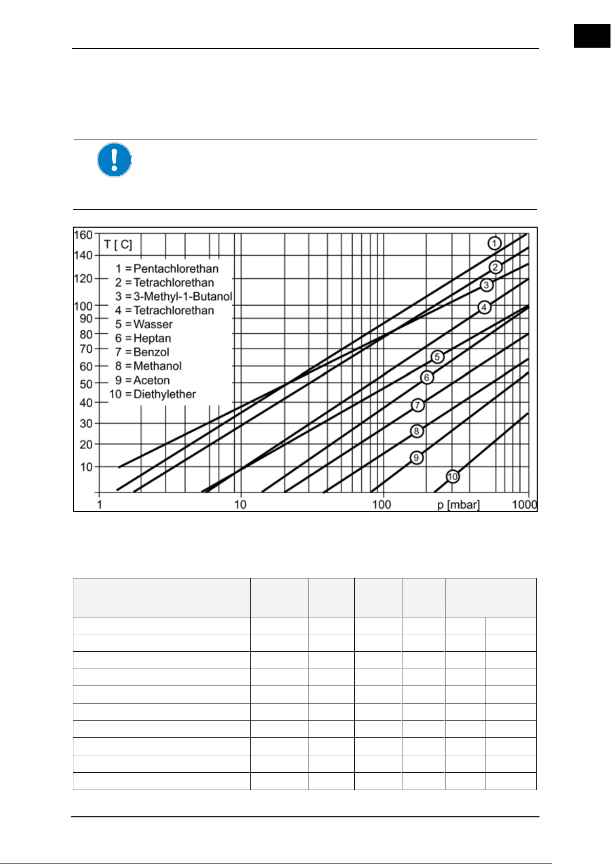
EN
12.3 Solvent data
The temperature difference between the vapor temperature and the cooling medium
should be at 20 K to result in sufficient condensation.
The temperature difference between the heating bath and vapor temperature should be at
20 K to result in a sufficient Distillation rate (dT).
i.e.: Set a vacuum for a boiling point at 40 °C, set the heating bath temperature at 60 °C.
Solvents
Total
formula
MW
[g/mol]
Boiling
point
[°C]
Δhvap
[J/g]
Vacuum for a
boiling point at
40 °C
[mbar]
[mm(Hg)]
Acetone
C3H6O
58,08
56,5
550
556
387
Acetonitrile
C2H3N
41,05
81,8
833
230
173
Benzene
C6H6
78,11
80,1
549
236
177
n-butanol (butyl alcohol)
C4H10O
74,12
117,5
619
25
19
tert.-butanol (tert-butyl alcohol)
C4H10O
74,12
82,9
588
130
98
2-Butanone (methyl ethyl ketone)
C4H8O
72,11
79,6
473
243
182
Chlorobenzene
C6H5CI
112,60
132,2
375
36
27
Cyclohexane
C6H12
84,16
80,7
389
235
176
1.2 Dichloroethane
C2H4CI2
98,96
82,4
336
210
158
The graph shows the relationship between the pressure and boiling temperature of a selection of solvents.
Figure 12–1: Graph
Torr to mbar conversion: [mmHg] ≈ 3/4 [mbar]
Solvent data
Hei-VAP Value, Hei-VAP Advantage 71
Page 80

EN
Solvents
Total
formula
MW
[g/mol]
Boiling
point
[°C]
Δhvap
[J/g]
Vacuum for a
boiling point at
40 °C
[mbar]
[mm(Hg)]
1,2 Dichloroethylene (cis)
C2H2CI2
96,94
59,0
320
479
134
1,2 Dichloroethylene (trans)
C2H2CI2
96,94
47,8
313
751
563
Dichloromethane (methylene chloride)
CH2CI2
84,93
40,7
373
atm.
atm.
Diethyl ether
C4H10O
74,12
34,6
392
atm.
atm.
Diisopropyl ether
C6H14O
102,20
67,5
318
375
281
Dimethylformamide
C3H7NO
73,09
153,0
11
8
1,4-Dioxane
C4H8O2
88,11
101,1
406
107
80
Ethanol
C2H6O
46,07
78,4
879
175
131
Ethylacetate
C4H8O2
88,11
77,1
394
240
180
Heptane
C7H16
85,09
98,4
439
120
90
Hexane
C6H14
86,18
68,7
370
335
251
Methanol
CH4O
32,04
64,7
1225
337
253
3-Methyl-1-butanol (Isoamyl alcohol)
C5H12O
88,15
130,6
593
14
11
Pentachlorinated Ethane
C2HCI5
202,30
160,5
203
13
10
Pentane
C5H12
72,15
36,1
382
atm.
atm.
n-Pentanol (amyl alcohol)
C5H12O
88,15
137,8
593
11
8
1-Propanol (n-propyl alcohol)
C3H8O
60,10
97,8
787
67
50
2-Propanol (isopropyl alcohol)
C3H8O
60,10
82,5
701
137
103
1,1,2,2-Tetrachloroethane
C2H2CI4
167,90
145,9
247
35
26
Tetrachloroethylene
C2CI4
165,80
120,8
233
53
40
Tetrachloromethane (carbon tetrachloride)
CCI4
153,80
76,7
225
271
203
Tetrahydrofuran (THF)
C4H8O
72,11
66,0
–
357
268
Toluene
C7H8
92,14
110,6
425
77
58
1,1,1-Trichloroethane
C2H3CI3
133,40
74,1
251
300
225
Trichloroethylene
C2HCI3
131,40
86,7
265
183
137
Trichloromethane (chloroform)
CHCI3
119,40
61,3
263
474
356
Water
H2O
18,02
100,0
2259
72
54
Xylene (isomers mixture)
C8H10
106,20
137–
143
390
25
19
Table 12-3: Solvent data
72 Hei-VAP Value, Hei-VAP Advantage
Page 81

EN
12.4 EC Declaration of Conformity
EN 61326-1:2006 + correction 2006
EN 61326-2-1:2006
EN 61326-2-2:2006
EN 61326-2-3:2006
EN 61326-2-4:2007
EN 61326-2-5:2007
EN 61326-2-6:2007
EN 61326-3-1:2008
EN 61326-3-2:2008
EN 61000-3-2:2006
EN 61000-3-3: 1995 + 2006 + A1:2001 + A2: 2005
EN 61000-4-2:1995 +A1:1998+A2:2001
EN 61000-4-3:2006 +A1:2008
EN 61000-4-4:2004
EN 61000-4-5:2006
EN 61000-4-6:2007 + corrigendum 2007
EN 61000-4-11:2004
EN 60529: 1991 + A1 : 2000
Date:
18.07.2009
Signature:
Name of the undersigned:
S. Richter
We, Heidolph Instruments GmbH & Co. KG,
Heidolph Instruments GmbH & Co. KG
Vertrieb Labortechnik
Walpersdorfer Str. 12
91126 Schwabach / Germany
declare that rotary evaporators of the Hei-VAP series for:
distillation, evaporation
purification of chemicals, substances, mixtures and preparations
processing reaction batches
drying of powder
Construction year: since 2009
Serial number: see model plate
Component number: see model plate
comply with the following standards and standardized documents:
EMV guideline 2004/108/EG:
Low Voltage Directive:
2006/95/EG
EN 61010-1:2001 + first correction: 2002 + second correction 2002
EN 61010-2-010:2003
Airborne noise emission:
EN ISO 3744:1995 and EN ISO 2151:2008
This declaration is void if modifications were performed on the unit without our prior consent.
The declaration of conformity was created according to DIN EN ISO/IEC 17050-1 "General criteria for supplier's
declaration of conformity".
Hei-VAP Value, Hei-VAP Advantage 73
Page 82

EN
Heidolph Instruments guarantees a warranty of three years for the products
described here (except glass and wear parts) if you are registering with the
enclosed warranty card or via the Internet (www.heidolph.com). The warranty
begins with the registration. The serial number of the unit is valid without the
registration. This warranty covers material and manufacturing defects. Transport damages are excluded.
In the event of a warranty claim, please contact Heidolph Instruments (Tel:
(+49) 9122 - 9920-69) or your local Heidolph Instruments dealer.
If it is a material or manufacturing defect, the unit will be repaired or replaced
free of charge within the scope of the warranty.
Heidolph Instruments will not assume any guarantees for damages due to
improper treatment.
Heidolph Instruments GmbH & Co. KG
Vertrieb Labortechnik
Walpersdorfer Str. 12
91126 Schwabach / Germany
12.5 Warranty Statement
74 Hei-VAP Value, Hei-VAP Advantage
Page 83

EN
12.6 Declaration of non-objection
1. Information regarding the
unit
Model description
Part number
Reason for submission
2. Was the device cleaned, if
necessary, decontaminated
/ disinfected?
Yes
No
3. Is the unit in a condition
that poses no health risks
to repair personnel?
Yes
No
If no, what substances was the unit
in contact?
4. Information regarding the
sender
Last name, first name
Company
Department
Street
Postal code / city
Country
Telephone
E-mail
5. Legally binding declaration
The client is aware that he is liable
to the contractor for damages
caused by incomplete and incorrect
information.
Date
Signature
Copy and mail / fax this declaration in the event of repairs to Heidolph Instruments GmbH & Co KG (see Chapter
9.4).
Hei-VAP Value, Hei-VAP Advantage 75
Page 84

01-005-004-79 24.08.2009
© Heidolph Instruments GmbH & Co. KG
Technische Änderungen sind ohne vorherige Ankündigung vorbehalten.
Technical changes reserved. Publication not mandatory.
Sous réserve de modifications techniques sans notification préalable.
Nos reservamos el dechero de introducir modificaciones técnicas sin previo aviso.
Ci si riserva il diritto di apportare modifiche tecniche senza preavviso.
 Loading...