

Page 1

Nexscan F 4100/F 4200
Operation
Edition September 2000
Order No. 05573483
ABC
Page 2

I
mprint/Company
Add
ress
Copyright © 2001 Heidelberger
Druckmaschinen Aktiengesellschaft.
No part of this book may be reproduced without prior written permission.
. . . . . . . . . . . . . . . . . . . . . . . . . . . . . . . . . . . . . . . . . . . . . . . . . . . . . . . . . . . . . . . . . . . . . . . . . . . . .
Agfa® is a registered trademark of
Bayer Corporation and its subsidiary
companies.
®
Newcolor
and Nexscan
trademarks of Heidelberger
Druckmaschinen AG.
Kodak
, Newcopix®, LinoColor®
®
are registered
®
is a registered trademark of
Eastman Kodak Company.
®
Apple
, the Apple Logo®, AppleTalk®,
®
ColorSync
. . . . . . . . . . . . . . . . . . . . . . . . . . . . . . . . . . . . . . . . . . . . . . . . . . . . . . . . . . . . . . . . . . . . . . . . . . . . . . . . . . .
, EtherTalk®, LaserWriter®,
Heidelberger Druckmaschinen AG
Dr.-Hell-Straße
D-24107 Kiel
Phone +49 (4 31) 3 86-0
Fax +49 (4 31) 3 86-1380
http://www.heidelberg.com/
®
Macintosh
are registered trademarks of Apple
and Power Macintosh®
Computer, Inc.
Other company names, product
names and trademarks not expressly
mentioned in this manual are
trademarks or registered trademarks
of the corresponding manufacturers
and fall within the regulations
regarding the protection of
trademarks.
Important notice:
We are dedicated to improving and
enhancing our products. For this
reason, we reserve the right to make
changes without notice.
Heidelberger Druckmaschinen AG
assumes no responsibility for
information and description as far as
third-party products are concerned.
The information contained in this
manual about performance and
concerning application of our
products is not legally binding as it
does not constitute a written
contract of features.
If any problems occur with the
product described in this manual,
please contact the Heidelb erg agency
which is responsible for you.
Order No. 05573483
Edition September 2000
speed as well as technical data
Page 3

ABC
Table of Contents
Table of Contents
Before you start ...
Notes on Technical Safety . . . . . . . . . . . . . . . . . . . . VII
Designated Use . . . . . . . . . . . . . . . . . . . . . . . . . . . . . VII
General . . . . . . . . . . . . . . . . . . . . . . . . . . . . . . . . . . . . VII
Prerequisites . . . . . . . . . . . . . . . . . . . . . . . . . . . . . . . VIII
Other Documentation . . . . . . . . . . . . . . . . . . . . . . . . VIII
About This Documentation . . . . . . . . . . . . . . . . . . . . IX
Conventions Used in This Manual . . . . . . . . . . . . . . . . IX
Important Information . . . . . . . . . . . . . . . . . . . . . . . . . . X
Influence of Magnetic Fields on the Monitors . . . . . X
Any Comments on this Documentation? . . . . . . . . . XI
HEIDELBERG Online . . . . . . . . . . . . . . . . . . . . . . . . XII
1 Unpacking and Installing
Dear Customer . . . . . . . . . . . . . . . . . . . . . . . . . . . . . 1–1
Power connection . . . . . . . . . . . . . . . . . . . . . . . . . . . 1–1
Scope of Delivery . . . . . . . . . . . . . . . . . . . . . . . . . . . 1–1
Unpacking and Installing . . . . . . . . . . . . . . . . . . . . . 1–2
2 Connecting
Installation . . . . . . . . . . . . . . . . . . . . . . . . . . . . . . . . . 2–1
Connecting the Nexscan F 4100/F 4200 to the
workstation . . . . . . . . . . . . . . . . . . . . . . . . . . . . . . . . . 2–1
Connecting the Nexscan F 4100/F 4200 to the power
supply . . . . . . . . . . . . . . . . . . . . . . . . . . . . . . . . . . . . . 2–3
Switching on the Nexscan F 4100/F 4200 . . . . . . . . . 2–6
Installing the Newcolor Software . . . . . . . . . . . . . . . . . 2–6
Installing the LinoColor Software . . . . . . . . . . . . . . . . 2–6
Installing Calibration Data . . . . . . . . . . . . . . . . . . . . . . 2–7
3 Product Description
General view Nexscan F 4100/F 4200 . . . . . . . . . . . 3–1
Product and Performance Features of the
Nexscan F 4100/F 4200 . . . . . . . . . . . . . . . . . . . . . . . 3–2
Overall configuration . . . . . . . . . . . . . . . . . . . . . . . . 3–4
Nexscan F 4100/F 4200 – Operation I
Page 4

Table of Contents
ABC
Scanning principle . . . . . . . . . . . . . . . . . . . . . . . . . . 3–5
Power Switch . . . . . . . . . . . . . . . . . . . . . . . . . . . . . . 3–7
Pilot Lamp . . . . . . . . . . . . . . . . . . . . . . . . . . . . . . . . . 3–7
Scanning Progress Indicator . . . . . . . . . . . . . . . . . 3–8
Universal tray . . . . . . . . . . . . . . . . . . . . . . . . . . . . . . 3–8
Mounting Rail . . . . . . . . . . . . . . . . . . . . . . . . . . . . . . 3–9
Scanning Area . . . . . . . . . . . . . . . . . . . . . . . . . . . . . 3–9
Screens . . . . . . . . . . . . . . . . . . . . . . . . . . . . . . . . . . . 3–9
Scales . . . . . . . . . . . . . . . . . . . . . . . . . . . . . . . . . . . . 3–9
Scanning Speed . . . . . . . . . . . . . . . . . . . . . . . . . . . 3–10
Illumination of originals . . . . . . . . . . . . . . . . . . . . . 3–10
4 Working with the Nexscan F 4100/F 4200
Operating Sequence . . . . . . . . . . . . . . . . . . . . . . . . 4–1
Preparation for Production . . . . . . . . . . . . . . . . . . . . . 4–1
Preparing the Tray . . . . . . . . . . . . . . . . . . . . . . . . . . . 4–2
Positioning the Originals . . . . . . . . . . . . . . . . . . . . . . . 4–2
On the Glass Plate in the Device . . . . . . . . . . . . . . 4–2
On the Universal Tray . . . . . . . . . . . . . . . . . . . . . . . 4–3
Securing the Originals . . . . . . . . . . . . . . . . . . . . . . . . 4–4
Inserting the Tray . . . . . . . . . . . . . . . . . . . . . . . . . . . . 4–4
Close Scanner Lid . . . . . . . . . . . . . . . . . . . . . . . . . . . 4–5
Scanning Process . . . . . . . . . . . . . . . . . . . . . . . . . . 4–6
Scanning Three-Dimensional Objects . . . . . . . . . . 4–8
Placing Objects . . . . . . . . . . . . . . . . . . . . . . . . . . . . . 4–8
Selecting Reflection Scanning Mode . . . . . . . . . . . . . 4–8
Selecting the Quality . . . . . . . . . . . . . . . . . . . . . . . . . 4–9
Mounting with Oil, Film Cleaner or Gel . . . . . . . . . 4–9
Mounting Procedure . . . . . . . . . . . . . . . . . . . . . . . 4–10
Mounting Selection . . . . . . . . . . . . . . . . . . . . . . . . 4–12
Light optimization . . . . . . . . . . . . . . . . . . . . . . . . . 4–14
Special scanner functions . . . . . . . . . . . . . . . . . . . 4–15
Reloading the Scanner Software (for Newcolor) . . . 4–15
Performing a Basic Level Adjustment (for Newcolor) 4–17
II Edition September 2000
Page 5

ABC
Table of Contents
Performing a Basic Level Adjustment (for Linocolor) 4–19
Resetting the Scanner (for Linocolor) . . . . . . . . . . . . 4–21
Updating the Scanner (for Linocolor) . . . . . . . . . . . . 4–23
Working with the Slide Tray . . . . . . . . . . . . . . . . . . 4–25
5 Accessories
Passepartouts . . . . . . . . . . . . . . . . . . . . . . . . . . . . . . 5–1
Slide Tray . . . . . . . . . . . . . . . . . . . . . . . . . . . . . . . . . . 5–2
Register Pin Row . . . . . . . . . . . . . . . . . . . . . . . . . . . 5–2
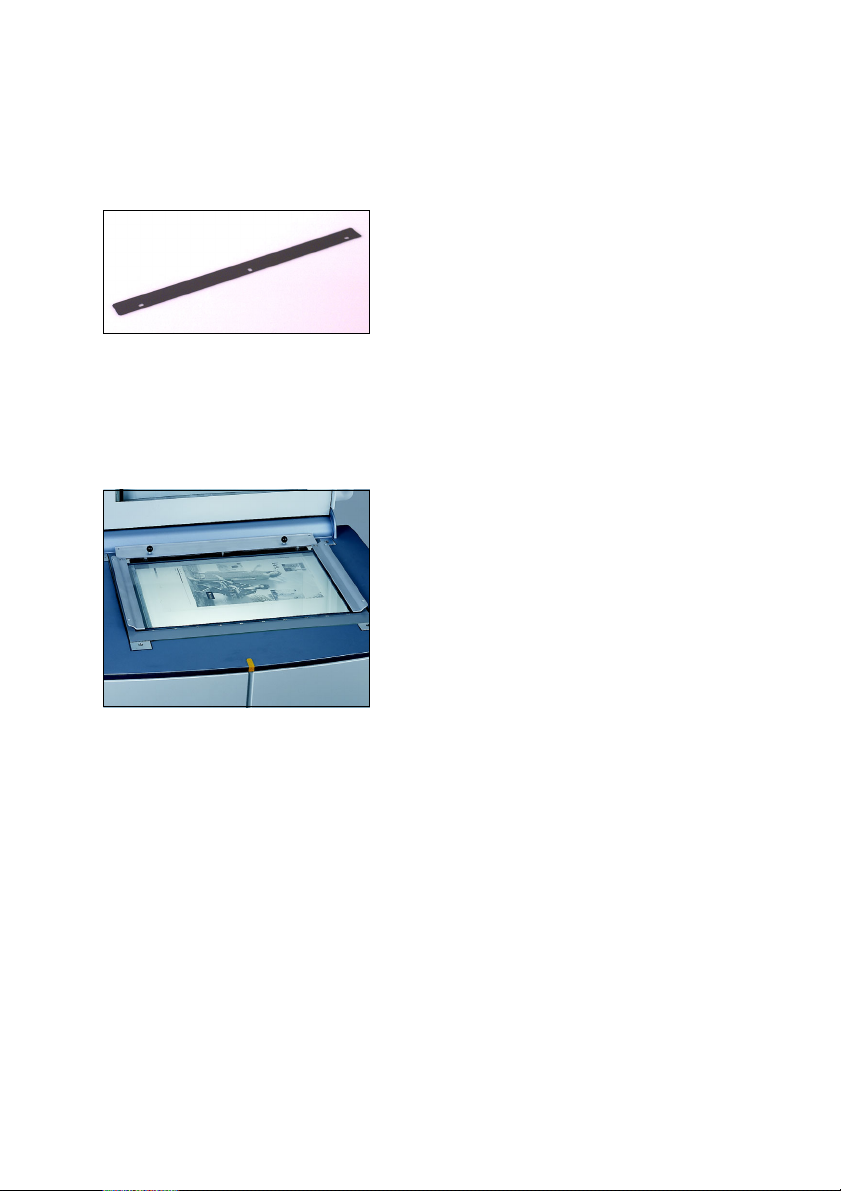
Register Strip . . . . . . . . . . . . . . . . . . . . . . . . . . . . . . 5–3
Copix Tray . . . . . . . . . . . . . . . . . . . . . . . . . . . . . . . . . 5–3
6 Service and Maintenance
Notes on Care and Maintenance . . . . . . . . . . . . . . . 6–1
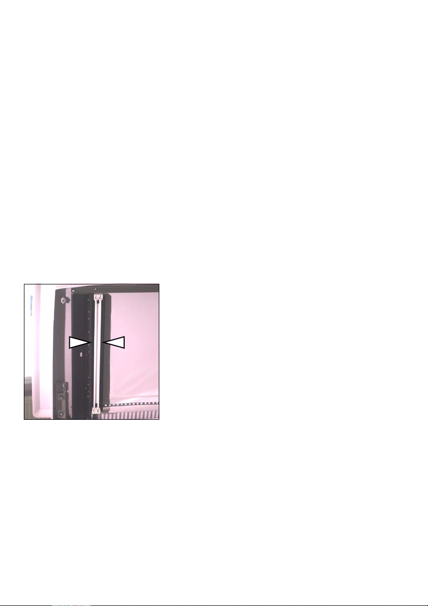
Fluorescent Lamps . . . . . . . . . . . . . . . . . . . . . . . . . . 6–2
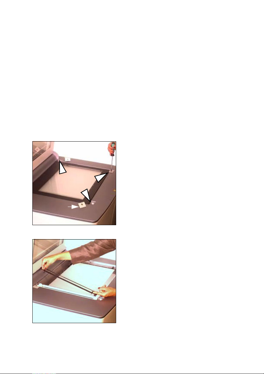
Lamp Change for Reflection Scanning . . . . . . . . . . 6–3
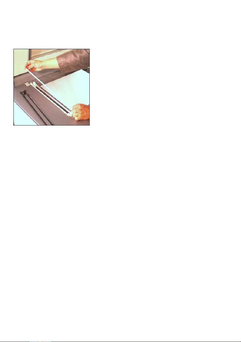
Lamp Change for Transparency Scanning . . . . . . . 6–5
Lamp Change for the Illumination of Originals . . . 6–7
Replacing the Glass Plate . . . . . . . . . . . . . . . . . . . . 6–8
Cleaning the Nexscan F 4100/F 4200 . . . . . . . . . . . 6–9
Removing Dust in the Lid . . . . . . . . . . . . . . . . . . . . 6–10
Cleaning the Glass Surface/Universal Tray . . . . . 6–11
Checking the Cleanliness of the Tray . . . . . . . . . . . . 6–11
Cleaning Preparation . . . . . . . . . . . . . . . . . . . . . . . . 6–11
Liquids . . . . . . . . . . . . . . . . . . . . . . . . . . . . . . . . . . . . 6–13
Dry Finger Prints; Adhesive Tape Residue, Smudges
(Except for Acetone Rings, Refer to Cleaning with
Acetone). . . . . . . . . . . . . . . . . . . . . . . . . . . . . . . . . . . 6–14
Streaks, Damp Areas, Fresh Finger Prints . . . . . . . . 6–15
Dust (To Be Removed Directly Before Scanning) . . . 6–15
Stains That Could Not Be Removed Following The
Previous Procedures . . . . . . . . . . . . . . . . . . . . . . . . . 6–16
Cleaning Originals . . . . . . . . . . . . . . . . . . . . . . . . . 6–17
Checking the Cleanliness of the Original . . . . . . . . . 6–17
Nexscan F 4100/F 4200 – Operation III
Page 6

Table of Contents
ABC
Preparing the Originals for Cleaning . . . . . . . . . . . . 6–17
Liquids . . . . . . . . . . . . . . . . . . . . . . . . . . . . . . . . . . . 6–19
Dry Finger Prints; Adhesive Tape Residue,
Dry Smudges . . . . . . . . . . . . . . . . . . . . . . . . . . . . . . 6–19
Dust . . . . . . . . . . . . . . . . . . . . . . . . . . . . . . . . . . . . . 6–20
Stains That Could Not Be Removed By Dabbing And
Cleaning With Ethanol . . . . . . . . . . . . . . . . . . . . . . . 6–21
Dust That Could Not Be Removed Following The
Normal Procedure . . . . . . . . . . . . . . . . . . . . . . . . . . 6–21
General Remarks on Maintenance . . . . . . . . . . . . 6–22
7 Technical Data and Accessories
Technical Data . . . . . . . . . . . . . . . . . . . . . . . . . . . . . 7–1
Accessories . . . . . . . . . . . . . . . . . . . . . . . . . . . . . . . 7–2
Consumables . . . . . . . . . . . . . . . . . . . . . . . . . . . . . . 7–3
Minimum Configuration for the PC . . . . . . . . . . . . . 7–4
Minimum Configuration for the Power Macintosh 7–4
Scanner System . . . . . . . . . . . . . . . . . . . . . . . . . . . . 7–5
Scanner Signal Resolutions . . . . . . . . . . . . . . . . . . 7–5
Type of Original . . . . . . . . . . . . . . . . . . . . . . . . . . . . 7–5
Power connection . . . . . . . . . . . . . . . . . . . . . . . . . . 7–6
Fuses . . . . . . . . . . . . . . . . . . . . . . . . . . . . . . . . . . . . . 7–6
Light Conditions . . . . . . . . . . . . . . . . . . . . . . . . . . . . 7–6
Device Emissions . . . . . . . . . . . . . . . . . . . . . . . . . . . 7–6
Standards . . . . . . . . . . . . . . . . . . . . . . . . . . . . . . . . . 7–7
General . . . . . . . . . . . . . . . . . . . . . . . . . . . . . . . . . . . . 7–7
Mechanical Safety . . . . . . . . . . . . . . . . . . . . . . . . . . . 7–7
Electrical Safety . . . . . . . . . . . . . . . . . . . . . . . . . . . . . 7–7
Electromagnetic compatibility (EMC) . . . . . . . . . . . 7–7
Emission of Noise
(Radio Interference and Noise Voltage) . . . . . . . . . . . 7–7
Interference Immunity . . . . . . . . . . . . . . . . . . . . . . . . . 7–8
Radio Interference Suppression . . . . . . . . . . . . . . . . . 7–8
Approvals . . . . . . . . . . . . . . . . . . . . . . . . . . . . . . . . . . 7–8
IV Edition September 2000
Page 7

ABC
Table of Contents
Disposal of the Device . . . . . . . . . . . . . . . . . . . . . . . 7–9
Pollutants . . . . . . . . . . . . . . . . . . . . . . . . . . . . . . . . . . 7–9
Materials . . . . . . . . . . . . . . . . . . . . . . . . . . . . . . . . . . 7–10
Dismantling . . . . . . . . . . . . . . . . . . . . . . . . . . . . . . . . 7–11
Pollutants . . . . . . . . . . . . . . . . . . . . . . . . . . . . . . . . . 7–13
Materials/Plastics . . . . . . . . . . . . . . . . . . . . . . . . . . 7–14
Dismantling 1 . . . . . . . . . . . . . . . . . . . . . . . . . . . . . 7–15
Dismantling 2 . . . . . . . . . . . . . . . . . . . . . . . . . . . . . 7–16
Dismantling 3 . . . . . . . . . . . . . . . . . . . . . . . . . . . . . 7–17
EU Declaration of Conformity
Safety Labels
8 Quality Assurance
Quality Assurance . . . . . . . . . . . . . . . . . . . . . . . . . . 8–1
“Central Call Desk“ . . . . . . . . . . . . . . . . . . . . . . . . . . . 8–1
Problem Report for Customers and Service
Technicians . . . . . . . . . . . . . . . . . . . . . . . . . . . . . . . . . 8–1
Index
Nexscan F 4100/F 4200 – Operation V
Page 8

Page 9

ABC
Before you start ...
Notes on Technical Safety
The device corresponds to the safety regulations
listed in Standards, in the Technical Data and
Accessories chapter.
Designated Use
The Nexscan F 4100/F 4200 is a flatbed scanner
and should only be used for this purpose in
accordance with the Operating Instructions. Do
not place any objects or liquids on the unit.
The ventilation outlets must be kept clear at all
times.
General
Environmental conditions must be observed when
setting up the Nexscan F 4100/F 4200.
Before you start ...
Warning: Unauthorized opening of the unit's
housing and improper repairs not expressly
3
Nexscan F 4100/F 4200 – Operation VII
described in the operating instructions can lead to
considerable danger for the user.
Servicing work may only be performed by
authorized specialist personnel. The respective
accident prevention regulations must be observed
at all times.
Non-observance of accident prevention
regulations can lead to the loss of accident
insurance cover.
Page 10

Before you start ...
Prerequisites
ABC
We assume that you are familiar with the basic
functions of Windows NT
Macintosh
Other Documentation
You will find further information in the following
documentation:
For Newcolor/Newcopix:
For Linocolor:
®
®
.
0
Printed documentation:
and/or Apple®
- Newcolor Workflow
- Newcolor Installation
- Newcopix User's Guide/Reference
- Newcopix Installation
0
Online Helps (Reference)
0
Printed documentation:
- Linocolor Installation
- Linocolor Introduction (incl. Color Images)
- Linocolor User's Guide
- Nexscan F 4100/F 4200 Copix Operation
0
After installing LinoColor, you will find further
documentation in the documentation folder on
your computer, such as:
- Linocolor Reference
- GeoAssistant Application
(only available with GeoAssistant)
- JobAssistant User's Guide
0
LinoColor Help
0
JobAssistant Help
VIII Edition September 2000
Page 11

ABC
About This Documentation
This documentation should be kept safely for
future use until the device is disposed of.
Conventions Used in This Manual
The following typographical conventions are used
in this manual:
0
References to other manuals, chapters and
sections are colored in blue
are underlined
Example:
See Abschnitt
Manual.
0
Italics are used to indicate menus, names of
functions, hardware conditions, switch
settings, and system messages.
Example:
Move the switch to off.
0
Menus, functions and sub-functions are
separated with by ">".
Before you start ...
(on the screen) and
.
Conventions Used in This
Example:
Choose File > Open...
0
A plus sign is used to indicate that several keys
have to be pressed at the same time.
Example:
Press Alt+A.
0
“V" in front of a word denotes that you will find
further explanations of this word in the
glossary.
Nexscan F 4100/F 4200 – Operation IX
Page 12

Before you start ...
Important Information
Important information in the text is marked by
symbols which indicate the following:
Warning: Contains information that must be taken
into consideration to protect the user from injury.
3
Attention: Contains information that must be
taken into consideration to prevent damage to
1
Influence of Magnetic Fields on the Monitors
hardware or software.
Note: Contains important general or
supplementary information about a specific topic.
2
Prerequisites: This text contains requirements
which must be fulfilled before the steps which
5
follow can be performed.
Strong magnetic fields may influence your
monitor screen (for example, they might make the
edges of the screen unsteady or images flicker).
This could be caused by the 50 Hz magnetic field
coming from the power cables routed along your
floors or in the wall.
ABC
The following corrective measures are
recommended taking into account the safety
regulations for working at monitors in offices:
0
place the monitor at a different location
0
shield the source (e.g. shield the cable duct)
0
change the routing of the power supply cable
0
shield the monitor by means of a metal cover
X Edition September 2000
Page 13

ABC
Any Comments on this Documentation?
We would like to know if our documentation
meets your requirements.
0
Can you find the information you are looking
for? (and quickly enough?)
0
Does this documentation help you to solve any
problems which might occur?
0
Where do you think there is room for
improvement? ...
If you would like to make some comments on the
documentation, please feel free to send these to us
at the following e-mail address:
Before you start ...
It would help us if you could write your comments
in English or German.
Important!
Please do not use this e-mail address for
improvement suggestions for the product Nexscan
F 4100/F 4200, only for tips, corrections, criticism
and suggestions with regard to the relevant
documentation. If you have comments which you
would like to make on the improvement or
enhancement of our products, please forward
these to us using the Problem Report for Customers
and Service Technicians.
To order documentation, please contact the
Heidelberg agency which is responsible for you.
Nexscan F 4100/F 4200 – Operation XI
Page 14

Before you start ...
HEIDELBERG Online
Do you have questions concerning our products?
Do you want to improve your workflows?
Pay us a visit at our Internet home page. You will
find us at:
ABC
http://www.heidelberg.com/
XII Edition September 2000
Page 15

ABC
1 Unpacking and Installing
Dear Customer
With the Nexscan F 4100/F 4200 you have
purchased a high-quality and fast CCD color line
scanner.
To make sure that you are always completely
satisfied with the performance of the device,
please observe the following unpacking and
installation instructions, once you have removed
the cardboard box or foil.
Power connection
Read the chapter on unpacking and installing before you connect the device to the power source.
Scope of Delivery
The scope of delivery for your Nexscan F 4100/
F 4200 comprises the following parts:
0
0
0
0
0
0
0
0
0
0
0
Unpacking and Installing
1 SCSI cable
3 Power cable
1Calibration CD
1 Universal tray
1 Mounting rail
1 Flat screwdriver
1 Documentation
1 Base aperture
2 Fluorescent tubes
1 Passepartout – basic set
1 Slide tray
Nexscan F 4100/F 4200 – Operation 1– 1
Page 16
Unpacking and Installing
Unpacking and Installing
When setting up the Nexscan F 4100/F 4200, the
notes in both this chapter and in chapter 2 in
these Operating Instructions must be observed.
Note: Do not install the device in the vicinity of airconditioning systems and protect it from moisture
2
and direct sunlight.
So far you have proceeded according to the
unpacking instructions stuck to the outside of the
box. You have taken this documentation out of the
accessories box.
Further unpacking and installation procedure:
ABC
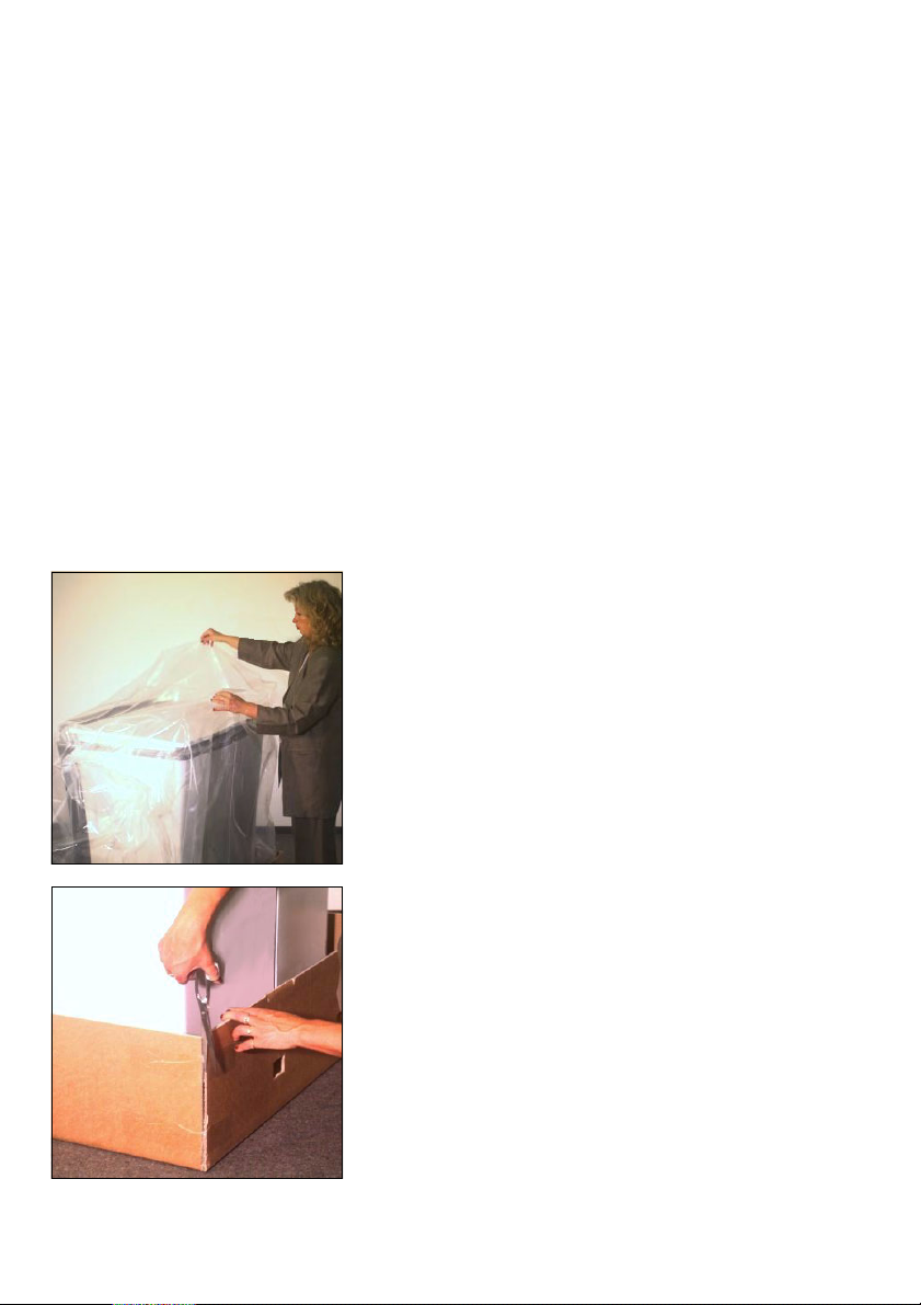
1. Removing the plastic foil
Remove the plastic foil that surrounds
the scanner.
2. Cutting open the box
Cut open the four lower corners of the
cardboard box.
1– 2 Edition September 2000
Page 17
ABC
Unpacking and Installing
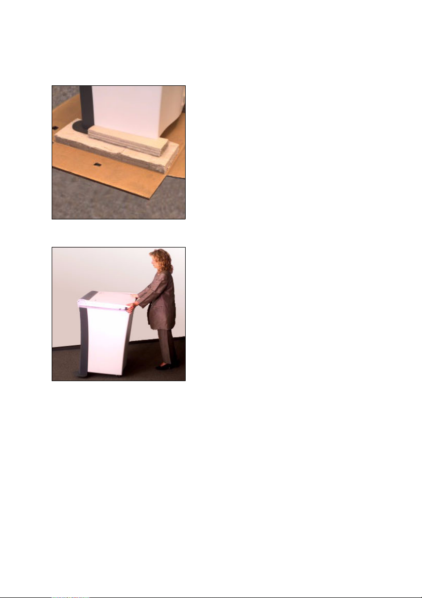
3. Removing parts of the box
Remove all cardboard box parts under
the scanner. A second person is required to slightly raise the scanner for this
purpose.
4. Pushing the scanner to the installation
site
Push or pull the scanner to the site
where it will be taken into operation.
However, allow approx. 1 m gap to the
wall as cables still need to be connected
later and the back panel must be screwed on and off.
Nexscan F 4100/F 4200 – Operation 1– 3
Page 18
Unpacking and Installing
Note: Take the length of the SCSI cable
between scanner and computer into
2
account when positioning the scanner.
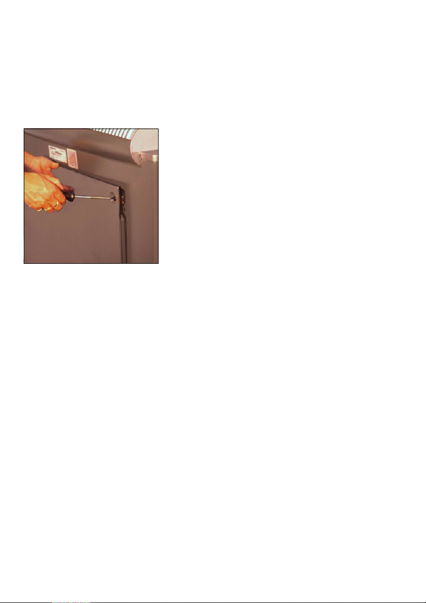
5. Removing the back panel
Unscrew the four screws at the back of
the device with a flat screwdriver and
remove the back panel.
You will need the CD with the ICC profiles, which is attached to the back panel,
later on when installing the software.
Attention: When loosening transport
1
safety devices: Work carefully!
0
Ensure that you do not support yourself on the fluorescent tubes in the bottom of the device and that no parts fall
onto the fluorescent tubes.
0
Do not touch the stray light foil above
in the scanner.
ABC
Note: All transport safety devices to be
removed are identified with a red mar-
2
king (adhesive label).
1– 4 Edition September 2000
Page 19
ABC
Unpacking and Installing
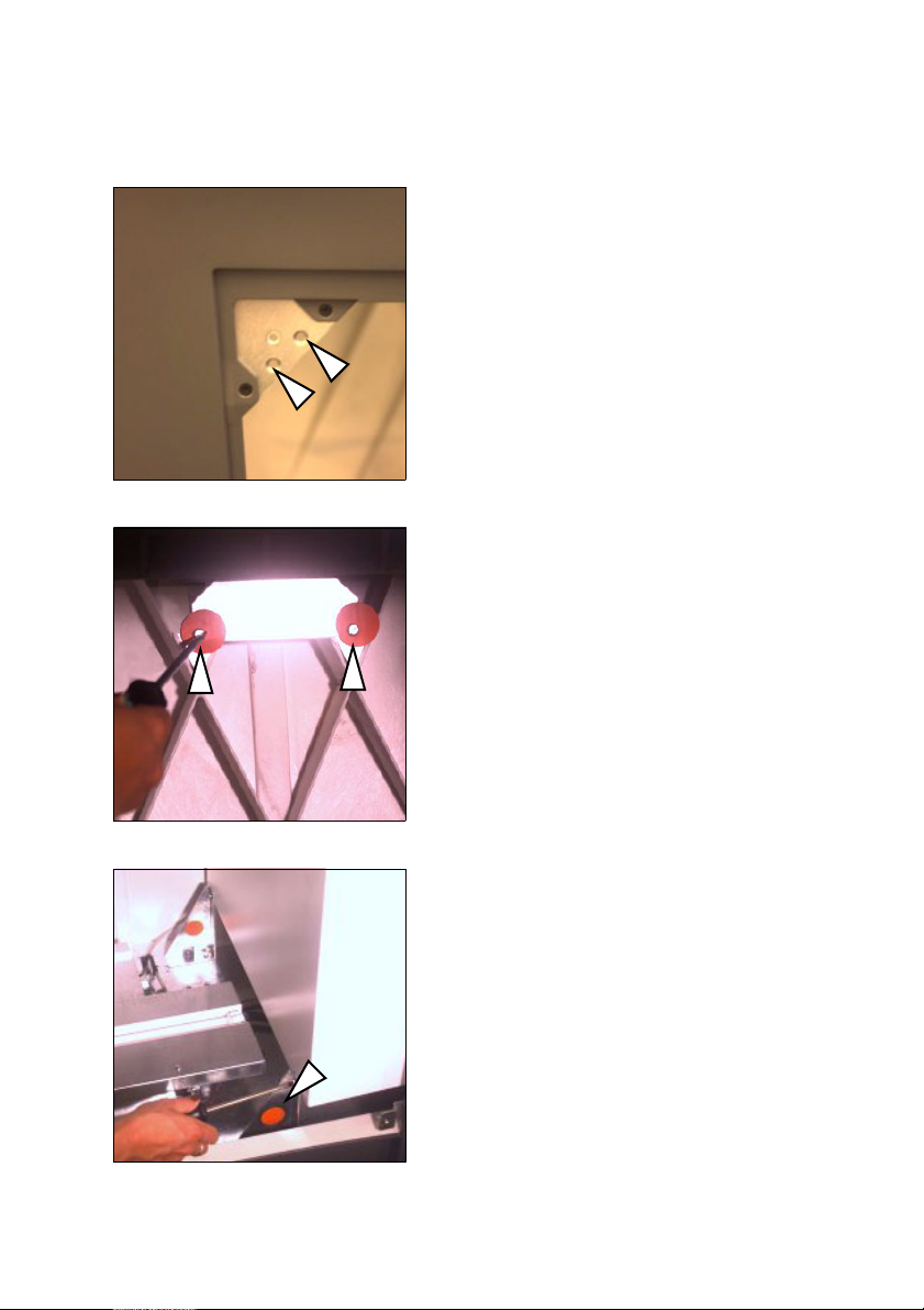
6. At the rear in the device, use a flat
screwdriver to remove the 2 vertical
slotted screws (not the double seams
screws!) to the upper left in the back
panel cutout.
7. Remove the 2 screws at the front, inside
the device, connecting the device housing and the scanning unit (accessible
from the rear only).
8. Removing the shipping restraint brakket
Unscrew the three screws on the shipping restraint at the back of the device
and remove it.
Nexscan F 4100/F 4200 – Operation 1– 5
Page 20
Unpacking and Installing
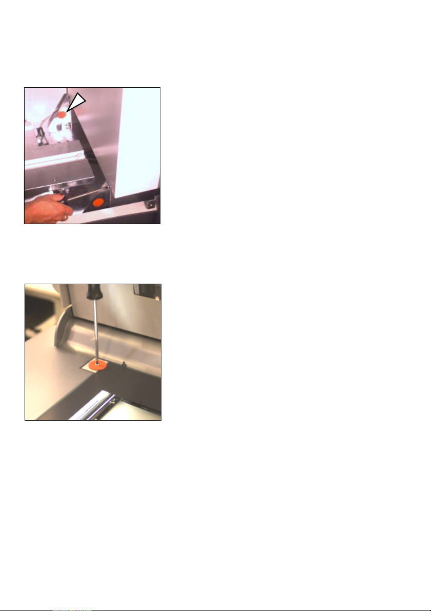
ABC
9. Removing the shipping restraint brakket
A similar safeguard must now be removed at the front of the device. The three
screws must be unscrewed in the same
fashion.
10. Open the scanner lid
11. Remove the air-cushion foil and the silk
paper
12. Removing the transport safety washer
Remove the slotted screw with a flat
screwdriver and remove the transport
safety washer.
Replace the screw and use it to secure
the clamp.
1– 6 Edition September 2000
Page 21
ABC
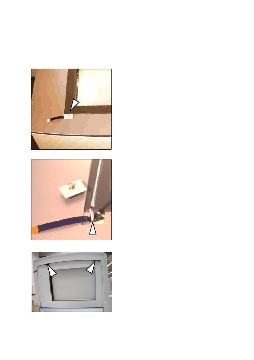
Unpacking and Installing
13. Unscrewing the shipping restraint
screw
0
Unscrew the screw on the clamp element for the front left glass plate with
a flat screwdriver. Remove the clamp
element.
0
Unscrew and remove the now visible
screw.
0
Replace the clamp element and fasten
it with the screw. Ensure that you
have inserted the clamp element the
right way round so that the glass pane
does not break.
14. Removing the clamping pads
Remove the two clamping pads for the
knurled screws.
Nexscan F 4100/F 4200 – Operation 1– 7
Page 22
Unpacking and Installing
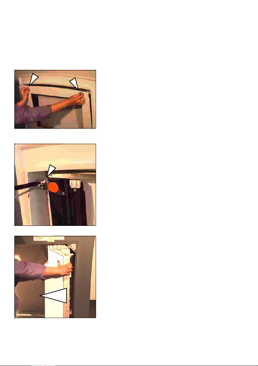
ABC
15. Removing the bracket for transparency
scanning
0
Remove the two knurled screws in the
scanner lid and carefully remove the
plate with the glass pane.
0
Remove the bracket for the transparency scanning by unscrewing the
screw with a flat screwdriver. Ensure
that the bracket does not fall onto the
glass plate for the scanner lid unit.
0
Screw the plate back into the
scanner lid.
16. Move the camera carriage to the left
carefully and slowly push the camera
carriage from right to left into the back
of the device by hand.
1– 8 Edition September 2000
Page 23
ABC
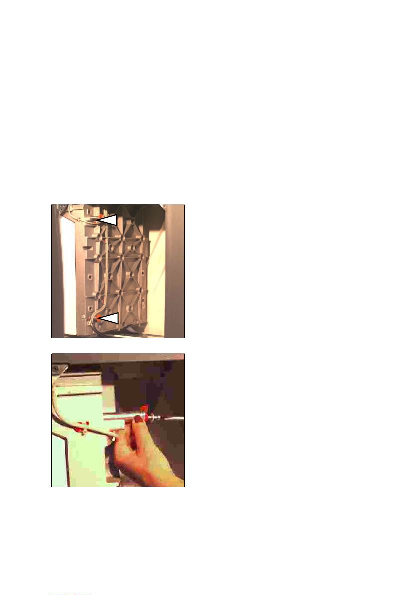
Unpacking and Installing
Attention: Do not touch the stray light
1
2
foil above.
Note: The camera carriage can not be
pushed back again by hand. It must/can
be left in this position. The software will
move the carriage back to its required
position.
17. Removing the restraining pins
Remove the screws on the shipping restraints with a flat screwdriver.
Now pull out the long screws and the
pins.
Nexscan F 4100/F 4200 – Operation 1– 9
Page 24
Unpacking and Installing
ABC
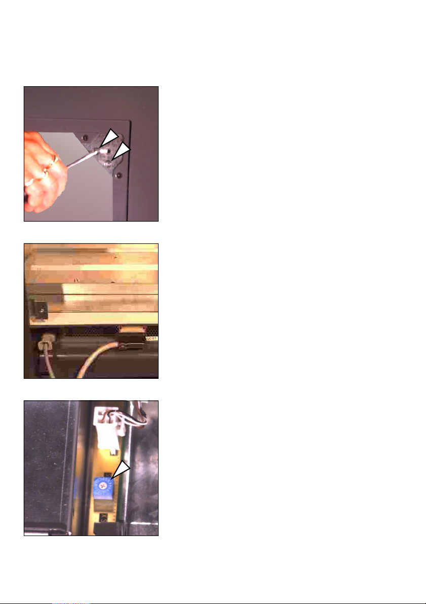
18. At the rear in the device, use a flat
screwdriver to remove the 2 vertical
slotted screws (not the double seams
screws!) to the upper right in the back
panel cutout (already carried out on the
left-hand side).
19. Connect the power cable and the SCSI
cable to the lower back of the device.
20. Setting the SCSI address
Set the correct SCSI address at the
lower back in the device. On delivery,
the scanner is set to SCSI address number 5. If this address is occupied, select
another number between 1 and 7.
Please note that if an internal CD-ROMdrive is connected in the computer,
address 3 can be used for this device. To
enter the setting you need a small flat
screwdriver.
1– 10 Edition September 2000
Page 25
ABC
Unpacking and Installing
21. Closing the back panel
Close the back panel again. Slide the
back panel into the two slits below and
fasten the 4 screws at the rear of the
device.
Make sure you have removed the CD
with the ICC profiles, which is attached
to the back panel, and that the cables
are laid in the back panel cutout and
not jammed anywhere.
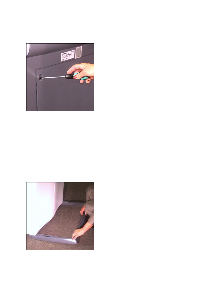
22. Final placement of the scanner
Now place the scanner in its final position on a secure and level surface.
23. Setting the height
If the scanner is not steady, you can
adjust the height of the front left and
right-hand feet. For this purpose, loosen the slotted screw from the outside –
one turn is sufficient – and you can
adjust the foot and secure it again.
24. Removing the base aperture
Slide the base aperture from the front
under the device until it engages. The
end clips for the aperture must penetrate into the rear covering.
Nexscan F 4100/F 4200 – Operation 1– 11
Page 26

Unpacking and Installing
2
1
ABC
Note: Keep all transport safety devices
in a safe place so that they can be reused if the device needs to be transported again.
Attention: Transportation without
transport safety devices can cause
damage to the device.
1– 12 Edition September 2000
Page 27

ABC
2 Connecting
Installation
After you have unpacked and moved your
Nexscan F 4100/F 4200 to its intended position, it
must be installed.
The following steps are required:
0
Connecting the Nexscan F 4100/F 4200 to the
workstation.
0
Connecting the Nexscan F 4100/F 4200 to the
power supply.
0
Switching on the Nexscan F 4100/F 4200.
0
Installing the software.
0
Install the calibration data.
Note: Any additional information on installation
can be obtained via the following Internet
2
address: http://www.heidelberg.com/
Connecting
Connecting the Nexscan F 4100/F 4200 to the workstation
Warning: The connection cable must be attached
in a voltage-free state. Only connect the power
33
1
Nexscan F 4100/F 4200 – Operation 2– 1
cables after connecting the connection cables.
This protects you against fatal electric shocks in
the case of a short circuit on one of the devices
and it protects the electronics system against
failure caused by voltage impulses during
potential differences.
Attention: Screened data cables with screened
plugs must be used, to adhere to radio
interference suppression regulations. Only use
connection cables and adapters approved by
Heidelberg.
Page 28

Connecting
Observe the length
of the SCSI cable!
ABC
The Nexscan F 4100/F 4200 has an SCSI
connection. You should always fit an SCSI
interface card to your computer, to which only
the scanner is connected. Commands which are
sent from the workstation to the Nexscan F 4100/
F 4200 and image data which is transferred from
the Nexscan F 4100/F 4200 to the workstation
pass through this link. The Nexscan F 4100/
F 4200 can be connected to any other SCSI device,
which has an SCSI connection, by means of the
connection cable – observe the length of the
cable when setting up the system.
Connect the SCSI cable for the Nexscan F 4100/
F 4200 to the SCSI port of your computer.
If, in addition to the Nexscan F 4100/F 4200 and
the operating unit, other SCSI devices are
connected to the SCSI bus, the Nexscan F 4100/
F 4200 must always be the last link in the chain,
as the SCSI bus in the Nexscan F 4100/F 4200 has
a terminator.
The SCSI bus must not exceed a total length of
6 m, otherwise you may encounter operational
difficulties.
2– 2 Edition September 2000
Page 29
ABC
3
3
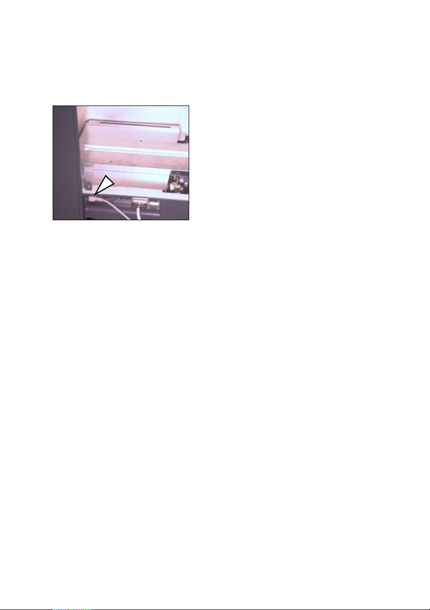
Connecting the Nexscan F 4100/F 4200 to the power supply
Note: The device is switched off
at both poles with the isolator
2
switch and is then deenergized, except for the
power cable connection up to
the switch.
Connect the device to the power supply
by means of the three-pin plug and
socket included in the delivery. The
device may only be operated when a
grounded conductor is connected.
Warning: Never plug in or remove the power cable
with wet hands and only ever get hold of it at the
plug. A damaged power cable can cause leakage
current and electric shocks. Protect the power
cable against damage. Never place any heavy
objects upon it and never squash it.
The electrical outlet is located on the rear of the
device underneath the service flap.
Connecting
The device automatically adapts itself for differing
voltage levels. These values are displayed on the
sticker on the rear of the device.
The operator has no access to the fuse.
Warning: The device may only be repaired by
Service personnel.
Do not install the device in the vicinity of airconditioning systems and protect it from moisture
and direct sunlight.Attention:
1
Nexscan F 4100/F 4200 – Operation 2– 3
Page 30

Connecting
ABC
Attention:
Unauthorized opening of the device's housing not
expressly described in the documentation and
improper repairs can lead to considerable danger
for the user.
Servicing work may only be performed by
authorized specialist personnel.
The respective accident prevention regulations
must be observed at all times.
Non-observance of accident prevention
regulations can lead to the loss of accident
insurance cover.
Use one of the power cables provided, appropriate
to the supply available, to connect the device to
the power supply. The local national regulations
must be observed when connecting the device
using power cables, which were not provided by
Heidelberg Prepress or when using connector
adapters.
Cable types used in USA and Canada must
correspond to the type SJT or better.
Attention:
1
2– 4 Edition September 2000
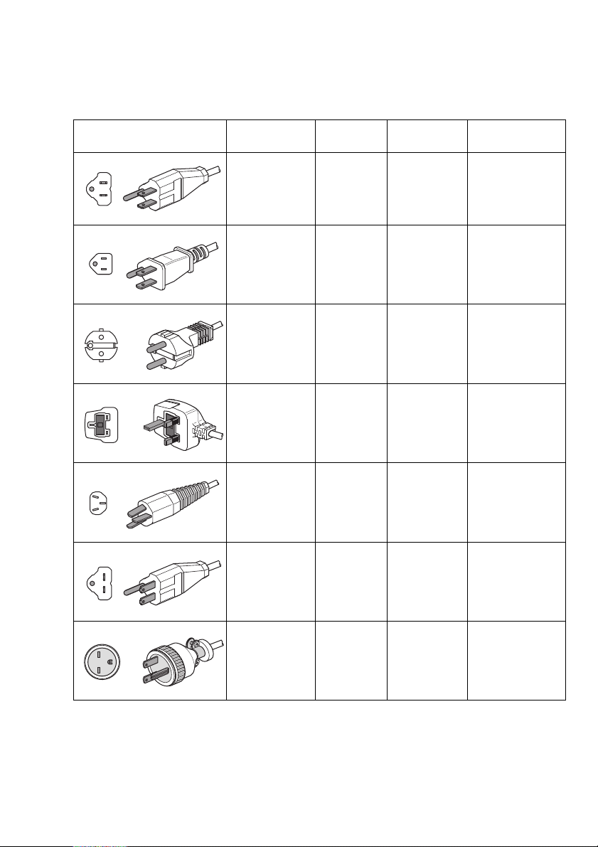
Taking national requirements into consideration,
select a cable from the table below if you want to
connect 100 V - 127 V or 200 V - 240 V AC.
Service personnel ensure the use of nationally
recognized power plugs in compliance with the
grounded conductor connection.
Notes regarding the power cable:
Page 31
ABC
Connecting
Type of Plug Country/
Region
North America
125V 10A
Japan
125V 10A
Europe
250V 10/16A
United
Kingdom
250V 10/16A
Australia
240V 10A
Voltage Regulations Type of Cable
115 - 120 V ANSI C 73.11
100 V JIS C3102
230 V IEC 83 <HAR> H05VV-F
220 - 240 V B.S. 1363
240 - 250 V A.S. C112 <HAR> H05VV-F
NEMA 5-15-P
IEC 83
UL 817
CSA C22.2
No.21
IEC 83
IEC 127
UL Listed
CSA Certified
Type SJT, 18AWG
JIS C3102
UL Listed
CSSA Certified
Type SJT, 18AWG
<HAR> H05VV-F
North America
250V 10A
Japan
250V 10A
240 V ANSI C 73.11
200 V JIS C 3102 JIS C310
NEMA 6-15-P
IEC 83
UL 198.6
UL Listed
CSA Certified
Type SJT, 18AWG
TYPE SJT
3/18AWG
Nexscan F 4100/F 4200 – Operation 2– 5
Page 32
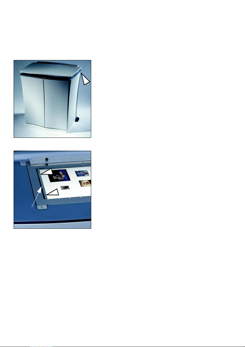
Connecting
Switching on the Nexscan F 4100/F 4200
Operate the power switch on the
Nexscan F 4100/F 4200. It is located at
the right on the rear of the device.
Please ensure that the scanner lid
remains closed during the switch-on
sequence and that there is nothing on
the white balance strip.
The scanner boots automatically and
carries out extensive tests during the
initialization phase. It is ready for
operation after approx. 3 minutes.You
White balance strips You can now
operate the scanner by means of the
software.
ABC
White balance strip
Installing the Newcolor Software
For an exact and detailed description of the
installation procedure, please refer to the
Newcolor XXXX Installation manual.
Installing the LinoColor Software
For an exact and detailed description of the
installation procedure, please refer to the
LinoColor Installation manual.
2– 6 Edition September 2000
Page 33

ABC
Note: To install the software, you need the CD with
the scanner ICC profiles, which is attached to the
2
back panel of the scanner.
Installing Calibration Data
Specific calibration data for your scanner is stored
in ICC profiles which are supplied on a CD. The CD
can be used for Newcolor and Linocolor (it is
attached to the back panel of the scanner).
Connecting
Keep the CD
safe!
Attention: Keep the CD in a safe place.
1
For Newcolor:
The CD is requested during the installation of
Newcolor XXXX and the ICC profiles are
transferred into the program. You can create new
ICC profiles yourself by means of the program.
For Linocolor:
If you wish to load the ICC profiles for your
scanner, click on ICC Profiles for Nexscan F4000
(from "Nexscan F4000 Profiles" CD) in the
Linocolor installation window.
The CD is requested during the installation
procedure.
Nexscan F 4100/F 4200 – Operation 2– 7
Page 34

Page 35
ABC
3 Product Description
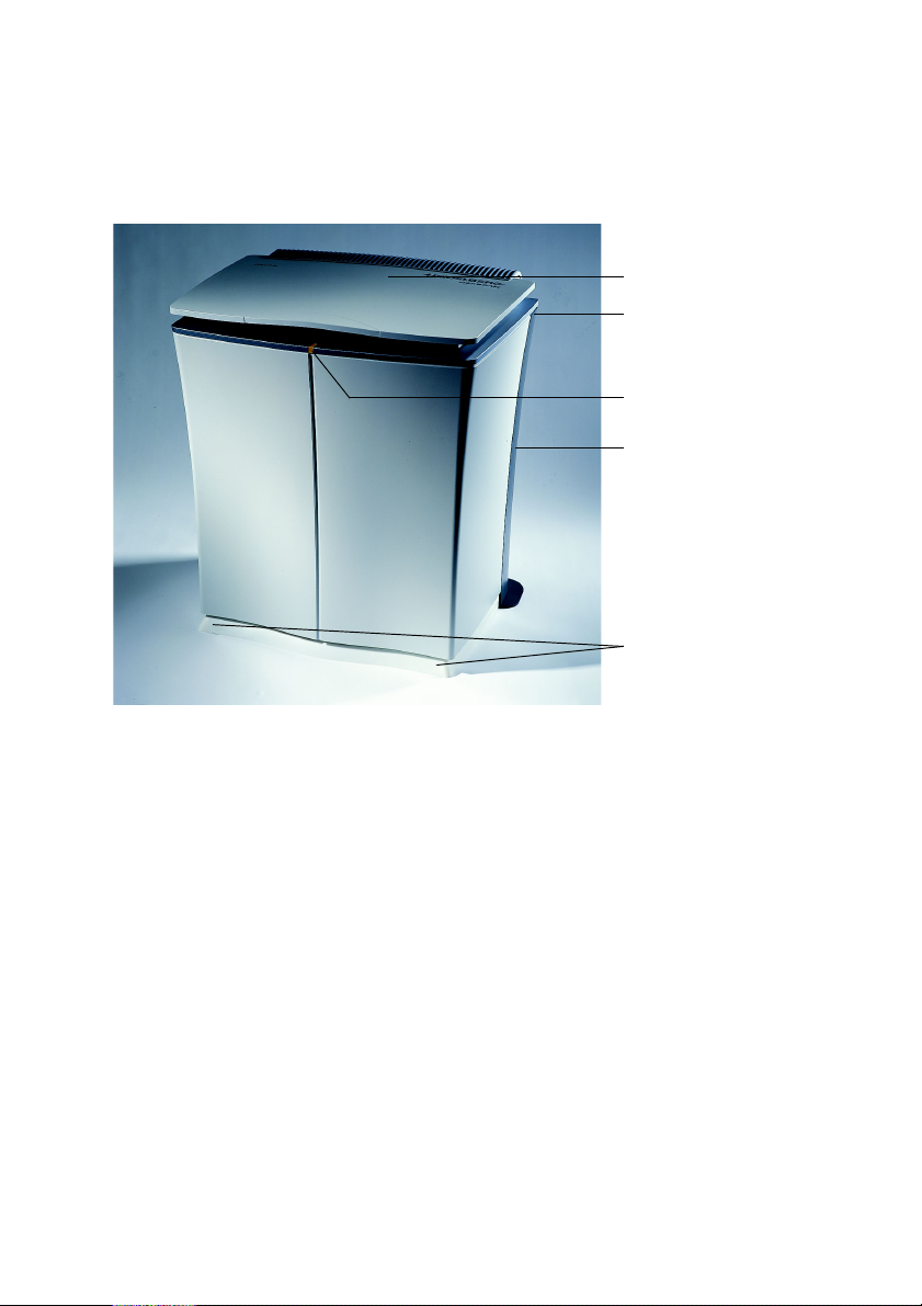
General view Nexscan F 4100/F 4200
Product Description
Scanner lid
Power switch
Pilot Lamp
Back panel
Gliding feet
(behind base
aperture)
Nexscan F 4100/F 4200 – Operation 3– 1
Page 36
Product Description
Product and Performance Features of the
Nexscan F 4100/F 4200
The Nexscan F 4100/F 4200 is a
universal, high-quality, fast CCD color
line scanner.
The Nexscan F 4100/F 4200 is operated
by means of the color image processing
programs Newcolor or Linocolor.
0
Originals
Reflection, transparency, color and
black-and-white, contone and line art,
positive and negative, screened printed
originals, real three-dimensional
objects.
0
Easy, production-oriented job preparation
If there are several trays, they can be prepared
away from the scanner, while the Nexscan F 4100/
F 4200 is scanning other jobs.
0
High quality and fast scans
ABC
The Nexscan F 4100/F 4200 has a CCD color line
with 3 x 8000 pixels. The Nexscan F 4200 also has
a special high-resolution CCD line for black-andwhite with 12,000 pixels. It ensures that a
particularly high optical resolution is obtained
when lineart is being scanned, e.g. in the Copy Dot
scan mode for the Copix scanning procedure.
3– 2 Edition September 2000
Page 37

ABC
Product Description
0
Sharp scans without time-consuming postediting
The Nexscan F 4100/F 4200 achieves an optical
resolution of 5080 dpi (F 4200 achieves 7040 dpi
for Copy Dot scan mode) with the RGB line.
Because of the internal interpolation hardware,
the optical system provides optimum resolutions
ranging from 100 to 10,800 dpi.
0
Optimized file sizes for the required output
format and screen
The size of the files sent to the user are calculated
precisely. The digital scan processor can calculate
scales from 20 % up to 2500 %.
0
Faster post-editing through precise image
rotation (by the software)
0
The Nexscan F 4100/F 4200is able to process
jobs quickly due to the JobAssistant batch
program.
0
Color format conversions and "on the fly"
calculation of color corrections during
scanning
0
Automatic focus
0
Automatic selection of apertures
0
Automatic focusing
0
Digital detail contrast without additional
processing time
0
ColorAssistant for good and consistent scans
(automatic image analysis)
0
Processing data from other sources
0
Modification of ICC profiles (Print Table Editor
and PrintOpen)
Nexscan F 4100/F 4200 – Operation 3– 3
Page 38

Product Description
Overall configuration
The system environment consists of an operating
unit, operating software and the output devices.
For ease of operation, work with 2 monitors, one
to display the software user interface and the
other for image display.
ABC
0
Creating Scitex-compatible data
0
Nexscan F 4100/F 4200 Copix
Separated film sets can be re-digitalized with
Copix which can be ordered as an optional
extra. Therefore, it is possible to scan archived
screened originals or to scan finished lithos for
a digital output. The digital data is used for
subsequent filmless post-editing, e.g. in a
layout program or on a computer-to-plate
production line.
3– 4 Edition September 2000
Page 39

ABC
Scanning principle
Product Description
0
Direct Capture Technology
When transparency originals are being scanned,
the translucent light is projected directly onto the
lens system and from there onto the scanning line
(CCD lines).
When reflection originals are being scanned, the
light reflected from the original is also projected
directly onto the lens and from there onto the
"CCD lines".
0
xyVariLens Optical System
The X/Y scanning principle ensures a high
resolution across the entire scanning area. The
originals can therefore be positioned anywhere
upon the scanning surface.
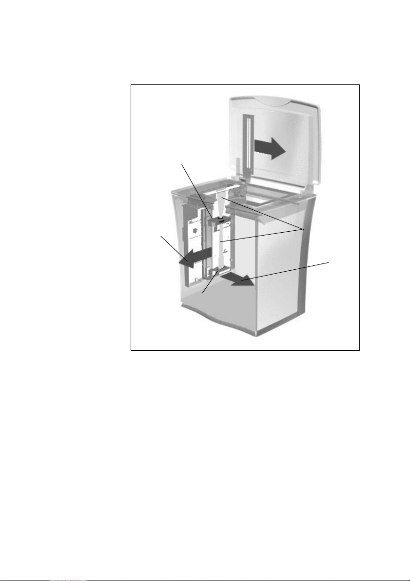
The lens system and the CCD lines are mounted on
sliding rails and can be positioned as required. In
this way, a lens is produced with a variable
reproduction scale.
This enables every original, in the resolution of
your choice, to make full use of the entire CCD
line.
Nexscan F 4100/F 4200 – Operation 3– 5
Page 40
Product Description
ABC
Lens system
Direction X
CCD line
The autofocus ensures that a sharp reproduction
of the original is always obtained, irrespective of
the distance from the glass plate. This means that
slides with all types of frames can be scanned
without any problem, even in the slide tray.
Light ray
Direction Y
3– 6 Edition September 2000
Page 41
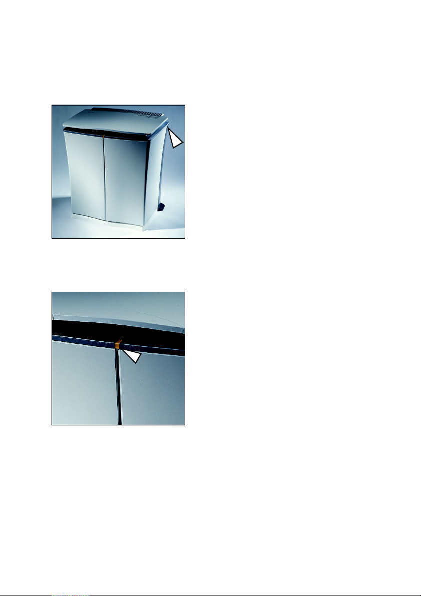
ABC
Power Switch
Pilot Lamp
Product Description
The power switch is located to the right
at the rear of the unit.
The pilot lamp lights up continuously if
the scanner is switched ON and ready
for operation.
Note: The device is switched off
at both poles with the isolator
2
switch and is then deenergized, except for the
power cable connection up to
the switch.
Flashing slowly:
Scanner is busy, e.g. scanning run in
progress.
Lit continuously:
Scanner is switched on and ready for
operation
Flashing quickly:
Error
Nexscan F 4100/F 4200 – Operation 3– 7
Page 42
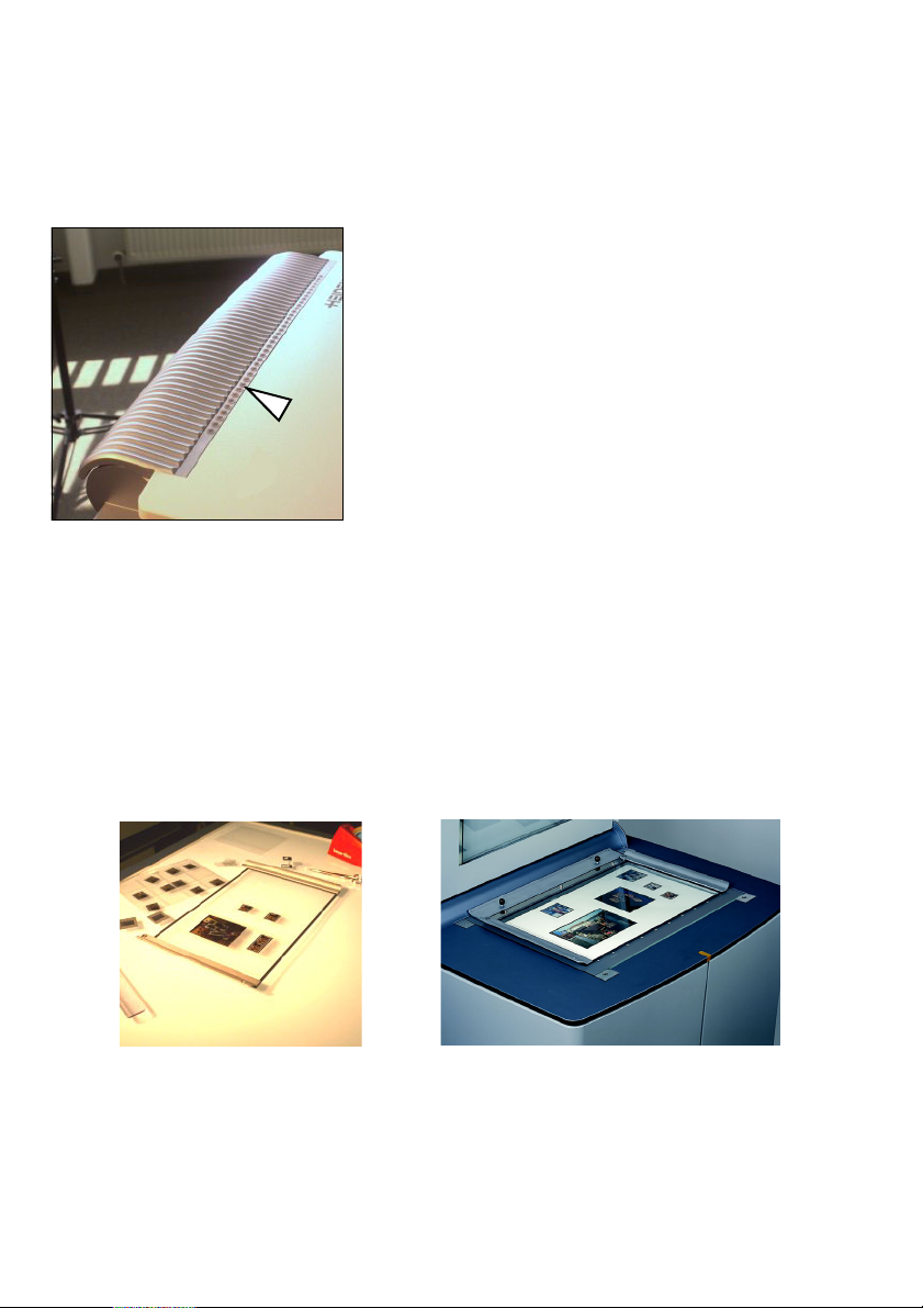
Product Description
Scanning Progress Indicator
The position of the feed is displayed by
the pilot lamp when scanning.
Universal tray
The universal tray – size: 315 mm x 457 mm –
consists of a glass plate and ergonomically shaped
handles. The transparency and reflection
originals are placed here.
ABC
Attention: Both sides of the tray are anti-Newton
1
Universal tray as
3– 8 Edition September 2000
coated – do not scrape or scratch!
Universal tray with mounted
originals in the scanner
Page 43
ABC
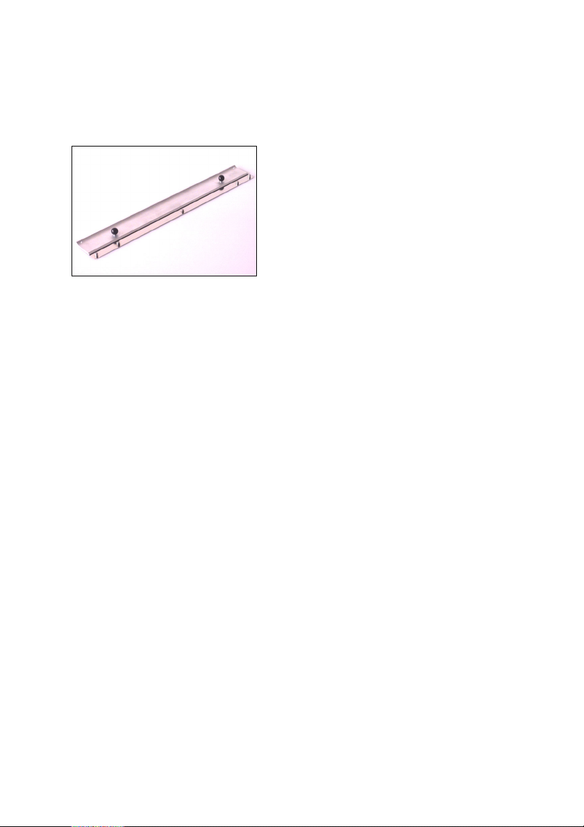
Mounting Rail
Scanning Area
Product Description
The mounting rail is placed into the
scanner in 2 restraining pins.
It helps to fix
- the universal tray
- Copix films
- the slide tray
- the passepartout
Formats:
Reflection: 315 mm x 457 mm
12.4" x 18"
Transparency: 315 mm x 457 mm
12.4" x 18"
Screens
24 to 80 screen
Scales
Scale: 20% to 2500%
Line art: 50% to 2500%
B/W-contone: 20% to 2500%
Color: 20% to 2500%
Nexscan F 4100/F 4200 – Operation 3– 9
Page 44

Product Description
Scanning Speed
The scanning times depend on the following
parameters:
- Speed with which lines are scanned
- Scanning mode
- Size of original
-Scale
- Screen
- Quality chosen
- Capacity of the workstation
Illumination of originals
The scanning area is illuminated from below to
enable a visual inspection of the mounted
transparency originals.
Through this, the mounting procedure in the unit
is simplified as well. The originals are
automatically illuminated when the scanner is
switched on.
ABC
3– 10 Edition September 2000
Page 45

ABC
Working with the Nexscan F 4100/F 4200
4 Working with the Nexscan F 4100/F 4200
Operating Sequence
1. Preparation for production
2. Possible tray preparation
3. Position the originals
4. Secure the originals
5. Open the scanner lid
6. Possible tray insertion
7. Original is Flat
8. Close Scanner Lid
9. Perform the scan
If you wish to obtain precise, geometric accuracy
for both pre-scan and fine scan, then you should
not remove the universal tray between these two runs!
Preparation for Production
0
Operate the on/off switch on the
device.
0
Wait for the warm up period of
approx. 3 minutes. The pilot lamp is
illuminated constantly and indicates
that the device is ready for operation.
0
Switch the computer and monitor ON
and run the software.
Nexscan F 4100/F 4200 – Operation 4– 1
Page 46
Working with the Nexscan F 4100/F 4200
Preparing the Tray
0
Both sides of the tray have an antiNewton coating – do not scrape or
scratch.
0
Clean the universal tray.
0
Clean the originals.
(Refer to the Service and Maintenance
chapter).
Positioning the Originals
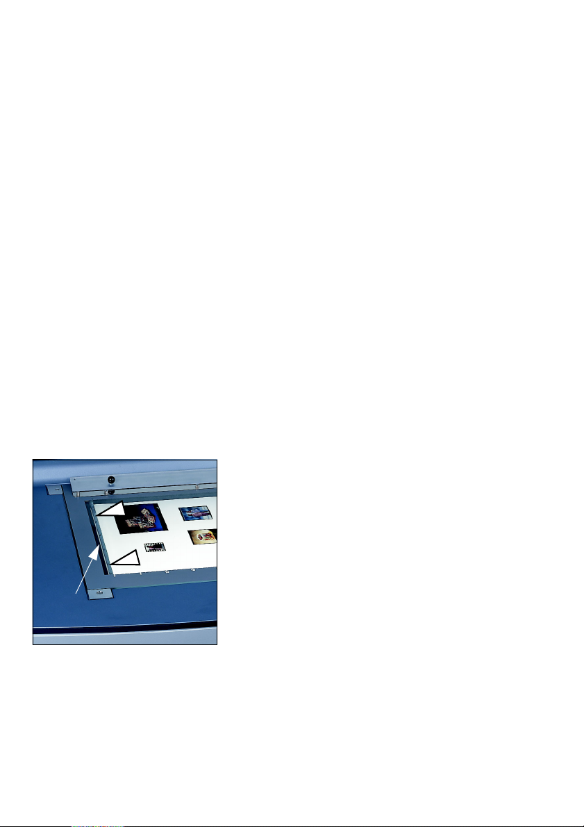
Attention: No originals must be
mounted on the white balance strip,
1
On the Glass Plate in the Device
otherwise the white balance can not be
carried out.
0
Transparency
ABC
Open the scanner lid. The originals can
be placed as needed on the glass plate.
The film coating must be against the
glass plate (profile view).
Attention: Mounting originals
with liquids such as oil, gel or
1
White balance strip
(do not mount on it)
4– 2 Edition September 2000
0
Reflection
Place the original with the motif onto
the glass plate with the reverse side
facing upwards. The originals can be
placed as needed on the glass plate.
film cleaner may only be
carried out outside the device
on the universal tray.
Page 47
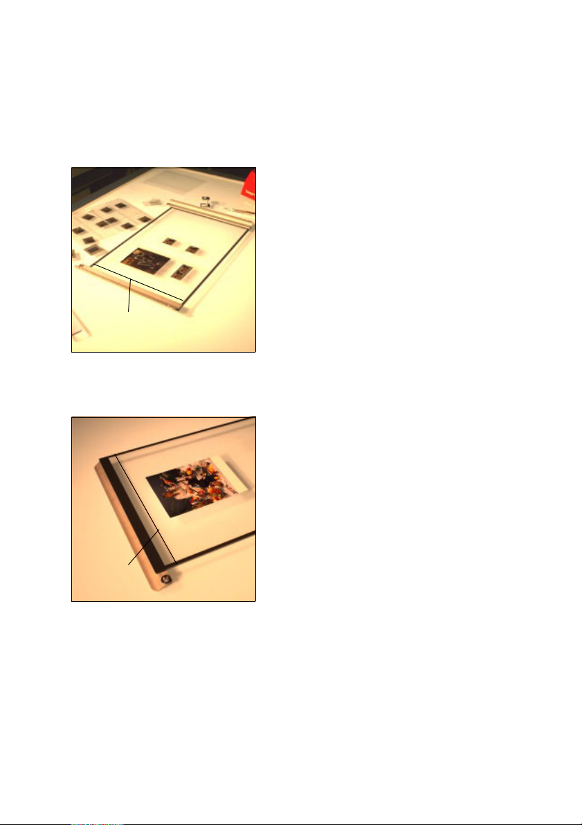
ABC
On the Universal Tray
White balance strip
(do not mount on it)
Working with the Nexscan F 4100/F 4200
0
Transparency
The originals can be positioned
anywhere. The film coating must be in
contact with the glass plate (right
reading view). After mounting, place
the universal tray into the mounting rail
guide pins in the scanner.
Both sides of the tray have an antiNewton coating – do not scrape or
scratch.
TIP: Place the tray onto a screen film
and align the originals according to this
film.
0
Reflection
Take the tray out of the scanner and
rotate it. Now mount the originals with
the motif facing upwards and the
reverse facing the glass plate on the
tray. The originals can be positioned
anywhere. Now place the tray the right
way round into the scanner.
White balance strip
(do not mount on it)
Nexscan F 4100/F 4200 – Operation 4– 3
Page 48
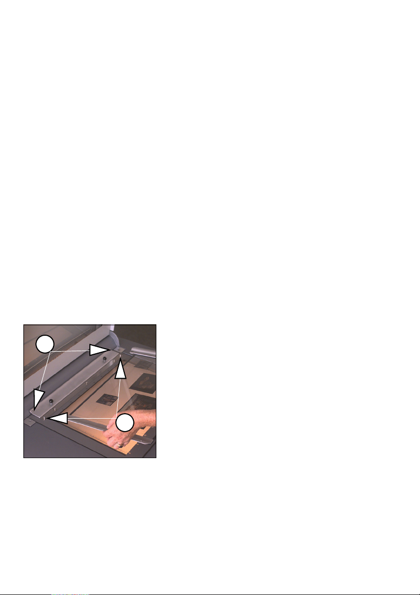
Working with the Nexscan F 4100/F 4200
Securing the Originals
Lightly press the originals onto the glass plate and
secure them with adhesive tape or foil.
If the image is to be scanned wrong-reading
(e.g. in comparison to pre/coarse scan), you can
activate the desired mirroring by selecting a
Mirroring
Best Possible
contrast
Inserting the Tray
1
mirroring in the software.
Such mirroring does not cause any loss in quality!
To obtain the bestpossible contrast and the
highest density, you should use passepartouts
which cover up the parts of the image outside the
scanning area when carrying out transparency
scanning.
The Passepartout frames should be at least
25 mm wide.
Insert the mounting rail into the scanner
guide pins (1). You can then place the
tray into the mounting rail guide pins for
the tray (2).
ABC
2
4– 4 Edition September 2000
Page 49

ABC
Close Scanner Lid
Working with the Nexscan F 4100/F 4200
Close the scanner lid and make all further settings
in the software.
Nexscan F 4100/F 4200 – Operation 4– 5
Page 50

Working with the Nexscan F 4100/F 4200
Scanning Process
After you have mounted the originals, the actual
scanning process can begin.
The scanning process is controlled via a PC or
Macintosh computer.
For Newcolor:
ABC
first fast scan
first fast scan
Batch Operation
ICC profiles
Note: The most important settings for the"First
fast scan" can be found in the documentation:
2
0
Newcolor 7000 Workflow, chapter 2.
For further information, refer to:
0
Newcolor 7000 – Reference
For Linocolor:
Note: The most important settings for the"First
fast scan" can be found in the documentation:
2
0
LinoColor – User's Guide, chapter 2.
For further information, refer to:
0
Linocolor – Reference
For information on batch processing, scheduling
jobs in the print queue etc., refer to:
0
JobAssistant – Operation
Both latter mentioned documents are available on
your target volume in the documentation folder
after Linocolor has been installed.
You can generate your own ICC profiles using the
programs from ColorOpen, such as
0
Printopen
0
Scanopen
0
Viewopen
4– 6 Edition September 2000
Page 51

ABC
Working with the Nexscan F 4100/F 4200
For further information, refer to the respective
documentation.
Note: The Nexscan F 4100/F 4200 is a highprecision device which reproduces originals with
2
a resolution of up to 5/1000 of a mm. For this
reason you should not mess around with the unit
during the scanning sequence (knock against it,
place objects on it or remove objects).
Nexscan F 4100/F 4200 – Operation 4– 7
Page 52

Working with the Nexscan F 4100/F 4200
Scanning Three-Dimensional Objects
The depth of focus of the Nexscan F 4100/F 4200
is very high in the range of 20% to 300 % due to
the "xyVariLens optical system" and the
autofocus.
This means that you can directly scan real –
material objects (3D-objects), e.g.: wristwatches,
coins, jewelry, flatware, books, small mechanical
or electronic parts, fabric, carpet, or wallpaper
patterns, etc.
Do not scan wet or dusty objects!
The objects may not be heavier than 5 kg.
Placing Objects
Place the objects on the glass surface with the
visible/front side facing downwards.
The feed is very smooth, therefore you do not need
to secure the objects.
ABC
Prepare a background to cover the objects with.
Recommendation: Cardboard or fabric which
match the color of the object(s).
Selecting Reflection Scanning Mode
You have to select the Reflection scanning mode to
scan the objects.
You can use the entire scan area of
315 mm x 457 mm (12.4" x 18") for scanning.
4– 8 Edition September 2000
Page 53

ABC
Selecting the Quality
For Newcolor: The autofocus function is active for
all quality modes, i.e. for good, very good and
excellent.
For Linocolor: Select either excellent or excellent
x4 so that the autofocus function is activated.
If objects have reflecting surfaces, blooming with
colored edges may occur which should be
retouched.
Working with the Nexscan F 4100/F 4200
Mounting with Oil, Film Cleaner or Gel
Attention: Mounting originals with liquids such as
oil, gel or film cleaner must only be carried out
1
outside the device on the universal tray.
If the originals are damaged or if they are of poor
quality, use a Film cleaner or gel. This makes
scratches, film damage and other flaws invisible.
We especially recommend the use of Film cleaner
as time-consuming cleaning of the originals after
scanning is no longer necessary.
Mounting takes place in the following order:
Film cleaner/gel/oil – original – film cleaner/gel/
oil – foil.
Nexscan F 4100/F 4200 – Operation 4– 9
Page 54
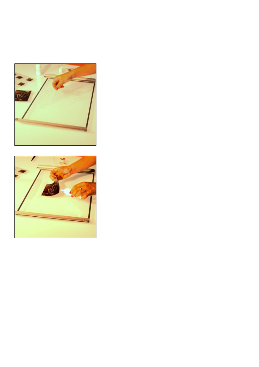
Working with the Nexscan F 4100/F 4200
Mounting Procedure
0
First glue the foil onto the glass and
fold it away to the rear. Use the
adhesive tapes as hinges.
0
Do the same with the original. Place
the original in such a way that it can
later be completely covered with foil.
0
Apply some Film cleaner, oil or gel to
the glass plate. The amount used
depends on the size of the original
(experimental value).
0
Fold the original onto the glass plate
screened with Film cleaner, oil or gel
so that the film layer comes in contact
with the screened plate.
0
Lightly press the original down onto
the drop of film cleaner or oil.
ABC
4– 10 Edition September 2000
Page 55
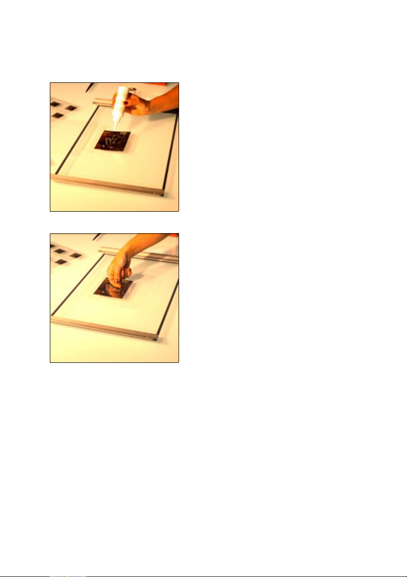
ABC
Working with the Nexscan F 4100/F 4200
0
Apply some film cleaner, oil or gel to
the original. The amount used depends
on the size of the original
(experimental value).
0
Fold and press the mounting foil onto
the original.
0
Remove any air bubbles by smoothing
over the original with your fingers from
the middle to the edges. By doing this,
you spread the liquid.
0
Insert the tray into the scanner.
Nexscan F 4100/F 4200 – Operation 4– 11
Page 56
Working with the Nexscan F 4100/F 4200
Mounting Selection
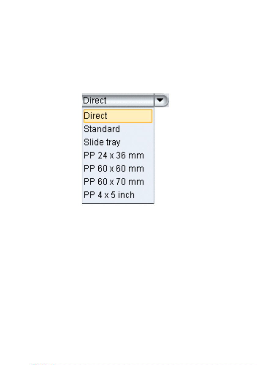
For Newcolor:
You will find the selection options in the Scan tray
window under Direct...
ABC
Select:
0
Direct,
if you want to mount directly into the scanner
and not use the tray
0
Standard,
if you want to work with the Universal tray
0
Slide,
if you want to work with the slide tray
0
Passepartout,
if you want to work with a passepartout
4– 12 Edition September 2000
Page 57
ABC
Working with the Nexscan F 4100/F 4200
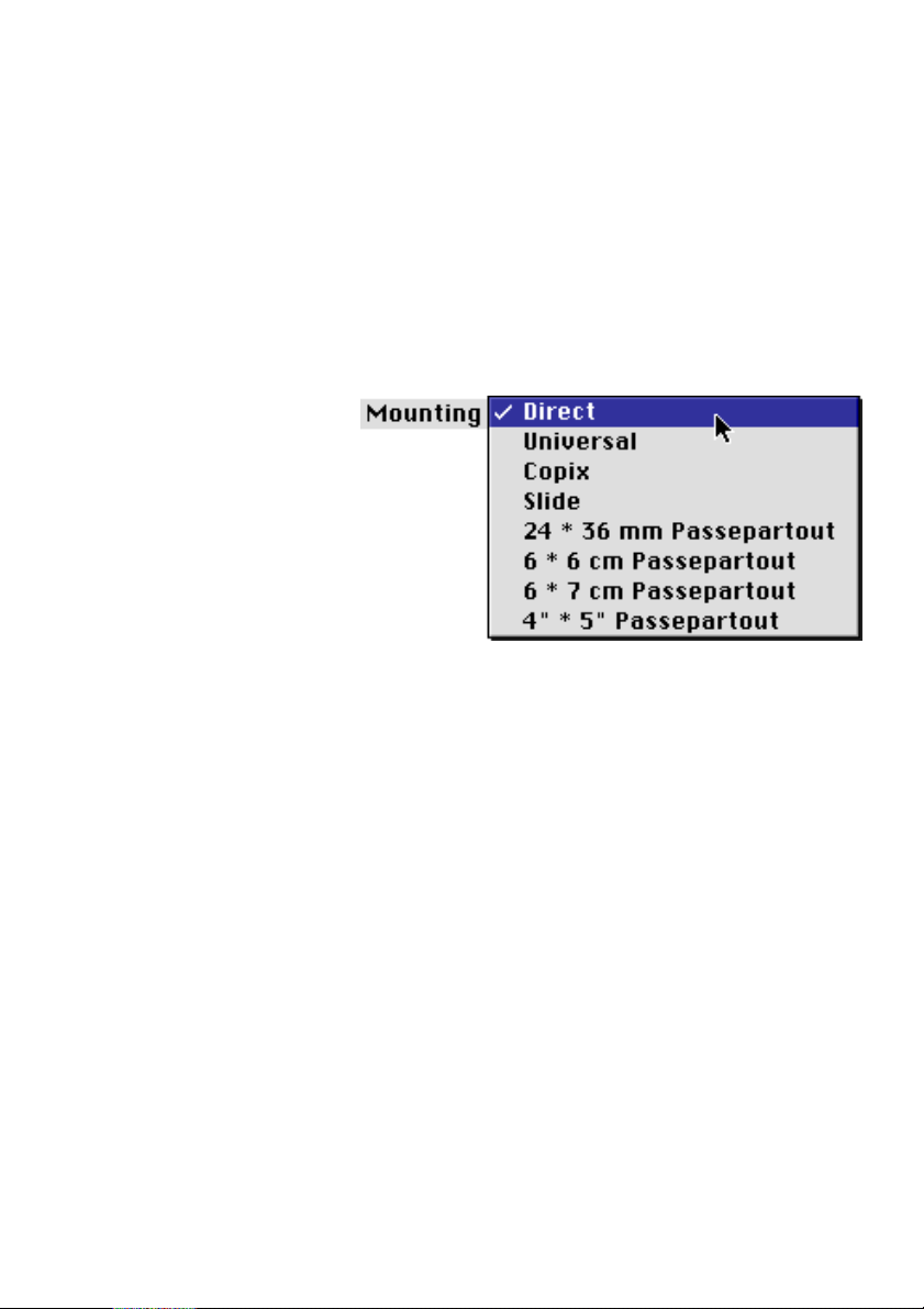
For Linocolor:
Select the Nexscan F4000 Tray window in the
Import > Source > Nexscan F4000 menu. A
window appears in which the scanning area is
represented. In the scanning area, you can select
the different sorts of mounting with which you
would like to scan under Mounting.
Select:
0
Direct,
if you want to mount directly into the scanner
and not use the tray
0
Universal,
if you want to work with the Universal tray
0
Copix,
if you want to redigitalize separation films in
Copix mode
0
Slide,
if you want to work with the slide tray
0
Passepartout,
if you want to work with a passepartout
Nexscan F 4100/F 4200 – Operation 4– 13
Page 58

Working with the Nexscan F 4100/F 4200
Light optimization
In order to obtain a scan of the highest quality, the
lamps must have a constant light stability
throughout the entire scanning process. If there is
not a constant light stability before a scan, the
following message appears:
Light optimization running (in the case of
Linocolor with the addition: – Skip with ”Cancel”).
If you cancel this message, there could be a
minimal loss in quality in the case of critical
originals containing, for example, large color
areas of the same density or shading. A loss in
quality was not discerned when using normal
originals.
Tips to avoid the message:
1. The message also appears when switching
between transparency and reflection illumination.
Unnecessary switching over of the illumination
modes should therefore be avoided. Process all
transparency scans first and then the reflection
scans or vice versa.
ABC
2. As reflection lamps switch off quicker than
transparency lamps, the reflection scans should
be processed swiftly. This avoids forced switching
off of the reflection lights (thus no new message on
switching on the lamps).
3. On selecting the scanning quality Very good,
Excellent and 4x Excellent (only for Linocolor), the
light optimization function is activated. The
scanning quality Good is therefore recommended
for non-critical originals as the message does not
appear in this case. This also applies to the course
scan (prescan).
4– 14 Edition September 2000
Page 59
ABC
Working with the Nexscan F 4100/F 4200
Special scanner functions
Reloading the Scanner Software (for Newcolor)
This procedure must be performed e.g. when you
have changed scanner software from Linocolor to
Newcolor.
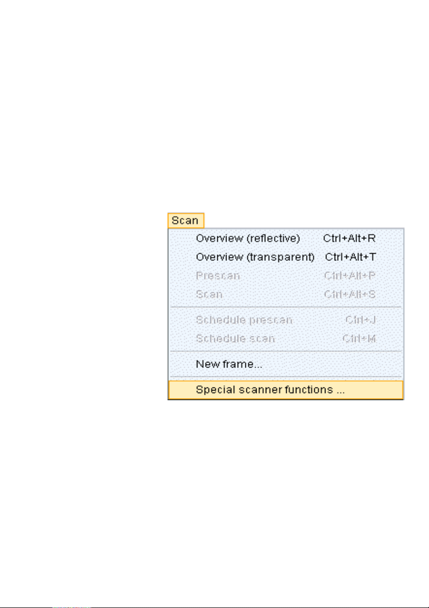
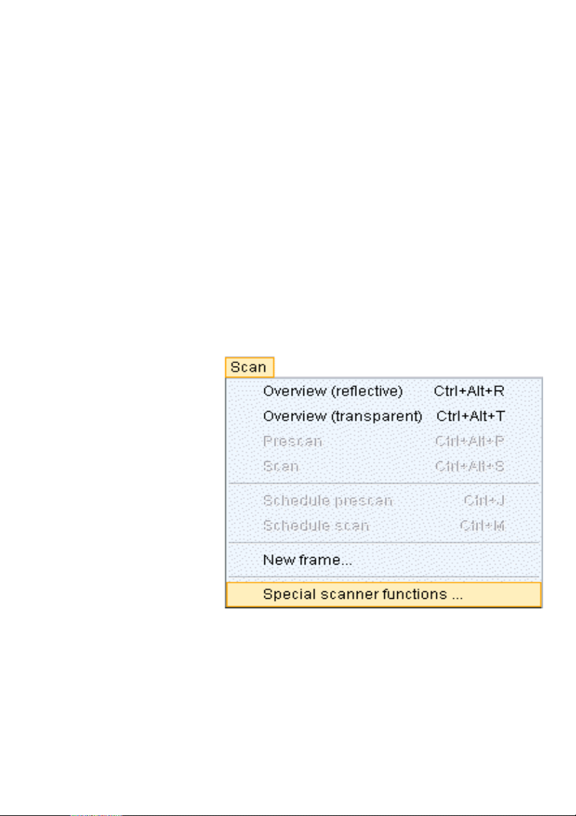
Select the menu item Scan > Special scanner
functions...
Nexscan F 4100/F 4200 – Operation 4– 15
Page 60
Working with the Nexscan F 4100/F 4200
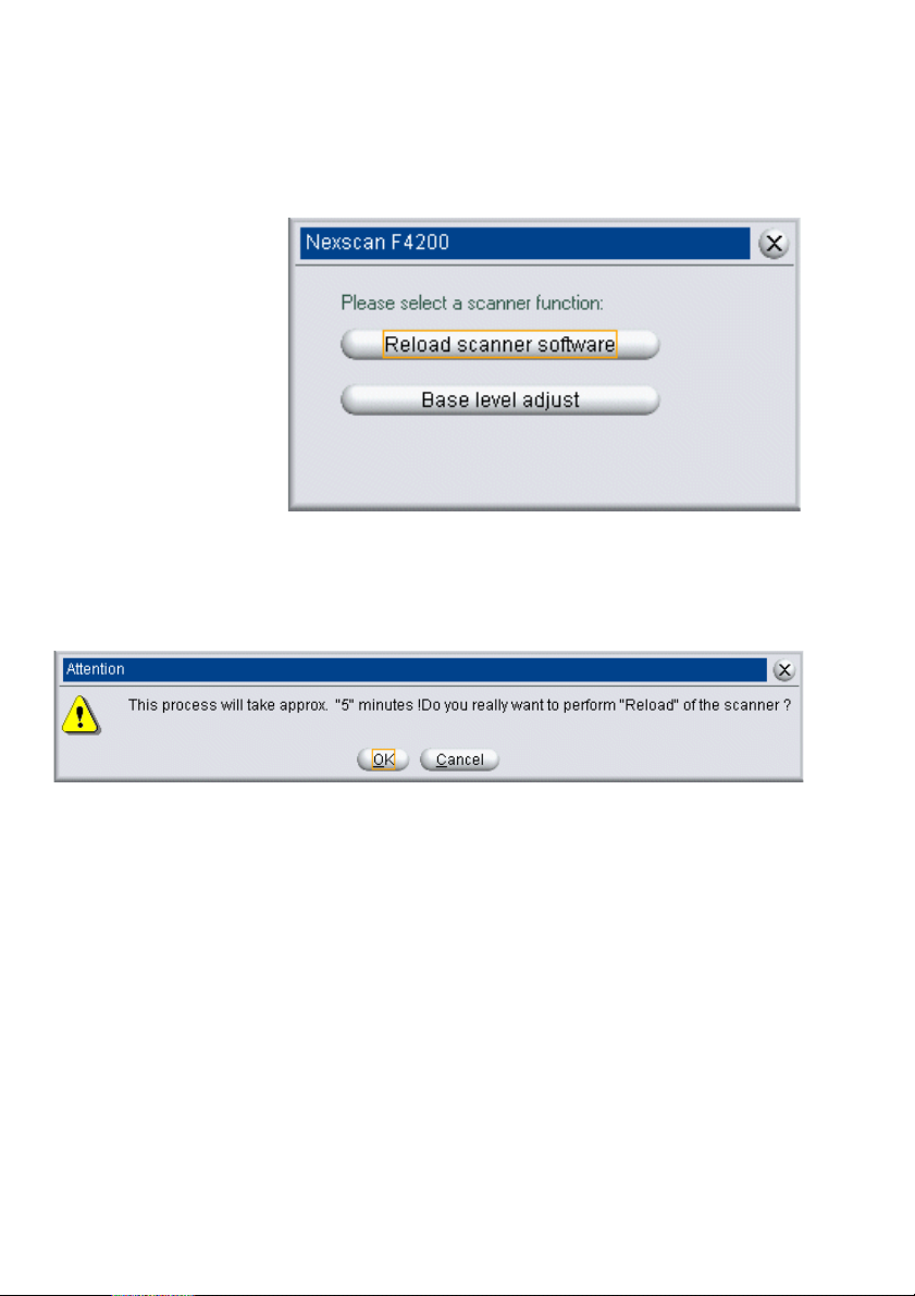
... Reload scanner software.
Click Reload scanner software. The following
message appears:
ABC
Click OK.
4– 16 Edition September 2000
Page 61
ABC
Performing a Basic Level Adjustment (for Newcolor)
Basic level adjustment is performed by Heidelberg
and normally does not have to be repeated.
It is possible that a base level adjustment becomes
necessary as part of an installation procedure or
that a particular error message at the monitor
requires it. In these cases, proceed as follows:
Remove the scanning tray from the Scanner. Clean
the glass surface. It must be absolutely clean,
especially the white balance strip.
Select the menu item Scan > Special scanner
functions...
Working with the Nexscan F 4100/F 4200
Nexscan F 4100/F 4200 – Operation 4– 17
Page 62
Working with the Nexscan F 4100/F 4200
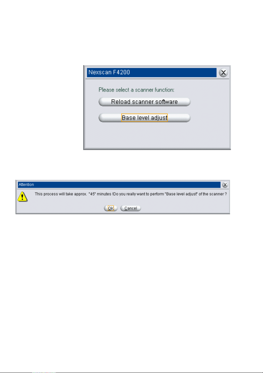
... Base level adjust.
Click on Base level adjust. The following message
appears:
ABC
Click OK.
4– 18 Edition September 2000
Page 63
ABC
Performing a Basic Level Adjustment (for Linocolor)
Basic level adjustment is performed by Heidelberg
Prepress and normally does not have to be
repeated.
It is possible that a base level adjustment becomes
necessary as part of an installation procedure or
that a particular error message at the monitor
requires it. In these cases, proceed as follows:
Remove the scanning tray from the Scanner. Clean
the glass surface. It must be absolutely clean,
especially the white balance strip.
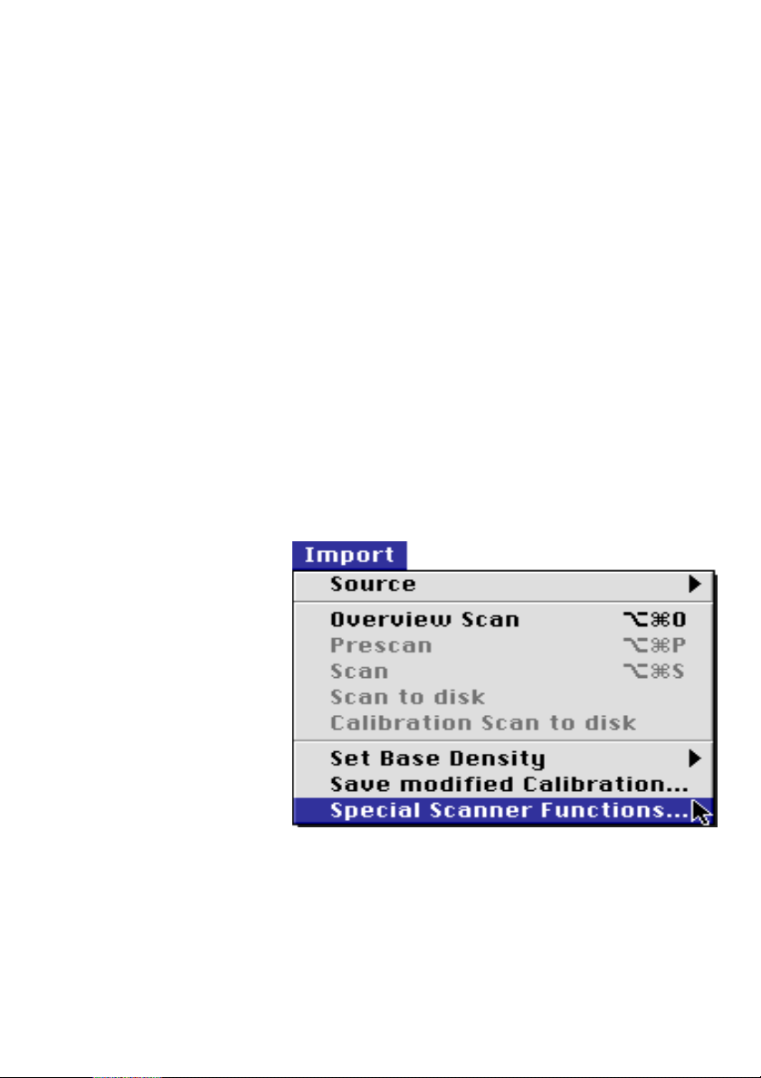
You have selected Import > Source > Nexscan
F4000 menu in Linocolor.
Select the menu item Special scanner functions...
in the Import menu.
Working with the Nexscan F 4100/F 4200
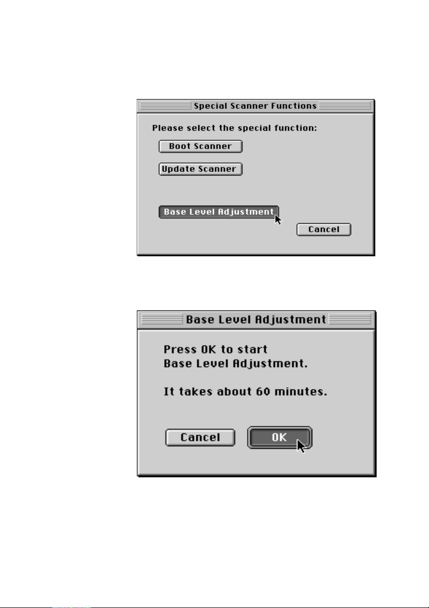
The following dialog window appears:
Nexscan F 4100/F 4200 – Operation 4– 19
Page 64
Working with the Nexscan F 4100/F 4200
Click on Base level adjustment.
Click OK. The adjustment procedure takes about
60 minutes. The Nexscan F 4100/F 4200 is
automatically initialized after this.
ABC
4– 20 Edition September 2000
Page 65
ABC
Resetting the Scanner (for Linocolor)
There may be different reasons for having to reset
the scanner:
- there is an error message
- the scanner is not working
- a new operating software has to be loaded
In these cases, proceed as follows:
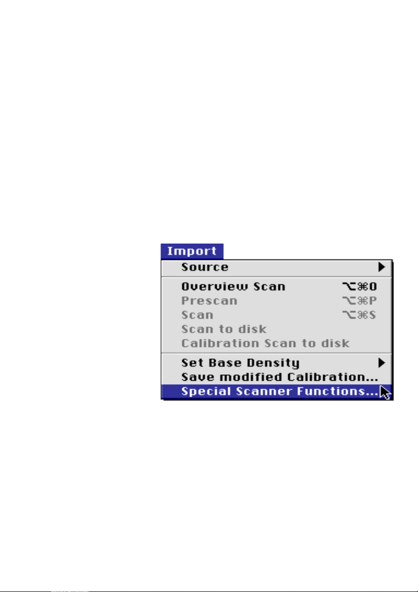
You have selected Import > Source > Nexscan
F4000 menu in Linocolor.
Select the menu item Special scanner functions...
in the Import menu.
Working with the Nexscan F 4100/F 4200
Nexscan F 4100/F 4200 – Operation 4– 21
Page 66
Working with the Nexscan F 4100/F 4200
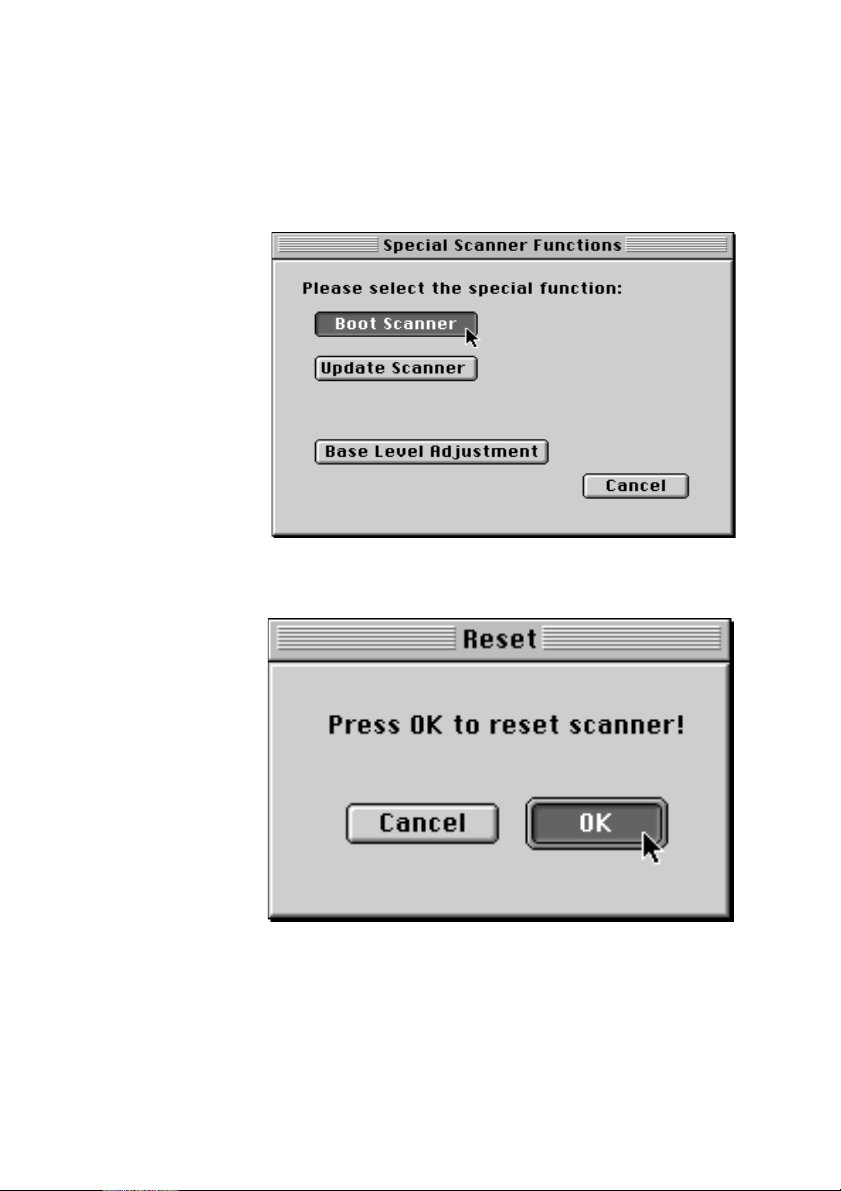
The following dialog window appears:
Click Boot Scanner.
Finally, click OK. The scanner is reset and
initialized.
ABC
4– 22 Edition September 2000
Page 67
ABC
Updating the Scanner (for Linocolor)
This function is essential if you should have any
problems with a Linocolor version and want to use
another version.
Proceed as follows:
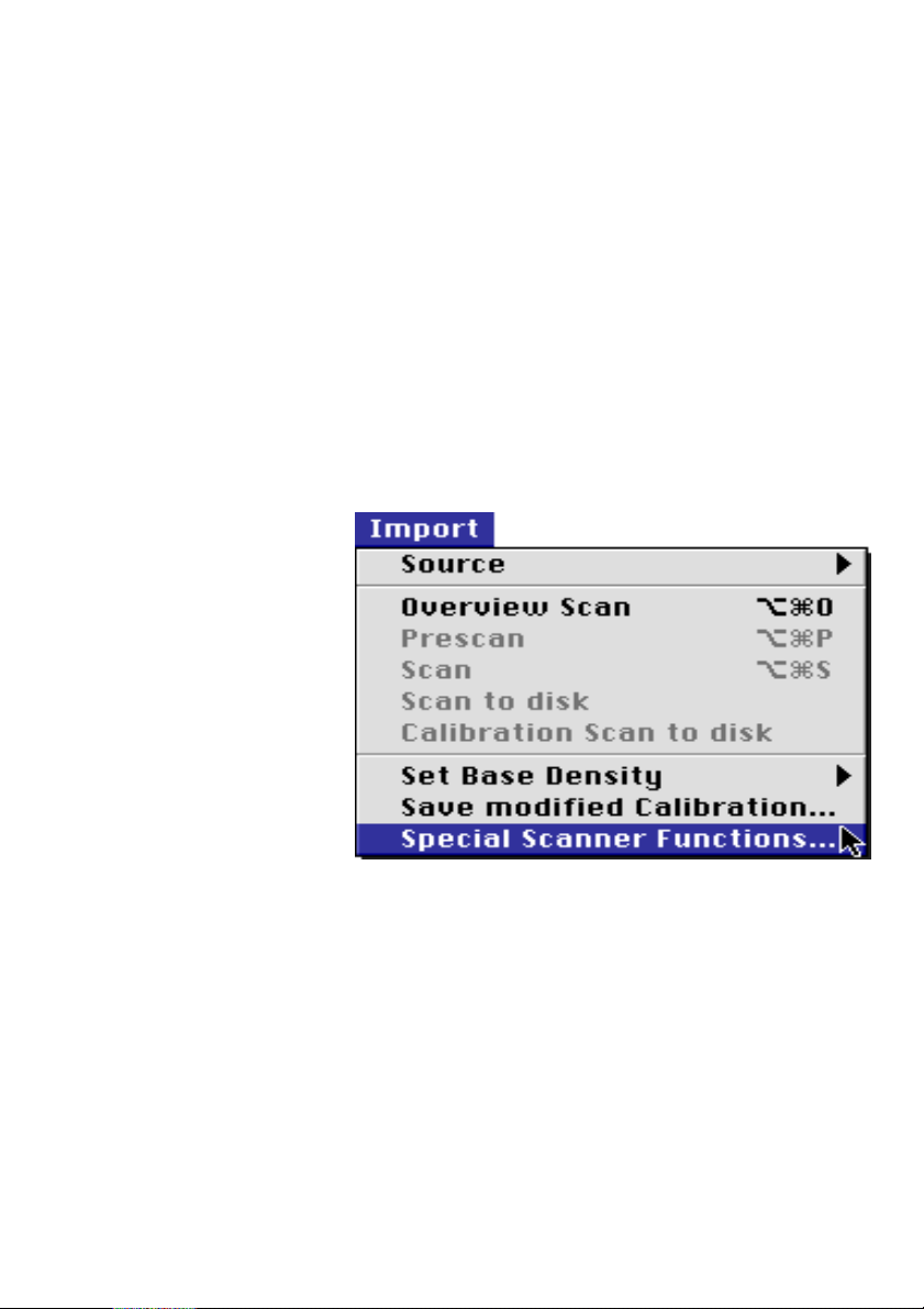
You have selected the other version in the
Import > Source > Nexscan F4000 menu in
Linocolor.
Select the menu item Special scanner functions...
in the Import menu.
Working with the Nexscan F 4100/F 4200
Nexscan F 4100/F 4200 – Operation 4– 23
Page 68
Working with the Nexscan F 4100/F 4200
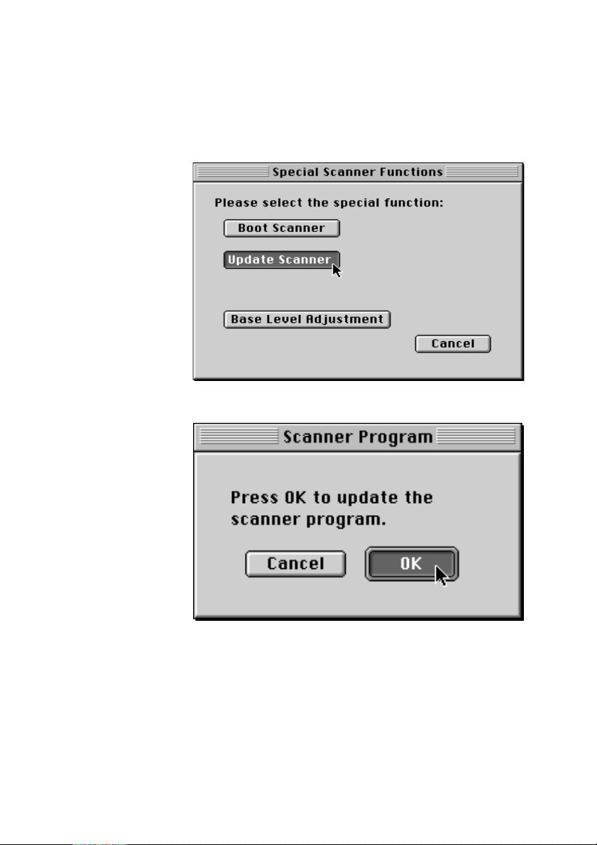
The following dialog window appears:
Click Update Scanner.
Click OK. The scanner program is updated.
ABC
4– 24 Edition September 2000
Page 69
ABC
Working with the Slide Tray
For Newcolor:
0
Scanner Settings
Prior to scanning, click Job Preparation and
adjust the settings under Scan Setup that you
want to apply to all inserted slides, e.g. name
assignment, quality and scale.
0
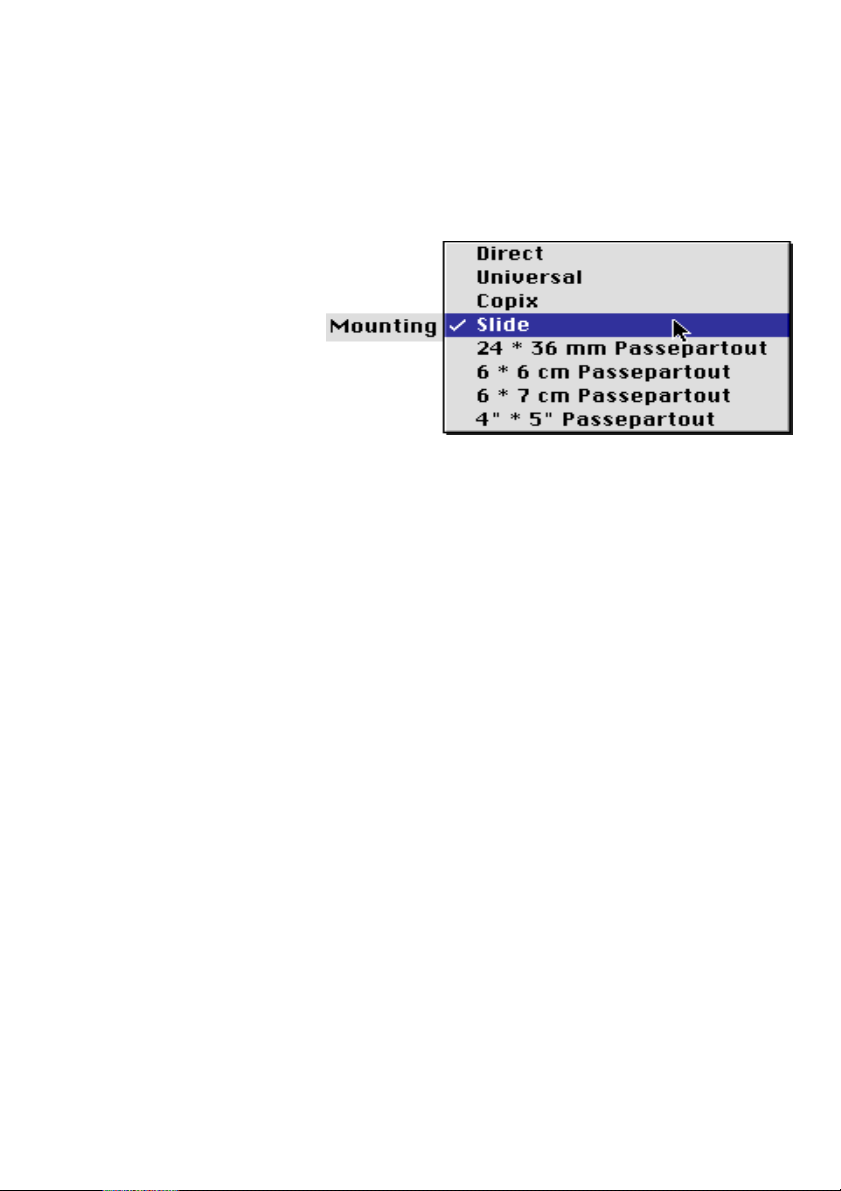
Select Slide tray mounting in the Scan tray
window.
Working with the Nexscan F 4100/F 4200
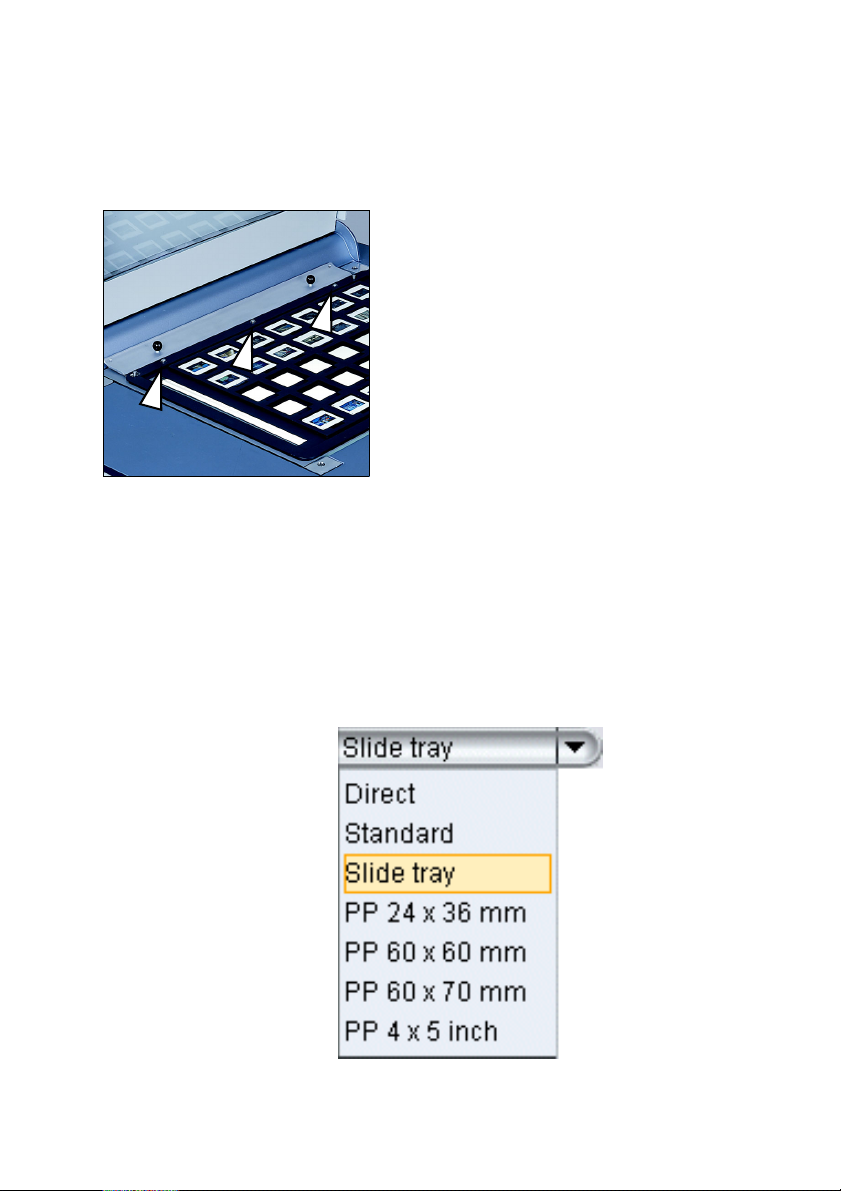
You can insert 35 framed small format
passepartout slides (24 x 36 mm) into
the slide tray. The process of inserting
the slide tray into the scanner is the
same as for the universal tray. The tray
must be placed into the dowel pins for
the mounting rail so that the white
balance strips are not covered.
The scan software automatically
recognizes in which recess the slides are
located and if they have been inserted in
portrait or landscape format.
Nexscan F 4100/F 4200 – Operation 4– 25
Page 70

Working with the Nexscan F 4100/F 4200
0
Name Assignment
During the name allocation, Newcolor allocates
ascending numbers to the slides, e.g.
Image01... Image35. However, you can also
individually change the name, e.g. for a certain
customer. This should be done before
scanning. If the count for a certain name does
not start at 01, a frame of this name and
number already exists. This can also be in a
different mounting mode, e.g. not in Slide tray
but in Direct.
More information about name allocation can
be found in the LinoColor documentation.
0
Perform an overview scan (transparent). Image
frames are created and it is automatically
detected whether the slides have been inserted
in landscape or portrait format.
0
You can now select the frames from which you
want to create low-resolution or highresolution scans. If you are performing lowresolution scans, you may be able to perform
further settings for the subsequent highresolution scans. Then perform the highresolution scans.
0
Job Assistant
Another possibility is to process the jobs by
means of JobAssistant. In this case, you will
perform an overview scan and enter all
standard settings for the jobs. You will then
select the jobs (with Ctrl + a) and plan them as
low-resolution scans (if you want to perform
further settings) or directly as high-resolution
scans. The additional procedures are described
in the Newcolor documentation.
ABC
4– 26 Edition September 2000
Page 71
ABC
S
Scanner Settings
Name Assignment
canning Options
Working with the Nexscan F 4100/F 4200
For Linocolor:
Select Mounting > Slide in Linocolor.
0
Prior to scanning, adjust the settings under
Nexscan F4000 settings that you want to apply
to all inserted slides, e.g. scanning mode and
scale.
0
Linocolor automatically assigns a name and
ascending numbers to the slides, e.g.
Image01... Image35. However, you can also
individually change the name, e.g. for a certain
customer. This should be done before
scanning. If the count for a certain name does
not start at 01, a frame of this name and
number already exists. This can also be in a
different scanner tray presentation, e.g. not in
Slide but in Universal.
More information about name allocation can
be found in the Linocolor documentation.
0
You can perform different scanning options:
If you click Overview, Linocolor recognizes the
slides and you can then select the frames for
which you want to create pre-scans or fine scans
respectively.
Nexscan F 4100/F 4200 – Operation 4– 27
Page 72

Working with the Nexscan F 4100/F 4200
You can also directly click Prescan or Fine Scan.
Linocolor immediately performs the respective
scan for each slide inserted.
If you choose Fine Scan by clicking on the button
or via the Scan > Fine Scan menu, the fine scan is
performed and displayed on the monitor.
If the fine scan is to be saved as well, select the
Save after every fine scan option under Edit >
Presettings.
However, if you select Import > Fine Scan as...,
the fine scan is also performed and saved but not
displayed on the monitor.
0
JobAssistant
Another possibility is to process the jobs by
means of JobAssistant. To do this, you perform
an overview scan and set the necessary
parameters in Linocolor. Then select all jobs
(by pressing Apple key+ a) and schedule them.
For further steps, please refer to the
JobAssistant Operation documentation
(available in the documentation folder on your
computer after Linocolor has been installed).
ABC
4– 28 Edition September 2000
Page 73
ABC
5 Accessories
Passepartouts
Accessories
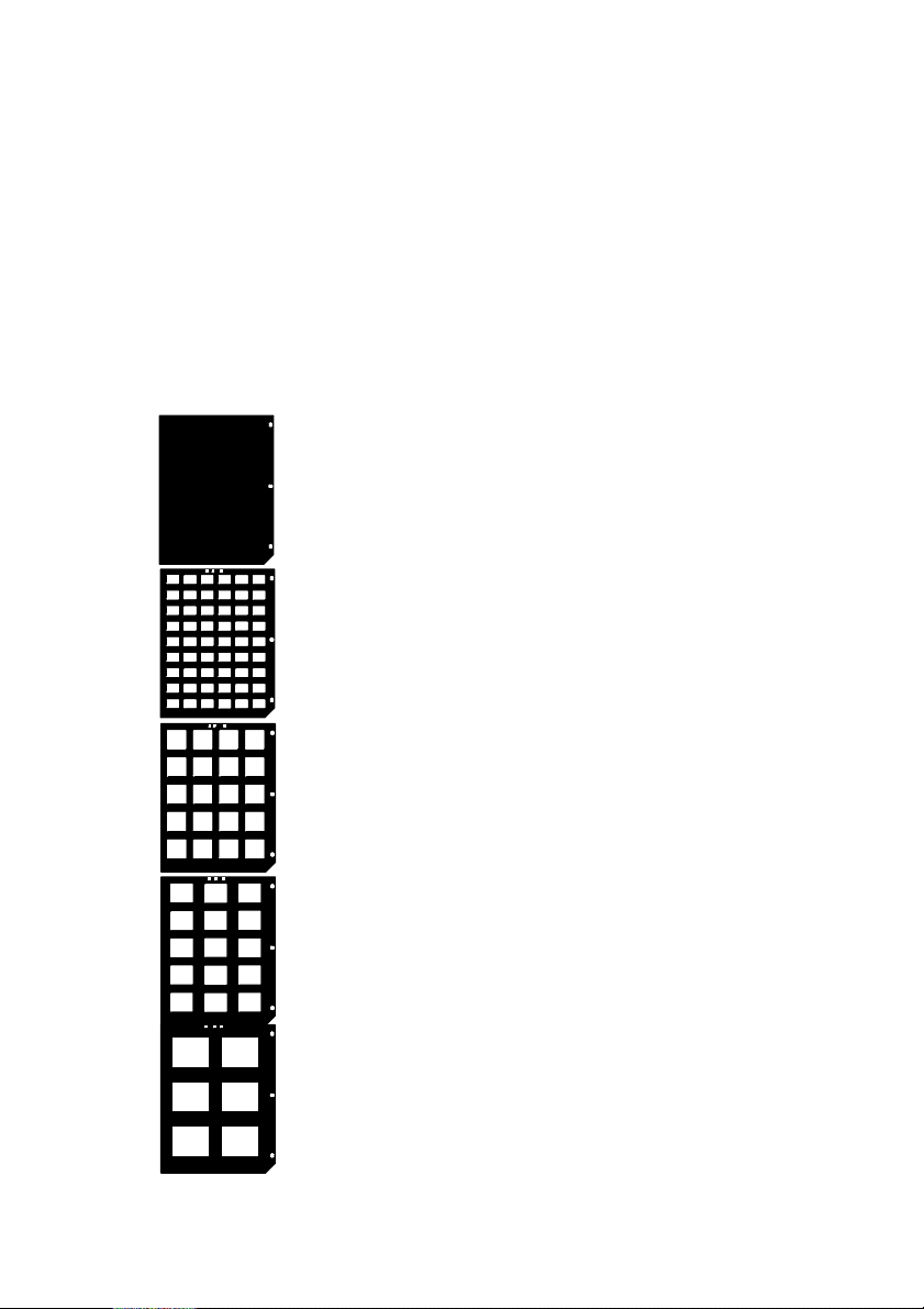
Passe-partouts are used for the simple mounting
of standard originals. The use of passepartouts
avoids stray light.They consist of black foil with
punched cut-outs.
0
There are 5 different passepartouts
Universal passepartout
24 x 36 mm, 54 cut-outs
6 cm x 6 cm, 20 cut-outs
6 cm x 7 cm, 15 cut-outs
4" x 5", 6 cut-outs
Nexscan F 4100/F 4200 – Operation 5– 1
Page 74
Accessories
Slide Tray
Register Pin Row
ABC
35 framed 24 x 36 mm small image
slides can be placed into this slide tray
(working with the slide tray – refer to
Chapter 4).
The register pin row is used for the trueto-register mounting of Copix originals
(color separations). It is secured to the
light table and the register strips can
subsequently be inserted and the
separation film glued into place.
The register pin row does not need to be
used for punched films.
5– 2 Edition September 2000
Page 75
ABC
Register Strip
Copix Tray
Accessories
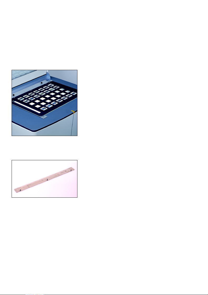
These strips are used as an aid for the
true-to register mounting of Copix
originals (color separations). It is
inserted into the register strip using the
Bacher punching system, the original
must then be glued onto the strip. The
strip with the original is subsequently
inserted into the scanner.
The Copix tray is used to weight the
originals in the scanner so that they lie
flat on the glass surface.
Nexscan F 4100/F 4200 – Operation 5– 3
Page 76

Page 77

ABC
6 Service and Maintenance
Notes on Care and Maintenance
When carrying out work, the user must adhere to
the stipulated work procedures described in the
operating instructions under all circumstances.
Warning: The unauthorized opening of housing
parts, not expressly described in the operating
3
instructions and improper repairs can lead to
considerable danger for the user.
Service work may only be carried out by persons
authorized by Heidelberg. The respective accident
prevention regulations must be observed at all
times.
Service and Maintenance
Nexscan F 4100/F 4200 – Operation 6– 1
Page 78
Service and Maintenance
Fluorescent Lamps
Attention: To ensure that the fluorescent lamps
function properly, the lamps are only switched
1
OFF when the scanning mode is changed
(reflective/transparent) or when no scanning has
taken place for a longer period of time.
If the lamps for scanning are no longer able to
illuminate sufficiently or are defective, the
corresponding fluorescent lamp must be replaced.
It is imperative that you only use clean fluorescent
lamps. If necessary, clean the lamp before
installation. Finger prints should likewise be
avoided as the grease can reduce the length of
operation.
ABC
11 watt fluorescent lamps are used for
the illumination of reflection or
transparent originals in the Nexscan
F 4100/F 4200.
The 11 watt fluorescent lamp is likewise
used for the illumination of originals in
the scanner.
Lamp used:
Osram FM 11W/860 Lumilux Tageslicht
6– 2 Edition September 2000
Page 79
ABC
Lamp Change for Reflection Scanning
1. Switch off the device.
Warning:
3
Pull out the power plug.
The ends of the fluorescent lamps can heat up to
100 °C when switched on.
2. Open the scanner lid.
3. Loosen the two slotted screws at the
front and the slotted screw at the rear
right for the glass plate in the scanner.
Remove the three mounting posts in
which the screws are located. The
mounting post at the rear left does not
have to be loosened.
Service and Maintenance
Removed
mounting
post
Nexscan F 4100/F 4200 – Operation 6– 3
4. Remove the glass plate.
Carefully remove the glass plate by
putting your fingers into the cutouts for
the front mounting post and raising the
glass plate.
5. Remove the black protective profile for
the fluorescent lamps. To do this, use
your fingers to press the snap-in clips
inwards through the round openings.
The fluorescent lamps are now
accessible.
Page 80
Service and Maintenance
Note: It is imperative that you only use clean
2
fluorescent lamps. If necessary, clean the lamp
before installation. Finger prints should likewise
be avoided as the grease can reduce the length of
operation.
7. Place the new fluorescent lamp into the mounting
post in such a way that it makes good contact.
ABC
6. Lift the defective fluorescent lamp out of
its mounting post.
8. Latch the black protective profile into the lamp
carrier.
9. Carefully reinsert the glass pane. Carefully slide
the pane against the stop pins to the rear and left.
Screw the 3 mounting posts into place. When
doing so make absolutely certain that the
mounting posts are inserted the right way round
to ensure that the glass pane does not break when
the screws are tightened.
10. Reconnect the device and switch it on.
6– 4 Edition September 2000
Page 81
ABC
Service and Maintenance
Lamp Change for Transparency Scanning
1. Switch off the device.
Warning:
3
Pull out the power plug.
The ends of the fluorescent lamps can heat up to
100 °C when switched on.
2. Open the scanner lid.
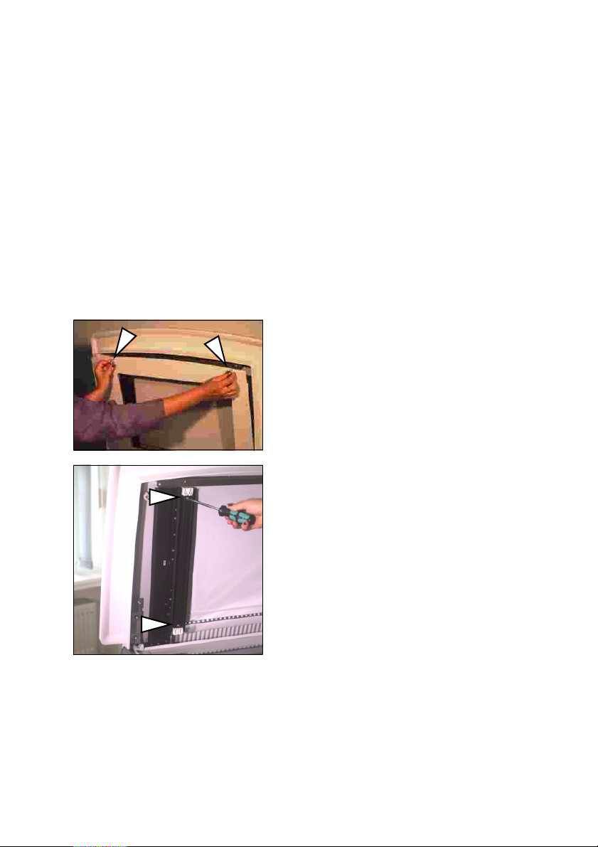
3. Loosen both knurled screws in the cover.
4. Carefully fold the plate with the glass
pane downwards.
5. Remove the two slotted screws for the
black reflection profile of the fluorescent
lamps. Remove the reflection profile. The
fluorescent lamps are now accessible.
Nexscan F 4100/F 4200 – Operation 6– 5
Page 82
Service and Maintenance
1
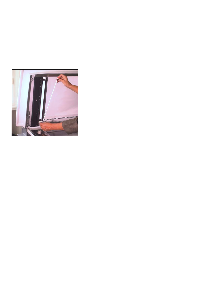
Note: It is imperative that you only use clean
2
fluorescent lamps. If necessary, clean the lamp
before installation. Finger prints should likewise
be avoided as the grease can reduce the length of
operation.
ABC
Attention: Ensure not to damage the
white reflection area behind the lamps.
You may not clean it or touch it with
other objects, e.g. finger nails or rings.
6. Lift the defective fluorescent lamp out of
its mounting post.
7. Place the new fluorescent lamp into the mounting
post in such a way that it makes good contact.
8. Screw the reflection profile back into place and
secure it in the inner part of the lid.
9. Reconnect the device and switch it on.
6– 6 Edition September 2000
Page 83
ABC
Service and Maintenance
Lamp Change for the Illumination of Originals
1. Switch off the device.
Warning:
3
Pull out the power plug.
The ends of the fluorescent lamps can heat up to
100 °C when switched on.
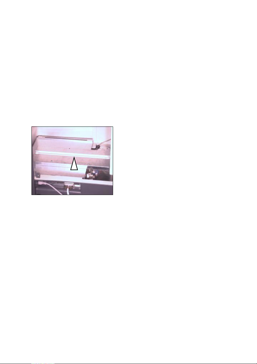
2. Loosen the 4 screws for the back panel
located at the rear of the device.
3. Remove the back panel.
4. Lift the defective fluorescent lamp out of
its mounting post.
Note: It is imperative that you only use clean
2
Nexscan F 4100/F 4200 – Operation 6– 7
fluorescent lamps. If necessary, clean the lamp
before installation. Finger prints should likewise
be avoided as the grease can reduce the length of
operation.
5. Place the new fluorescent lamp into the mounting
post in such a way that it makes good contact.
6. Screw the back panel back onto the device.
7. Reconnect the device and switch it on.
Page 84
Service and Maintenance
Replacing the Glass Plate
If the glass plate in your scanner is scratched or
broken, you can replace it yourself. Order No. for
the glass plate: 05355036
When reinstalling, proceed as follows:
1. Switch off the device.
Warning:
3
Pull out the power plug.
The ends of the fluorescent lamps can heat up to
100 °C when switched on.
ABC
2. Open the scanner lid.
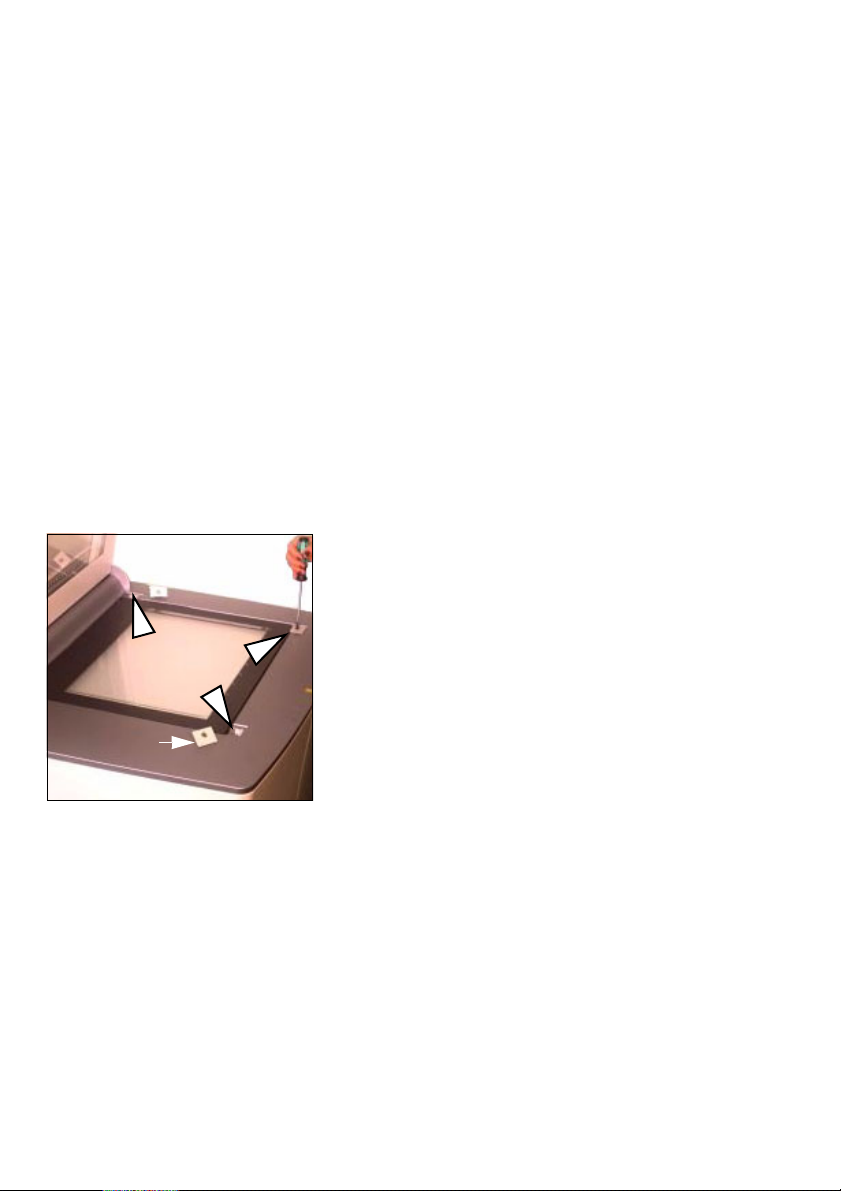
3. Loosen the two slotted screws at the
front and the slotted screw at the rear
right for the glass plate in the scanner.
Remove the three mounting posts in
which the screws are located. The
mounting post at the rear left does not
have to be loosened.
Removed
mounting
post
6– 8 Edition September 2000
4. Remove the glass plate.
Carefully remove the glass plate by
putting your fingers into the cutouts for
the front mounting post and raising the
glass plate.
5. Carefully insert the new glass pane.
Carefully slide the pane against the stop
pins to the rear and left. Screw the
3 mounting posts back into place. When
doing so make absolutely certain that
the mounting posts are inserted the right
way round to ensure that the glass pane
does not break when the screws are
tightened.
Page 85

ABC
6. Reconnect the device and switch it on.
7. Carry out a basic level adjustment (Siehe
Seite 4– 17).
Cleaning the Nexscan F 4100/F 4200
Attention: Isolate the device completely from the
power supply by pulling out the mains connection
1
plug before cleaning with a damp cloth!
Pollutants
When using cleaning agents or lubricants, pay
attention to manufacturer's instructions and
national regulations as well as safety data sheets.
Clean the surfaces of the device with a dry cloth.
If the device is very dirty, clean with a damp cloth
which has been dipped in dish-washing liquid and
well wrung.
Service and Maintenance
Make sure that no liquid enters the device. Keep
the outlets of the device dry.
Never use abrasive cleaning agents or solvents!
Nexscan F 4100/F 4200 – Operation 6– 9
Page 86
Service and Maintenance
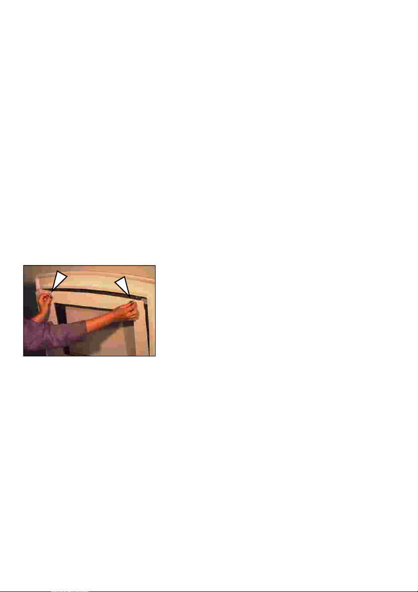
Removing Dust in the Lid
Dust may possibly need to be removed from the
glass plate in the lid to maintain constant good
quality for transparency scanning.
Proceed as follows:
1. Switch off the device.
Warning:
3
Pull out the power plug.
The ends of the fluorescent lamps can heat up to
100 °C when switched on.
ABC
2. Open the scanner lid.
3. Loosen both knurled screws in the cover.
4. Carefully fold the plate with the glass
pane downwards.
5. Wipe the glass pane with a lint-free cloth.
6. Screw the inner part of the lid into place.
7. Reconnect the device and switch it on.
6– 10 Edition September 2000
Page 87
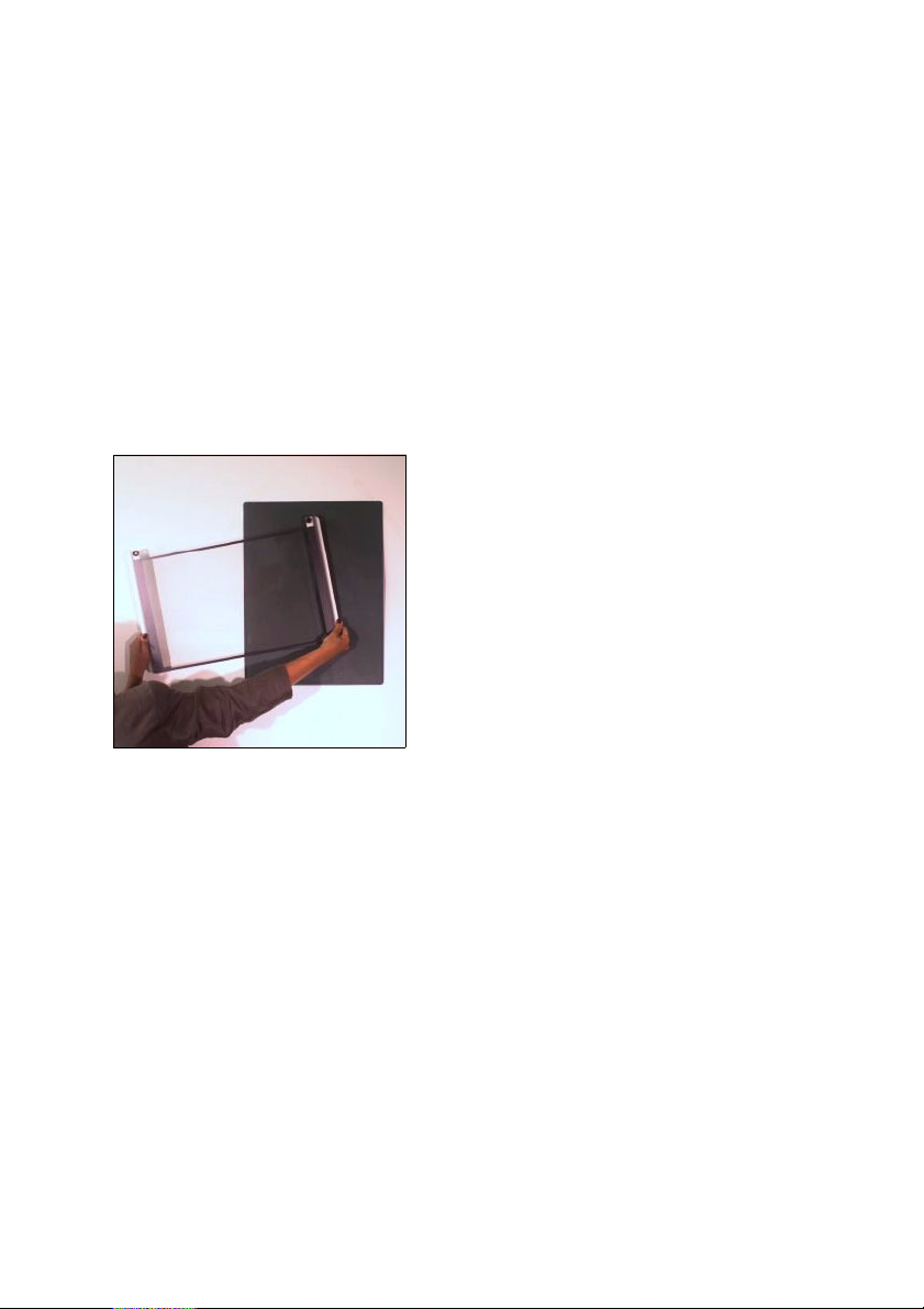
ABC
Service and Maintenance
Cleaning the Glass Surface/Universal Tray
In order to obtain optimum scanning results, the
glass surfaces (and trays) must be handled
carefully and cleaned at regular intervals.
Attention: Ensure that no liquids enter the interior
1
Checking the Cleanliness of the Tray
of the device!
Hold the tray against a dark background
and then against a light background.
Holding the glass plate up against the
light, look at it from different angles and
distances to determine whether the glass
is dirty or not and on which surface.
Cleaning Preparation
Avoid electrostatic charges (e.g. by grounding).
Put on lint-free gloves.
Put the tray down on a pad (with the dirty side up).
Maintain a small distance between the tray and
the pad by resting the tray on spacers.
Note: Both sides of the tray have an anti-Newton
coating – do not scrape or scratch.
2
Nexscan F 4100/F 4200 – Operation 6– 11
Page 88
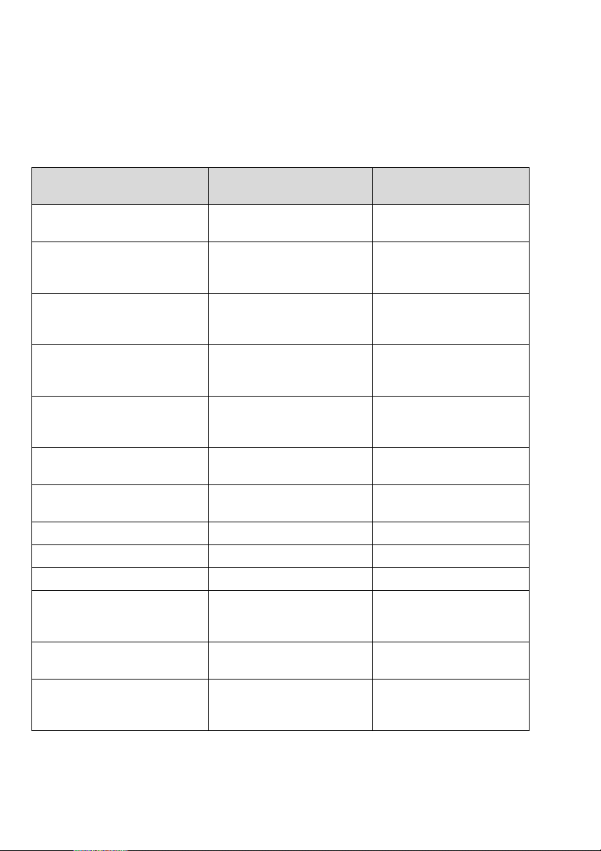
Service and Maintenance
The following table will help you when selecting
cleaning agents:
ABC
Cleaning Material/
Equipment
Dark pads
(approx. 5OO mm x 5OO mm)
Lint-free gloves Polyester gloves,
Absorbent, lint-free cloths Kleenex Professional
Oil-free compressed air Compressed air 67,
Antistatic brush, grounded Antistatic brush,
Antistatic unit Antistatic unit 1212,
Ethanol,
spectroscopically pure
Foam cleaner Specialist dealer
Acetic acid Specialist dealer
Acetone Specialist dealer
Foam cleaner Messrs. Röbel u. Fiedler,
Standard domestic cleaners
without silicone additives
Cleaning cloth Etuis-Duggert GmbH
Name / Supplier (example) Remarks
Black cloth
MAB 02, Messrs. Basan
FRANKFURT
Wipes, Code 7107,
Kimberly Clark
Messrs. Kontakt Chemie,
RASTATT
CW 101/SW 141,
Messrs. Kinetronics
Messrs. Kinetronics
Chemical suppliers
Chemische Fabrik GmbH,
77955 Ettenheim/Germany
Local specialist dealer
Dobelstraße 6
D-73087 Bad Boll
Order No. 02336154
Order No. 02065436
Cleaning cloth, 7919-160
KaneboUni, 19x19 cm
loose
6– 12 Edition September 2000
Page 89
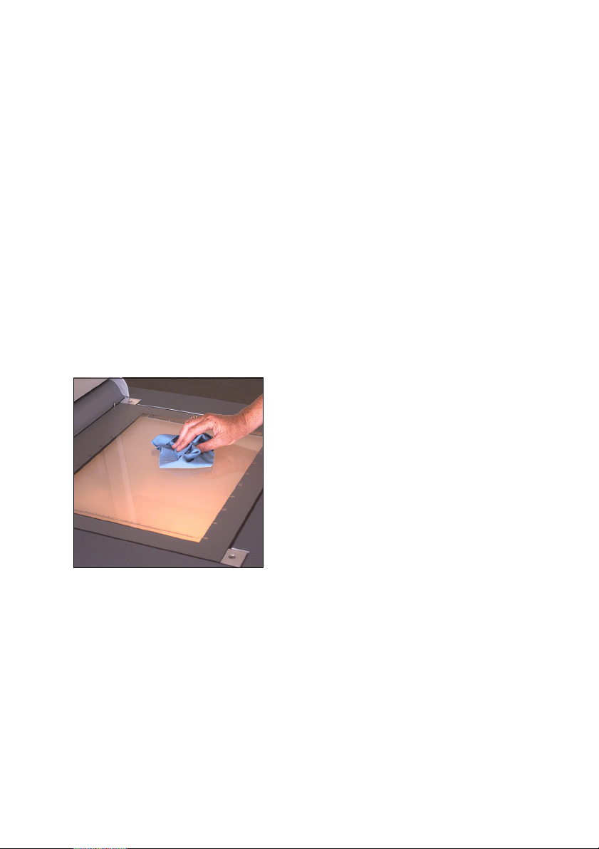
ABC
3
3
Liquids
Service and Maintenance
Warning: Cleaning agents such as ethanol and
acetone are flammable, therefore:
0
Do not smoke during cleaning
0
Avoid electrostatic discharges
0
Only use cleaning agents drop by drop to
exclude the danger of deflagration
Warning: Before using cleaning agents, be sure to
observe the manufacturer's notes and the current
safety data sheets from the relevant
manufacturer.
Dab the area using a lint-free cloth (then
continue cleaning with glass or foam
cleaner).
Nexscan F 4100/F 4200 – Operation 6– 13
Page 90
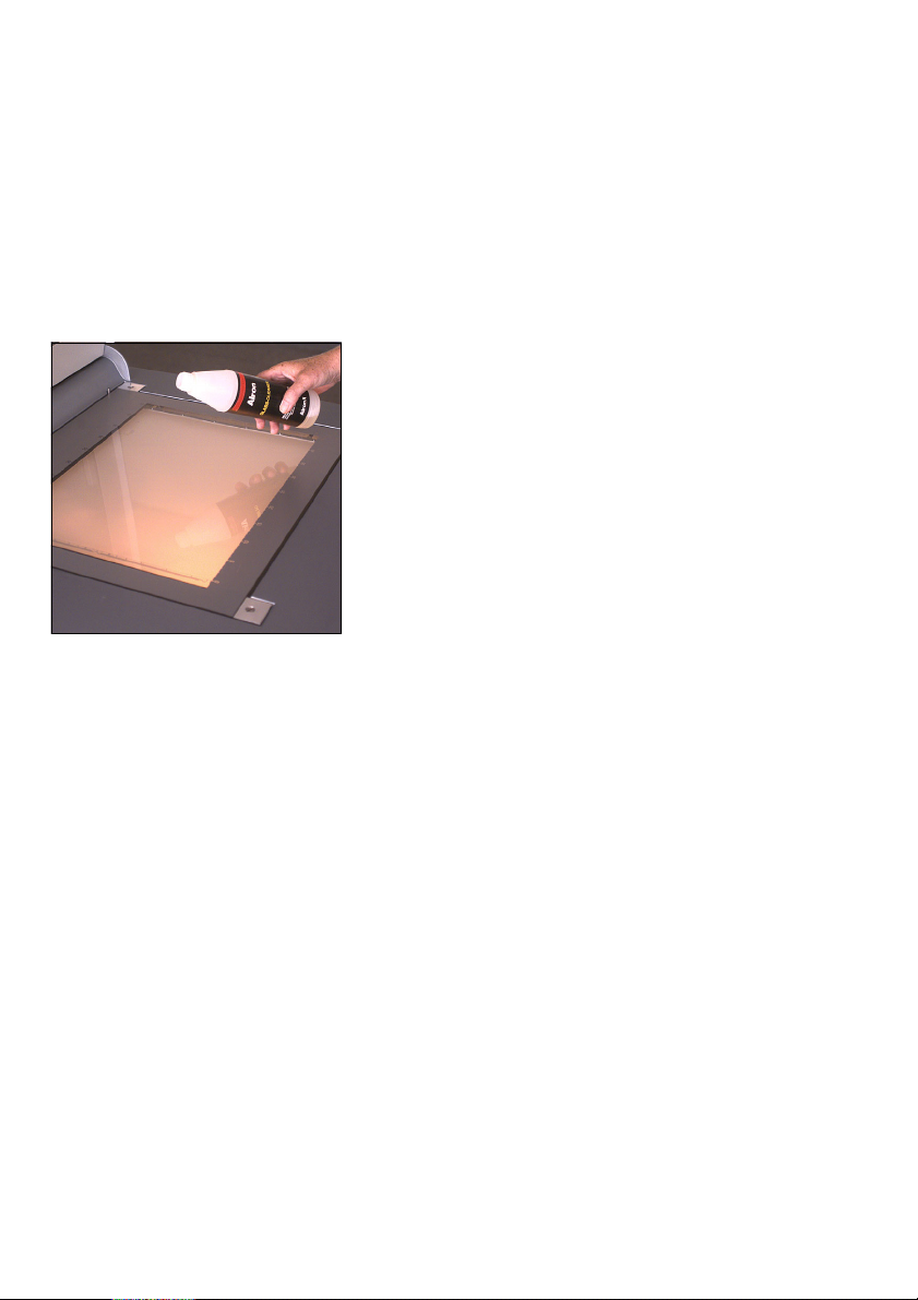
Service and Maintenance
Dry Finger Prints; Adhesive Tape Residue, Smudges
(Except for Acetone Rings, Refer to Cleaning with Acetone).
Attention: Ensure that no liquids enter
the interior of the device!
ABC
1
0
Apply or spray the glass or foam
cleaner onto the glass surface.
For foam cleaning: Shake the foam
cleaner before use, spray it onto the
glass plate and apply it using a cloth.
Wait until the foam has had time to
work.
0
Using a lint-free cloth, remove the
foam or glass cleaner by wiping the
cloth in the same direction applying a
little bit of pressure. Use several
cloths if necessary.
0
Subsequently clean with ethanol.
6– 14 Edition September 2000
Page 91

ABC
Streaks, Damp Areas, Fresh Finger Prints
Cleaning with Ethanol:
Service and Maintenance
Refer to safety instructions on Seite 6–13
Attention: Ensure that no liquids enter the interior
1
Dust (To Be Removed Directly Before Scanning)
of the device!
Spray the entire surface to be cleaned with
ethanol (cover the opposite surface).
Moisten a lint-free cloth with a small amount of
ethanol and remove the liquid by wiping the cloth
in the same direction applying a little bit of
pressure. A thin film of alcohol (which will
evaporate) should be left on the surface.
Note: Cleaning is successful if the film of alcohol
does not form any drops and evaporates without
2
leaving any streaks. Repeat the procedure if
necessary!
Remove dust from the glass plate using a
grounded antistatic brush and oil-free
compressed air.
Note: Do not blow the compressed air over the
glass plate in short blasts as this would cause
2
condensation. Use a steady stream of air over the
plate!
.
The tray can be driven through an antistatic
device beforehand to avoid static charge.
Nexscan F 4100/F 4200 – Operation 6– 15
Page 92

Service and Maintenance
Stains That Could Not Be Removed Following The Previous Procedures
Cleaning with Acetone:
Note: Cleaning with acetone should only be
performed when cleaning with the other agents
2
was unsuccessful.
ABC
1
Refer to safety instructions on Seite 6– 13
First of all sprinkle acetone over the stain and its
surrounding area.
Attention: Never dampen the frame of the tray!
Ensure that no liquids enter the interior of the
device!
Wait until the acetone has had time to work.
Remove the liquid using a lint-free cloth. (The
acetone should not have evaporated. Apply again,
if necessary.)
Repeat the procedure, but using diluted acetic
acid (25% concentrate) instead of acetone.
Repeat the procedure using acetone and diluted
acetic acid alternately until the stain has been
removed. (Always use acetic acid solution at the
end to prevent acetone rings!)
Then clean using a foam cleaner directly
afterwards.
.
6– 16 Edition September 2000
Page 93
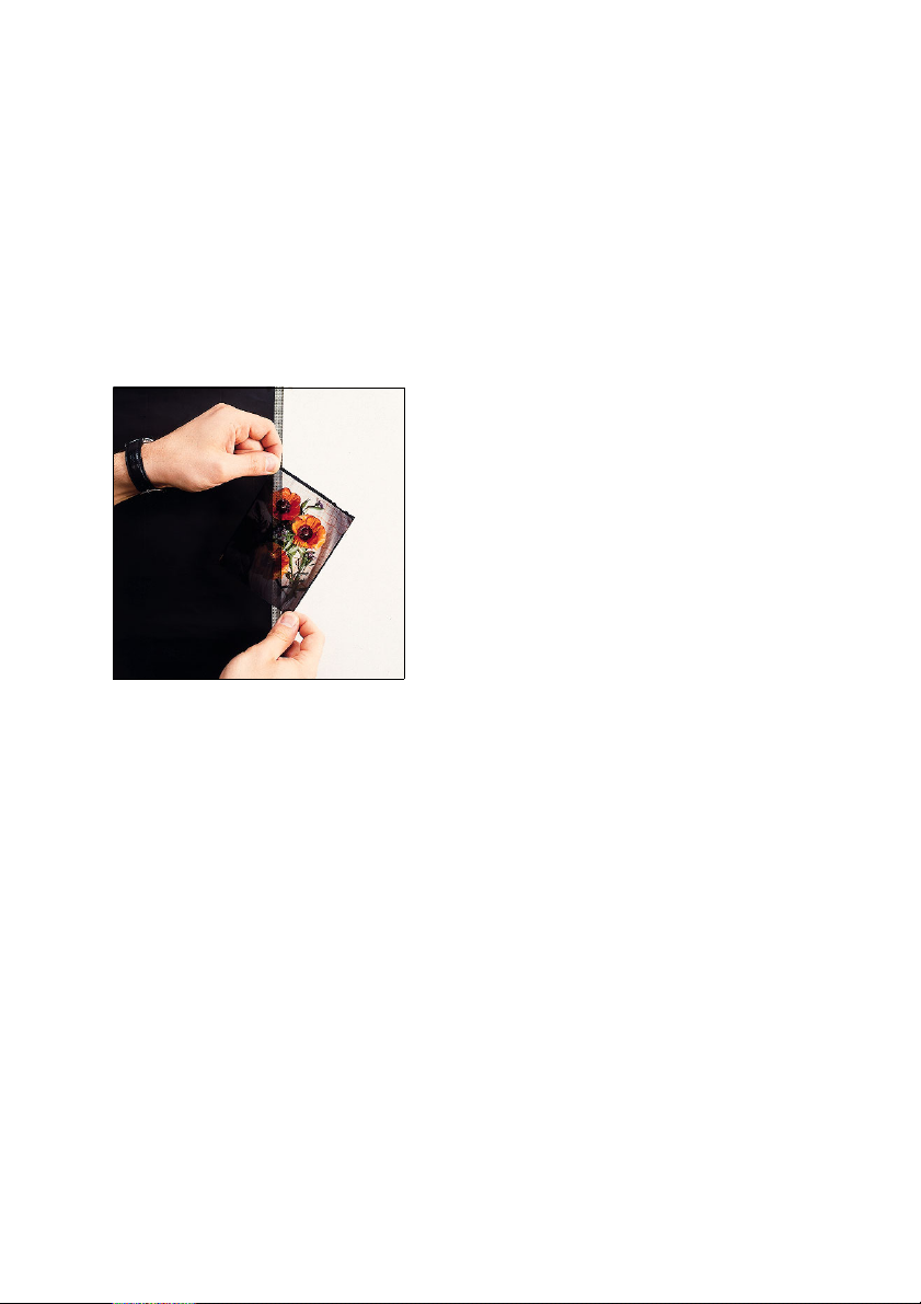
ABC
Cleaning Originals
In order to obtain optimal scanning results, the
originals must also be cleaned and looked after as
required.
Checking the Cleanliness of the Original
Hold transparency originals against a
dark background and then in front of and
against a light background and observe
them from different angles and
distances. Determine whether the
original is dirty or not, and if so, the
nature of the stain.
Observe reflection originals in front of a
light background from different angles
and distances. Determine whether the
original is dirty or not, and if so, the
nature of the stain.
Service and Maintenance
Preparing the Originals for Cleaning
Avoid electrostatic charges (e.g. by grounding).
Switch on the antistatic device. Wait for approx.
one minute and then move a pin through the
brush in order to remove the dust.
Put on lint-free gloves.
Remove the dust from the original (e.g. by moving
it through the antistatic device and brushing it).
Place the original flat on a clean, smooth and even
plate with the dirty side up and secure it, if
necessary.
Nexscan F 4100/F 4200 – Operation 6– 17
Page 94
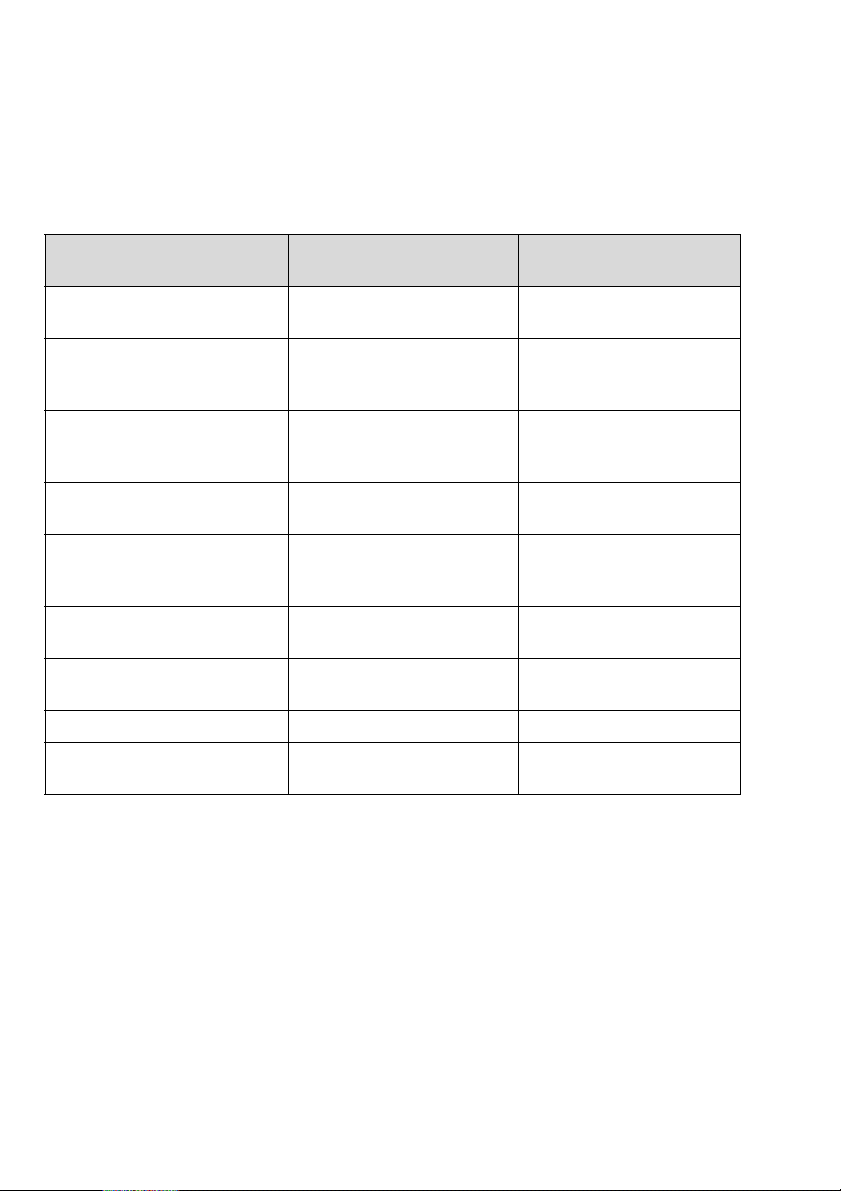
Service and Maintenance
3
The following table will help you when selecting
cleaning agents:
ABC
Cleaning Material/
Equipment
Dark pads
(approx. 5OO mm x 5OO mm)
Lint-free gloves Polyester gloves, MAB 02,
Absorbent, lint-free cloths Kleenex Professional
Oil-free compressed air Compressed air 67, Messrs.
Antistatic brush, grounded Antistatic brush,
Antistatic unit Antistatic unit 1212,
Ethanol,
spectroscopically pure
Adhesive roller Nagaoka Rolling Cleaner
Bent forceps, 90 offset,
metal or plastic
Name / Supplier (example) Remarks
Black cloth
Messrs. Basan
FRANKFURT
Wipes, Code 7107,
Kimberly Clark
Kontakt Chemie, RASTATT
CW 101/SW 141,
Messrs. Kinetronics
Messrs. Kinetronics
Chemical suppliers
Laboratory suppliers Order No. 04160770
Warning: Cleaning agents such as ethanol are
flammable, therefore:
0
Do not smoke during cleaning
0
Avoid electrostatic discharges
0
Only use cleaning agents drop by drop to
exclude the danger of deflagration
Order No. 02336154
Order No. 02065436
6– 18 Edition September 2000
Page 95
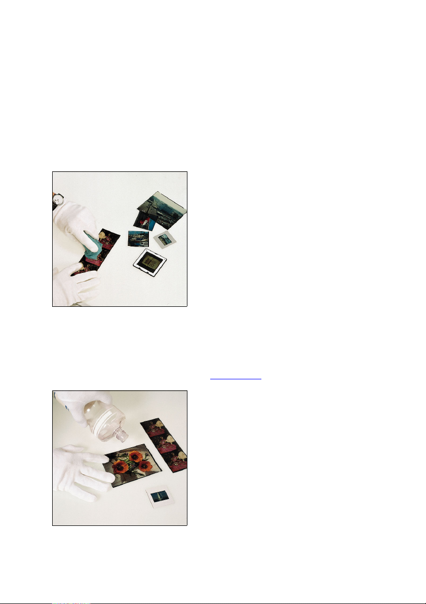
ABC
3
Warning: Before using cleaning agents, be sure to
observe the manufacturer's notes and the current
safety data sheets from the relevant
manufacturer.
Liquids
Dab the area using a lint-free cloth (then
clean with ethanol).
Dry Finger Prints; Adhesive Tape Residue, Dry Smudges
0
Cleaning with ethanol
Service and Maintenance
Refer to safety instructions on
Seite 6–18
Spray or sprinkle the entire surface to be
cleaned with ethanol (use sparingly).
Nexscan F 4100/F 4200 – Operation 6– 19
.
Page 96
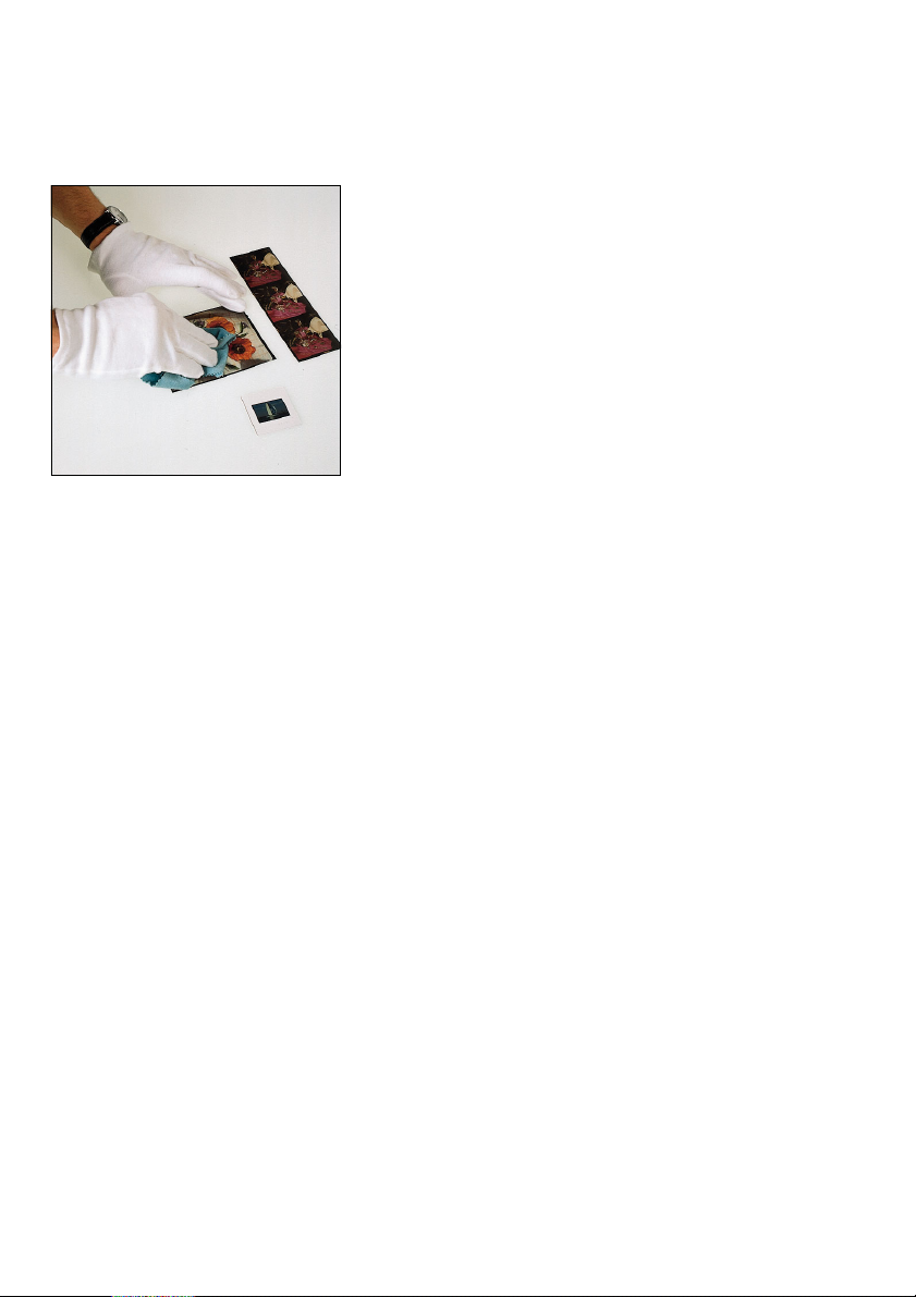
Service and Maintenance
ABC
0
Wipe off the ethanol
Moisten a lint-free cloth with a small
amount of ethanol and remove the liquid
by wiping the cloth in the same direction
applying a little bit of pressure.
A thin film of alcohol (which will
evaporate) should be left on the surface.
Note: Cleaning is successful if
the film of alcohol does not
2
form any drops and evaporates
without leaving any streaks.
Repeat the procedure if
necessary!
If you also wish to clean the other side of
the original, lift the original and wipe the
glass plate dry. Then clean as described
above.
(Subsequently clean off the dust)
Dust
Carefully pull the original through the antistatic
device.
Remove dust from the original using a grounded
antistatic brush and oil-free compressed air.
Note: Do not blow the compressed air over the
original in short blasts as this would cause
2
condensation. Use a steady stream of air over the
original!
6– 20 Edition September 2000
Page 97

ABC
Stains That Could Not Be Removed By Dabbing And Cleaning With Ethanol
Cleaning with Film Cleaner:
Service and Maintenance
Refer to safety instructions on Seite 6–18
Depending on the type of original, other cleaning
agents (e.g. solvents such as naphtha, film cleaner
and others) can be used in addition to ethanol.
Experiment for best results.
If you use other agents, you should always finish
off cleaning with ethanol.
Dust That Could Not Be Removed Following The Normal Procedure
Removing Dust with an Adhesive Roller:
Place the original flat on a clean, smooth and even
plate with the surface to be cleaned facing up.
Continuously roll the adhesive roller over it.
Note: The original is electro-statically charged.
The roller must be dry before using it (clean it
2
with water).
Raise the original.
Then carry out a normal clean to remove dust.
.
Nexscan F 4100/F 4200 – Operation 6– 21
Page 98

Service and Maintenance
General Remarks on Maintenance
Avoid humidity, dust and electrostatic charges, if
possible.
Store the trays, cassettes and originals in a dry
place which does not become very dusty.
Remove stains immediately. Do not wait until the
stains have dried!
Provide sufficient ventilation when performing
any cleaning procedures.
Do not allow the cleaning liquids to run over the
surface to be cleaned.
Only mount dry, clean originals. If possible, avoid
using Anti Newton oil.
When cleaning, avoid using:
- Silicone-based domestic cleaners
- Tap water (this leaves mineral deposits)
- Antistatic cloths (this leaves a residue)
- Methylated spirits: Methylated spirit
ABC
PCBs and semi-conductor modules should remain
in their original packing as long as possible. When
shipped or stored, use either the original or
adequate protective packing.
6– 22 Edition September 2000
Page 99
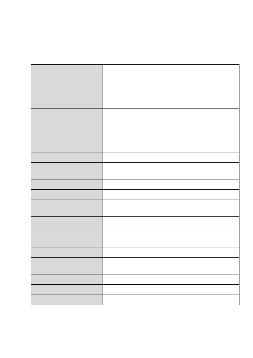
ABC
Technical Data and Accessories
7 Technical Data and Accessories
Technical Data
Scanning mode CCD system
3 x 8000 CCD color lines for RGB and
1 x 12000 b/w CCD lines for Copy Dot (F4200 only)
Detail contrast (USM) Digital (program controlled)
Focus Computer controlled, autofocus
Max. effective format Transparency/reflection: 315 x 457 mm, 12.4 x 18
Copix: 315 x 457 mm, 12.4 x 18
Optical resolution 645 - 5080 dpi for the entire scanning area
902 - 7040 dpi for Copy Dot (F4200 only)
Interpolated resolutions 10,800 dpi
Scale range 20% - 2500%
Max. thickness of
originals
Standard interface SCSI (image data and communication)
SCSI address 5 (preset)
Dimensions
(width x height x depth)
Power supply 100V - 120V/200V - 240V ± 10% single phase
Frequency 50/60 Hz
Rated current 2.0 A
Power consumption Approx. 500 W
Operating ambient
temperature
Air humidity 30 - 80% (non-condensing)
Operating weight Approx. 89 kg
Acoustic noise emission Below 55 dB (A)
Nexscan F 4100/F 4200 – Operation 7– 1
Transparency: 20 mm, reflection: unlimited
855 x 990 x 710 mm,
1,545 mm height with scanner lid open
18 to 28 °C
Page 100

Technical Data and Accessories
Accessories
Nexscan accessories: Order No.:
Mounting rail (placed in the scanner) 05392500
Passepartout basic set 05401615
Passepartout set Uni (10 items) 05401623
Passepartout set 24 x 36 mm (10 items) 05401658
Passepartout set 6 x 6 cm (10 items) 05401674
Passepartout set 6 x 7 cm (10 items) 05401704
Passepartout set 4" x 5" (10 items) 05394201
Fluorescent lamp, 230V/11W,
Color temperature 6000K
Register pin row Copix, Bacher, (metal) 05401771
ABC
Universal tray 05455014
Copix Tray 05454387
05226112
Slide tray 05401607
Register pin row Copix, Bacher (plastic)
(12 items)
Glass plate for scanner 05355036
Tweezers 04160770
Rubber blower 00346608
Anti-Newton spray 00129100
Antistatic cloth 00057606
Mounting foil 03004570
7– 2 Edition September 2000
05392683
 Loading...