

Heatworks Model 1 Installation And User Manual
www.myheatworks.com
INSTALLATION & USER
MANUAL

CONTENTS
www.myheatworks.com
1
2
3
4
5
7
11
13
14
15
1. Important Safety Information
2. How to Use this Manual
Included in the Box
Required for Installation
3. Heatworks MODEL 1 Diagram
4. Installing the Mounting Brackets
5. Plumbing Installation
Installing Units in Parallel
6. Electrical Installation
Setting the Amperage
Adjusting the Temperature
7. Electrician’s White Paper
8. MODEL 1 Specifications
9. Troubleshooting
10. Heatworks MODEL 1 Limited Warranty
Warranty Registration
11. Return Process
17
CAUTION: Breaker must remain off until installation is complete.

PLEASE READ THESE INSTRUCTIONS
THOROUGHLY AND COMPLETELY
PRIOR TO INSTALLATION AND USE.
FAILURE TO DO SO COULD RESULT IN
PROPERTY DAMAGE, SERIOUS INJURY,
OR DEATH. IMPROPER INSTALLATION
OR USE WILL VOID YOUR WARRANTY.
www.myheatworks.com
1
TURN OFF CIRCUIT BREAKER AND WATER SUPPLY
BEFORE INSTALLING THE MODEL 1.
SERIOUS BODILY INJURY OR DEATH MAY OCCUR IF
YOU IGNORE THIS WARNING.
Shut off all power to the unit directly at the breaker
box prior to installing or inspecting your Heatworks
MODEL 1.
The Heatworks MODEL 1 must be installed by a licensed
electrician and licensed plumber in accordance with all
national, state, provincial, and local electrical and
plumbing codes.
This Heatworks MODEL 1 was tested before leaving the
factory. As a result, there may be a small amount of
residual water in the MODEL 1.
CAUTION: Breaker must remain off until installation is complete.
IMPORTANT SAFETY INFORMATION 1
CAUTION: Breaker must remain off until installation is complete.
Check our website,
www.myheatworks.com for the latest
version of the Installation & User Manual.
REQUIRED FOR INSTALLATION
Designated 110-250 volts, 15-48 amp circuit installed
by a licensed electrician.
Water supply using ¾” or 22mm push-fit connectors
Flat mounting surface (ie: a wall) – DO NOT SECURE
THE MODEL 1 TO PIPING
RECOMMENDED FOR INSTALLATION
Flexible water heater connection hoses
ADDITIONAL HELPFUL MATERIALS
Drywall anchors, plywood, or stud finder to ensure
brackets will support the MODEL 1
Level to ensure mounting brackets are level before
MODEL 1 is secured with zip ties
YOU ARE NOW READY TO BEGIN INSTALLING YOUR
HEATWORKS MODEL 1
Please continue to page 3
HOW TO USE THIS MANUAL2
www.myheatworks.com
2
Please proceed with installation of your MODEL 1 by
following the steps in the sequence they are presented.
Throughout this manual, we have highlighted certain
points that require special attention. These points are
indicated by the three BOLDED categories below:
“IMPORTANT” Commonly missed step in installation.
“CAUTION” Negligence of this step could result in
damage to your MODEL 1 or personal injury.
“HEATWORKS RECOMMENDS” The user or installer
should be aware of these additional notes and benefits.
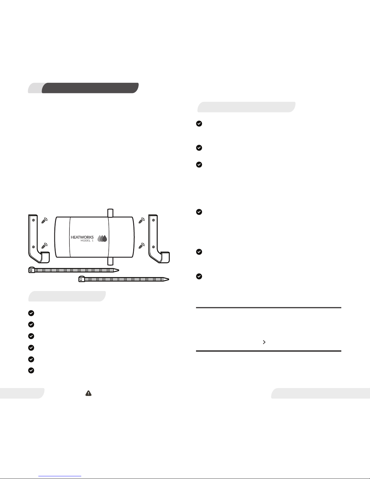
INCLUDED IN THE BOX:
1 Heatworks MODEL 1 water heater
1 Heatworks MODEL 1 Installation and User Manual
2 Mounting Brackets
4 Mounting Bracket Screws
2 Zip Ties
1 Showerhead – Our Gift to You
CAUTION: Breaker must remain off until installation is complete.
HEATWORKS MODEL 1 DIAGRAM3
www.myheatworks.com
3
HEATWORKS RECOMMENDS: If your water comes from a
well, it is recommended you install a sand filter on the
main water line entering the house, from the well. There
is also a small filter screen inside the water inlet of the
Heatworks MODEL 1.
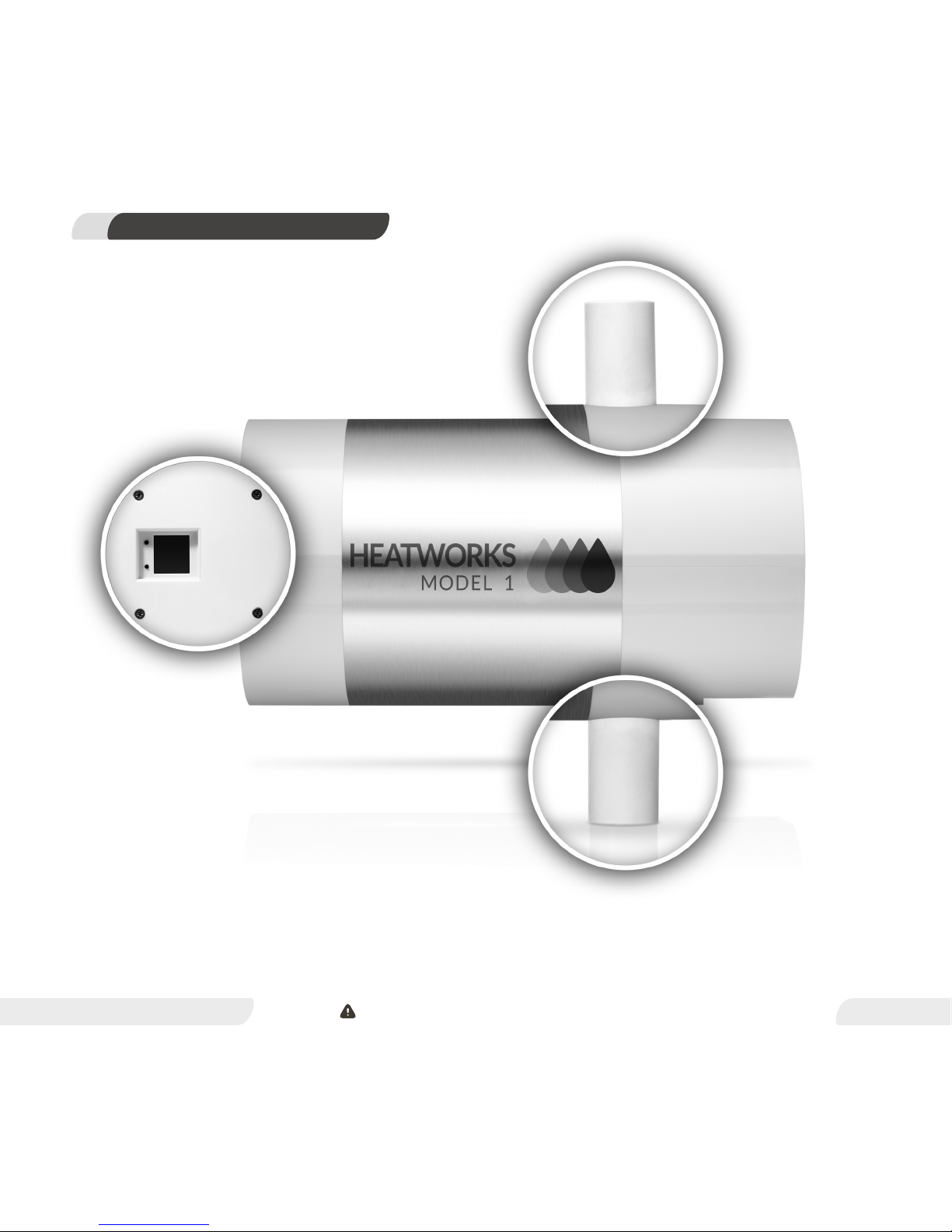
OUTLET/TOP
INLET / BOTTOM
CONTROL END
CAUTION: Breaker must remain off until installation is complete.

IMPORTANT: The Heatworks MODEL 1 must be oriented
horizontally.
The cold water inlet must be on the bottom of the
MODEL 1, and the outlet must be on the top. (Shown in
Heatworks MODEL 1 Diagram; page 3)
Do not use any other mounting method than the
brackets and zip ties provided.
STEPS
1) Position (2) mounting brackets approximately 6 inches
apart and level to support the weight of the MODEL 1,
which is approximately 15 pounds when full of water.
HEATWORKS RECOMMENDS: Dry wall anchors are
strongly recommended for installation, or drill directly
into studs. Do not attach to drywall without drywall
anchors.
2) Secure mounting brackets to a flat surface, such as a
wall, using mounting (4) bracket screws.
3) Place the MODEL 1 on the brackets. Check the position
and orientation to ensure the unit is level, with the inlet
on the bottom and the outlet on the top.
4) Thread (2) cable ties through the brackets, around the
MODEL 1.
YOU ARE NOW READY TO PROCEED TO PLUMBING
INSTALLATION
Please continue to page 5
INSTALLING THE MOUNTING BRACKETS 4
www.myheatworks.com
4
CAUTION: Breaker must remain off until installation is complete.
4) Connect the cold water supply line to the MODEL 1
inlet marked “inlet” on the bottom of the unit.
HEATWORKS RECOMMENDS: Install a manual shut-off
valve (ball valve) on the inlet side of the Heatworks
MODEL 1 to provide a convenient shut-off point.
5) Turn on the main water supply.
6) Purge all air from the water lines and MODEL 1 by
opening a hot water demand source (hot faucet, shower,
etc.). Allow water to run though the water heater for at
least 2 to 3 minutes. Water from faucet will not be hot at
this point.
PLUMBING INSTALLATION5
www.myheatworks.com
5
Follow all plumbing instructions carefully. This product
MUST be installed by a licensed plumber in accordance
with all applicable national, state, provincial, and local
plumbing codes.
STEPS
1) Flush the existing water lines to eliminate all plumbing
or plastic paste or residue caused by any previous
brazing or soldering.
2) Turn off the main water supply.
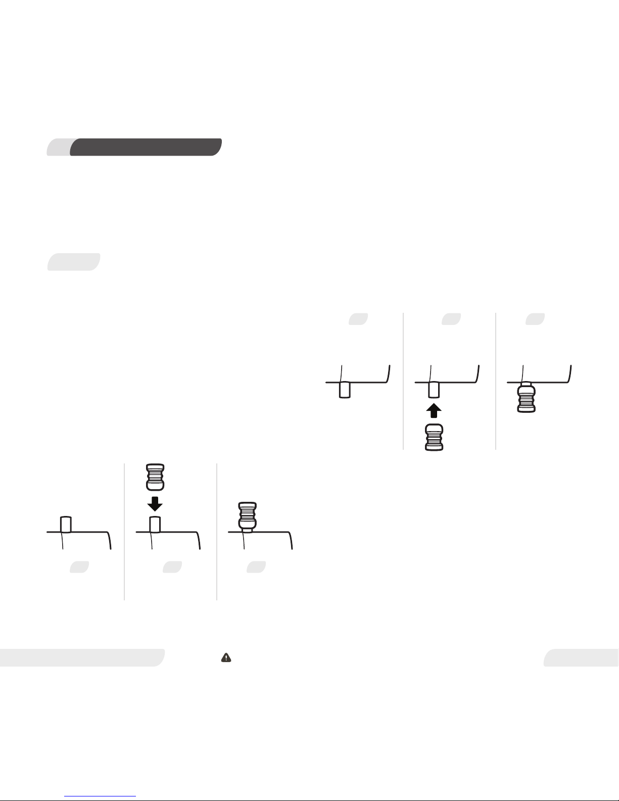
3) Connect the hot water line to the MODEL 1 outlet
marked “outlet” located on the top of the unit.
HEATWORKS RECOMMENDS: Use flexible water heater
hoses and push-fit fittings for ease of installation.
BEFORE
PUSH-FIT FITTING
PUSH-FIT
FITTING
INSTALLED
PUSH-FIT FITTING
1 2 3
OULET / TOP
INLET/BOTTOM
BEFORE
PUSH-FIT FITTING
PUSH-FIT
FITTING
INSTALLED
PUSH-FIT FITTING
1 2 3
CAUTION: Breaker must remain off until installation is complete.
Outlet
Inlet
Outlet
Inlet
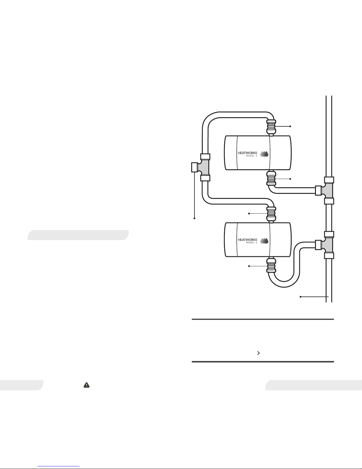
When installing multiple MODEL 1 units in the same
location with the purpose of having them support the
same hot water demand, please refer to the diagram to
the right.
In this installation configuration the cold water supply
line is split into two dedicated water lines, one line for
each MODEL 1 unit. The hot water lines then converge so
the outlet of each MODEL 1 unit supplies one hot water
line.
CAUTION: Serious damage to your Heatworks MODEL 1
can occur if all air is not purged from the water lines and
MODEL 1, any time air might be introduced into your
home water system.
7) Carefully inspect all connections and unions for leaks.
HEATWORKS RECOMMENDS: Since this product does
not use a storage tank, the use of a temperature
pressure relief valve (T&P) is not required for most
installations. However, a T&P valve may be required to
meet plumbing codes in your area.
CAUTION: The maximum recommended operating water
pressure for the Heatworks MODEL 1 is 100 PSI. Consult
your licensed plumber for specific information regarding
your water pressure.
INSTALLING UNITS IN PARALLEL
www.myheatworks.com
6
YOU ARE NOW READY TO PROCEED TO THE
ELECTRICAL INSTALLATION
Please continue to page 7
Cold Water Source
Hot Water
Outlet
UNITS INSTALLED IN PARALLEL
CAUTION: Breaker must remain off until installation is complete.

SERIOUS BODILY INJURY OR DEATH COULD OCCUR IF
YOU IGNORE THIS WARNING.
The Heatworks MODEL 1 must be installed by a licensed
electrician in accordance with all applicable national,
state, provincial, and local electrical codes. Under no
circumstances should the Heatworks MODEL 1 be
installed without first shutting off all power to the unit at
the fuse or breaker box.
STEPS
1) Prior to wiring your Heatworks MODEL 1, a licensed
electrician should consult the Electrician’s White Paper on
page 16.
2) Verify all wiring (wire gauge) and circuit protection
(breakers) comply with national and local electrical codes.
3) The MODEL 1 requires two power conductors and one
grounding conductor.
a) The line conductors can both be phase, or one line
may be phase and the other neutral. (split-phase
installation)
b) Connect the two power and one ground wires to
the MODEL 1.
4) The MODEL 1 auto senses voltage from 110-250 VAC
(50/60 Hz). No adjustment is needed to set voltage.
5) Verify water supply to the Heatworks MODEL 1 is
turned on, and MODEL 1 has been purged of air.
CAUTION: Serious damage to your Heatworks MODEL 1
can occur if all air is not purged from the water lines and
MODEL 1 any time air might be introduced into your
home water system.
ELECTRICAL INSTALLATION6
www.myheatworks.com
7
YOU ARE NOW READY TO SET THE MAXIMUM
AMPERAGE
Please continue to page 8
CAUTION: Breaker must remain off until installation is complete.
IMPORTANT: The factory default amperage draw is 15
Amperes. To maximize the amount of temperature rise,
be sure to program your desired amperage to your
specific hot water needs. Also, be sure that your MODEL
1 has been installed and wired to meet the amperage
requirements programmed.
SETTING THE AMPERAGE
www.myheatworks.com
8
STEPS
1) Turn on any hot water faucet.
2) Allow the water to run for 1 minute. Water will not be
hot.
3) Turn on power to the MODEL 1 by turning on the
associated breaker.
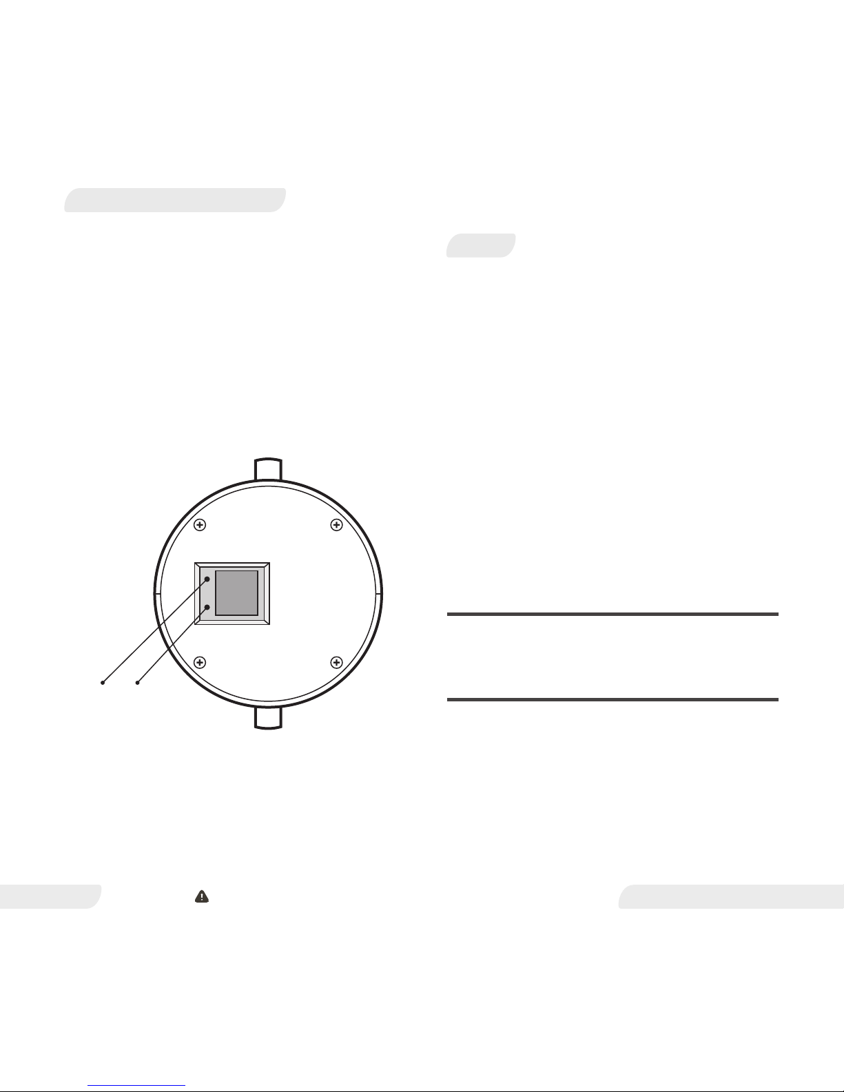
4) Press and hold both buttons beside the display screen
of the MODEL 1. (See diagram to the left).
5) Release ONLY the top button.
6) While continuing to hold the bottom button, press and
release the top button five times until the number “5”
appears. The display should start blinking.
IMPORTANT: If the top button is accidentally pressed
more than 5 times, press and release both buttons to
start over.
7) Release both buttons.
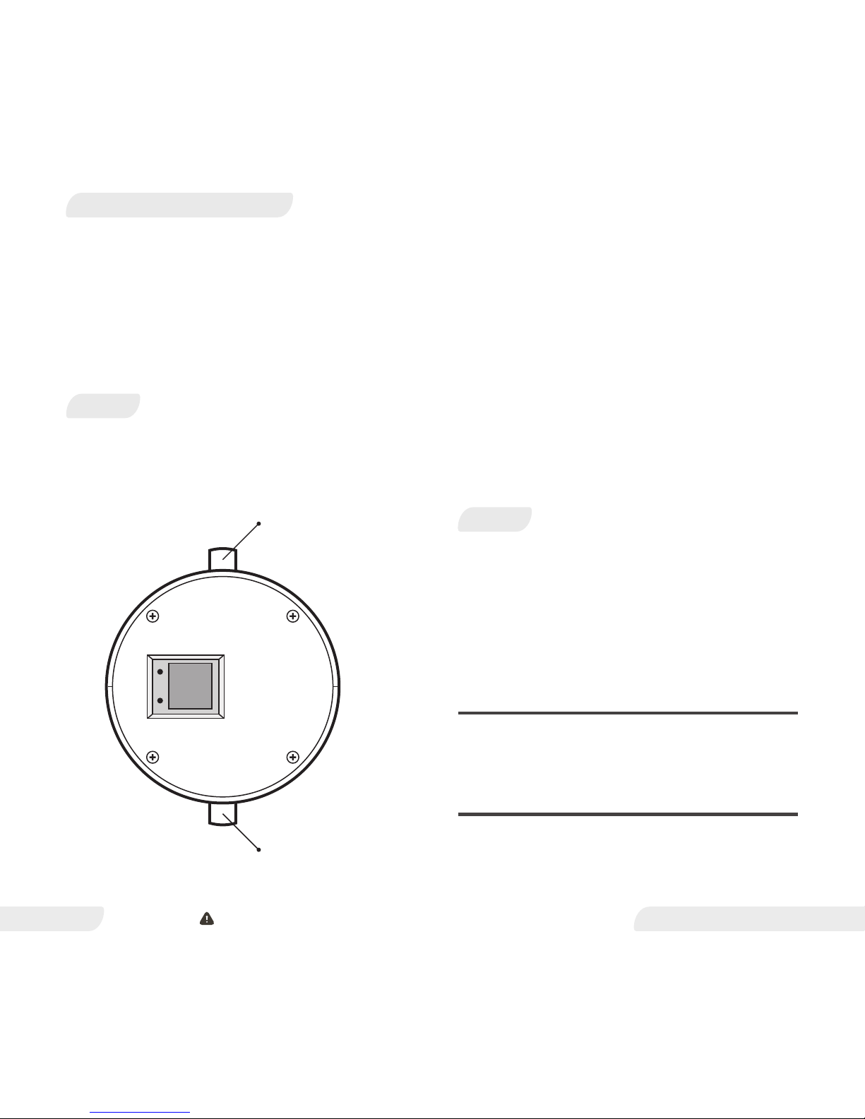
CONTROL END
Control Buttons
Inlet / Bottom
Top / Outlet
CAUTION: Breaker must remain off until installation is complete.

8) The display will now read “15” amps.
9) Press the up and down buttons to select your desired
maximum amperage. Amperage can be selected in 5 amp
increments from 15-48 amps.
10) Press and release both buttons simultaneously to
save the new setting.
11) Digital display will now read the default temperature
setting of “115” °F.
www.myheatworks.com
9
YOU ARE NOW READY TO ADJUST THE TEMPERATURE
Please continue to page 10
CAUTION: Breaker must remain off until installation is complete.
After the MODEL 1 has been properly installed and is
receiving power, the digital display will show the current
water temperature setting. The average shower
temperature is between 104 ° and 110 ° F (40 ° and 43 ° C).
SWITCHING BETWEEN FAHRENHEIT AND CELSIUS
www.myheatworks.com
10
2) Select temperature between 50 °F (4 °C) and 120 °F
(49 °C).
3) Verify your desired temperature appears on the digital
display.
HEATWORKS RECOMMENDS: Because newer model
dish washers are typically equipped with an internal
heating element, and most laundry detergents are
intended for use in cold or warm water, there is no
longer a need to set your water heater to a temperature
above 120 °F.
STEPS
1) Press both buttons at the same time and release the
bottom button for °C.
2) Press both buttons at the same time and release the
top button for °F.
STEPS
1) Press the top button to increase the temperature
setting. Press the bottom button to decrease the
temperature setting.
CONGRATULATIONS!
YOU HAVE COMPLETED THE INSTALLATION OF THE
HEATWORKS MODEL 1.
Outlet / Top
Inlet / Bottom
ADJUSTING THE TEMPERATURE
CAUTION: Breaker must remain off until installation is complete.
 Loading...