

Heat Wagon VG1000 User Manual
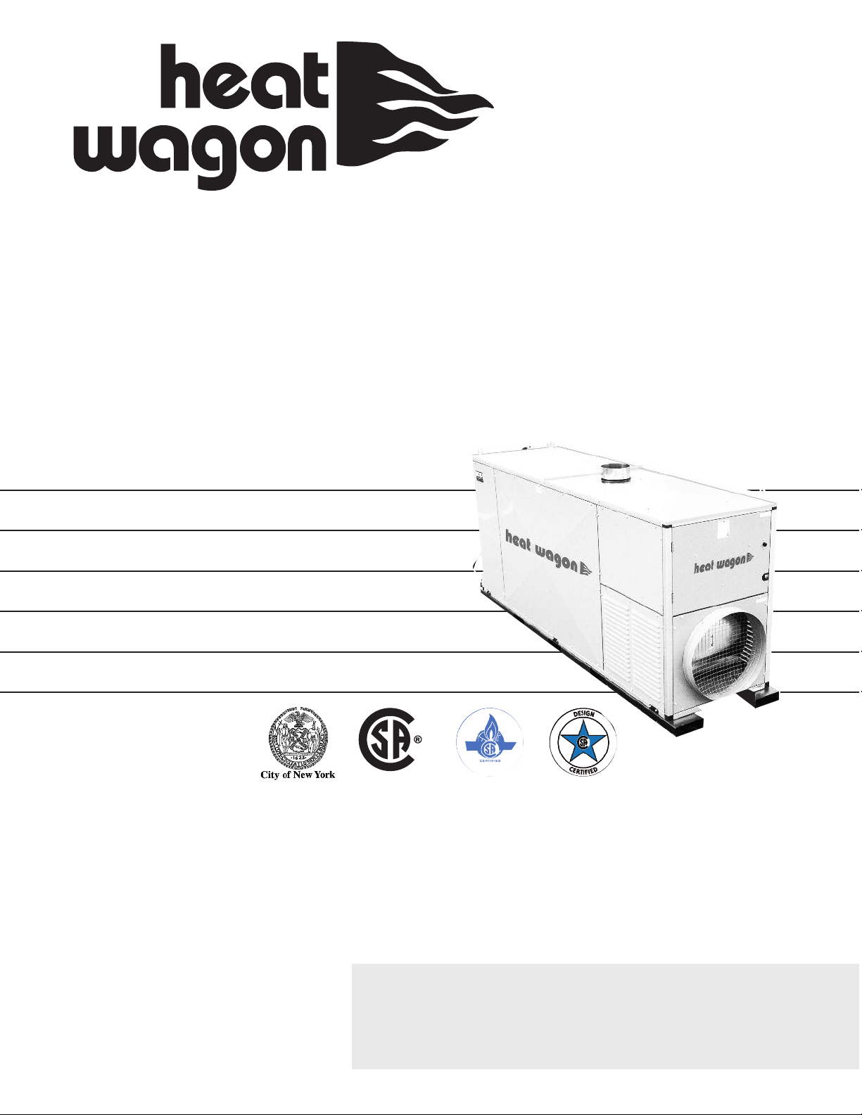
VG1000
C US
342 N. Co. Rd. 400 East
Valparaiso, IN 46383
219-464-8818 • Fax 219-462-7985
www.heatwagon.com
Installation and Maintenance Manual
Please retain this manual for future reference.
Construction
Heater
Dept. of Buildings
29-05-E
For your safety: Do not use this heater in
a space where gasoline or other liquids
having flammable vapors are stored.
Revision 1-16

IMPORTANT INFORMATION! READ FIRST
The heater is designed for use as a construction heater under ANSI Z83.7a-2000. Heater is not intended for use in pest remediation. The primary purpose of construction heaters is to provide
temporary heating of buildings under construction, alteration, or repair and to provide emergency
heat. Properly used, the heater provides safe, economical heating. Products of combustion are
vented outside the area being heated.
The heater IS NOT designed as an Unvented Gas Fired Room Heater under ANSI-Z21.11.2 and
SHOULD NOT be used in the home.
ANSI A119.2(NFPA 501C)-1987 Recreational Vehicle Standard prohibits the installation or storage
of LP-gas containers even temporarily inside any recreational vehicle. The standard also prohibits
the use of Unvented Heaters in such vehicles.
NFPA-58 1989 STANDARD FOR THE STORAGE AND
HANDLING OF LIQUEFIED PETROLEUM GASES
Use of the heater must be in accordance with this Standard and in compliance with all governing
state and local codes. Storage and handling of propane gas and propane cylinders must be in accordance with NFPA 58 and all local governing codes.
We cannot anticipate every use which may be made for our heaters. CHECK WITH YOUR LOCAL
FIRE SAFETY AUTHORITY IF YOU HAVE QUESTIONS ABOUT LOCAL REGULATIONS.
Other standards govern the use of fuel gases and heat producing products in specific applications.
Your local authority can advise you about these.
FOR YOUR SAFETY
DO NOT USE THIS HEATER IN A SPACE WHERE GASOLINE OR OTHER LIQUIDS HAVING FLAMMABLE VAPORS ARE STORED OR USED.
CONSTRUCTION HEATER GENERAL HAZARD WARNING:
Failure to comply with the precautions and instructions provided with this heater, can
result in death, serious bodily injury and property loss or damage from hazards of fire,
explosion, burn, asphyxiation, carbon monoxide poisoning, and/or electrical shock.
Only persons who can understand and follow the instructions should use or service
this heater.
If you need assistance or heater information such as an instruction manual, labels,
etc., contact your local Heat Wagon dealer or the manufacturer.
W A R N I N G
Fire, burn, inhalation, and explosion hazard. Keep solid combustibles, such as building materials, paper or cardboard, a safe distance away from the heater as recommended by the instructions. Never use the heater in spaces which do or may contain
volatile or airborne combustibles, or products such as gasoline, solvents, paint thinner, dust particles or unknown chemicals.
Not for home or recreational vehicle use!
If you have read this entire manual and you still have ques-
tions, please call us at 219-464-8818

Installation and Maintenance Manual
Model VG1000
Construction Heater
Table of Contents:
Page
Safety & Caution . . . . . . . . . . . . . . . . . . . . . . . . . . . . . . . . . . . . . . . . . . . .4
Specifications . . . . . . . . . . . . . . . . . . . . . . . . . . . . . . . . . . . . . . . . . . . . . . .4
Operating Instructions . . . . . . . . . . . . . . . . . . . . . . . . . . . . . . . . . . . . . . . .5
Troubleshooting . . . . . . . . . . . . . . . . . . . . . . . . . . . . . . . . . . . . . . . . . . . . .8
Maintenance . . . . . . . . . . . . . . . . . . . . . . . . . . . . . . . . . . . . . . . . . . . . . . .13
Illustrated Parts Breakdown . . . . . . . . . . . . . . . . . . . . . . . . . . . . . . . . . . .16
Wiring Diagrams . . . . . . . . . . . . . . . . . . . . . . . . . . . . . . . . . . . . . . . . . . .23
Exhaust Flue Pipe Guidelines . . . . . . . . . . . . . . . . . . . . . . . . . . . . . . . . .30
Setting the Pilot . . . . . . . . . . . . . . . . . . . . . . . . . . . . . . . . . . . . . . . . . . . .31
WARRANTY
This heater is guaranteed against defective materials and workmanship for one (1) year from Heat Wagon invoice
date.
Warranty repairs may be made only by an authorized, trained and certified Heat Wagon dealer. Warranty repairs by
other entities will not be considered. Warranty claims must include model number and serial number. Components
are guaranteed to the extent of the component manufacturer’s warranty.
LIMITATIONS
Warranty claims for service parts (wear parts) such as spark plugs, igniters, and flame rods will not be allowed. Diagnostic parts such as voltage meters and pressure gauges are not warrantable. Evidence of improper fuel usage,
fuel pressures outside of manufacturer’s specification, poor fuel quality, improper electric power, misapplication
and/or evidence of abuse may be cause for rejection of warranty claims.
Labor, travel time, mileage and shipping charges will not be allowed. Minor adjustments to heaters are the responsibility of the dealer. Defective parts must be tagged and held for possible return to the factory for 60 days from
date of repair. The factory will provide a return goods authorization, (RGA) for defective parts to be returned. No
warranty will be allowed for parts not purchased from Heat Wagon.
342 N. Co. Rd. 400 East • Valparaiso, IN 46383
219-464-8818 • 888-432-8924 • Fax 800-255-7985
www.heatwagon.com

SAFETY & CAUTION
• Instructions given in this manual and the applicable regulation of the local authorities
must be followed.
• The unit may be operated only by those persons who have been instructed in its proper use.
• The unit is to be installed and operated in such a way as to ensure the safety of employees and
surroundings.
• Never cover the unit’s air openings.
• Always ensure adequate fresh air supply to the unit.
• Never stand in front of the discharge end of the heater.
• Keep a minimum clearance of 10 feet from the fuel source. Storing and use of liquid fuel must
comply with the regulation and instructions given by the local authorities.
• Unit’s emitted noise level at the range of 3 feet: 74 dBA.
• Do not introduce foreign objects into the unit.
• Do not expose the unit to direct water jets.
• All electric cables outside the unit are to be protected against damage.
• Always disconnect the unit from power supply and turn off the gas supply when maintenance
or service is being performed.
• IF NOT OPERATED WITHIN GUIDELINES OF THESE OPERATING INSTRUCTIONS,
MANUFACTURER WILL NOT BE HELD RESPONSIBLE AND WARRANTY
WILL BECOME VOID.
SPECIFICATIONS
Model No. VG1000
Fuels: Vapor Propane or Natural Gas
Gas Inlet 1-1/4” FNPT (Both Wayne & Midco Burner)
Capacity: 1,000,000 BTU/HR
Blower: 4,075 CFM 5.0HP 2.0”SP
Electrical Rating: 240 Volts, 1
Fuel Consumption: NG-1000 CFH / Propane-11 GPH
Remote Thermostat: On/Off
Max. Discharge Temp.: 200ºF @ 0ºF Ambient
Duct Size: 20” Dia., 200 ft. max (straight)
Shp. Dimensions: 120”L x 31.5”W x 54”H
Weight (approximate): 1,300 lbs.
Gas Supply: Inlet Pressure Manifold Pressure Pilot Orifice
Midco Burner Max W.C. Min W.C. W.C.
Vapor Propane 14” W.C. 9” W.C. 2.6” .046
Natural Gas 14” W.C. 9” W.C. 4.1” .052
Ø 30 Amps
Wayne Burner Max W.C. Min W.C. W.C.
Vapor Propane 14” W.C. 9” W.C. 3.0” N/A
Natural Gas 14” W.C. 9” W.C. 4.6” N/A
4

OPERATING INSTRUCTIONS
INSTALLATION
• When transporting, use all four lifting eyes in upper corners or forklift openings in the base of
the units.
• Place the unit on a level and non-combustible surface.
• Minimum clearances from combustibles:
- outlet, minimum 10 feet
- sides, minimum 3 feet
- top, minimum 3 feet
- flue pipe exhaust, gas discharge minimum 2 feet
• Manufacturer recommends a free zone of 5 feet around the unit and a minimum distance of 10
feet at the unit’s flue gas openings are to be maintained.
• If the unit is placed indoors, secure an adequate fresh air opening for the burner combustion air.
• The unit may not be installed and operated in premises where explosive or combustible fumes
or dust are present. Always check the regulation of local authorities.
• Be certain that neither the air inlet nor the air outlet is obstructed.
FUEL SUPPLY
• This heater is shipped as either natural gas or vapor propane. Check for proper pilot orifice in
burner (Midco burner only).
Natural Gas .052
Vapor Propane .046
• Be certain to use adequate hose or pipe size to ensure proper volume and pressure.
See Chart Below.
Hose BTU
Length 1 Million
in Feet <1PSI 1PSI 2PSI 5PSI
10 1-1/2 1-1/4 3/4 3/4
25 2 1-1/4 3/4 3/4
35 2 1-1/4 3/4 3/4
50 2 1-1/4 1 3/4
75 2 1-1/4 1-1/4 3/4
100 2 1-1/4 1-1/4 3/4
125 2-1/2 1-1/2 1-1/4 1
150 2-1/2 1-1/2 1-1/4 1
175 2-1/2 1-1/2 1-1/4 1
200 2-1/2 1-1/2 1-1/4 1-1/4
225 2-1/2 1-1/2 1-1/4 1-1/4
VAPOR PROPANE QUICK
REFERENCE HOSE
Hose BTU
Length 1 Million
in Feet 1/2PSI 10PSI
10 1-1/4 3/4
25 1-1/4 3/4
35 1-1/2 3/4
50 1-1/2 3/4
75 2 3/4
100 2 3/4
125 2 3/4
150 2 3/4
175 2 3/4
200 2 3/4
225 2 3/4
NATURAL GAS QUICK
REFERENCE HOSE
For supply pressures greater than 1/2psi
• A regulator must be installed on the heater to ensure that the pressure to the heater does not
exceed 1/2 psi inlet pressure. Excessive pressures over 1/2 psi (14” W.C.) will damage controls
and void warranty.
5

FUEL SUPPLY (CONTINUED)
• Ensure that for the surrounding temperature, size and capacity of the propane supply cylinder
is adequate to provide the rated Btu/hr input to the heater.
• Visually inspect the hose assembly and ensure that it is protected from traffic, building
materials, and contact with hot surfaces. If it is evident that there is excessive abrasion or wear,
or the hose is cut, replace it immediately.
• Purge air from line and wait 10 minutes for gas to dissipate.
• After installation, check the hose assembly for gas leaks by applying a water and soap solution
to each connection.
• Fuel hose must be UL approved.
• The installation of this heater to a natural gas supply must confirm with all applicable local
codes or, in the absence of local codes, with the National Fuel Gas Code ANSI Z223.1/NFPA 54.
For vapor propane, refer to standard for Storage and Handling of Liquified Petroleum Gases
ANSI/NFPA 58.
ELECTRICAL
• Electric cable extensions must be connected by qualified authorized electricians based on the
unit capacity and cable length.
• Connect unit to a power supply with a suitable appliance receptacle (30 Amp). Green
indicator lamp will light up.
• Confirm voltage at heater connection (208V min.) to ensure proper operation.
EXHAUST FLUE PIPE
• The unit is to be connected to a flue pipe with adequate draft, to ensure the proper start and
operation of the unit. Refer to page 27.
• The flue pipe is to be made of non-combustible material and clearances from combustible
materials must be a minimum 8 inches (temperature of flue gases is approximately 410º F).
• The flue pipe and its installation must comply with the regulations and instructions given by
the local authorities.
START UP
• Only people trained in the operation and supervision of this heater should operate
and maintain the unit.
• Check the unit to make certain that there are no visible defects on the control and safety
devices and that the unit has been installed correctly.
1. Open door at back of unit (control box compartment).
2. Check that the control switch in the control box is in position “0” (STOP).
3. Pre-select desired room temperature on the room thermostat. The temperature must be set
higher than the ambient temperature.
4. Open all possible shut-off devices of the fuel supply lines and push the reset on the low
pressure gas switch (Wayne Burner Only).
6
START UP (CONTINUED)
5. Turn the control switch in control box to position “1” (HEATING).
6. When the ambient temperature level is lower than thermostat setting, the burner switches
on automatically. The fan does not switch on until the set temperature (104ºF) of the heat exchanger has been reached (will take approximately 1-5 minutes).
7. The green indicator lamps for “heating on” and “fan on” will light up now.
8. Close the door in order to protect the unit against unauthorized adjustments.
• After startup, the heater is operated automatically by the room thermostat and governed by all
control devices, including the safety limit controls.
• The room thermostat (TSTAT) and burner sensor control the running sequences of the
burner and the fan sensor controls the fan function.
• Overheat limit reset (STB) controls and shuts off the heater (burner) in the case of overheating.
• The unit can also be used for ventilation purposes only, if needed.
1. Turn the control switch in control box to position “2” (VENTILATION).
2. The unit is now in the continuous ventilating mode.
3. Heating is not possible in this mode.
DUCTING (Warm Air)
• Minimum clearance from combustible materials is 4 inches.
• Use steel ducting or fabric ducting capable of withstanding maximum temperature of 300ºF.
• Maximum length of duct: 200’ (straight).
• Duct diameter: 20”.
• Make certain that the duct is safely and properly fastened to the warm air outlet.
• Avoid sharp bends and corners to ensure maximum air flow and avoid back pressure that can
cause heat accumulation in heater.
• FAILURE TO COMPLY WITH THESE RECOMMENDATIONS COULD RESULT IN SHUTDOWN
OF THE HEATER.
SHUT DOWN
• Turn control switch to position “0” (STOP).
• Close fuel supply.
Important!
The air supply fan continues running for several minutes to cool down the combustion
chamber/heat exchanger. The fan can restart several times before finally switching off!
WARNING!
ELECTRICAL POWER TO THE UNIT MAY BE DISCONNECTED IN EMERGENCY SITUATIONS
ONLY. OTHERWISE, DO NOT STOP THE UNIT BY DISCONNECTING POWER. UNIT NEEDS
TO COOL DOWN USING ITS OWN FAN. FAILURE TO COMPLY WITH PROPER SHUT-DOWN
PROCEDURES CAN CAUSE DAMAGE TO THE COMBUSTION CHAMBER, HEAT
EXCHANGER, SAFETY FEATURES AND VOID WARRANTY.
7

on the left hand side of the burner.
• Burner motor relay is located in the main control box (K2). Check between
• Reset the switch, which is located in the burner compartment on the gray box
• Reset the blue button on the flame safeguard control.
• Test for 240 volts (min 208) between L1 and L2 on the main terminal block.
• On the heater control unit (HCU) disconnect the wires from terminals X10 and
• On the main terminal block, check for 120 volts between terminals 8 and N
replace HCU.
when the 3-position switch is in the HEAT position. If less than 105 volts,
Replace sensor if reading is out of range.
reading. Compare to Sensor Resistance Chart page 25.
X11. Using an ohm meter, check the resistance between the two wires for a
relay.
ground and L1, then ground and T1 for 120 volts. If less than 105 volts replace
1/4” NPT inlet. Install gauge in the pressure tap port located on the output side
• (Midco Burner) Use a low pressure gauge (0-15 inches of water column) with a
• Check for dirt or ice buildup on the air inlet or blower wheel. If using duct on
• Adhere to the proper shut down procedures.
fails test. The limit switch is located in the upper left hand corner of burner
compartment.
the two male terminals at room temperature. Replace if overheat limit switch
its own when cool. Test overheat limit switch for continuity between
Power must remain at the unit until it cools down fully. Blower will shut down on
.2” W.C. Check with magnehelic gauge if necessary.
the air outlet, ensure the back pressure does not exceed a static pressure of
for propane or 3.5 inches of W.C. for natural gas.
propane or 4.1 inches of W.C. for natural gas. (Wayne Burner) 3 inches of W.C.
Maxitrol RV81 regulator) in or out until the gauge reads 2.6 inches of W.C. for
pressure by turning the pressure adjusting screw (located in the center of the
of the last gas solenoid valve in line. Run unit and adjust the manifold
VG1000 TROUBLESHOOTING
8
safeguard control box is engaged
• Burner reset button on the burner flame
• Power supply cord
position #1
heater to
1. Turn the
Symptom Possible Causes Possible Solutions
• Burner motor relay
• Overheat limit switch is tripped
happens.
and nothing
• Burner sensor
• Heater control unit (HCU)
• Incorrect burner manifold pressure
runs for a little
while, but
2. The heater
shuts down. It
• Restricted airflow
limit switch is
won’t come on
again until the
• Overheat limit switch
reset.

Install gauge in the pressure tap port located on the output side of the gas
• See instructions on page 31
• Use a low pressure gauge (0-15 inches of water column) with 1/8” NPT inlet.
• Rough setting at 1/2 open. Minor adjustments from the rough settings can be
and 5 volts.
Adjust the air damper until the volt meter reads the highest voltage between 2
Flame Safeguard Control. Set the volt meter on DC volts and run the heater.
Insert volt meter probes into provided + and – terminals on the Honeywell
made to achieve a smooth sounding burner with no soot from the flue pipe.
Ensure proper purge procedure (see Fuel Supply Installation).
the Heat WagonEngineering Guide. Heater requires 9-14” W.C. inlet pressure.
the gauge reads the proper manifold pressure. Refer to pipe sizing charts in
screw (located on the input side top of the gas valve) counter clockwise until
valve. Run the heater. Adjust the pressure by turning the pressure adjusting
ignition wire and short it to ground. Pull the wire away from ground slowly. A
• Turn off the gas valve, turn on the burner. Use insulated pliers to hold the
• Clean with fine sandpaper. Make sure it is free from buildup or cracks.
• The burner airflow switch (located above blue Honeywell safeguard control) will
• If there is power at the flame safeguard control and no power out to the
• Make sure both reset buttons are depressed. (Items 14 and 15 on page 22)
valve.
between the terminals on the solenoid valve coil. If no continuity, replace gas
solenoid valves, replace the flame safeguard control. Check for continuity
switch (Midco Burner Only).
around the air switch. If this test solves the problem, adjust or replace the
tubes supplying air to the switch for any restrictions. ONLY AS A TEST, wire
not allow power to the flame safeguard control when it is open. Check the
distance of 3/8 of an inch for a duration of 4-5 seconds.
rainbow colored arc should travel between the wire and the ground at a
VG1000 TROUBLESHOOTING
• Electronic igniter
• Fuel pressure or volume
• Pilot (Midco Burner Only)
won’t ignite.
but the heater
comes on,
3. Burner motor
Symptom Possible Causes Possible Solutions
• Air inlet damper adjustment
• Ignition electrode
• Burner airflow switch
• Gas valve
(Wayne burner only)
• Pressure switches
9

made to achieve a smooth sounding burner with no soot from the flue pipe.
• Rough setting at 1/2 open. Minor adjustments from the rough settings can be
• Refer to the flue pipe chart in this manual. Check flue for restriction
• Clean the burner blower wheel with a small brush
and 5 volts.
Adjust the air damper until the volt meter reads the highest voltage between 2
Flame Safeguard Control. Set the volt meter on DC volts and run the heater.
Insert volt meter probes into provided + and – terminals on the Honeywell
Install gauge in the pressure tap port located on the output side of the gas
• Use a low pressure gauge (0-15 inches of water column) with 1/8” NPT inlet.
• Refer to the cleaning instructions in this manual.
the Heat Wagon Engineering Guide. Heater requires 9-14” W.C. inlet pressure.
the gauge reads the proper manifold pressure. Refer to pipe sizing charts in
screw (located on the input side top of the gas valve) counter clockwise until
valve. Run the heater. Adjust the pressure by turning the pressure adjusting
Insert volt meter probes into provided + and – terminals on the Honeywell
made to achieve a smooth sounding burner with no soot from the flue pipe.
• Rough setting at 1/2 open. Minor adjustments from the rough settings can be
and 5 volts.
Adjust the air damper until the volt meter reads the highest voltage between 2
Flame Safeguard Control. Set the volt meter on DC volts and run the heater.
• Refer to the flue pipe chart in this manual. Check flue for restriction
• Clean the burner blower wheel with a small brush
valve. Run the heater. Adjust the pressure by turning the pressure adjusting
Install gauge in the pressure tap port located on the output side of the gas
• Use a low pressure gauge (0-15 inches of water column) with 1/8” NPT inlet.
the Heat Wagon Engineering Guide. Heater requires 9-14” W.C. inlet pressure.
the gauge reads the proper manifold pressure. Refer to pipe sizing charts in
screw (located on the input side top of the gas valve) counter clockwise until
• Refer to the cleaning instructions in this manual.
VG1000 TROUBLESHOOTING
10
restrictions
• Gas manifold pressure
• Flue pipe setup or flue pipe
• Air damper setting
rumbling
sound.
has a loud
4. The heater
Symptom Possible Causes Possible Solutions
• Dirt on burner blower wheel
• Heat exchanger
• Air damper setting
smoke out of
the vent stack.
blows black
5. The heater
restrictions
• Dirt on burner blower wheel
• Gas manifold pressure
• Flue pipe setup or flue pipe
• Heat exchanger
 Loading...