

Page 1
C US
342 N. Co. Rd. 400 East
Valparaiso, IN 46383
219-464-8818 • Fax 219-462-7985
www.heatwagon.com
Installation and Maintenance Manual
Please retain this manual for future reference.
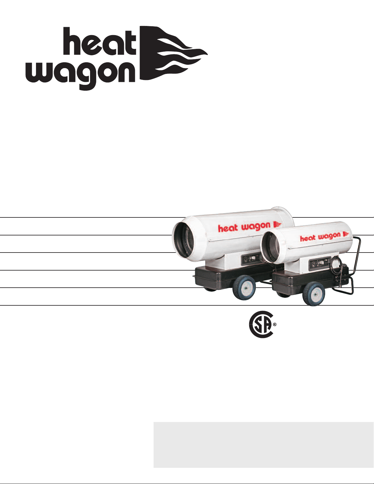
DF400/DF600
Construction
Heaters
For DF400 Models
SN 27601001 and beyond
For DF600 Models
SN 27701501 and beyond
For your safety: Do not use this heater in
a space where gasoline or other liquids
having flammable vapors are stored.
Revision 5-16
Page 2

CONSTRUCTION HEATER GENERAL HAZARD WARNING:
F
ailure to comply with the precautions and instructions provided with this heater,
can result in death, serious bodily injury and property loss or damage from hazards
of fire, explosion, burn, asphyxiation, carbon monoxide poisoning, and/or electrical
shock.
Only persons who can understand and follow the instructions should use or service
this heater.
If you need assistance or heater information such as an instruction manual, labels,
etc., contact your local Heat Wagon dealer or the manufacturer.
Heater is not intended for use in pest remediation.
W A R N I N G
Fire, burn, inhalation, and explosion hazard. Keep solid combustibles, such as building materials, paper or cardboard, a safe distance away from the heater as recommended by the instructions. Never use the heater in spaces which do or may contain
volatile or airborne combustibles, or products such as gasoline, solvents, paint thinner, dust particles or unknown chemicals.
Not for home or recreational vehicle use!
Page 3

Installation and Maintenance Manual
Model DF400 - DF600
Construction Heater
Table of Contents:
Page
Control Board . . . . . . . . . . . . . . . . . . . . . . . . . . . . . . . . . . . . . . . . . . . . . . .4
Recommendations . . . . . . . . . . . . . . . . . . . . . . . . . . . . . . . . . . . . . . . . . . .5
Operation . . . . . . . . . . . . . . . . . . . . . . . . . . . . . . . . . . . . . . . . . . . . . . . . . .5
Safety . . . . . . . . . . . . . . . . . . . . . . . . . . . . . . . . . . . . . . . . . . . . . . . . . . . . . .5
Maintenance . . . . . . . . . . . . . . . . . . . . . . . . . . . . . . . . . . . . . . . . . . . . . . . .5
Troubleshooting . . . . . . . . . . . . . . . . . . . . . . . . . . . . . . . . . . . . . . . . . .6-11
Sequence of Operation . . . . . . . . . . . . . . . . . . . . . . . . . . . . . . . . . . . . . .10
Specifications . . . . . . . . . . . . . . . . . . . . . . . . . . . . . . . . . . . . . . . . . . . . . .12
Wiring Diagrams . . . . . . . . . . . . . . . . . . . . . . . . . . . . . . . . . . . . . . . . .14-15
Parts Breakdown . . . . . . . . . . . . . . . . . . . . . . . . . . . . . . . . . . . . . . . . .16-19
WARRANTY
All new Heat Wagon and Sure Flame heaters and fans are guaranteed against defective materials and workmanship for one (1) year from invoice date.
Warranty repairs may be made only by an authorized, trained and certified Heat Wagon dealer. Warranty
repairs by other entities will not be considered. Warranty claims must include model number and serial
number.
LIMITATIONS
Warrant claims for service parts (wear parts) such as spark plugs, igniters, flame rods will not be allowed.
Diagnostic parts such as voltage meters and pressure gauges are not warrantable.
Evidence of improper fuel usage, fuel pressures outside of manufacturer’s specification, poor fuel quality,
and improper electric power, misapplication or evidence of abuse may be cause for rejection of warranty
claims.
Travel time, mileage and shipping charges will not be allowed. Minor adjustments of heaters are dealers’
responsibility. Defective parts must be tagged and held for possible return to the factory for 60 days from
date of repair. The factory will provide a return goods authorization, (RGA) for defective parts to be
returned.
No warranty will be allowed for parts not purchased from Heat Wagon.
342 N. Co. Rd. 400 East • Valparaiso, IN 46383
219-464-8818 • 888-432-8924 • Fax 800-255-7985
www.heatwagon.com
Page 4
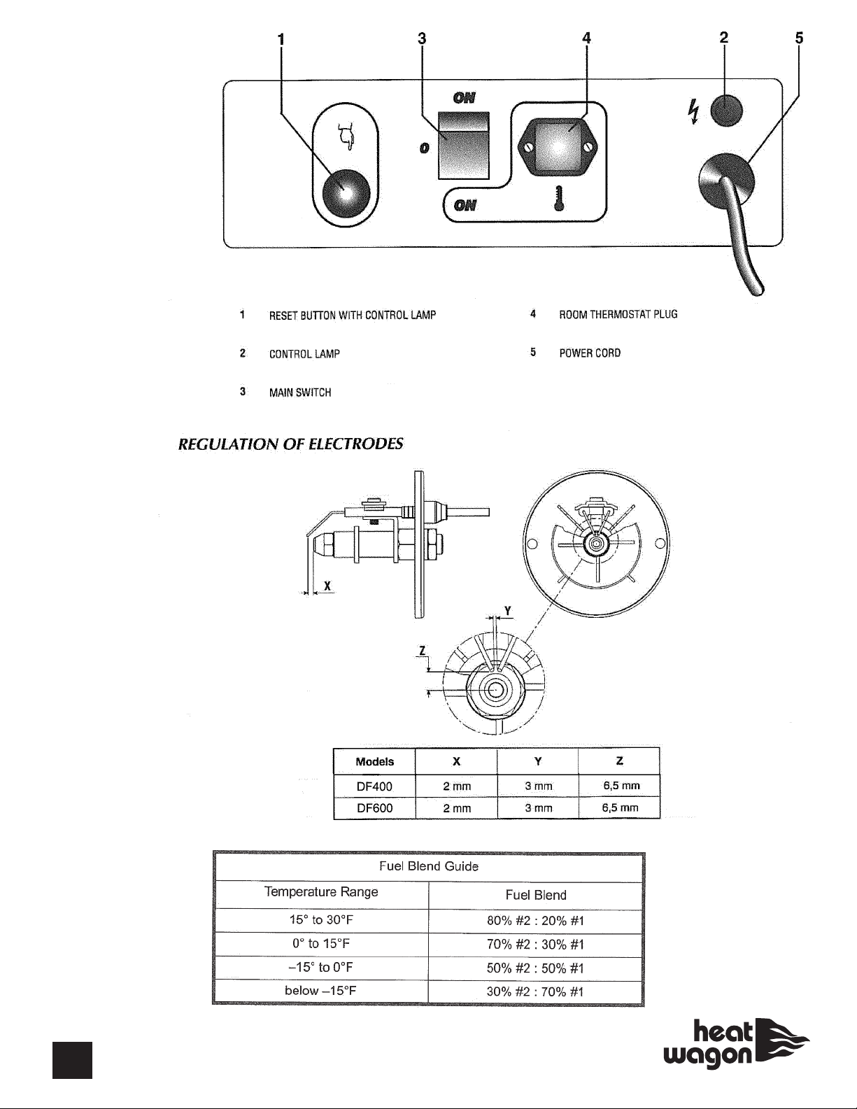
Control Board
A
B
A-No Thermostat
B-With Thermostat
4
Note: 1mm = 0.039 inch
#1 Kerosene
#2 Diesel Fuel (Winter Blend)
Page 5
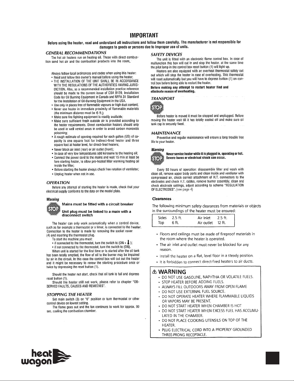
5
Page 6
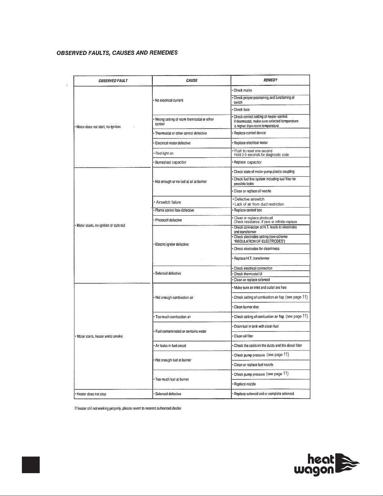
See page 11.
6
Page 7

ADVANCED TROUBLESHOOTING
otor runs, no visible ignition and heater reset (red light) comes on
M
Causes:
1. Fuel filter is dirty.
2. Spray nozzle clogged.
. Air proving switch defective.
3
4. Air entering the fuel pump thru the inlet line.
5. Safety thermostat defective or tripped.
6. Fuel pump is defective/or broken pump coupling.
7. Solenoid valve is defective.
8. Control board is defective.
9. Defective transformer.
Solutions:
1. Fuel filter dirty. Check the external and internal fuel filters and clean or replace as necessary. Most fuel pumps contain an internal fuel filter
located where the inlet line enters the fuel pump.
2. Spray nozzle clogged. Remove and inspect the spray nozzle. Clean or replace as needed. Do not clean the nozzle orifice with anything
metal as this may enlarge the orifice.
3. Air proving switch is defective. Try to start the heater without ducting. Oil heaters have an air proving switch wired between the control
board and the solenoid valve. (Review Sequence of Operation, page 10). The air proving switch is normally open and requires air from the
turning fan blade to close the switch and send power to the solenoid valve. Set a multi-meter to measure voltage. With the fan blade turning,
check for voltage coming out of the air proving switch to the solenoid valve. If no voltage is read, next check for voltage at the control board
terminals out to the air proving switch. If voltage at the control board is read, the air proving switch is defective. If no voltage is read at the
board, the control board is defective.
*NOTE: Top cover shell of heater needs to be
attached during troubleshooting (will affect
operation of airswitch and photocell).
4. Air entering the fuel pump thru the fuel inlet line. If air enters the pump it will lose its prime and will not maintain adequate pump pressure.
First make sure all fittings, including the fuel filter on the inlet line are tight. If you still suspect air is entering the pump, start eliminating portions of the inlet line until the air leak is found. Start this process at the fuel tank end of the inlet line. It may be necessary to draw fuel from a
small container rather than the fuel tank.
5. Safety thermostat defective or tripped. Also called overheat switch. Some oil heaters have a safety thermostat wired between the control
board and the solenoid valve. If the heater becomes too hot this normally closed switch will open and interrupt power to the solenoid valve.
Use a multi-meter set to measure ohms. Place the multi-meter probes on the two male terminals of the safety thermostat. If the multi-meter
shows infinity (no continuity) the safety thermostat is defective. If the switch opens up before the heater becomes hot, the safety thermostat is
defective.
6. Fuel pump is defective. The output pressure of the fuel pump can be checked by placing a high pressure fuel gauge into the gauge port of
the fuel pump. Use a gauge with enough capacity to measure the high pressure your particular heater can produce. Use the adjustment on the
pump to set the pump pressure to the manufacturer’s specification. If you do not have a fuel gauge, you may slightly loosen the pump’s output
line connection and place a rag there. Run the heater briefly and see if fuel reaches the rag. If no fuel is pumped, check the connection
between the motor and the fuel pump to make sure the motor can turn the pump. Also check the external and internal fuel filters for blockage,
and clean or replace if necessary. The fuel pumps internal filter is usually located where the fuel inlet line enters the pump. Check to make
sure motor is rotating pump. (BIE 99AM003 Gauge Kit, optional accessory)
7. Solenoid valve is defective. Call tech service for assistance.
8. Control board defective. Use a multi-meter set to measure voltage. Take a voltage reading on the control board terminals that send input
power to the transformer. If proper voltage is not present, the control board is defective. Check fuse on control board.
7
Page 8

ADVANCED TROUBLESHOOTING CONTINUED
9. Defective transformer.
Call Tech Service.
Heater ignites, runs less than one minute and the flame/safety control trips.
Causes:
1. Photocell dirty or defective.
2. Flame/safety control defective.
Solutions:
1. Photocell dirty or defective.
If the photocell “eye” is dirty, it may be cleaned with a soft dry cloth. Should a cleaner be necessary, use an alcohol based cleaner that will dry
completely without leaving an oil residue. If the photocell is clean and this symptom continues, remove the photocell for testing. Measure resistance, if zero or infinite-replace photocell.
2. Flame/safety control defective.
The easiest way to test the flame/safety control is to prove the photocell is good or bad using one of the two preceding tests under “1.
Photocell dirty or defective”. If the jumper test will not run the heater or the photocell passes the ohm test, the flame/safety control is defective.
Heater ignites, runs several minutes and shuts down.
Causes:
1. Photocell dirty or defective.
2. Fuel filter dirty.
3. Fuel pump is defective.
Solutions:
1. Photocell dirty or defective.
See “1. Photocell dirty or defective” for instructions on cleaning and testing the photocell.
2. Fuel filter dirty.
See “1. Fuel filter dirty”
3. Fuel pump is defective.
See “6. Fuel pump is defective”
8
Page 9

ADVANCED TROUBLESHOOTING CONTINUED
Heater ignites, but combustion is poor or uneven.
Causes:
. Fuel pump is defective.
1
2. Spray nozzle clogged.
3. Fuel filter dirty.
4. Spark plug or electrode(s) not gapped or positioned properly.
5. Weak spark output from transformer.
6. Fuel contaminated by water or impurities.
Solutions:
1. Fuel pump is defective.
See “6. Fuel pump is defective”
2. Spray nozzle clogged.
See “2. Spray nozzle clogged”
3. Fuel filter dirty.
See “1. Fuel filter dirty”
4. Spark plug or electrode(s) not gapped or positioned properly.
See page 4.
5. Weak spark from transformer.
See “9. Defective transformer”
6. Fuel contaminated by water or impurities.
Using a flashlight, inspect the fuel in the tank for water or impurities. Bubbles on the bottom of the tank indicate water in the fuel tank. Water
can be removed from the tank by adding an additive to the tank that is designed to dry up moisture in fuel tanks. This type of additive can be
purchased at most automotive supply stores. This is also advisable if the fuel filter contains water or impurities.
Motor and transformer do not operate.
Causes:
1. Incorrect or low voltage supplied to the heater.
2. Fuse in heater is blown. (no green light)
3. Thermostat defective, or not turned up to call for heat.
4. Control board is defective.
5. Reset button has not been reset. (red light on)
6. Wiring disconnected, loose or incorrect.
Solutions:
1. Incorrect or low voltage supplied to the heater. Most oil heaters require a minimum of 108 volts to operate properly. A multi-meter set to
measure volts can be used to check the amount of voltage at the end of the extension cord(s). If the measured voltage is too low, the length of
the extension cord (s) must be shortened or a thicker gauge extension cord must be used.
2. Fuse in heater is blown. Locate and remove the in-line fuse of the heater. Set a multi-meter to measure ohms of resistance. Place a multimeter probe on each end of the fuse. The multi-meter should read zero ohms (continuity) or the fuse is blown. If a new fuse blows immediately, check for possible causes. Check for incorrect voltage to the heater. Make sure the total amperage draw of all equipment running on the circuit is not too great. If the supplied voltage and total amperage draw are correct, check the wiring in the heater for correctness and possible
shorts.
9
Page 10

ADVANCED TROUBLESHOOTING CONTINUED
3. Thermostat is defective or not turned up to call for heat. Turn the thermostat up to the highest possible setting and try to start the heater.
Next set a multi-meter to measure voltage coming out of the thermostat. If approximately 120 volts is not measured, the thermostat is defec-
ive.
t
4. Control board is defective. Using a multi-meter set for volts, check the hot and neutral wires which bring voltage into the control board. If
proper voltage is reaching the board then the control board is defective.
5. Reset button has not been reset. Push the reset button and try to start the heater.
6. Wiring disconnected, loose or incorrect. With the heater unplugged, check the wiring from the cord to the terminal blocks, thermostat, and
flame/safety control. Consult the wiring diagram of your heater to make sure all these wires are connected properly.
Heater ignities, but flame is excessive.
Causes:
1. Pump pressure too high.
2. Incorrect fuel.
3. Worn nozzle.
.Solutions:
1. Pump pressure too high.
Use a high pressure fuel gauge attached to the pump’s gauge port to check the pump pressure. Use the pump’s pressure adjustment if the
pressure is higher than the manufacturer’s recommended setting.
2. Incorrect fuel.
Only use fuels recommended by the specific manufacturer of the heater. Never use gasoline, thinners, solvents, or any other flammable fluid. If
you suspect incorrect fuel, inspect carefully, then drain and replace if necessary.
3. Worn nozzle.
Over time, impurities in the fuel which are forced thru the nozzle under high pressure will enlarge the orifice and cause the heater to overfire or
run “rich”. Always check first for excessive pump pressure or incorrect fuel. If the pressure and fuel are both correct, a new nozzle is needed.
DF400/DF600 Sequence of Operation
Step 1 - Plug in power cord. Power flows thru the fuse to five places: the power indicator light, the fuel filter heating element,
the relay terminal #11, the electronic board and thru the control board to the three position on/off switch.
Step 2 - Turn switch to the On position. There are two choices for On with this switch. Selecting the upper On position allows
for continuous operation without attaching an external thermostat control. The upper On position will return power from the
On/Off switch to the control board. This will cause the control board to begin the ignition sequence. Choosing the lower On position will cycle the heater on and off with the attachment of an external thermostat control to the thermostat plug on the control
panel. When the external thermostat returns power to the control board the ignition sequence is initiated.
Step 3 - Control Board begins ignition sequence. First the board sends power to the relay terminal #A1. This joins relay contacts #11 and #14 sending power to the motor and transformer.
Step 4 - Control boards sends power to the solenoid valve. After the motor and transformer have received power for approximately 7 to 10 seconds the control board will send power to the solenoid valve. If the airswitch closes, the power to the solenoid
valve must travel thru an air pressure switch to reach the valve. Air switch is in series with solenoid valve.
Step 5 - Photocell must detect flame. After the control board sends power to the solenoid valve the photocell must detect the
presence of flame in about two seconds. If flame is not detected the reset light will come on and the control board will interrupt
power to the solenoid valve. The cool down phase will run as the control board will continue to power the relay and therefore the
motor for 90 seconds. When flame is detected by the photocell the control board will continue to power the solenoid valve, the
motor, and the transformer.
Step 6 - Turn Control Switch to Off position. The control board removes power to the solenoid valve and runs the motor for 90
seconds.
10
Page 11
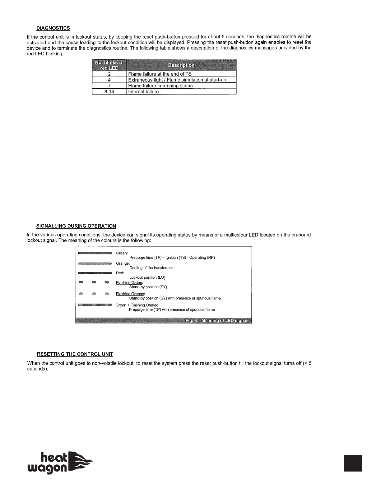
1.
FOR 2 RED BLINKS CAUSE MAY BE:
• No flame at 1st start up (review page 12 and 13)
• Other causes may be defective over heat limit switch (check for continuity)
FOR 4 RED BLINKS CAUSE MAY BE:
• Photocell senses light before start- up (make sure cover is on and photocell installed properly)
FOR 7 RED BLINKS CAUSE MAY BE:
• Out of fuel
• Filter or nozzle blocked
• Broken fuel line (intake sucking air)
• Bad photocell
• Overheat limit switch tripped
2.
3.
• Non-volatile lockout (manual reset), in order to reset the system, the reset button must be pressed (less than 5 seconds).
• Volatile lockout, hold reset button for a least one minute, red light should go out, let control board “reboot” for at least
another minute before attempting to start again.
11
Page 12
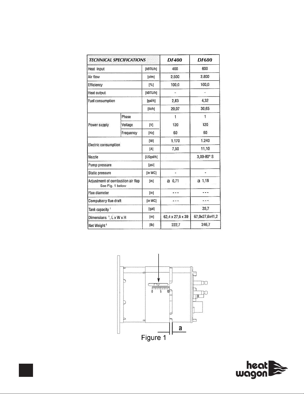
Technical Specifications
2,00-80ºS
165
190
N
N=7.5
28
12
Page 13
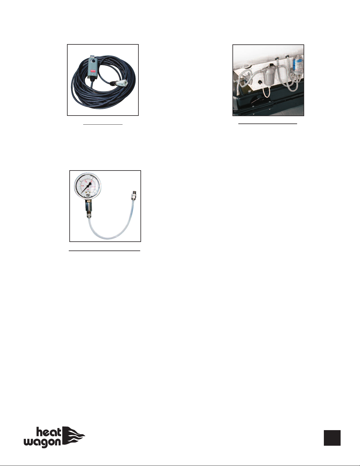
Accessories
THERMOSTAT
#THIDF
FUEL PRESSURE GAUGE
#BIE99AM003
EXTERNAL FUEL KIT
(allows access to
external fuel source)
#TK400
13
Page 14
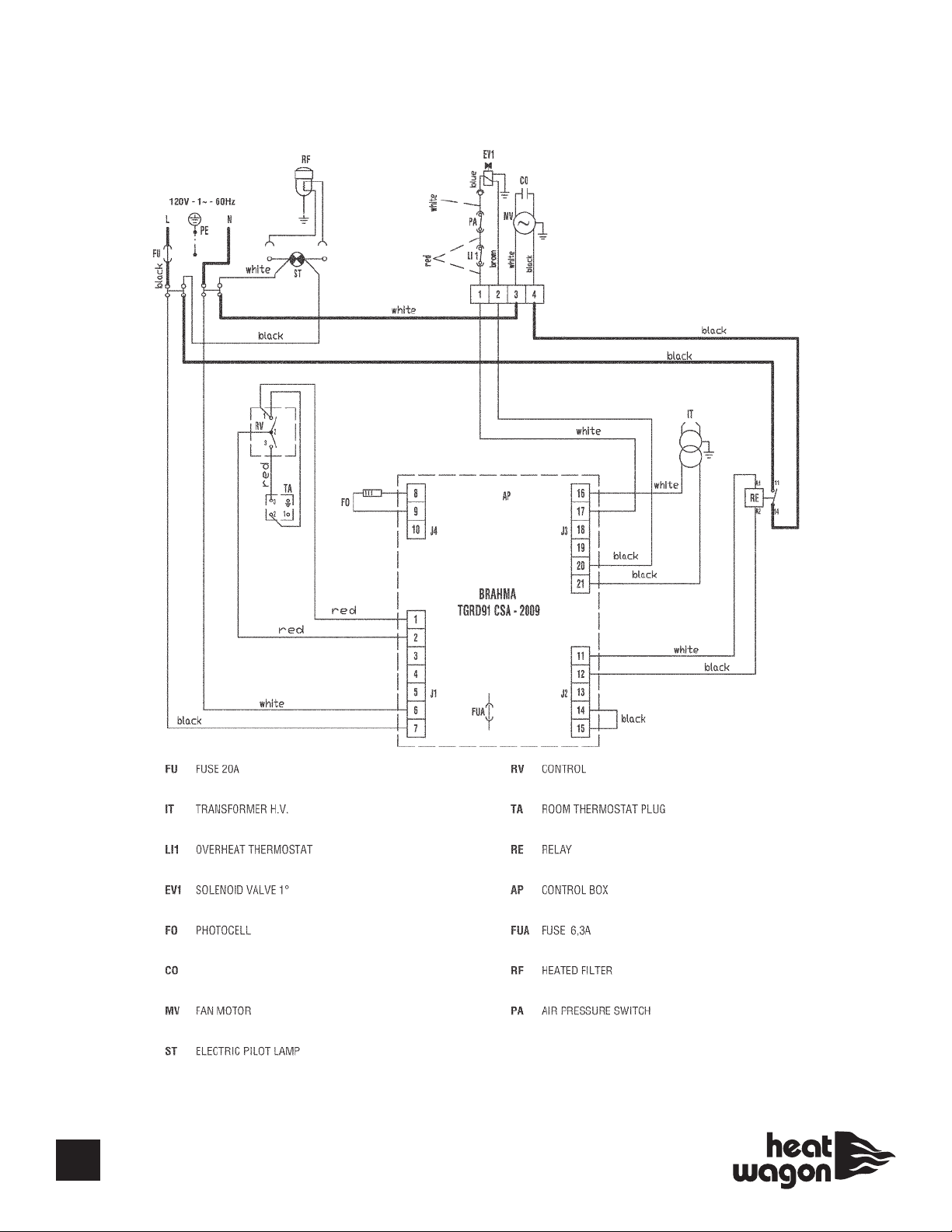
DF400 Wiring Diagram
SN 276000401 and Beyond
14
P/N - E10325
CAPACITOR
(100 MPa)
Page 15
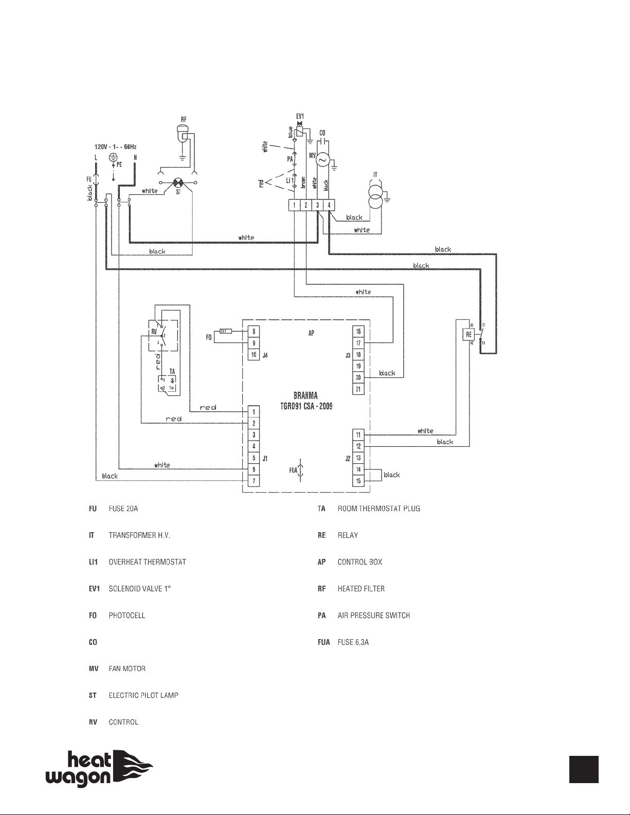
DF600 Wiring Diagram
SN 277000401 and Beyond
CAPACITOR
(200 MPa)
P/N - E10325
15
Page 16
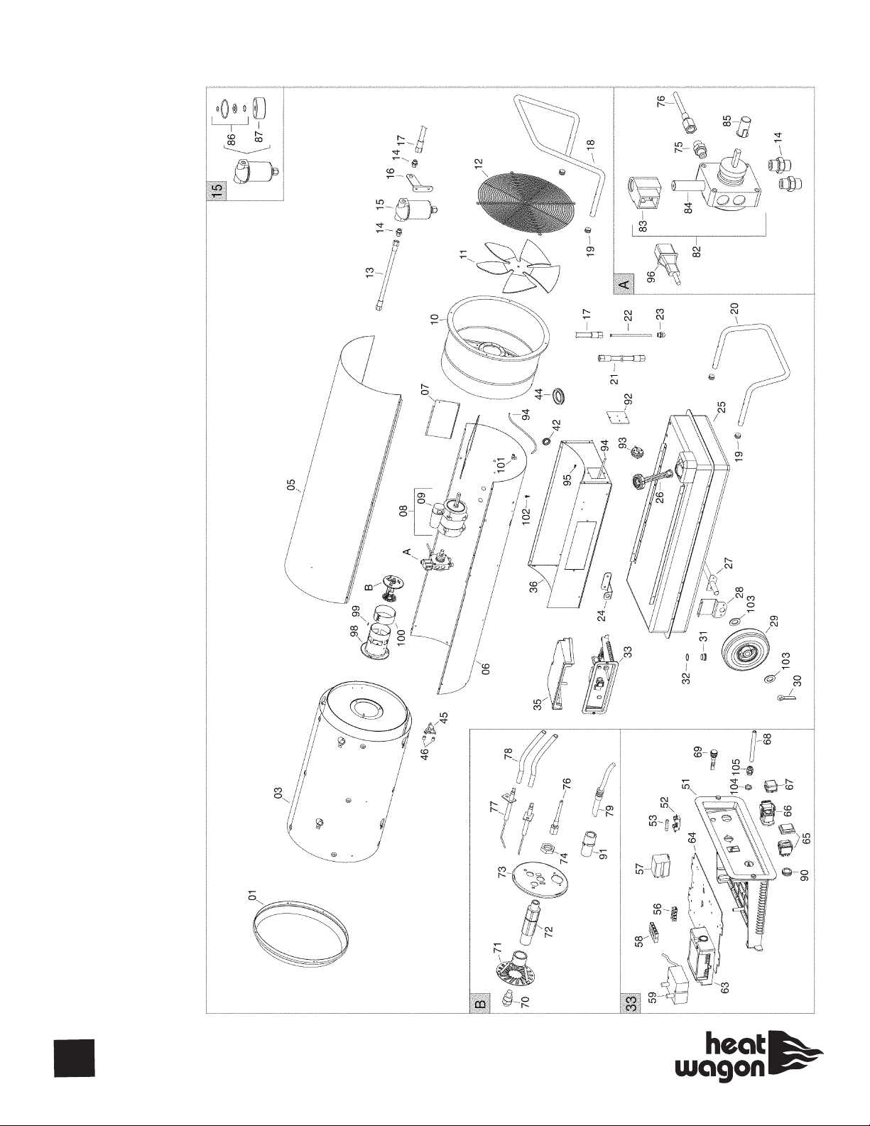
DF400
Breakdown
16
Page 17

DF400
Parts List
POS P/N DESCRIPTION
01 G06139-9010 Outlet cone
03 G06231 Combustion chamber
05 G06234-9010 Upper body
06 G06237-9010 Lower body
07 G06397 Air conveyor
AACO
08 E10704-110 Motor
09 E11249 Capacitor
SIMEL
08 E10772 Motor
09 E10772-1 Capacitor
10 G06239-9010 Air conveyor
11 T10215-B Fan
12 P30129 Inlet grill
13 I40330 Flex diesel pipe
14 I20104 Iron fitting
15 T20239 Diesel pre-heated filter
16 G06104-9005 Filter support bracket
17 I40329 Flex diesel pipe
18 P20176-9005 Handle
19 C30355 Pipe cap
20 P20177-9005 Support
21 I40331 Flex diesel pipe
22 I30696 Suction pipe
23 I30737 Brass fitting
24 G06068-9005 Power cord support
25 G06128-9005 Fuel tank
26 02AC508 Cap with level control
27 G06465-9005 Wheel axle
28 G06106-9005 Wheels axle support bracket
29 C10510 Wheel - Hard rubber
C10556 Wheel - Air filled
30 M20507 Cotter pin
31 I25020 Drain cap
32 C30375 O-ring
33 G00248 El. control box
35 P50127 Control box cover
36 G06411-9010 Base
42 C30323 Cable protection
44 C30372 Cable protection
45 E50102 Safety thermostat
46 G06072 Spacer
51 G06153 El. control box panel
52 E20508 Fuse holder
53 E10313 Fuse
56 E20319 Ground terminal board
57 E11125 Relay
POS P/N DESCRIPTION
58 E20305 Terminal board
59 E10930 H.T. Transformer
63 E40124 Flame control box
64 G06073 Support plate
65 E10102-P Switch
66 E20640 Thermostat plug
67 E20665 Thermostat plug cover
68 E30443 Power cord
E30443-1 Power cord - with fastener nut
69 E11030 Lamp
70 T20357 Nozzle
71 G01077 Diffuser ring
72 I33005 Nozzle support
73 G06228 Burner support disc
74 I31034 Brass lock nut
76 I40192 Micropipe
75 I20115 Iron fitting
77 E10215 Ignition electrode
78 G02078 H.T. Cable connect.
79 E50328 Photocell
82 T20411-1 Diesel pump
83 T20118 Solenoid coil
84 T20117 Solenoid valve body
AACO
85 E10514 Motor-pump coupling
SIMEL
85 E10698 Motor-pump coupling
86 T20241 Filter seal kit
87 T20242 Filter cartridge
90 E20418 Stop button protection
91 E50327 Photoresistor support
92 G06406-9010 Pressure switch support bracket
93 E50440 Pressure switch
94 I40335 Silicone pipe
95 I31131 Brass hose connection
96 T20442 Solenoid valve cable
98 G06249 Blast tube
99 E20671 Terminal board
100 G06183 Air adjustment shutter
101 I20325 Fitting
102 I31130 Brass hose connection
103 M20111 Washer
104 E20965 Cable fastener nut
105 E20964 Cable fastener
Optional Thermostat
THIDF Optional thermostat w/50’ cord
7979K62 4 pin plug insert
7979K68 4 pin plug cover
17
Page 18
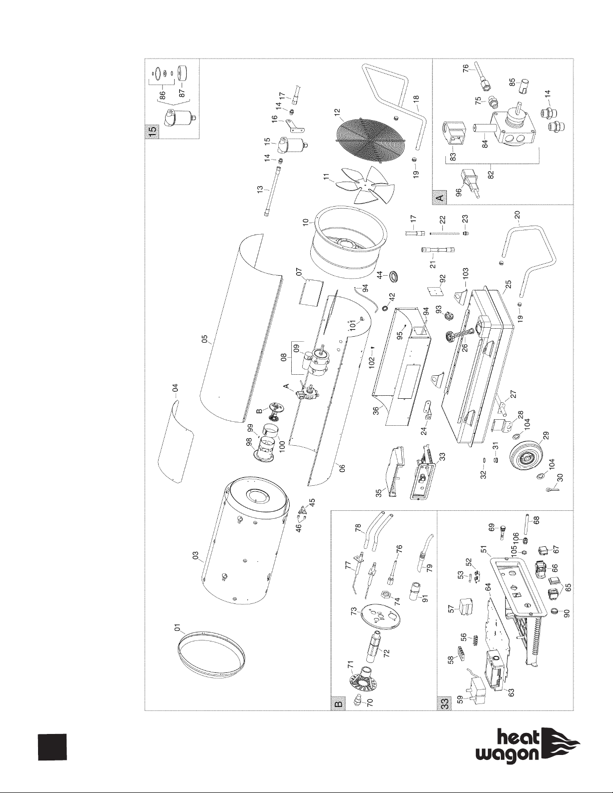
DF600
Breakdown
18
Page 19

DF600
Parts List
POS P/N DESCRIPTION
01 G06139-9010 Outlet cone
03 G06232 Combustion chamber
04 G06143-9010 Panel
05 G06235-9010 Upper body
06 G06238-9010 Lower body
07 G06397 Air conveyor
AACO
08 E10704-110 Motor
09 E11249 Capacitor
SIMEL
08 E10772 Motor
09 E10772-1 Capacitor
10 G06239-9010 Air conveyor
11 T10263 Fan
12 P30129 Inlet grill
13 I40330 Flex diesel pipe
14 I20104 Iron fitting
15 T20239 Diesel pre-heated filter
16 G06104-9005 Filter support bracket
17 I40329 Flex diesel pipe
18 P20176-9005 Handle
19 C30355 Pipe cap
20 P20180-9005 Support
21 I40331 Flex diesel pipe
22 I30698 Suction pipe
23 I30737 Brass fitting
24 G06068-9005 Power cord support
25 G06146-9005 Fuel tank
26 02AC510 Cap with level control
27 G06465-9005 Wheel axle
28 G06107-9005 Wheels axle support bracket
29 C10510 Wheel - Hard rubber
C10556 Wheel - Air filled
30 M20507 Cotter pin
31 I25020 Drain cap
32 C30375 O-ring
33 G00251 El. control box
35 P50127 Control box cover
36 G06411-9010 Base
42 C30323 Cable protection
44 C30372 Cable protection
45 E50102 Safety thermostat
46 G06072 Spacer
51 G06153 El. control box panel
52 E20508 Fuse holder
53 E10313 Fuse
56 E20319 Ground terminal board
57 E11125 Relay
POS P/N DESCRIPTION
58 E20305 Terminal board
59 E10917-2 H.T. Transformer
63 E40124 Flame control box
64 G06073 Support plate
65 E10102-P Switch
66 E20640 Thermostat plug
67 E20665 Thermostat plug cover
68 E30443 Power cord
E30443-1 Power cord - with fastener nut
69 E11030 Lamp
70 T20327 Nozzle
71 G07025 Diffuser ring
72 I33005 Nozzle support
73 G06229 Burner plate
74 I31034 Brass lock nut
75 I20115 Iron fitting
76 I40192 Micropipe
77 E10215 Ignition electrode
78 G02076 H.T. Cable connect.
79 E50328 Photocell
82 T20411-1 Diesel pump
83 T20118 Solenoid coil
84 T20117 Solenoid valve body
AACO
85 E10514 Motor-pump coupling
SIMEL
85 E10698 Motor-pump coupling
86 T20241 Filter seal kit
87 T20242 Filter cartridge
90 E20418 Stop button protection
91 E50327 Photoresistor support
92 G06406-9010 Pressure switch support bracket
93 E50441 Pressure switch
94 I40335 Silicone pipe
95 I31131 Brass hose connection
96 T20442 Solenoid valve cable
98 G06412 Blast tube
99 E20671 Terminal board
100 G06183 Air adjustment shutter
101 I20325 Fitting
102 I31130 Brass hose connection
103 02AC511 Lifting bracket
104 M20111 Washer
105 E20965 Cable fastener nut
106 E20964 Cable fastener
Optional Thermostat
THIDF Optional thermostat w/50’ cord
7979K62 4 pin plug insert
7979K68 4 pin plug cover
19
Page 20
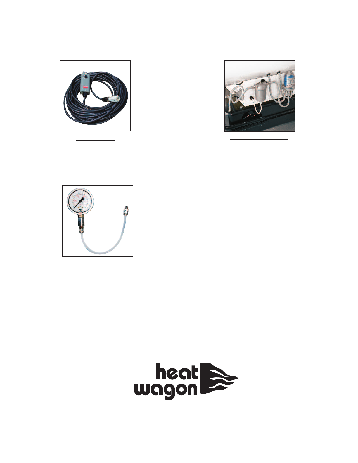
Accessories
THERMOSTAT
#THIDF
FUEL PRESSURE GAUGE
#BIE99AM003
EXTERNAL FUEL KIT
(allows access to
external fuel source)
#TK400
342 N. Co. Rd. 400 East • Valparaiso, IN 46383
219-464-8818 • 888-432-8924 • Fax 800-255-7985
www.heatwagon.com
 Loading...