

C US
342 N. Co. Rd. 400 East
Valparaiso, IN 46383
219-464-8818 • Fax 219-462-7985
www.heatwagon.com
Installation and Maintenance Manual
Please retain this manual for future reference.
HVF180/HVF300
Construction
Heaters
NRTL
ANSI Z83.7
CONST. HTR
Revision 10-12
For your safety: Do not use this heater in
a space where gasoline or other liquids
having flammable vapors are stored.
CONSTRUCTION HEATER GENERAL HAZARD WARNING:
F
ailure to comply with the precautions and instructions provided with this heater,
can result in death, serious bodily injury and property loss or damage from hazards
of fire, explosion, burn, asphyxiation, carbon monoxide poisoning, and/or electrical
shock.
Only persons who can understand and follow the instructions should use or service
this heater.
If you need assistance or heater information such as an instruction manual, labels,
etc., contact your local Heat Wagon dealer or the manufacturer.
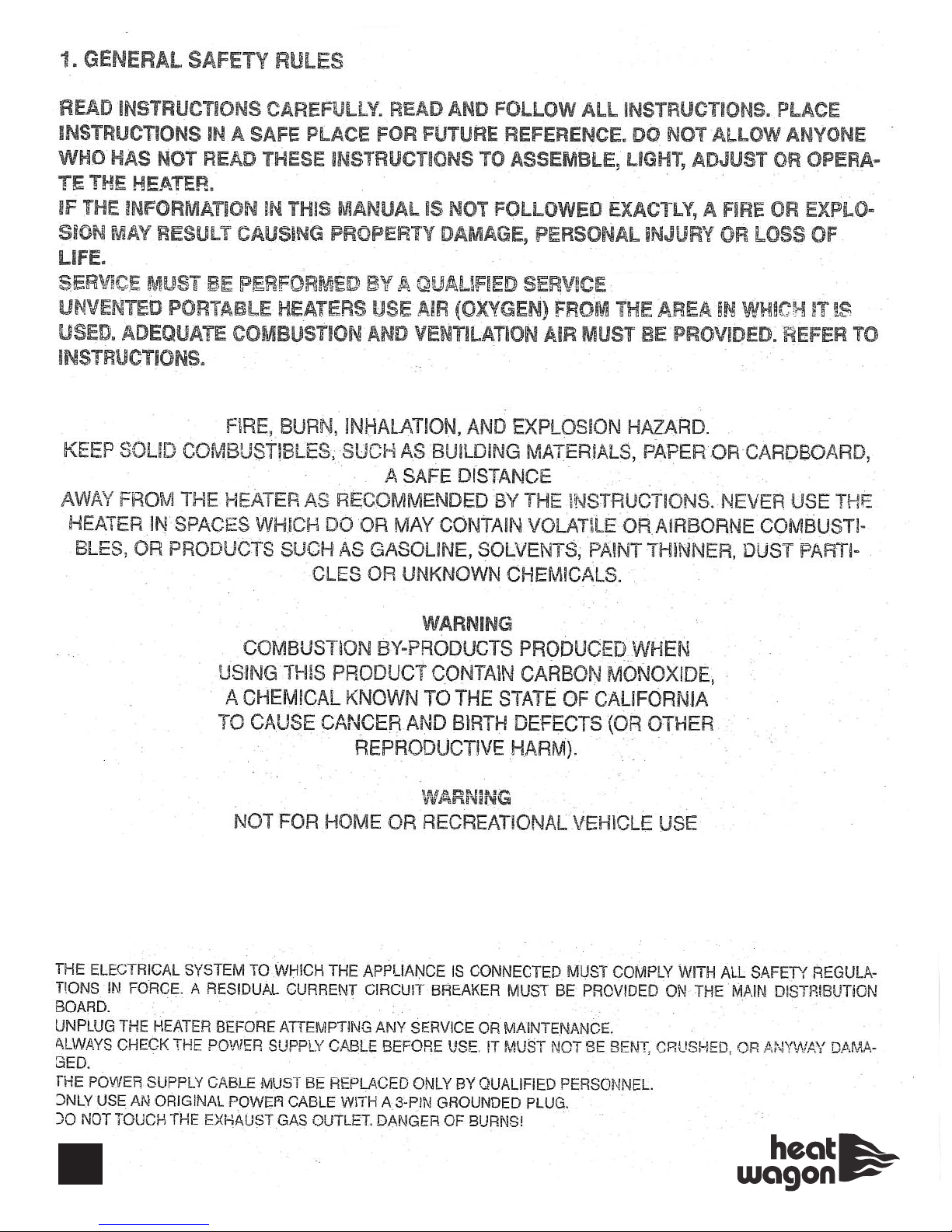
W A R N I N G
Fire, burn, inhalation, and explosion hazard. Keep solid combustibles, such as building materials, paper or cardboard, a safe distance away from the heater as recommended by the instructions. Never use the heater in spaces which do or may contain
volatile or airborne combustibles, or products such as gasoline, solvents, paint thinner, dust particles or unknown chemicals.
Not for home or recreational vehicle use!
Heater is not intended for use in pest remediation.
We cannot anticipate every use which may be made for our heaters. CHECK WITH YOUR
LOCAL FIRE SAFETY AUTHORITY IF YOU HAVE QUESTIONS ABOUT LOCAL REGULATIONS.
Other standards govern the use of fuel gases and heat producing products in specific applications. Your local authority can advise you about these.
FOR YOUR SAFETY
DO NOT USE THIS HEATER IN A SPACE WHERE GASOLINE OR OTHER LIQUIDS HAVING FLAMMABLE VAPORS ARE STORED OR USED.

Installation and Maintenance Manual
Model HVF180-HVF300
Construction Heater
Table of Contents:
Page
Safety and Caution . . . . . . . . . . . . . . . . . . . . . . . . . . . . . . . . . . . . . . . . . . .3
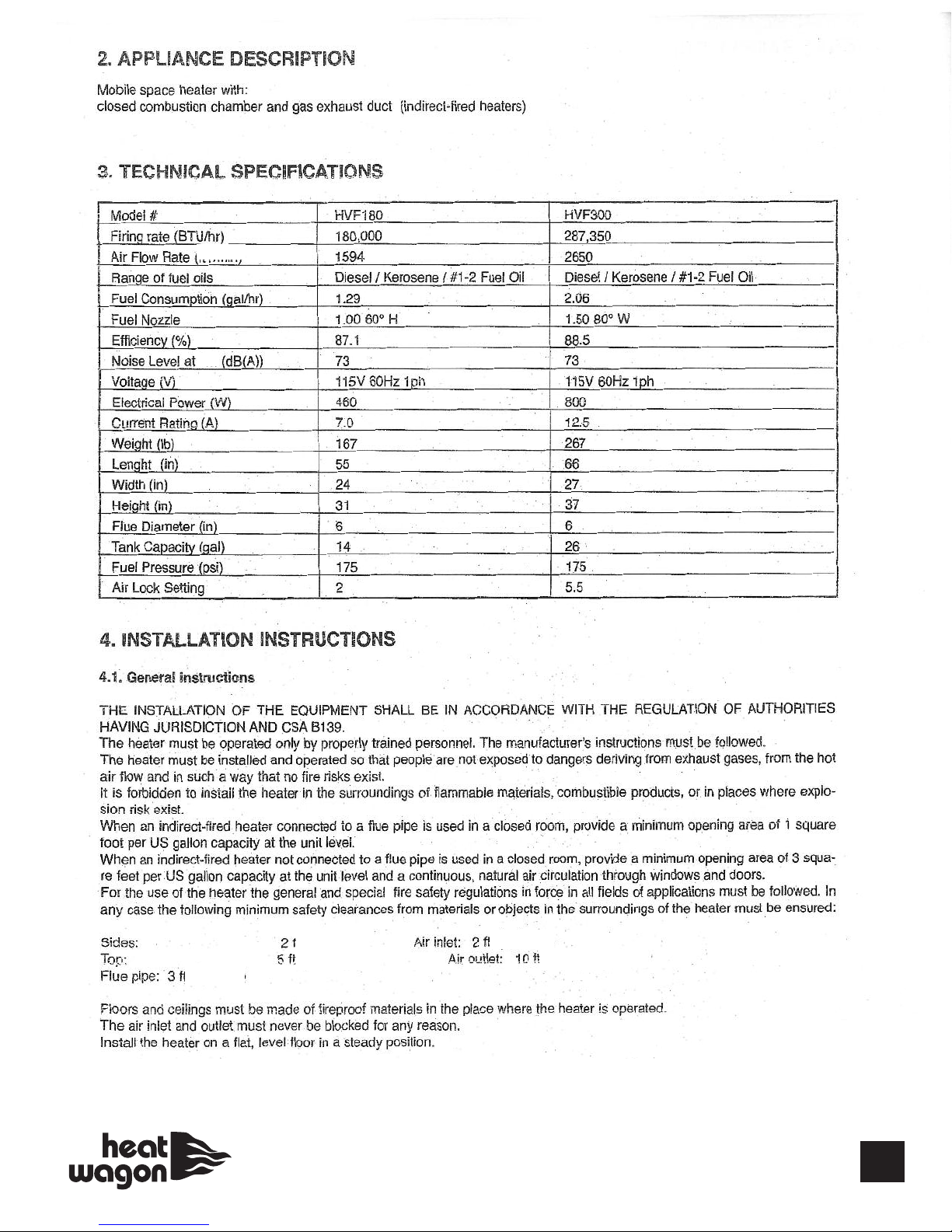
Specifications . . . . . . . . . . . . . . . . . . . . . . . . . . . . . . . . . . . . . . . . . . . . . . .4
Installation . . . . . . . . . . . . . . . . . . . . . . . . . . . . . . . . . . . . . . . . . . . . . . . . .4
Operating Instructions . . . . . . . . . . . . . . . . . . . . . . . . . . . . . . . . . . . . . . . .7
Maintenance . . . . . . . . . . . . . . . . . . . . . . . . . . . . . . . . . . . . . . . . . . . . . . . .8
Troubleshooting . . . . . . . . . . . . . . . . . . . . . . . . . . . . . . . . . . . . . . . . . . . . .8
Wiring Diagrams . . . . . . . . . . . . . . . . . . . . . . . . . . . . . . . . . . . . . . . . . . . .9
Illustrated Parts Breakdown . . . . . . . . . . . . . . . . . . . . . . . . . . . . . . . .10-11
Advance Troubleshooting . . . . . . . . . . . . . . . . . . . . . . . . . . . . . . . . .12-17
Chimney/Exhaust Set-up . . . . . . . . . . . . . . . . . . . . . . . . . . . . . . . . . . . . .18
Accessories . . . . . . . . . . . . . . . . . . . . . . . . . . . . . . . . . . . . . . . . . . . . . . . .19
WARRANTY
All new Heat Wagon and Sure Flame heaters and fans are guaranteed against defective materials and workmanship for one (1) year from invoice date.
Warranty repairs may be made only by an authorized, trained and certified Heat Wagon dealer. Warranty
repairs by other entities will not be considered. Warranty claims must include model number and serial
number.
LIMITATIONS
Warrant claims for service parts (wear parts) such as spark plugs, igniters, flame rods will not be allowed.
Diagnostic parts such as voltage meters and pressure gauges are not warrantable.
Evidence of improper fuel usage, fuel pressures outside of manufacturer’s specification, poor fuel quality,
and improper electric power, misapplication or evidence of abuse may be cause for rejection of warranty
claims.
Travel time, mileage and shipping charges will not be allowed. Minor adjustments of heaters are dealers’
responsibility. Defective parts must be tagged and held for possible return to the factory for 60 days from
date of repair. The factory will provide a return goods authorization, (RGA) for defective parts to be
returned.
No warranty will be allowed for parts not purchased from Heat Wagon.
342 N. Co. Rd. 400 East • Valparaiso, IN 46383
219-464-8818 • 888-432-8924 • Fax 800-255-7985
www.heatwagon.com
TECHNICIAN.
4
(CFM)
6 ft.
5
Indirect Oil Theory of Operation
When the on/off power switch is turned on, power is sent to a power indicator light on the control panel. Power is also
received by the control board. The control board sends power out to a thermostat “socket”. The socket must have a
“jumper cap” or a remote thermostat plugged into the socket. The heater has a heating element in the fuel filter, the element will now receive power from the control board, and begin pre-heating the fuel.
When the thermostat jumper cap is in place, or the remote thermostat is turned up to call for heat, the control board will
begin the start up sequence. During the first step of start up called the purge cycle, the control board powers the motor
and transformer for a short period of approximately ten seconds. The turning motor provides airflow and the transformer
provides spark to light and burn off any residual fuel remaining from prior operation. At this time the fuel solenoid valve
receives no power and remains closed. All fuel pumped is sent back to the fuel tank thru the fuel pump’s return line.
During this purge cycle the photocell which is connected to the control board looks for the presence of flame in the combustion chamber. If flame is detected during the purge cycle, the control board “locks out” or removes power from all
components. The heater is equipped with an air proving switch, air from the turning fan blade must close the switch,
otherwise lock out will occur.
Once the purge cycle is completed successfully, the ignition cycle can begin. The control board now sends power to the
fuel solenoid valve. The valve opens allowing fuel to flow thru to the nozzle. The photocell must now detect flame within
several seconds or the control board will lock out. If flame is detected briefly and then lost, the purge and ignition cycles
are repeated once more and if ignition is not achieved, lock out occurs. Control board removes power to the transformer
a short time after ignition is achieved. If for any reason ignition is lost, the control board will remove power to the fuel
solenoid valve and the purge and ignition cycles will begin. Once ignition is established the thermostat will cycle the
heater on and off as needed.
If lock out occurs the reset button will trip. The heaters need a thirty second wait before the reset will function again.
6

ote: Heater will not operate without socket cover or thermostat.
N
grounded
duct restriction
before using the heater again. Have the
heater inspected by a qualified technician
if required. See point above for resetting.
)
Go to page 18 for proper
chimney/exhaust pipe
installation.
5.3 Heat Ducting
There are a few things to keep in mind when ducting a heater.
First, ensure that the duct is rated high enough for the heater’s
discharge temperature. Second, make sure that the duct I.D. is
equal to the diameter of the heater discharge. A larger I.D.
solid wall or wire duct (no lay-flat) duct can be used. When
dealing with duct length, remember that the owner’s manual
will list a MAXIMUM duct length and this length must be
adhered to at all times! The maximum duct length is the total
length straight out from the nose of the heater. As a general
rule of thumb, for every bend in the duct, it cuts the maximum
length allowed in half. Also, to achieve the highest heating efficiency and to alleviate static pressure issues, keep the elbows
and bends down to the absolute minimum.
5.4 Shut Down.
Set switch to “OFF” to shut the flame off. The fan
will go on rotating for about 1 min 45 sec to cool
the heater down. The fan motor will automatically
stop at the end of the aftercooling time, then the
unit can be disconnected from mains.
Never disconnect the supply plug to stop the
heater while in operation. The heat accumulation
could damage the components: allow the cooling
sequence to be carried out.
5.5 Outdoor use
If the heater is used outdoors, follow the general
installation instructions detailed above (see point
4). Moreover, the heater should not be directly
exposed to the weather. Provide proper protection from rain, snow, wind, humidity etc. the use
of a vent cap is also required.
7

(Fan does not run)
Contact Heat Wagon
Contact Heat Wagon
/Lack of fuel
Air switch fault
8
/Check solenoid valve at pump & check supply hose for leaks
Remove ducting/check voltage at control board

*brown
*blue
*blue
*For Digital Thermostat
*brown
Digital Thermostat
(On/Off Switch)
Terminal M3
Terminal M10
Terminal M9
9

HVF180 Parts List
Pump Pressure Setting
175 PSI
Key No. Part No. Description
1 1087008133 FAN
2 1040012900 MOTOR
3 1001001300 JOINT
4 1049000419 CAPACITOR
5 1089007200 COIL
6 1043004500 CABLE + CONNECTOR
7 1076004300 MICROHOSE
8 1067004100 FITTING
9 1089007100 PUMP
10 1018002900 WASHER
11 1066001300 FITTING
12 1067009100 OGIVE
13 1066001600 FITTING
14 1078000600 BACKFLOW HOSE
15 1078000100 INFLOW HOSE
16 1050001000 FLAME SENSOR
17 1039043600 HT CABLE
18 1094135533 BURNER HEAD
19 1088012100 NOZZLE
20 1030002100 ELECTRODE
21 1001017700 COVER
22 1033004600 TRANSFORMER
23 1041001700 LAMP
24 1032001700 ON/OFF SWITCH
25 1002002600 CAP
26 CAVAL#US10400USAP2 POWER SUPPLY CABLE
27 1035001800 FUSE
28 1002002855 CAP
29 1032005500 RESET PUSHBUTTON
30 1052001800 SOCKET CAP
31 1043000400 SOCKET BODY
32 1043000600 SOCKET CASING
33 1001017200 CONTROL PANEL
34 1001015680 SPACER
35 1047004600 BURNER CONTROL
36 1078000300 SUCTION HOSE
37 1066001700 FITTING
38 1067009100 OGIVE
39 1017002800 NUT
40 1094134900 FILTER BRACKET
41 1066001500 FITTING
42 1086000800 OIL FILTER
Key No. Part No. Description
42/1 1135000500 COVER
42/2 1002004200 O-RING
42/3 1002005100 GASKET
42/4 1086002800 CARTRIDGE
42/5 1002005200 O-RING
42/6 1052004900 HEATING ELEMENT
42/7 1135000600 FILTER GLASS
43 1066001300 FITTING
44 1067009100 OGIVE
45 1066001600 FITTING
46 1066001600 FITTING
47 1067009100 OGIVE
48 1066001200 SUCTION FITTING
49 1095011800 HANDLE
50 1090007533 GUARD
51 CONVGEN#MIR05536 AIR INLET
52 PORTISP#TOMM436 INSPECTION COVER
53 COPGEN#MIR05536 UPPER SHELL
54 1005000100 TANK CAP
55 1002002000 GASKET
56 1002002100 GASKET
57 1086001000 FILLING FILTER
58 1005000900 HANDLE CAP
59 1094046500 TANK SUPPORT
60 1023001500 SPRING
61 1005002000 WHEEL CAP
62 1022000300 SEEGER RING
63 1004001300 WHEEL
64 1094134100 AXLE
65 1094135733 AIR LOCK
66 1095011233 CHAMBER INLET
67 CAMGEN#MIR055 COMBUSTION CHAMBER
68 PROCAMGEN#MIR5H CHAMBER SHIELD
69 CONOMIR#055A36 AIR OUTLET
70 1094138733 FLUE COLLAR
71 1017002200 FIXING CLIP
72 CRPGEN#MIR18036 LOWER SHELL
73 SERBGEN#MU20 TANK
74 1046001500 AIR PRESSURE SWITCH
75 1094171300 PLATE
76 1080002600 AIR HOSE
77 1046001036 HOSE FITTING
NOT SHOWN
1067007000 DRAIN PLUG FOR TANK
1002006000 O-RING KIT FOR FILTER
Includes (42/2, 42/3, 42/5)
10

HVF300 Parts List
Pump Pressure Setting
175 PSI
Key No. Part No. Description
1 1087008233 FAN
2 1040013000 MOTOR
3 1001017400 JOINT
4 1049002800 CAPACITOR
5 1089007200 COIL
6 1043004500 CABLE + CONNECTOR
7 1076004300 MICROHOSE
8 1067004100 FITTING
9 1089006100 PUMP
10 1018002900 WASHER
11 1066001300 FITTING
12 1067009100 OGIVE
13 1066001600 FITTING
14 1078000500 BACKFLOW HOSE
15 1078000100 INFLOW HOSE
16 1050001000 FLAME SENSOR
17 1039043600 HT CABLE
18 1094135633 BURNER HEAD
19 1088014000 NOZZLE
20 1030002100 ELECTRODE
21 1001017700 COVER
22 1033004600 TRANSFORMER
23 1041001700 LAMP
24 1032001700 ON/OFF SWITCH
25 1002002600 CAP
26 CAVAL#US10400USAP2 POWER SUPPLY CABLE
27 1035000800 FUSE
28 1002002855 CAP
29 1032005500 RESET PUSHBUTTON
30 1052001800 SOCKET CAP
31 1043000400 SOCKET BODY
32 1043000600 SOCKET CASING
33 1001017200 CONTROL PANEL
34 1001015680 SPACER
35 1047004600 BURNER CONTROL
36 1078001000 SUCTION HOSE
37 1066001700 FITTING
38 1067009100 OGIVE
39 1017002800 NUT
40 1094134900 FILTER BRACKET
41 1066001500 FITTING
42 1086000800 OIL FILTER
42/1 1135000500 COVER
Key No. Part No. Description
42/2 1002004200 O-RING
42/3 1002005100 GASKET
42/4 1086002800 CARTRIDGE
42/5 1002005200 O-RING
42/6 1052004900 HEATING ELEMENT
42/7 1135000600 FILTER GLASS
43 1066001300 FITTING
44 1067009100 OGIVE
45 1066001600 FITTING
46 1066001600 FITTING
47 1067009100 OGIVE
48 1066001200 SUCTION FITTING
49 1095011700 HANDLE
50 1090007633 GUARD
51 CONVGEN#MIR08536 AIR INLET
52 PORTISP#TOMG436 INSPECTION COVER
53 COPGEN#MIR08536 UPPER SHELL
54 1005000100 TANK CAP
55 1002002000 GASKET
56 1002002100 GASKET
57 1086001000 FILLING FILTER
58 1005000900 HANDLE CAP
59 1094141600 TANK SUPPORT
60 1023001500 SPRING
61 1005002000 WHEEL CAP
62 1022000300 SEEGER RING
63 1004001300 WHEEL
64 1094141500 AXLE
65 1094135733 AIR LOCK
66 1095011333 CHAMBER INLET
67 CAMGEN#MIR085 COMBUSTION CHAMBER
68 PROCAMGEN#MIR8H CHAMBER SHIELD
69 CONOMIR#085A36 AIR OUTLET
70 1094138733 FLUE COLLAR
71 1017002200 FIXING CLIP
72 CRPGEN#MIR08536 LOWER SHELL
73 SERBGEN#G420 TANK
74 1046001500 AIR PRESSURE SWITCH
75 1094171300 PLATE
76 1080002600 AIR HOSE
77 1046001036 HOSE FITTING
NOT SHOWN
1067007000 DRAIN PLUG FOR TANK
1002006000 O-RING KIT FOR FILTER
Includes (42/2, 42/3, 42/5)
11

ADVANCED TROUBLESHOOTING
otor and transformer do not operate.
M
Causes:
1. Incorrect or low voltage supplied to the heater.
2. Fuse in heater is blown.
. Thermostat defective, or not turned up to call for heat.
3
4. Thermostat jumper cap not in place.
5. Control board is defective.
6. Reset button has not been reset.
Solutions:
1. Incorrect or low voltage supplied to the heater. Most indirect oil heaters require a minimum of 108 volts to operate properly. A multi-meter set to
measure volts can be used to check the amount of voltage at the end of the extension cord(s). If the measured voltage is too low, the length of the
extension cord (s) must be shortened or a thicker gauge extension cord must be used.
2. Fuse in heater is blown. Locate and remove the in-line fuse of the heater. Set a multi-meter to measure ohms of resistance. Place a multi-meter
probe on each end of the fuse. The multi-meter should read zero ohms (continuity) or the fuse is blown. If a new fuse blows immediately, check for
possible causes. Check for incorrect voltage to the heater. Make sure the total amperage draw of all equipment running on the circuit is not too
great. If the supplied voltage and total amperage draw are correct, check the wiring in the heater for correctness and possible shorts.
3. Thermostat is defective or not turned up to call for heat. Turn the thermostat up to the highest possible setting and try to start the heater. Next
set a multi-meter to measure voltage coming out of the thermostat. If approximately 120 volts is not measured, the thermostat is defective.
4. Thermostat jumper cap not in place. Indirect oil heaters have a female socket used to attach an optional remote thermostat. If the remote
thermostat is not being used, a jumper cap or “plug” must be inserted into the female socket to complete a voltage circuit, or the heater will not run.
5. Control board is defective. Using a multi-meter set for volts, check the hot and neutral wires which bring voltage into the control board. If proper
voltage is reaching the board then the control board is defective.
6. Reset button has not been reset. Push the reset button and try to start the heater.
Motor does not start, but ignition spark is present
Causes:
1. Control board is defective.
2. Motor is defective.
3. Motor start capacitor is defective.
4. Fuel pump seized
Solutions:
1. Control board is defective.Locate the terminals of the control board that connect to the motor wires. Use a multi-meter set to read voltage and
check for approximately 120 volts to the motor when the heater is turned on. If no voltage is observed the control board is defective.
2. Motor is defective. If the control board and the motor start capacitor check ok and the fuel pump is not seized, the motor is defective.
3. Motor start capacitor is defective. The capacitor may be tested using a multi-meter set to the lowest possible ohm range. First “short” the capaci-
tor by momentarily placing a screwdriver across the two capacitor terminals. Then place the multi-meter probes on the two capacitor terminals. The
multi-meter should read close to zero ohms (continuity) first, then slowly move to infinity on the multi-meter. If not then the capacitor is defective.
4. Fuel pump seized. With the heater unplugged, stand behind the heater and attempt to turn the fan blade clockwise by hand. If the fan blade is
difficult to turn, undo the connection between the motor shaft and the pump shaft. Attempt turning the fan blade again. If the motor now turns freely,
the pump has seized up. If the fan blade is still difficult to turn, the motor is defective.
12

Motor runs, spark is present, but there is no fuel spray
auses:
C
1. Spray nozzle clogged.
2. Fuel pump is defective/or broken pump coupling
3. Air entering the fuel pump thru the inlet line.
4. Solenoid valve is defective.
. Control board is defective.
5
6. Fuel filter is dirty.
7. Safety thermostat defective or tripped or improper ducting.
8. Air proving switch defective.
9. Fuel gel.
Solutions:
1. Spray nozzle clogged. Remove and inspect the spray nozzle. Clean or replace as needed. Do not clean the nozzle orifice with anything metal
as this may enlarge the orifice.
2. Fuel pump is defective. The output pressure of the fuel pump can be checked by placing a high pressure fuel gauge into the gauge port of the
fuel pump. Use a gauge with enough capacity to measure the high pressure your particular heater can produce. Use the adjustment on the pump
to set the pump pressure to the manufacturer’s specification. If you do not have a fuel gauge, you may slightly loosen the pump’s output line connection and place a rag there. Run the heater briefly and see if fuel reaches the rag. If no fuel is pumped, check the connection between the motor
and the fuel pump to make sure the motor can turn the pump. Also check the external and internal fuel filters for blockage, and clean or replace if
necessary. The fuel pumps internal filter is usually located where the fuel inlet line enters the pump. Check to make sure motor is rotating pump.
3. Air entering the fuel pump thru the fuel inlet line. If air enters the pump it will lose its prime and will not maintain adequate pump pressure. First
make sure all fittings, including the fuel filter on the inlet line are tight. If you still suspect air is entering the pump, start eliminating portions of the
inlet line until the air leak is found. Start this process at the fuel tank end of the inlet line. It may be necessary to draw fuel from a small container
rather than the fuel tank.
4. Solenoid valve is defective. Use a multi-meter set to measure volts. Check for approximately 120 volts at the ends of the two wires that carry
voltage to the solenoid valve. If proper voltage is read, try cleaning the valve if it is dirty. If the valve will not open fully to allow fuel spray, the solenoid valve is defective. If proper voltage is not read, check for voltage on the control board terminals that the solenoid valve wires connect to. If
proper voltage is read, the solenoid valve wires are defective. If voltage is not read on the board terminals, the control board is defective.
5. Control board is defective. Use a multi-meter set to measure voltage. Check for proper voltage on the two board terminals that the solenoid
valve wires connect to. If proper voltage is read, the control board is ok. If proper voltage is not read, the control board is defective.
6. Fuel filter dirty. Check the external and internal fuel filters and clean or replace as necessary. Most fuel pumps contain an internal fuel filter
located where the inlet line enters the fuel pump.
7. Safety thermostat defective or tripped. Also called overheat switch. Some indirect oil heaters have a safety thermostat wired between the con-
trol board and the solenoid valve. If the heater becomes too hot this normally closed switch will open and interrupt power to the solenoid valve.
Use a multi-meter set to measure ohms. Place the multi-meter probes on the two male terminals of the safety thermostat. If the multi-meter shows
infinity (no continuity) the safety thermostat is defective. If the switch opens up before the heater becomes hot, the safety thermostat is defective.
8. Air proving switch is defective. Try to start the heater without ducting. Indirect oil heaters have an air proving switch wired between the control
board and the solenoid valve. The air proving switch is normally open and requires air from the turning fan blade to close the switch and send
power to the solenoid valve. Set a multi-meter to measure voltage. With the fan blade turning, check for voltage coming out of the air proving
switch to the solenoid valve. If no voltage is read, next check for voltage at the control board terminals out to the air proving switch. If voltage at the
control board is read, the air proving switch is defective. If no voltage is read at the board, the control board is defective.
9. Examine condition of fuel in filter and tank. Diesel fuel may “gel” below 30ºF. See fuel blend guide, page 18. Plug in heater and allow
preheater to warm fuel (15 min).
13

Motor runs, fuel sprays, but no spark is observed
Causes:
1. Electrodes damaged or gapped incorrectly.
2. Transformer defective.
3. Control board defective.
Solutions:
1. Electrodes damaged or gapped incorrectly. Inspect the electrode tips for melting. Make sure there are no cracks in the porcelain insulation.
Check the electrodes with the manufacturer’s specifications for gapping and spacing. Adjust or replace the electrodes as needed.
2. Transformer defective. Transformers require a ground connection to function properly. Check the transformer’s ground wire or mounting tabs for
a good ground connection. Use a multi-meter set to measure voltage. Check the voltage in to the transformer from the control board for approximately 120 volts. Do not attempt to measure the transformer’s output voltage with an ordinary multi-meter. The transformer may also be bench
tested for proper output arc.
3. Control board defective. Use a multi-meter set to measure voltage. Take a voltage reading on the control board terminals that send input power
to the transformer. If proper voltage is not present, the control board is defective.
Motor runs, fuel sprays, spark is present, but heater will not ignite
Causes:
1. Pump pressure incorrect.
2. Electrodes damaged or gapped incorrectly.
3. Nozzle dirty or worn.
4. Air damper setting is incorrect.
5. Transformer output is weak.
6. Ducting is improper.
7. Venting is improper.
8. Fuel contains water or contaminants.
Solutions:
1. Pump pressure incorrect. Using a high pressure fuel gauge, check the output pressure of the fuel pump. If necessary, use the pump’s adjust-
ment to set the pump pressure to the manufacturer’s specifications.
2. Electrodes damaged or gapped incorrectly. Inspect the electrode tips for melting. Make sure there are no cracks in the porcelain insulation.
Check the electrodes with the manufacturers specifications for gapping and spacing. Adjust or replace the electrodes as needed.
3. Nozzle dirty or worn. Clean the nozzle using compressed air. Never use anything metal to clean the nozzle as this may enlarge the orifice. With
enough use, fuel traveling under high pressure thru the nozzle orifice can enlarge the orifice. This is especially true when diesel fuel is used. Clean
or replace the nozzle as needed.
4. Air damper setting is incorrect. Use the manufacturers specifications for the air damper setting and adjust as needed.
5. Transformer output is weak. Remove the transformer and perform a bench test.
6. Ducting is improper. Follow the manufacturer’s recommendations concerning maximum duct length and diameter.
7. Venting is improper. Follow the manufacturer’s guidelines for venting.
8. Fuel contains water or contaminants. Visually inspect the fuel in the tank for water bubbles or contaminants. Drain, flush, and re-fill tank as
needed.
14

eater ignites, runs less than one minute and shuts down
H
Causes:
1. Photocell is dirty, misaligned or defective.
2. Control board is defective.
. Fuel pump defective.
3
4. Fuel filter dirty.
Solutions:
1. Photocell is dirty, misaligned or defective. Check that the photocell is aimed correctly and is free of dirt. If necessary, clean the photocell “eye”
with a soft, dry cloth. Unfortunately no test exists for the photocell. Attempting to “jumper out” the photocell will not test the function. You must
either replace the photocell or borrow a known functioning photocell from an identical heater.
2. Control board is defective. If the heater’s spray and spark are correct, the photocell and control board must work together to recognize the com-
bustion flame has become established. Therefore if a new photocell does not correct this symptom, the control board is defective.
3. Fuel pump is defective. If the fuel pump will not achieve or maintain proper output pressure, the fuel pump is defective. Check the pump’s output
pressure with a gauge.
4. Fuel filter dirty. Inspect the internal and external fuel filters and clean or replace as needed.
Heater ignites, runs several minutes, then shuts down.
Causes:
1. Fuel pump is defective.
2. Solenoid valve is defective.
3. Overheat thermostat is defective.
4. Ducting is improper.
5. Venting is improper.
6. Nozzle is dirty.
7. Fuel filter is dirty.
8. Control board is defective.
9. Fuel contains water or contaminants.
Solutions:
1. Fuel pump is defective. If the fuel pump will not achieve or maintain proper output pressure, the pump is defective. Check the fuel pump output
pressure with a gauge.
2. Solenoid valve is defective. Use a multi-meter set to measure voltage. Check for proper voltage at the solenoid valve. If proper voltage is read
and the solenoid valve will not stay open and allow fuel spray, the solenoid valve is defective.
3. Overheat thermostat is defective. Also called a safety thermostat or limit switch. Some heaters are equipped with this. Set a multi-meter to mea-
sure ohms of resistance. Perform this test immediately after the heater shuts down and the overheat thermostat is still hot. Place the multi-meter
probes on the two male terminals of the safety thermostat. If the multi-meter reads infinity (no continuity) the safety thermostat is defective.
Remember that if the heater is over firing due to high pump pressure, worn nozzle, or is improperly ducted or vented, the safety thermostat will
heat enough to shut the heater off.
4. Ducting is improper. Always follow the manufacturer’s recommendations
regarding maximum duct length and diameter. Failure to do so can result in heat building up in the heater until the safety thermostat contacts open
and shut the heater off.
15

5. Venting is improper. Follow the manufacturer’s recommendations concerning proper venting. Failure to do so can result in heat building up in the
heater until the safety thermostat contacts open and shut the heater off.
. Nozzle is dirty. If dirt reaches the nozzle, the spray can be adversely affected and cause a shut down. If possible observe the spray pattern and
6
clean the nozzle as needed.
7. Fuel filter dirty. Check the internal and external fuel filters. Clean or replace as needed.
8. Control board is defective. For the heater to function, the control board must send proper voltage to three components: motor, transformer and
solenoid valve. Using a multi-meter set to measure voltage, check the appropriate control board terminals for proper voltage out to these three
components. If proper voltage to any of these three components is not observed, the control board is defective.
9. Fuel contains water or contaminants. Visually inspect the fuel in the tank for water bubbles or contaminants. Drain, flush, and re-fill as needed.
Heater ignites, but combustion is poor or uneven
Causes:
1. Fuel pump pressure is incorrect.
2. Nozzle dirty or worn.
3. Electrodes damaged or gapped incorrectly.
4. Fuel filter is dirty.
5. Air damper setting incorrect.
6. Whirl disk dirty or mis-aligned.
7. Ducting is improper.
8. Venting is improper.
9. Fuel contains water or contaminants.
Solutions:
1. Fuel pump pressure is incorrect. The output pressure of the fuel pump can be checked by placing a high pressure fuel gauge into the gauge port
of the fuel pump. Use a gauge with enough capacity to measure the high pressure your particular heater can produce. Use the adjustment on the
pump to set the pump pressure to the manufacturer’s specifications.
2. Nozzle dirty or worn. Clean the nozzle using compressed air. Never use anything metal to clean the nozzle as this may enlarge the orifice. With
enough use, fuel traveling under high pressure thru the nozzle orifice can enlarge the orifice. This is especially true when diesel fuel is used. Clean
or replace the nozzle as needed.
3. Electrodes damaged or gapped incorrectly. Inspect the electrode tips for melting. Make sure there are no cracks in the porcelain insulation.
Check the electrodes with the manufacturer’s specifications for gapping and spacing. Adjust or replace the electrodes as needed (page 5/17).
4. Fuel filter is dirty. Inspect the internal and external fuel filters and clean or replace as needed.
5. Air damper setting incorrect. Use the manufacturer’s specifications for the air damper setting and adjust as needed. (see Diagram B, page 17)
6. Whirl disk dirty or mis-aligned. Inspect the whirl disk and clean if necessary. If the disk is warped or mis-aligned, replace or adjust as needed.
7. Ducting is improper. Follow the manufacturer’s recommendations concerning maximum duct length and diameter.
8. Venting is improper. Follow the manufacturer’s guidelines for venting.
9. Fuel contains water or contaminants. Visually inspect the fuel in the tank for water or contaminants. Drain, flush, and re-fill tank as needed.
16

Heater ignites but flame is excessive
Causes:
. Fuel pump pressure is too high.
1
2. Nozzle is worn.
3. Incorrect fuel.
Solutions:
1. Fuel pump pressure is too high. Attach a high pressure fuel gauge to the fuel pump and check the pump pressure. Adjust the pressure to the
manufacturer’s specifications with the adjustment on the fuel pump.
2. Nozzle is worn. With enough use, the impurities in the fuel traveling under high pressure thru the nozzle orifice can enlarge the orifice. This is
especially true when diesel fuel is used. A worn nozzle can cause the heater to run “rich” and possibly over fire the heater enough to activate the
safety thermostat and cause a shutdown. Replace after 400 hours of operation.
3. Incorrect fuel. Only use the manufacturer’s recommended fuels. Never use gasoline, paint thinner, solvents, or other flammable liquids. If you
suspect the fuel is incorrect, drain, flush and re-fill the tank with proper fuel.
3
Diagram B
17

Chimney/Exhaust Set-Up
9 ft.
30 ft.
15 ft.
3 ft.
18
12 ft.

Accessories
HVF180 - #WD1225
12” Diameter, 25’ Long
HVF300 - #WD1825
18” Diameter, 25’ Long
FUEL PRESSURE GAUGE
#BIE99AM003
DUCTING
FLUE STACK
#EF1
342 N. Co. Rd. 400 East
Valparaiso, IN 46383
219-464-8818 • Fax 219-462-7985
www.heatwagon.com
DUCT ADAPTER
HVF180 - #AR180
HVF300 - #AR300
THERMOSTAT
#THIDF
19
 Loading...