

Heat Wagon HVF180, HVF300 Installation And Maintenance Manual
C US
342 N. Co. Rd. 400 East
Valparaiso, IN 46383
219-464-8818 • Fax 219-462-7985
www.heatwagon.com
Installation and Maintenance Manual
Please retain this manual for future reference.
HVF180/HVF300
Construction
Heaters
NRTL
ANSI Z83.7
CONST. HTR
Revision 10-12
For your safety: Do not use this heater in
a space where gasoline or other liquids
having flammable vapors are stored.
CONSTRUCTION HEATER GENERAL HAZARD WARNING:
F
ailure to comply with the precautions and instructions provided with this heater,
can result in death, serious bodily injury and property loss or damage from hazards
of fire, explosion, burn, asphyxiation, carbon monoxide poisoning, and/or electrical
shock.
Only persons who can understand and follow the instructions should use or service
this heater.
If you need assistance or heater information such as an instruction manual, labels,
etc., contact your local Heat Wagon dealer or the manufacturer.
W A R N I N G
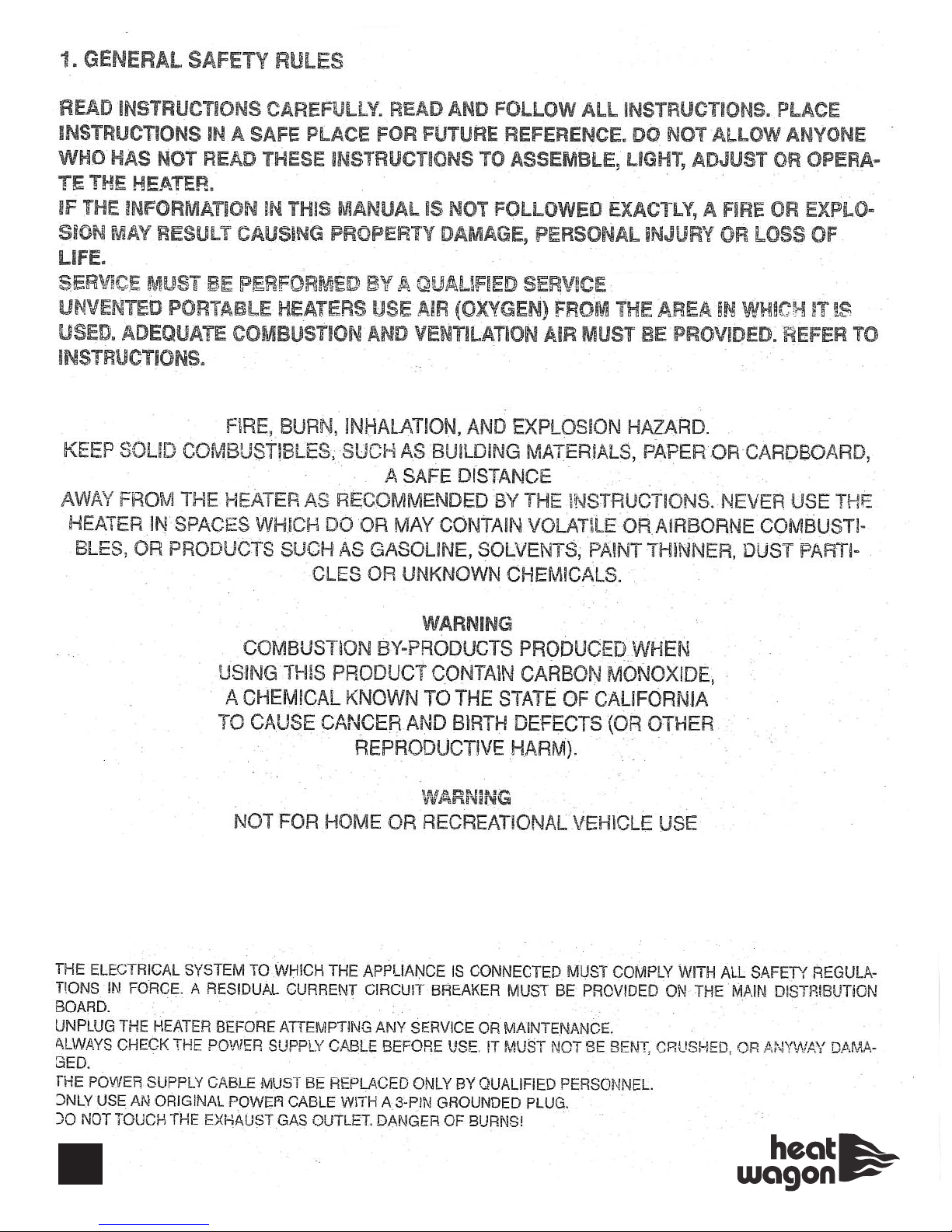
Fire, burn, inhalation, and explosion hazard. Keep solid combustibles, such as building materials, paper or cardboard, a safe distance away from the heater as recommended by the instructions. Never use the heater in spaces which do or may contain
volatile or airborne combustibles, or products such as gasoline, solvents, paint thinner, dust particles or unknown chemicals.
Not for home or recreational vehicle use!
Heater is not intended for use in pest remediation.
We cannot anticipate every use which may be made for our heaters. CHECK WITH YOUR
LOCAL FIRE SAFETY AUTHORITY IF YOU HAVE QUESTIONS ABOUT LOCAL REGULATIONS.
Other standards govern the use of fuel gases and heat producing products in specific applications. Your local authority can advise you about these.
FOR YOUR SAFETY
DO NOT USE THIS HEATER IN A SPACE WHERE GASOLINE OR OTHER LIQUIDS HAVING FLAMMABLE VAPORS ARE STORED OR USED.

Installation and Maintenance Manual
Model HVF180-HVF300
Construction Heater
Table of Contents:
Page
Safety and Caution . . . . . . . . . . . . . . . . . . . . . . . . . . . . . . . . . . . . . . . . . . .3
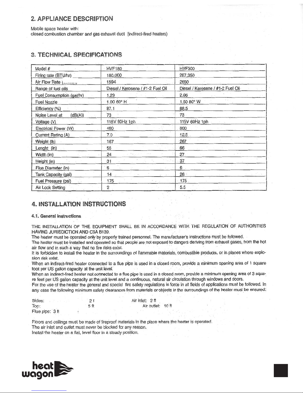
Specifications . . . . . . . . . . . . . . . . . . . . . . . . . . . . . . . . . . . . . . . . . . . . . . .4
Installation . . . . . . . . . . . . . . . . . . . . . . . . . . . . . . . . . . . . . . . . . . . . . . . . .4
Operating Instructions . . . . . . . . . . . . . . . . . . . . . . . . . . . . . . . . . . . . . . . .7
Maintenance . . . . . . . . . . . . . . . . . . . . . . . . . . . . . . . . . . . . . . . . . . . . . . . .8
Troubleshooting . . . . . . . . . . . . . . . . . . . . . . . . . . . . . . . . . . . . . . . . . . . . .8
Wiring Diagrams . . . . . . . . . . . . . . . . . . . . . . . . . . . . . . . . . . . . . . . . . . . .9
Illustrated Parts Breakdown . . . . . . . . . . . . . . . . . . . . . . . . . . . . . . . .10-11
Advance Troubleshooting . . . . . . . . . . . . . . . . . . . . . . . . . . . . . . . . .12-17
Chimney/Exhaust Set-up . . . . . . . . . . . . . . . . . . . . . . . . . . . . . . . . . . . . .18
Accessories . . . . . . . . . . . . . . . . . . . . . . . . . . . . . . . . . . . . . . . . . . . . . . . .19
WARRANTY
All new Heat Wagon and Sure Flame heaters and fans are guaranteed against defective materials and workmanship for one (1) year from invoice date.
Warranty repairs may be made only by an authorized, trained and certified Heat Wagon dealer. Warranty
repairs by other entities will not be considered. Warranty claims must include model number and serial
number.
LIMITATIONS
Warrant claims for service parts (wear parts) such as spark plugs, igniters, flame rods will not be allowed.
Diagnostic parts such as voltage meters and pressure gauges are not warrantable.
Evidence of improper fuel usage, fuel pressures outside of manufacturer’s specification, poor fuel quality,
and improper electric power, misapplication or evidence of abuse may be cause for rejection of warranty
claims.
Travel time, mileage and shipping charges will not be allowed. Minor adjustments of heaters are dealers’
responsibility. Defective parts must be tagged and held for possible return to the factory for 60 days from
date of repair. The factory will provide a return goods authorization, (RGA) for defective parts to be
returned.
No warranty will be allowed for parts not purchased from Heat Wagon.
342 N. Co. Rd. 400 East • Valparaiso, IN 46383
219-464-8818 • 888-432-8924 • Fax 800-255-7985
www.heatwagon.com
TECHNICIAN.
4
(CFM)
6 ft.
5
Indirect Oil Theory of Operation
When the on/off power switch is turned on, power is sent to a power indicator light on the control panel. Power is also
received by the control board. The control board sends power out to a thermostat “socket”. The socket must have a
“jumper cap” or a remote thermostat plugged into the socket. The heater has a heating element in the fuel filter, the element will now receive power from the control board, and begin pre-heating the fuel.
When the thermostat jumper cap is in place, or the remote thermostat is turned up to call for heat, the control board will
begin the start up sequence. During the first step of start up called the purge cycle, the control board powers the motor
and transformer for a short period of approximately ten seconds. The turning motor provides airflow and the transformer
provides spark to light and burn off any residual fuel remaining from prior operation. At this time the fuel solenoid valve
receives no power and remains closed. All fuel pumped is sent back to the fuel tank thru the fuel pump’s return line.
During this purge cycle the photocell which is connected to the control board looks for the presence of flame in the combustion chamber. If flame is detected during the purge cycle, the control board “locks out” or removes power from all
components. The heater is equipped with an air proving switch, air from the turning fan blade must close the switch,
otherwise lock out will occur.
Once the purge cycle is completed successfully, the ignition cycle can begin. The control board now sends power to the
fuel solenoid valve. The valve opens allowing fuel to flow thru to the nozzle. The photocell must now detect flame within
several seconds or the control board will lock out. If flame is detected briefly and then lost, the purge and ignition cycles
are repeated once more and if ignition is not achieved, lock out occurs. Control board removes power to the transformer
a short time after ignition is achieved. If for any reason ignition is lost, the control board will remove power to the fuel
solenoid valve and the purge and ignition cycles will begin. Once ignition is established the thermostat will cycle the
heater on and off as needed.
If lock out occurs the reset button will trip. The heaters need a thirty second wait before the reset will function again.
6
 Loading...