

Page 1
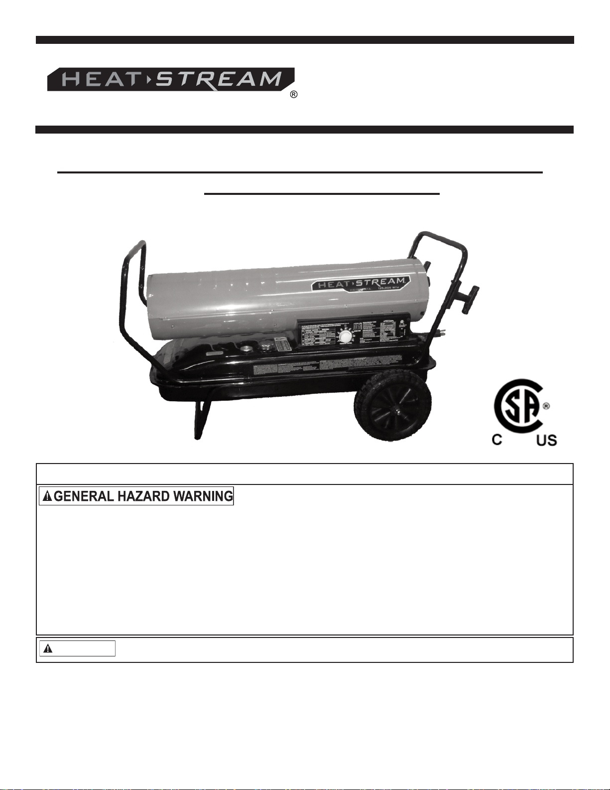
User ’s Manual and
Operating Instructions
Model Numbers: HS-45-KFA, HS-70T-KFA, HS-125T-KFA,
HS-175T-KFA, HS-215T-KFA
Consumer: Please Read These Instructions And Keep For Your Reference
FAILURE TO COMPLY WITH THE PRECAUTIONS AND INSTRUCTIONS PROVIDED WITH THIS
HEATER, CAN RESULT IN DEATH, SERIOUS BODILY INJURY AND PROPERTY LOSS OR
DAMAGE FROM HAZARDS OF FIRE, EXPLOSION, BURN. ASPHYXIATION, CARBON
MONOXIDE POISONING AND / OR ELECTRIC SHOCK.
ONLY PERSONS WHO CAN UNDERSTAND AND FOLLOW THE INSTRUCTIONS SHOULD USE
OR SERVICE THIS HEATER.
IF YOU NEED ASSISTANCE OR HEATER INFORMATION SUCH AS AN INSTRUCTIONS
MANUAL, LABEL, ETC. CONTACT THE MANUFACTURER.
WARNING
This is an unvented portable heater. It uses air (oxygen) from the area in which it is used. Adequate combustion
and ventilation air must be provided. Refer to VENTILATION on Page 7.
© Pinnacle Products International, Inc.
668 Stony Hill Road #302 Yardley, PA 19067 USA Toll Free: (800) 641-6996
Fax: (215) 891-8461 Web: www.heatstream.us Email: info@pinnacleint.com
701000273-12
Page 2
Table of Contents
DANGER
DANGER
NEVER LEAVE HEATER
UNATTENDED WHILE BURNING OR WHILE CONNECTED
TO A POWER SOURCE
Safety Information........................................... 2-3
Unpacking ...........................................................3
Features ......................................................... 3-4
Assembly ........................................................ 5-6
Operation .........................................................7-9
Fuels .................................................................. 7
Theory of Operation ........................................... 7
Ventilation .......................................................... 7
Safety Information
WARNING
KEEP SOLID COMBUSTIBLES, SUCH AS
BUILDING MATERIALS, PAPER OR CARDBOARD, A SAFE DISTANCE AWAY FROM THE
HEATER AS RECOMMENDED BY THESE
INSTRUCTIONS. NEVER USE THE HEATER
IN SPACES WHICH DO OR MAY CONTAIN
VOLATILE OR AIRBORNE COMBUSTIBLES,
OR PRODUCTS SUCH AS GASOLINE,
SOLVENTS, PAINT THINNERS, DUST
PARTICLES OR UNKNOWN CHEMICALS.
WARNING
WARNING
these safety and operating instructions.
California Residents: Combustion by-products
produced when using this product contain carbon monoxide, a
chemical known to the state of California to cause cancer and
birth defects (or other reproductive harm).
Massachusetts Residents: Massachusetts state law
prohibits the use of this heater in any building which is used in
whole or in part for human habitation. Use of this heating device
in Massachusetts requires local fire department permit (M.G.L.C.
148, Section 10A).
New York City Residents: The New York City Fire
Code prohibits the storage, handling and use of kerosene fueled
heaters for space heating. Any person violating that provision
may be punished by a fine up to $10,000 and a term of
imprisonment up to 6 months.
WARNING
the filter and seals. Any damage caused by using BioDiesel will not be covered by warranty.
result in death or serious injury.
FIRE, BURN, INHALATION,
AND EXPLOSION HAZARD.
NOT FOR HOME OR
RECREATIONAL USE.
Do not operate this heater until you
have read, and thoroughly understand
This heater is NOT suitable for use with
Bio-Diesel; use of Bio-Diesel will damage
Indicates an im minen tly hazardous
situation which, if not avoided, WILL
Long Term Storage ......................................... 8-9
Maintenance ................................................. 9-11
Exploded View ................................................. 12
Replacement Parts .......................................... 13
Wiring Diagram ................................................ 14
Troubleshooting ............................................... 15
Warranty ............................................ Back Cover
WARNING
COULD result in death or serious injury.
CAUTION
result in minor or moderate injury.
This is a kerosene, direct-fired, forced air heater. It is primarily
intended for use for temporary heating of buildings under
construction, alteration or repair. Direct-fired means that all of the
combustion products of the heater enter the heated space. This
appliance is rated at 98% combustion efficiency, but does produce
small amounts of carbon monoxide. Carbon monoxide is toxic.
Humans can tolerate small amounts of carbon monoxide, and
precautions should be taken to provide proper ventilation. Failure
to provide proper ventilation according to this manual can result in
death. Early signs of carbon monoxide poisoning resemble the flu.
Symptoms of improper ventilation are:
headache * dizziness * burning of the nose and eyes
*
For optimal performance of this heater, it is strongly suggested
that 1-K kero sene be used. 1-K kerosene has been refined to
virtually eliminate contami nants, such as sulfur, which can cause a
rotten egg odor during the operation of the heater. However, #1 or
#2 fuel oil (diesel fuel) may also be used if 1-K kero sene is not
available. Be advised that these fuels do not burn as clean as 1-K
kerosene, and care should be taken to provide more fresh air
ventilation to accommodate any added contaminants that may be
added to the heated space. Use of #1 or #2 fuel oil may result in
more periodic maintenance.
*
WARNING
- Use this heater only in well ventilated areas! Provide at least a
three square foot (2,800 sq cm) opening of outside air for every
100,000 BTU/hr of heater rating.
- People with breathing problems should consult a physician
before using the heater.
- Carbon Monoxide Poisoning: Early signs of carbon monoxide
poisoning resemble flu-like symptoms such as headaches,
dizziness, and/or nausea. If you have these symptoms, your
heater may not be working properly.
Indicates a poten tially hazardous
situation which, if not avoided,
Indicates a poten tially hazardous
situa tion which, if not avoided, MAY
Carbon Monoxide poisoning may lead to
death!
nausea * dry mouth * sore throat
Risk of indoor air pollution!
© 2012, Pinnacle Products International, Inc.
2
Kerosene User’s Manual
Page 3
Safety Information (continued)
NEVER LEAVE HEATER
UNATTENDED WHILE BURNING OR WHILE CONNECTED
TO A POWER SOURCE
Simply locate fan in safe, desired position on level ground,
and connect to approved power source.
-
Get fresh air at once! Have the heater serviced. Some people
are more affected by carbon monoxide than others. These
include pregnant women, those with heart or lung problems,
anemia, or those under the influence of alcohol, or at high
altitudes.
WARNING
Risk of burns / fire / explosion!
- NEVER use fuels such as gasoline, benzene, paint thinners, or
other oil compounds in this heater (RISK OF FIRE OR
EXPLOSION).
- NEVER refill the heater’s fuel tank while heater is operating or
still hot. This heater is EXTREMELY HOT while in operation.
- Keep all combustible materials away from this heater.
- NEVER block air inlet (rear) or air outlet (front) of heater.
- NEVER use duct work in front or at rear of heater.
- NEVER move or handle heater while still hot.
- NEVER transport heater with fuel in its tank.
- If equipped with a thermostat, the heater may start at any time.
- ALWAYS locate heater on a stable and level surface.
Unpacking
- ALWAYS keep children and animals away from heater.
- Bulk fuel storage should be a minimum of 25 ft. from heaters,
torches, portable generators, or other sources of ignition. All
fuel storage should be in accordance with federal, state, or
local authorities having jurisdiction.
- Never use this heater in living or sleeping areas.
- NEVER use this heater where flam mable vapors may be
present.
WARNING
- Use only the electrical power (voltage and frequency) specified
on the model plate of the heater. Use only a three- prong,
grounded outlet and extension cord.
Risk of electric shock!
- ALWAYS install the heater so that it is not directly exposed to
water spray, rain, dripping water, or wind.
- ALWAYS unplug the heater when not in use.
Minimum clearance from Combustibles:
45k 70k 125k 175k 215k
Top 4 ft. 4 ft. 4 ft. 4 ft. 4 ft.
Sides 4 ft. 4 ft. 4 ft. 4 ft. 4 ft.
Front 8 ft. 8 ft. 8 ft. 8 ft. 10 ft.
Remove the heater and all of the packaging materials from the
shipping carton.
NOTE: Save the box and packaging materials for future storage.
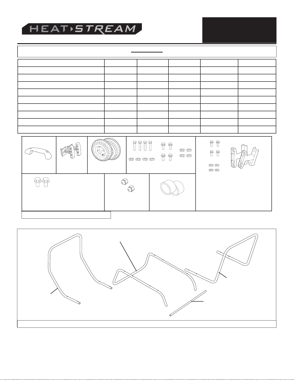
Check the chart below to be sure that you have all of the parts
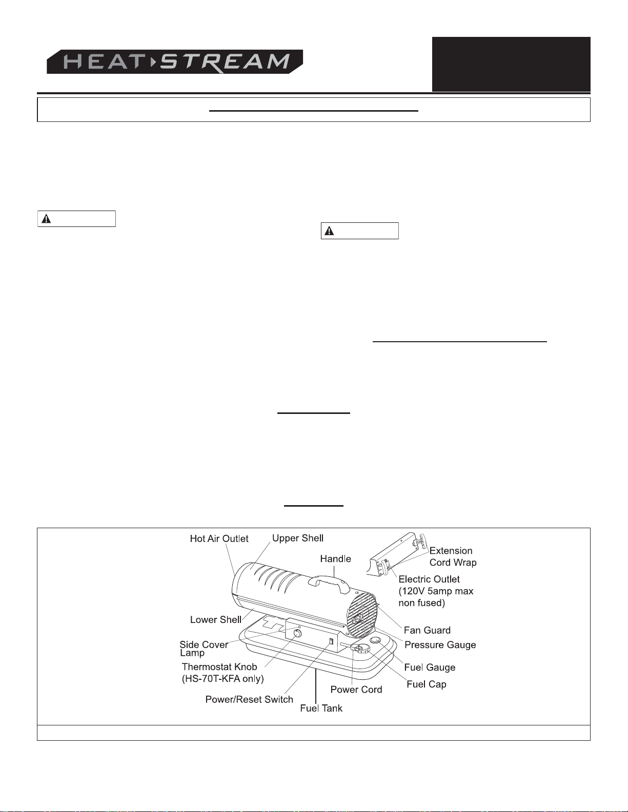
Features
required to assembly your heater. If you find that any parts are
missing, call 215-891-8460 for assistance in receiving the
missing components.
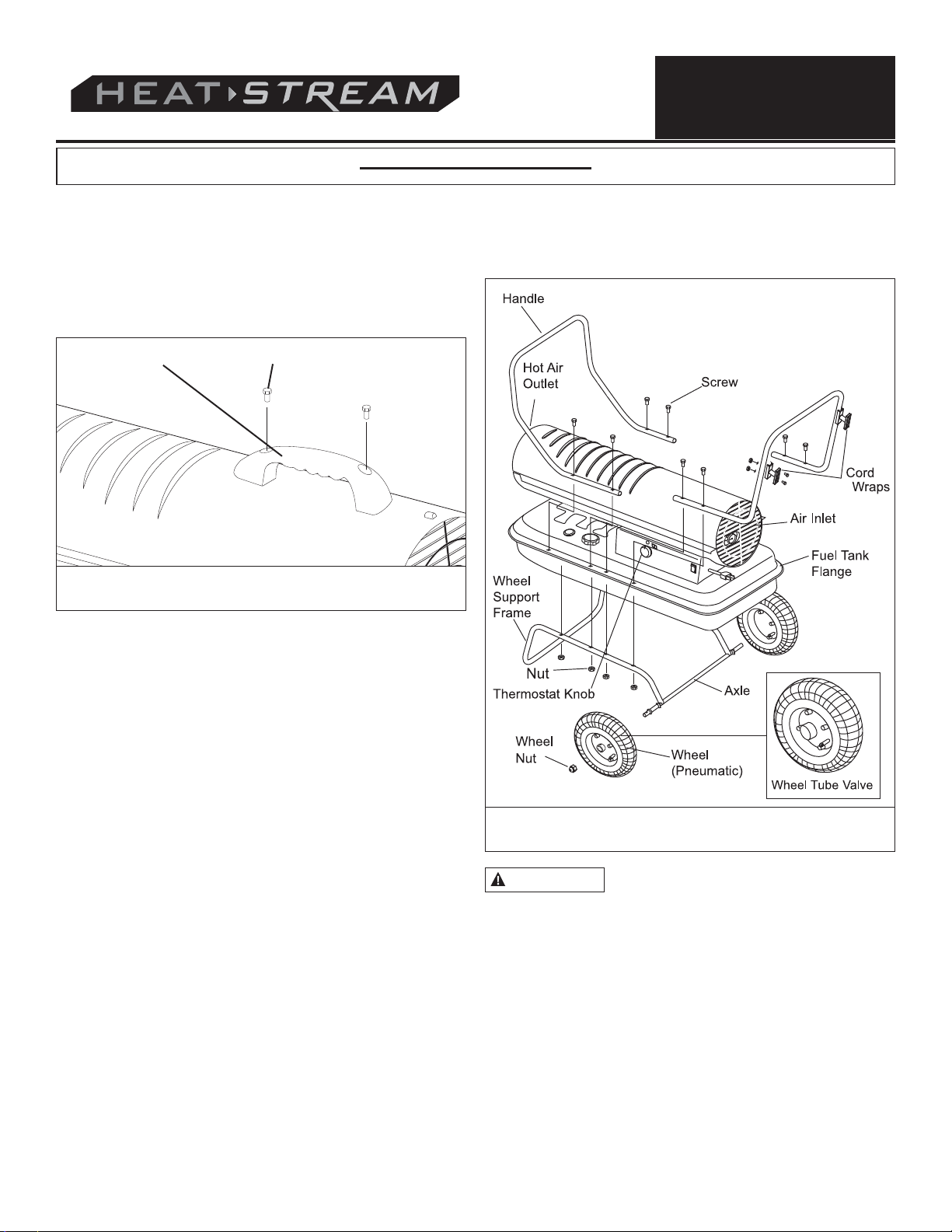
Figure 1: Features of Models HS-45/70T-KFA
© 2012, Pinnacle Products International, Inc.
3
Kerosene User’s Manual
Page 4
Features (Continued)
NEVER LEAVE HEATER
UNATTENDED WHILE BURNING OR WHILE CONNECTED
TO A POWER SOURCE
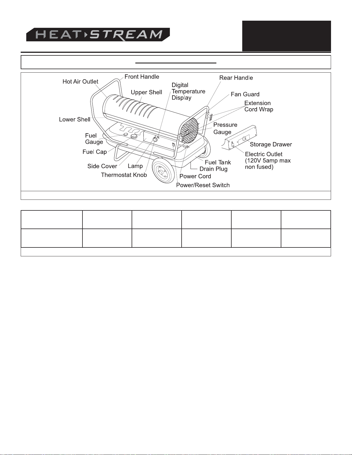
Figure 2: Features of Models HS-125T/175T/215T-KFA
HS-45-KFA HS-70T-KFA HS-125T-KFA HS-175T-KFA HS-215T-KFA
Fuel Consumption
Rate (Gallons)
.35 .53 .95 1.34 1.63
Figure 3: Product Specifications
© 2012, Pinnacle Products International, Inc.
4
Kerosene User’s Manual
Page 5
NEVER LEAVE HEATER
UNATTENDED WHILE BURNING OR WHILE CONNECTED
TO A POWER SOURCE
Assembly
HS-45-KFA HS-70T-KFA HS-125T-KFA HS-175T-KFA HS-215T-KFA
Wheel support frame NO NO YES YES YES
Wheel (2 pieces) NO NO YES YES YES
Front and Rear Handle NO NO YES YES YES
Axle NO NO YES YES YES
Top Handle YES YES NO NO NO
Screws & Nuts (A) 8 each NO NO YES YES YES
Screws & Nuts (B) 4 each YES YES NO NO NO
Wheel Nuts and Bushings NO NO YES YES YES
Cord Wrap YES YES YES YES YES
Handle
Hardware Kit Part#
70-056-0100
(HS-45 / 70T-KFA)
Cord Wraps Wheels
Screws and
Nuts(4 ea.)
Figure 4: Hardware Components
Wheel Support Frame
Front Handle
Frame Component Hardware
Wheel Nuts
Bushings
Screws and Nuts (4 ea.) and Cord
Wraps
Hardware Kit Part#:
70-056-0210
(HS-125T/ 175T / 215T-KFA)
Rear Handle
Axle
Figure 5: Frame Components for models HS-125T / 175T / 215T-KFA
© 2012, Pinnacle Products International, Inc.
5
Kerosene User’s Manual
Page 6
Assembly (Continued)
CAUTION
NEVER LEAVE HEATER
UNATTENDED WHILE BURNING OR WHILE CONNECTED
TO A POWER SOURCE
MODELS HS-45/70T-KFA ONLY
- Tools required: Medium phillips screw driver.
ASSEMBLING HANDLE
1.Align the holes in the upper housing with the 2 holes in the
handle as shown in Figure 6.
2. Insert and tighten screws securely with screw driver.
Handle
Screw
Figure 6: Attaching Handle for models HS-45 /
70T-KFA
ASSEMBLING CORDWRAP
1. Insert tabs on cordwrap into slots in shell support, lining up the
holes on the cordwrap with those on the side cover.
2. Insert and tighten screws securely with screw driver.
ASSEMBLING CORDWRAP
1. Align holes in cordwrap with corresponding holes in rear
handle. Insert screws (B) through holes, attach nuts and
tighten (see Figure 7.).
MODELS HS-125T/175T/215T-KFA ONLY
- Tools required: Medium phillips screw driver, 5/16” open end
or adjustable wrench, needle nose pliers.
ASSEMBLING FRAME AND WHEELS
1. Slide axle through holes in wheel support frame. Slide wheel
bushings and flat washer (A) on to each end of axle.
2. Slide wheels on to each axle, being sure that the valve stem (if
pneumatic) is to the outside (see Figure 7.).
3. Attach wheel nut to threaded axle and tighten.
4. Place heater on the assembled frame, making sure that the air
inlet end is by the wheels, and the mounting holes on the tank
flange of the heater align with holes in frame.
5. Take the front handle and align the mounting holes with the
corresponding holes in the tank flange/wheel frame. Slide a
screw (A) through the holes and loosely attach a nut. Repeat
for the other 3 holes, then fully tighten all 4 screws and nuts.
6. Repeat this process with the rear handle
NOTE: The front handle is longer than the rear handle.
© 2012, Pinnacle Products International, Inc.
.
Figure 7 Attaching Handle for models HS-125T /
175T / 215T-KFA
Do not operate heater without support
frame fully assembled to tank.
6
Kerosene User’s Manual
Page 7
Operation
CAUTION
KEROSENE (1-K)
For optimal performance of this heater, it is strongly suggested
that 1-K kero sene be used. 1-K kerosene has been refined to
virtually eliminate contami nants, such as sulfur, which can cause a
rotten egg odor during the operation of the heater. However, #1 or
#2 fuel oil (diesel fuel) may also be used if 1-K kerosene is not
available. Be advised that these fuels do not burn as clean as 1-K
kerosene, and care should be taken to provide more fresh air
ventilation to accommodate any added contaminants that may be
added to the heated space. Using diesel fuel can cause excess
soot production. DO NOT use any fuel that is not approved
above.
NOTE: Kerosene should only be stored in a blue container that is
clearly mark ed “kerosene”. Never store kero sene in a red
container. Red is associ ated with gasoline.
- NEVER store kerosene in the living space. Kerosene should be
stored in a well ventilated area outside the living area.
- NEVER use fuel such as gasoline, benzene, alcohol, white gas,
camp stove fuel, paint thinners, or other oil compounds in this
heater (THESE ARE VOLATILE FUELS THAT CAN CAUSE A
FIRE OR EXPLOSION).
- NEVER store kerosene in direct sunlight or near a source of
heat.
- NEVER use kerosene that has been stored from one season to
the next. Kerosene deteriorates over time. OLD KEROSENE
WILL NOT BURN PROPERLY IN THIS HEATER.
- Use 1-K kerosene in this heater. #1 fuel is a suitable substitute.
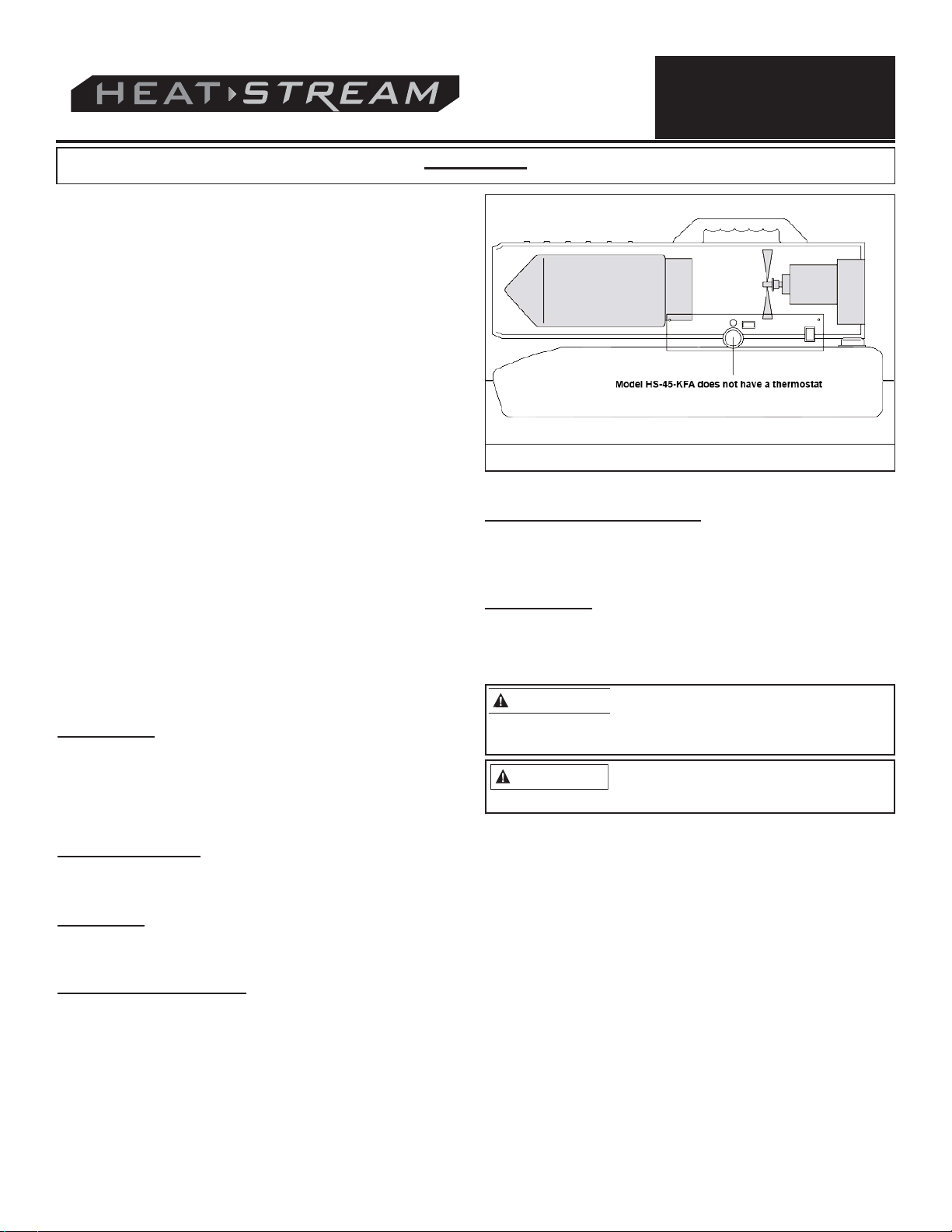
THEORY OF OPERATION
Fuel System: This heater is equipped with an air pump that
operates off of the electric motor. The pump forces air through
the air line connected to the fuel tank, drawing fuel to the nozzle
in the burner head. Air also passes through the nozzle where it
mixes with the fuel and is sprayed into the combustion chamber
in a fine mist.
Quick-Fire Ignition: A transformer sends high voltage to a two
pronged spark plug. The spark ignites the fuel/air mixture as it is
sprayed into the combustion chamber.
NEVER LEAVE HEATER
UNATTENDED WHILE BURNING OR WHILE CONNECTED
TO A POWER SOURCE
Figure 8 Theory of Operation
Electrical System Protection: The heaters’ electrical system
is protected by a circuit breaker that protects the system
components from damage. If the heater fails, check the fuse first,
and replace if necessary.
Flame Sensor: The heater uses a photocell to “see” the flame
in the combustion chamber. Should the flame extinguish, the
sensor will stop electrical current and the heater will shut off.
FUELING THE HEATER
NEVER FILL THE FUEL TANK INDOORS.
ALWAYS FILL THE TANK OUTDOORS.
BE SURE THAT THE HEATER IS ON LEVEL GROUND WHEN
FUELING, AND NEVER OVERFILL THE FUEL TANK.
WARNING
EXPLOSION COULD RESULT.
It is always a good idea to fire the heater outdoors for the first
time. This will allow any oils used in the manufacturing process to
be burned off in a safe environment. This initial burn should last
at least 10 minutes
NEVER REFUEL THIS HEATER WHILE IT
IS HOT OR OPERATING. FIRE OR
Air System: A fan is turned by the heavy duty motor, which
forces air around and into the combustion chamber, where it is
super-heated and forced out the front of the chamber.
Temperature Limit Control: This heater is equipped with a
Temperature Limit Control designed to turn the heater off should the
internal temperature rise to an unsafe level. If this device activates
and turns your heater off, it may require service.
Once the temperature falls below the reset temperature, you will
be able to start your heater.
© 2012, Pinnacle Products International, Inc.
VENTILATION
Risk of indoor air pollution. Use heater only in well
ventilated areas.
Always provide a fresh air opening in the heated space of at
least three square feet (2,800 sq. cm) for each 100,000 BTU/Hr.
of heater output. Provide a larger opening if more heaters are
being used. As an example, an HS-215T-KFA heater will require:
- a two-car garage door open 6 inches, or
- a single car garage open 9 inches, or
- two thirty two inch wide windows open fifteen inches.
7
Kerosene User’s Manual
Page 8
Operation (Continued)
NEVER LEAVE HEATER
UNATTENDED WHILE BURNING OR WHILE CONNECTED
TO A POWER SOURCE
TO START THE HEATER
1. Fill the tank with kerosene until fuel gauge points to “F”.
2. Be sure fuel cap is secure.
3. Plug power cord into three prong, grounded extension cord
and plug extension cord into three prong 120V grounded outlet. The extension cord should be at least six feet long.
- Extension cord wire size requirements are as follows:
› 6 to 10 feet (1.8 to 3 meters), use 18 AWG wire.
› 11 to 100 feet (3.4 to 30.4 meters), use 16 AWG wire.
› 101 to 200 feet (30.8 to 61 meters), use 14 AWG wire.
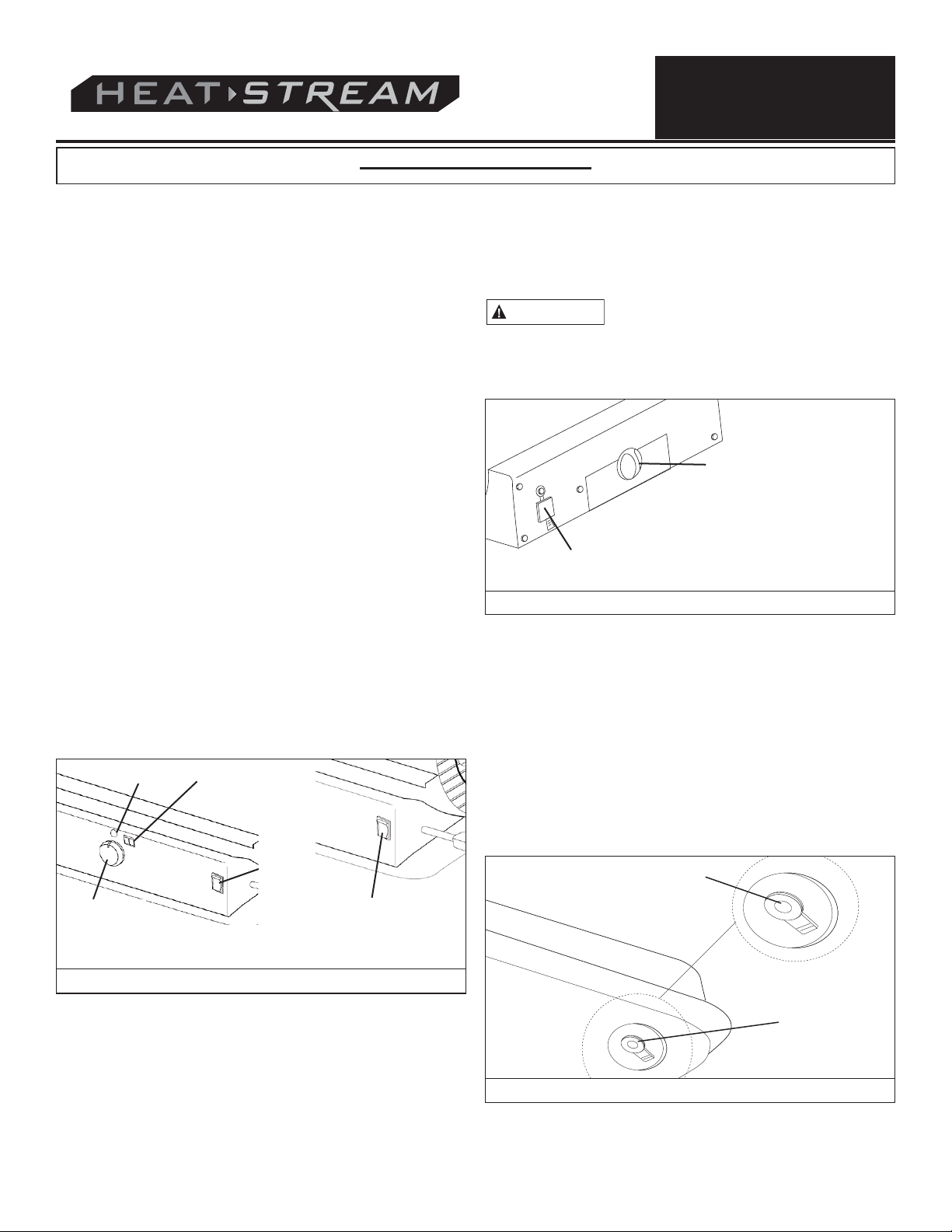
4. Turn thermostat control knob to desired temperature setting
(70/125/175/215 only). The setting range is from 40°F to 110
F. Push the Power switch to the “ON” position (See figure 9).
The power indicator lamp and room temperature display
(125/175/215 only) will light and the heater will start.
NOTE: The room temperature display (125/175/215 only) will
indicate the following:
- When temperature is less than 0°F, display says “LO”.
- When temperature is above 99°F, display says “HI”.
- Between 0°and 99°F display shows actual temperature.
5. If the heater does not fire, the thermostat may be set too low.
Turn the Control Knob to a higher setting until heater fires. If
the heater still does not start, push Power Switch to “OFF”,
then back to “ON”. If heater still does not fire, see
Troubleshooting Guide on Page 15.
NOTE: The electrical components of this heater are protected by
a fuse mounted in the PC board. If the heater fails to fire, check
this fuse first, and replace if necessary. Also check the power
source to be sure that the proper voltage is being provided to the
heater.
Lamp
Room Temp.
Display(Except
HS-70T-KFA)
TO RESTART THE HEATER
1. Wait ten seconds after shutting off heater.
2. Turn the Power Switch to “ON” position.
3. Be sure to follow all starting procedure precautions.
ELECTRICAL OUTLET
WARNING
- Never plug in an appliance with more than a 5 amp rating into
this outlet.
- Always keep outlet covered when not in use.
°
Shock Hazard!
Storage Drawer (except
HS-45 / 70T-KFA)
Electric Outlet (120v 5amp max
non fused)
Figure 10: Electric Outlet Detail
LONG TERM STORAGE
Drain Fuel Tank
For models HS-45/70T-KFA, drain fuel through the fuel cap opening using an approved siphon. For models HS-125/175/215-KFA,
drain fuel through the Drain Plug at the bottom of the Fuel Tank.
2. To remove the Drain Plug (125/175/215), pull the Plug Grip
downward and remove seal head from drain hole in tank (See
Figure 11).
Power
Switch
Thermostat
Control Knob
Models HS-70T / 125T / 175T / 215T-KFA
Power Switch
Model HS-45-KFA
Figure 9: Control Panel for all models
TO STOP THE HEATER
Simply turn the Power switch to “OFF” position and unplug the
Power Cord.
© 2012, Pinnacle Products International, Inc.
Plug Grip
Figure 11: Drain Plug Removal
8
Kerosene User’s Manual
Drain Plug
Page 9
Operation (Continued)
NEVER LEAVE HEATER
UNATTENDED WHILE BURNING OR WHILE CONNECTED
TO A POWER SOURCE
3. Using a small amount of kerosene, rinse and swirl the
kerosene inside of the Fuel Tank. Empty the tank fully.
4. To replace, push the drain head fully into the drain hole and
secure by pushing the seal cap fully into the head hole (See
Figure 12).
IMPORTANT: Never store leftover kerosene over the summer.
Using old fuel can damage your heater.
Drain Plug
Fuel Tank
Seal Head
Head Flange
Head
Flange
Cap Flange
Seal Cap
Figure 12: Drain Plug Reinstall
Maintenance
WARNING
Use only original equipment replacement parts. The use of
alternate or third party components can cause unsafe operating
conditions, and will void your warranty.
We suggest following a maintenance schedule as follows:
FUEL/FUEL TANK:
Flush every 200 hours of operation or as needed. Do not use
water to flush the tank. Use fresh 1-K kerosene only.
AIR FILTERS:
The Air Intake Filter should be replaced or washed with soap and
water and dried thoroughly every 500 hours of operation, or less,
depending on conditions.
The Output and Lint Filters should be replaced every 500 hours
of operation or less, depending on conditions.
NOTE: Use of diesel may require additional maintenance..
FAN BLADES:
Blades should be cleaned at least once per heating season,
depending on conditions.
Remove all accumulated dust and dirt with a damp cloth, taking
care not to bend any of the fan blades. Be sure fan blades are
dry before re-starting the heater. For Fan removal, see Figure
14.
Never service heater while it is plugged in
or while hot!
Lint Filter
End Filter Cover
Figure 13: Filter Replacement
Set Screw
Motor Shaft
Fan Blade
Figure 14: Fan Replacement
Air Output Filter
Intake Filter
Flush
© 2012, Pinnacle Products International, Inc.
9
Kerosene User’s Manual
Page 10
Maintenance (Continued)
NEVER LEAVE HEATER
UNATTENDED WHILE BURNING OR WHILE CONNECTED
TO A POWER SOURCE
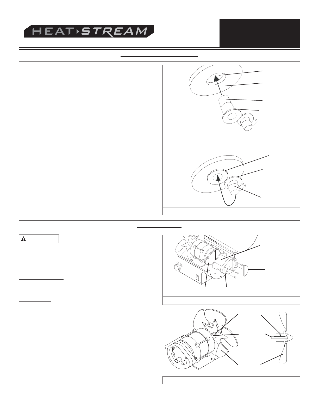
NOZZLES:
Nozzles should be cleaned or replaced at least once per heating
season. Contaminated fuel could make this necessary
immediately
To clean dirt from nozzle, blow compressed air through nozzle
front. It may be necessary to soak nozzle in clean 1-K kerosene
to help loosen any particles.
NOTE: Use of diesel may require additional maintenance. Using
this heater without proper maintenance or with contaminated or
old fuel may lead to improper combustion and possible soot
production. BE SURE FUEL USED IS APPROVED (see
OPERATION on page 6).
.
Burner Head
Screw
Spark Plug
Ignitor Wire
Fuel Line Hose
Air Line Hose
SPARK PLUG:
Clean and re-gap every 600 hours of operation, or replace as
needed.After removing the Spark Plug, clean the terminals with a
wire brush. Re-gap the terminals to 0.140” (3.5mm).
Ignitor Wire
Spark Plug
Burner Head
Gap
Figure 16: Spark Plug Replacement
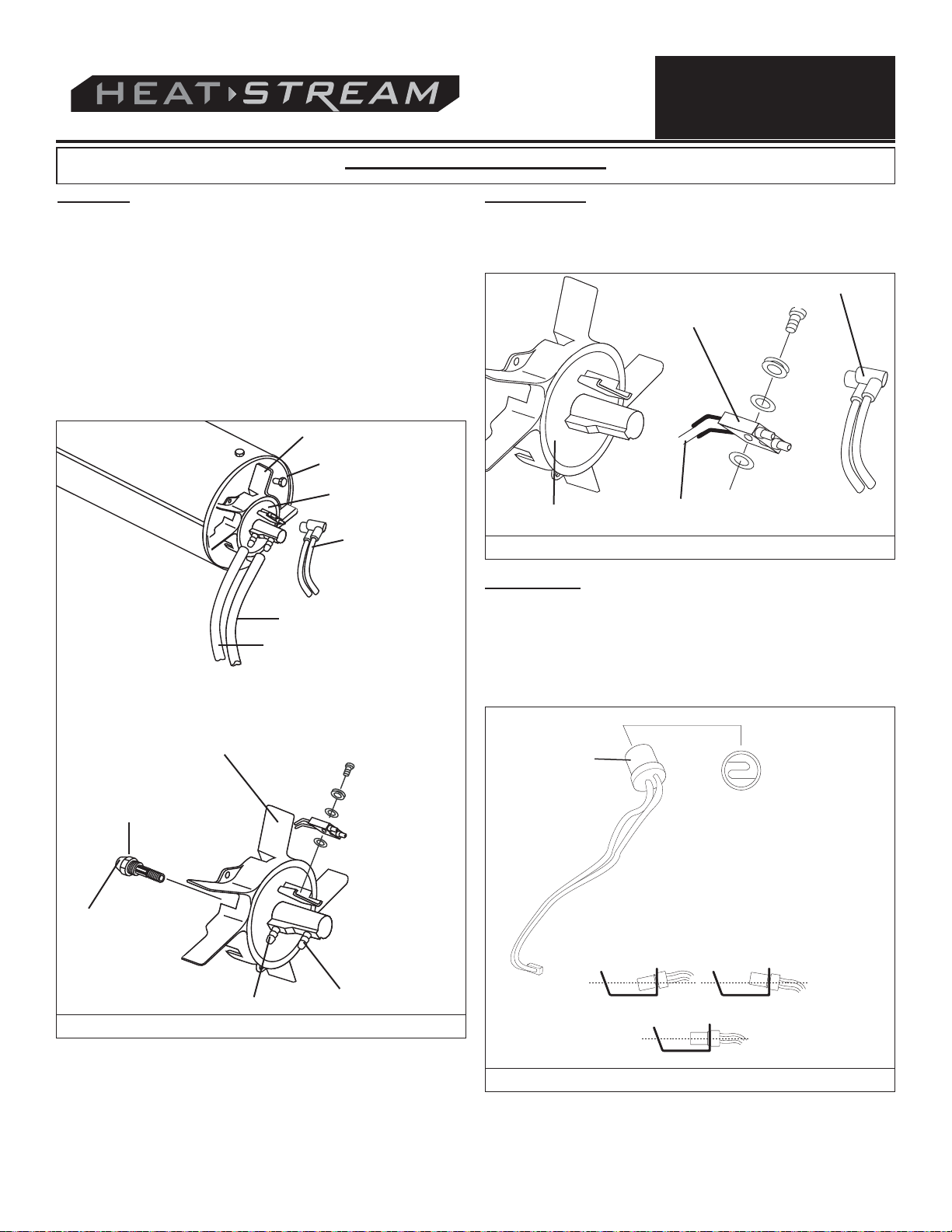
PHOTOCELL:
The Photocell should be cleaned at least once per heating
season or more depending on conditions.
Use a cotton swap dipped in water or alcohol to clean the lens of
the Photocell. Note the proper Photocell position as noted in
Figure 17 and Figure 18.
Burner Head
Nozzle
Nozzle Face
Air Line Fitting
Fuel Line Fitting
Figure 15: Nozzle Replacement
© 2012, Pinnacle Products International, Inc.
Photocell
Installing Photocell:
1) Incorrect
2) Correct
Figure 17: Photocell Positioning
10
Kerosene User’s Manual
Photocell
Lens
Page 11
Maintenance (Continued)
NEVER LEAVE HEATER
UNATTENDED WHILE BURNING OR WHILE CONNECTED
TO A POWER SOURCE
Photocell
Wire
Circuit Board
except
HS-45-KFA
Figure 18: Photocell Position in Heater
Use of diesel may require additional maintenance.
maintenance can lead to poor combustion and soot
production!
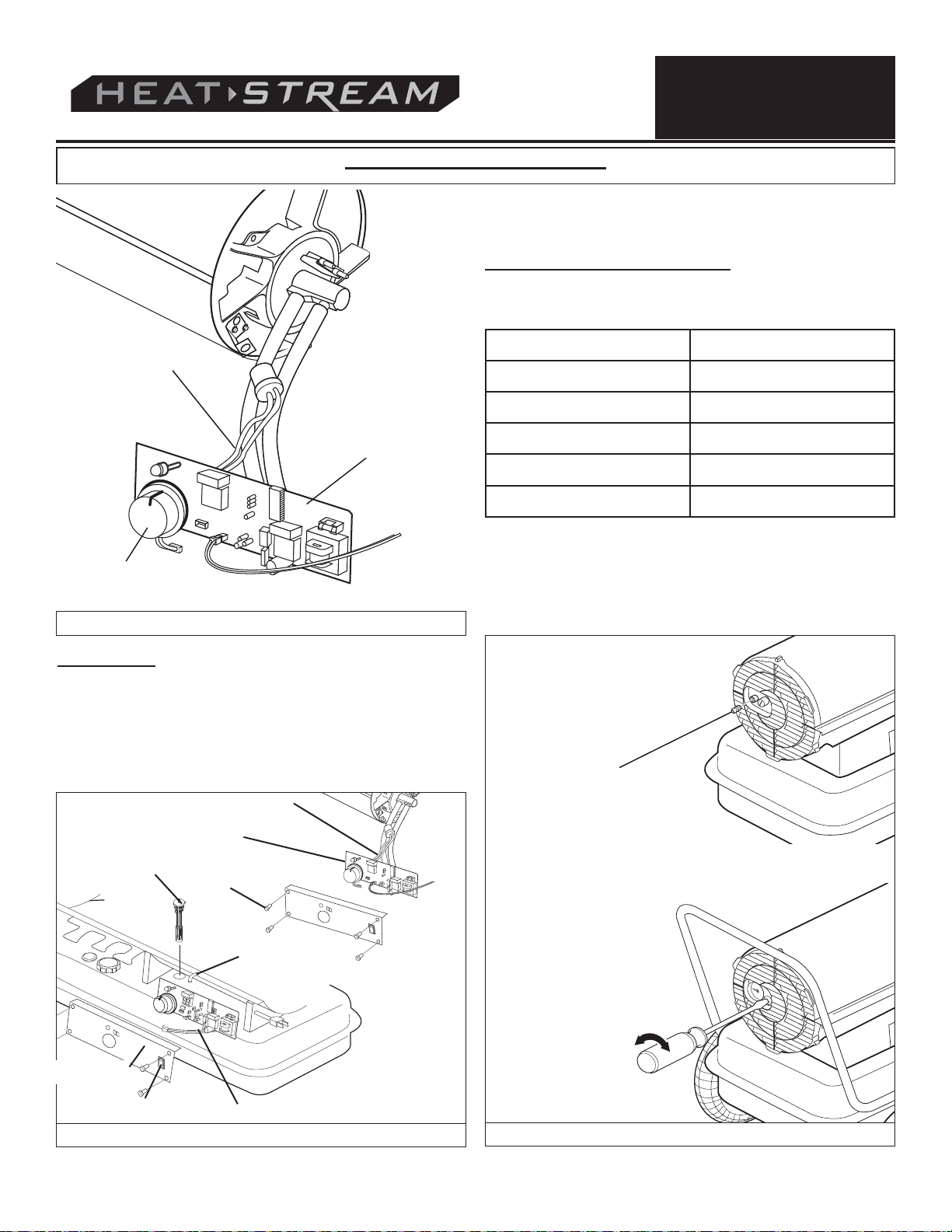
PUMP PRESSURE ADJUSTMENT:
While heater is operating, turn relief valve clockwise to increase,
counterclockwise to decrease (see Figure 20). Use flat blade
screwdriver to turn valve. Correct pump pressure is as follows:
Improper
Model # Pump Pressure
HS-45-KFA 3.0 PSI
HS-70T-KFA 4.0 PSI
HS-125T-KFA 5.0 PSI
HS-175T-KFA 7.5 PSI
HS-215T-KFA 9.0 PSI
Tolerance ± 10%
For best measurement of pressure, test with full tank of
fuel. Optimum pressure occurs when the nose cone is
cherry red and there are no extending flames from the
heater.
FUEL FILTER:
The Fuel Filter should be cleaned at least twice per heating
season by rinsing it in clean 1-K kerosene. Contaminated fuel
could make this necessary immediately (See Figure 19).
NOTE: To remove the filter from models HS-45 / 70T-KFA, turn
filter 90°clockwise. To remove the filter from models HS-125T /
175T / 215T-KFA, turn filter 90°counter-clockwise.
Photocell Wire
Circuit Board
Fuel Filter
Side Cover
Power Switch
Screw
Fuel Line
Power Switch Wire
Adjusting
Screw
Figure 19: Fuel Filter Replacement
© 2012, Pinnacle Products International, Inc.
Figure 20: Pump Pressure Adjustment
11
Kerosene User’s Manual
Page 12

Exploded View
NEVER LEAVE HEATER
UNATTENDED WHILE BURNING OR WHILE CONNECTED
TO A POWER SOURCE
Figure 21: Exploded View for Models HS-45 / 70T / 125T / 175T / 215T-KFA
© 2012, Pinnacle Products International, Inc.
12
Kerosene User’s Manual
Page 13

NEVER LEAVE HEATER
UNATTENDED WHILE BURNING OR WHILE CONNECTED
TO A POWER SOURCE
Parts List
Item Part Number for Models:
No. Description HS-45-KFA HS-70T-KFA HS-125T-KFA HS-175T-KFA HS-215T-KFA
1 Fuel Tank Assembly 70-002-0100 70-002-0100 70-002-0200 70-002-0300 70-002-0300
2 Drain Plug – – 70-002-0105 70-002-0105 70-002-0105
3 Fuel Gauge Assembly 70-007-0110 70-007-0115 70-007-0210 70-007-0210 70-007-0215
4 Fuel Filter Assembly 70-003-0100 70-003-0100 70-003-0200 70-003-0200 70-003-0200
5 Fuel Cap 70-006-0100 70-006-0100 70-006-0100 70-006-0100 70-006-0100
6 Power Cord 70-034-0100 70-034-0100 70-034-0200 70-034-0200 70-034-0200
7 Power Switch 70-038-0100 70-038-0100 70-038-0100 70-038-0100 70-038-0100
8 Window Display – – 70-040-0100 70-040-0100 70-040-0100
9 Thermostat Control Knob – 70-031-0100 70-031-0100 70-031-0100 70-031-0100
10 Lower Shell – – – – –
11 Air Line 70-035-0100 70-035-0200 70-035-0300 70-035-0400 70-035-0500
12 Thermostat Limit Control 70-019-0100 70-019-0100 70-019-0100 70-019-0100 70-019-0200
13 Combustion Chamber Assembly 70-011-0100 70-011-0200 70-011-0300 70-011-0400 70-011-0500
14 Photocell Bracket 70-010-0101 70-010-0101 70-010-0101 70-010-0101 70-010-0101
15 Fuel Line 70-036-0100 70-036-0200 70-036-0300 70-036-0400 70-036-0500
16 Photocell Assembly 70-016-0100 70-016-0100 70-016-0100 70-016-0100 70-016-0100
17 Burner Head Assembly 70-014-0100 70-014-0200 70-014-0300 70-014-0400 70-014-0500
18 Nozzle Kit 70-015-0100 70-015-0200 70-015-0300 70-015-0400 70-015-0500
19 Nozzle Seal Washer – – – – –
20 Nozzle Seal Spring – – – – –
21 Nozzle Sleeve – – – – –
22 Burner Head – – – – –
23 Spark Plug Kit 70-052-0100 70-052-0100 70-052-0200 70-052-0200 70-052-0200
24 Motor and Pump Assembly 70-020-0550 70-020-0550 70-020-0555 70-020-0560 70-020-0565
25 Motor 70-021-0500 70-021-0500 70-021-0510 70-021-0520 70-021-0520
26 Pump Body 70-020-0101 70-020-0101 70-020-0101 70-020-0101 70-020-0401
27 Rotor Kit 70-022-0100 70-022-0100 70-022-0100 70-022-0100 70-022-0200
28 Blade – – – – –
29 End Pump Cover 70-020-0102 70-020-0102 70-020-0102 70-020-0102 70-020-0102
30 Filter Kit 70-054-0100 70-054-0100 70-054-0100 70-054-0100 70-054-0100
31 Lint Filter – – – – –
32 Output Filter – – – – –
33 End Filter Cover 70-020-0103 70-020-0103 70-020-0103 70-020-0103 70-020-0103
34 Plug/Pump Adjustment Kit 70-055-0100 70-055-0100 70-055-0100 70-055-0100 70-055-0100
35 Ball – – – – –
36 Spring – – – – –
37 Adjusting Screw – – – – –
38 Nipple 70-014-0104 70-014-0104 70-014-0104 70-014-0104 70-014-0104
39 Capacitor 70-020-0125 70-020-0125 70-020-0200 70-020-0201 70-020-0201
40 Fan Assembly 70-024-0100 70-024-0200 70-024-0300 70-024-0400 70-024-0400
41 Ignitor 70-037-0300 70-037-0300 70-037-0300 70-037-0300 70-037-0300
42 Right Side Cover 70-008-0100 70-008-0200 70-008-0300 70-008-0400 70-008-0450
43 Left Side Cover 70-009-0100 70-009-0100 70-009-0200 70-009-0300 70-009-0300
44 Fan Guard 70-016-0700 70-016-0700 70-016-0200 70-016-0200 70-016-0220
45 Main PCB Assembly 70-027-0100 70-027-0200 70-027-0300 70-027-0300 70-027-0300
46 Fuse 70-027-0101 70-027-0101 70-027-0101 70-027-0101 70-027-0101
47 Clip Nut 70-001-0105 70-001-0105 70-001-0105 70-001-0105 70-001-0105
48 Upper Shell – – – – –
49 Storage Box – – 70-053-0100 70-053-0100 70-053-0100
50 Bushing Grommet 70-017-0100 70-017-0100 70-017-0100 70-017-0100 70-017-0100
51 Socket Cover 70-030-0100 70-030-0100 70-030-0100 70-030-0100 70-030-0100
52 Air Pressure Gauge 70-025-0100 70-025-0100 70-025-0100 70-025-0100 70-025-0100
53 Cord Bushing 70-033-0100 70-033-0100 70-033-0200 70-033-0200 70-033-0200
54 Electric Outlet 70-029-0100 70-029-0100 70-029-0100 70-029-0100 70-029-0100
55 Handle 70-001-0103 70-001-0103 – – –
56 Front Handle – – 70-042-0100 70-042-0200 70-042-0200
57 Rear Handle – – 70-043-0105 70-043-0205 70-043-0205
58 Wheel Support Frame – – 70-041-0101 70-041-0201 70-041-0201
59 Wheel Axle – – 70-041-0115 70-041-0205 70-041-0205
60 Wheel – – 70-041-0415 70-041-0415 70-041-0415
61 Wheel Nut – – 70-041-0550 70-041-0550 70-041-0550
62 Hardware Kit 70-056-0100 70-056-0100 70-056-0210 70-056-0210 70-056-0210
63 Cord Wrap 70-032-0100 70-032-0100 70-032-0200 70-032-0200 70-032-0200
© 2012, Pinnacle Products International, Inc.
13
Kerosene User’s Manual
Page 14
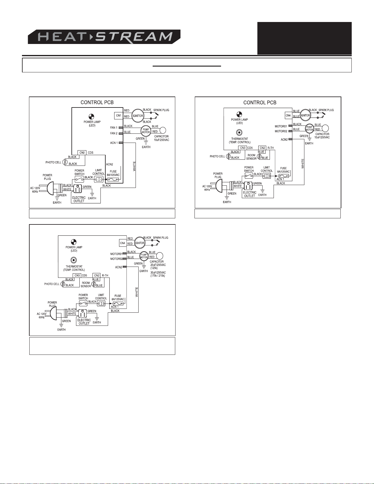
Wiring Diagrams
NEVER LEAVE HEATER
UNATTENDED WHILE BURNING OR WHILE CONNECTED
TO A POWER SOURCE
Figure 22: Model HS-45-KFA Figure 23: Model HS-70T-KFA
Figure 24: Model HS-125T / 175T / 215T-
KFA
© 2012, Pinnacle Products International, Inc.
14
Kerosene User’s Manual
Page 15

Troubleshooting
NEVER LEAVE HEATER
UNATTENDED WHILE BURNING OR WHILE CONNECTED
TO A POWER SOURCE
Problem
Heater fires, but Main PCB shuts
heater off after a short period of time.
Lamp is flickering, and LED display
shows “E1”.
Heater will not operate, or motor runs
for short time. Lamp flickers and LED
display shows “E1”.
Possible Cause Solution
1. Incorrect pump pressure
2. Dirty Input, Output or Lint Filter
3. Dirty Fuel Filter
4. Nozzle is Dirty
5. Photocell lens is Dirty
6. Photocell not installed properly
7. Photocell Defective
8. Improper electrical connection between
Main PCB and Photocell.
1. No kerosene in fuel tank
2. Incorrect pump pressure
3. Corroded Spark Plug or incorrect plug
gap.
4. Dirty Fuel Filter
5. Dirty Nozzle
6. Moisture in Fuel/Fuel Tank
7. Improper electrical connection between
Transformer and Circuit Board
8. Ignitor Wire not connected to Spark
Plug
9. Defective Ignitor
1. Adjust Pump Pressure (Page 11)
2. Clean/replace Air Filter (Page 9)
3. Clean/replace Fuel Filter (Page 11)
4. Clean/replace Nozzle (Page 10)
5. Clean/replace Photocell (Page 10)
6. Adjust Photocell position (Page 10)
7. Replace Photocell (Page 10)
8. Check wiring connections (See Wiring
Diagrams, Page 14)
1. Fill tank with fresh kerosene
2. Adjust Pump Pressure (Page 11)
3. Clean/replace Spark Plug (Page 10)
4. Clean/replace Fuel Filter (Page 11)
5. Clean/replace Nozzle (Page 10)
6. Rinse out fuel tank with clean fresh
kerosene (Page 9)
7. Inspect all electrical connections. See
Wiring Diagrams (Page 14)
8. Re-attach Ignitor wire to Spark Plug
(Page 10)
9. Replace Ignitor
Fan does not operate when heater is
plugged in and Power Switch is in the
“ON” position. The lamp is flickering or
on and LED Display shows “E1” or
“E2”.
Lamp is flickering, and LED display
shows “E3”
Poor Combustion and / or excess soot
production
Heater does not turn on and the lamp
is not lit
1. Thermostat is set too low (Does not
apply to HS-45-KFA)
2. Broken electrical connection between
Main PCB and motor
1. Thermostat Switch has failed 1. Replace Thermostat Switch. Wiring
1. Dirty Input, Output or Lint Filter
2. Dirty Fuel Filter
3. Poor quality of fuel
4. PSI is too high or too low
1. Temperature limit sensor has
overheated
2. No electrical power
3. Fuse Blown
4. Improper electrical connection between
Temperature Limit Sensor and Circuit
Board
1. Rotate thermostat to a higher setting
2. Inspect all electrical connections. See
Wiring Diagrams (Page 14)
Diagrams (Page 14
1. Clean/replace Air Filter (Page 9)
2. Clean/replace Fuel Filter (Page 10)
3. Be sure fuel is not contaminated or old
4. Use proper pressure (Page 11)
1. Push Power Switch to “OFF” and allow
heater to cool for 10 minutes. Push
Power Switch to back to “ON”
2. Check power cord and extension cord
to insure of proper connection. Test
power supply
3. Check/replace Fuse
4. Inspect all electrical connections. Wiring
Diagrams (Page 14)
)
© 2012, Pinnacle Products International, Inc.
15
Kerosene User’s Manual
Page 16

NEVER LEAVE HEATER
UNATTENDED WHILE BURNING OR WHILE CONNECTED
TO A POWER SOURCE
LIMITED WARRANTY
Pinnacle Products International, Inc. warrants this
heater to the original retail purchaser only, to be free from
defects in material and workmanship for a period of one
(1) year from the date of initial purchase. This product
must be properly installed, maintained and operated in
accordance with the instructions provided.
Pinnacle Products International, Inc. requires reasonable proof of your date of purchase from an authorized
retailer or distributor. Therefore, you should keep your
sales slip, invoice, or cancelled check from the original
purchase. This Limited Warranty shall be limited to the
repair or replacement of parts, which prove defective
under normal use and service within the warranty period,
and which Pinnacle Products International, Inc. shall
determine at its reasonable discretion.
This warranty does not apply to products purchased for
rental use.
This Limited Warranty does not cover any failures or operating difficulties due to normal wear and tear, accident,
abuse, misuse, alteration, misapplication, improper installation or improper maintenance and service by you or any
third party. Failure to perform normal and routine maintenance on the heater, shipping damage, damage related to
insects, birds, or animals of any kind, and damage due to
weather conditions are also not covered. In addition, the
Limited Warranty does not cover damage to the finish,
such as scratches, dents, discoloration, rust or other
weather damage, after purchase.
All transportation costs for the return of the damaged
product or parts will be the responsibility of the purchaser.
Upon receipt of damaged item, Pinnacle Products
International, Inc. will examine the item and determine if
defective. Pinnacle Products International, Inc. will
repair or replace and return the item, freight pre-paid. If
Pinnacle Products International, Inc. finds the item to be
in normal operating condition, or not defective, the
item will be returned freight collect.This Limited Warranty
is in lieu of all other express warranties. Pinnacle
Products International, Inc. disclaims all warranties for
products that are purchased from sellers other than
authorized retailers or distributors.
AFTER THE PERIOD OF THE ONE (1) YEAR EXPRESS
WARRANTY EXPIRES, Pinnacle Products International,
Inc. DISCLAIMS ANY AND ALL IMPLIED WARRANTIES,
INCLUDING WITHOUT LIMITATION THE IMPLIED WARRANTIES OF MERCHANTABILITY AND FITNESS FOR A
PARTICULAR APPLICATION. FURTHER, Pinnacle
Products International, Inc. SHALL HAVE NO LIABILITY
WHATSOEVER TO PURCHASER OR ANY THIRD PARTY
FOR ANY SPECIAL, INDIRECT, PUNITIVE, INCIDENTAL,
OR CONSEQUENTIAL DAMAGES. Pinnacle Products
International, Inc. assumes no responsibility for any
defects caused by third parties. This Limited Warranty
gives the purchaser specific legal rights; a purchaser may
have other rights depending upon where he or she lives.
Some states do not allow the exclusion or limitation of
special, incidental or consequential damages, or limitations
on how long a warranty lasts, so the above exclusion and
limitations may not apply to you.
Pinnacle Products International, Inc. does not authorize
any person or company to assume for it any other
obligation or liability in connection with the sale,
installation, use, removal, return, or replacement of its
equipment, and no such representations are binding on
Pinnacle Products International, Inc.
Always be sure to specify model number and serial
number when making any claim with Pinnacle Products
International, Inc. For your convenience use the space
provided below to list this information:
Model #: ____________________
Serial #: _________________________
Date of Purchase: _________________
Page 17

Manual del Usuario e
Instrucciones de Operación
Modelos No: HS-45-KFA, HS-70T-KFA, HS-125T-KFA,
HS-175T-KFA, HS-215T-KFA
CONSUMIDOR: Guarde este manual para futuras consultas.
SI NO CUMPLE CON LAS PRECAUCIONES Y LAS INSTRUCCIONES QUE SE LE PROPORCIONAN
CON ESTE CALENTADOR, PUEDE PROVOCAR LA MUERTE, LESIONES CORPORALES GRAVES,
Y PÉRDIDA DE LA PROPIEDAD O PELIGRO DE INCENDIO, EXPLOSIÓN O QUEMADURA, ASFIXIA,
ENVENENAMIENTO POR MONÓXIDO DE CARBONO, Y/O CHOQUE ELÉCTRICO.
ESTE CALENTADOR SOLAMENTE LO DEBEN USAR O DARLE MANTENIMIENTO LAS PERSONAS
QUE PUEDAN COMPRENDER Y SEGUIR LAS INSTRUCCIONES.
SI NECESITA AYUDA O INFORMACIÓN SOBRE EL CALENTADOR, TAL COMO UN MANUAL DE
INSTRUCCIONES, ETIQUETAS, ETCÉTERA, PÓNGASE EN CONTACTO CON EL FABRICANTE.
Éste es un calentador portátil sin ventilación. La unidad utiliza el aire (oxígeno) del área o zona donde se usa.
Página 8.
Fax: (215) 891-8461 • Sitio Web: www.heatstream.us • Correo electrónico: info@pinnacleint.com
Será necesario suministrar el aire adecuado de combustión y de ventilación. Consulte VENTILACIÓN en la
© Pinnacle Products International, Inc.
668 Stony Hill Road #302 Yardley, PA 19067 USA Teléfono gratuito: (800) 641-6996
Page 18

Tabla de contenidos
ADVERTENCIA
NUNCA DEJE DESATENDIDO EL
CALENTADOR MIENTRAS ESTÉ
ENCENDIDO O MIENTRAS ESTÉ
CONECTADO A UNA FUENTE DE
ALIMENTACIÓN
Información sobre seguridad ......................................... 2-3
Desempaque ..................................................................... 3
Características .................................................................. 4
Montaje ........................................................................... 5-6
Operación ....................................................................... 7-9
Teoría de Operación ......................................................... 7
Ventilación ......................................................................... 8
Información sobre seguridad
ADVERTENCIA
EXPLOSIÓN. MANTENGA LOS COMBUSTIBLES SÓLIDOS COMO, POR EJEMPLO,
MATERIALES DE CONSTRUCCIÓN, PAPEL Y
CARTÓN, A UNA DISTANCIA PRUDENCIAL
DEL CALENTADOR SEGÚN LO RECOMIENDAN LAS INSTRUCCIONES. NUNCA USE EL
CALENTADOR EN ESPACIOS QUE CONTENGAN O PUEDAN CONTENER COMBUSTIBLES VOLÁTILES O EN SUSPENSIÓN
EN EL AIRE NI PRODUCTOS COMO, POR
EJEMPLO, GASOLINA, DISOLVENTES, SOLVENTES DE PINTURA, PARTÍCULAS DE
POLVO O QUÍMICOS DESCONOCIDOS.
ADVERTENCIA
RECREATIVO NI TIENDAS.
ADVERTENCIA
instrucciones de seguridad y operación.
Residentes de California: Los productos derivados de
la combustión que produce este producto contienen monóxido
de carbono, un compuesto químico que el estado de California
reconoce como causante de cáncer y malformaciones congénitas (y otros daños del sistema reproductor).
Residentes de Massachusetts: La ley del Estado
de Massachusetts prohíbe el uso de este calentador en
cualquier edificio que se utilice total o parcialmente para la
habitación humana. El uso de este dispositivo de calefacción en
Massachusetts requiere la autorización del departamento de
bomberos de la localidad (M.G.L.C. 148, Sección 10A).
Residentes de la Ciudad de Nueva York: El
Código de Incendios de la Ciudad de Nueva York prohíbe el
almacenamiento, la manipulación y el uso de calentadores alimentados por keroseno para calentamiento de espacios.
Cualquier persona que infrinja esa disposición estará sujeta a
una multa de hasta 10,000 dólares y una pena de prisión de
hasta 6 meses.
Biodiesel dañará el filtro y sellos. La garantía no cubrirá
cualquier daño causado por el uso de Biodiesel.
PELIGRO DE INCENDIO, QUEMADURAS, INHALACIÓN Y
NO DEBE USARSE EN CASAS,
VEHÍCULOS DE USO
No use este calentador hasta que haya
leído y entendido totalmente estas
Este calefactor no es adecuado para
usarse con Biodiesel; el uso de
Almacenamiento a largo plazo .......................................... 9
Mantenimiento .............................................................. 9-11
Dibujo de despiece de piezas .......................................... 12
Lista de Recambios .................................................... 12-13
Diagramas eléctricos ....................................................... 14
Guía de solución de problemas ....................................... 15
Garantía ....................................................... Contraportada
Indica una situación de peligro inminente que, de no evitarse, CAUSARÁ
la muerte o una lesión grave.
Indica una situación de posible peligro que, de no evitarse, PODRÍA
causar la muerte o una lesión grave.
CAUTION
causar lesiones leves o moderadas.
Éste es un calentador de keroseno, de tiro forzado, de acción
directa. Está diseñado principalmente para uso como un
calentador temporal en edificios en construcción, alteración o
reparación. Acción directa significa que todos los productos de
combustión del calentador ingresan en el espacio que se está
calentando. Este aparato tiene una eficiencia de combustión del
98%, pero produce pequeñas cantidades de monóxido de
carbono. El monóxido de carbono es tóxico.
Los humanos pueden tolerar pequeñas cantidades de monóxido
de carbono, y por tanto, deben tomarse las medidas de precaución necesarias para suministrar una ventilación adecuada. No
proporcionar la ventilación adecuada de acuerdo con este manual
puede ocasionar la muerte. Las primeras etapas de intoxicación
por monóxido de carbono producen síntomas similares a los de la
gripe. Los síntomas de una ventilación inadecuada son los siguientes:
dolor de cabeza *mareo *irritación de la nariz y los
*
ojos *náusea *boca seca *irritación de la garganta
Para obtener el mejor rendimiento de este calentador, se sugiere
muy enfáticamente utilizar el combustible keroseno 1-K. El
keroseno 1-K ha sido refinado para prácticamente eliminar los
contaminantes como el sulfuro, el cual puede producir un olor a
huevos podridos durante el funcionamiento del calentador. Sin
embargo, también se puede utilizar el aceite combustible No. 1 o
No. 2 (combustible diesel) si el keroseno 1-K no está disponible.
Tenga en mente que estos combustibles no queman tan limpio
como el keroseno 1-K, y por tanto, se debe proporcionar una
mayor ventilación de aire fresco para compensar contra los contaminantes adicionales que podrían agregarse al espacio calentado. El uso del aceite combustible No. 1 o No. 2 puede hacer
necesario un mantenimiento periódico más frecuente.
Indica una situación de posible peligro que, de no evitarse, PODRÍA
¡La intoxicación por monóxido de
carbono puede producir la muerte!
© 2012, Pinnacle Products International, Inc.
2
Manual del usuario del calentador a keroseno
Page 19

NUNCA DEJE DESATENDIDO EL
CALENTADOR MIENTRAS ESTÉ
ENCENDIDO O MIENTRAS ESTÉ
CONECTADO A UNA FUENTE DE
ALIMENTACIÓN
Información sobre seguridad (continuación)
¡Riesgo de contaminación del aire interior!
- ¡Utilice este calentador sólo en áreas bien ventiladas!
Proporcione una abertura de al menos 2,800 cm cuadrados
(tres pies cuadrados) de aire fresco exterior por cada 100,000
BTU/Hr de capacidad útil del calentador.
- Las personas con problemas respiratorios deberían consultar
con un médico antes de usar el calentador.
- Intoxicación por monóxido de carbono: Los síntomas iniciales
de la intoxicación por monóxido de carbono se parecen a los
síntomas de la gripe como dolor de cabeza, mareo y/o
náusea. Si usted presenta estos síntomas, es posible que su
calentador no esté funcionando correctamente.
- ¡Respire inmediatamente aire fresco! Haga que le reparen el
calentador. El monóxido de carbono afecta más a unas personas que a otras: Estas incluyen las mujeres embarazadas,
aquellos con enfermedades del pulmón o corazón, anemia, o
aquellos que estén bajo la influencia del alcohol o a altas
alturas o elevaciones.
¡Riesgo de quemaduras, incendio y/o
explosión!
- NUNCA use combustibles como gasolina, bencina, solventes
de pintura u otros compuestos de aceite en este calentador
(RIESGO DE INCENDIO O EXPLOSIÓN).
- NUNCA llene el tanque de combustible del calentador mientras
esté funcionando o todavía esté caliente. Este calentador está
SUMAMENTE CALIENTE cuando está funcionando.
- Mantenga todos los materiales combustibles lejos del
calentador.
- NUNCA bloquee u obstruya la entrada de aire (en la parte
posterior) ni la salida de aire (en la parte anterior) del
calentador.
- NUNCA use conductos en las partes anterior o posterior del
calentador.
- NUNCA mueva o sujete el calentador cuando todavía esté
caliente.
- NUNCA transporte un calentador con combustible en su
tanque.
- Si está equipado con un termostato, el calentador podría
encenderse en cualquier momento.
- SIEMPRE coloque el calentador en una superficie estable y
nivelada.
- SIEMPRE mantenga a los niños y animales lejos del
calentador.
- El almacenamiento de combustible a granel deberá estar
situado a no menos de 7.62 metros (25 pies) de distancia de
calentadores, antorchas, generadores portátiles u otras
fuentes de ignición. Todo almacenamiento de combustible
deberá realizarse de acuerdo con las autoridades federales,
estatales o locales que tengan jurisdicción.
- Nunca use este calentador en áreas habitables o áreas para
dormir.
- NUNCA use este calentador donde puedan haber presentes
vapores inflamables.
¡Peligro de electrocución!
- Utilice únicamente la energía eléctrica (voltaje y frecuencia)
especificada en la placa de modelo del calentador. Utilice únicamente un cordón de extensión de tres puntas y una toma de
corriente para tres puntas conectada a tierra.
- SIEMPRE instale el calentador en forma que no esté directamente expuesto al agua rociada, lluvia, agua goteante o viento.
- SIEMPRE desconecte el calentador cuando no lo esté usando.
Separación mínima entre el calentador y materiales
combustibles (cm):
70k 125k 175k 215k
45k
Parte superior 122 122 122 122 122
Lados 122 122 122 122 122
Frente 244 244 244 244 305
Desempaque
Extraiga el calentador y todos los materiales de embalaje de la
caja de envío.
AVISO: Guarde la caja y los materiales de embalaje para almacenar la unidad en el futuro.
© 2012, Pinnacle Products International, Inc.
Consulte el cuadro que se da abajo para asegurarse que tiene
todas las piezas necesarias para armar su calentador. Si descubre que faltan piezas, llame al 215-891-8460 para solicitar
asistencia para recibir los componentes que faltan.
3
Manual del usuario del calentador a keroseno
Page 20

Características
Figura 1: Características de los Modelos HS-45/70T-KFA
NUNCA DEJE DESATENDIDO EL
CALENTADOR MIENTRAS ESTÉ
ENCENDIDO O MIENTRAS ESTÉ
CONECTADO A UNA FUENTE DE
ALIMENTACIÓN
Figura 2: Características del Modelo HS-125T / 175T / 215T-KFA
HS-45-KFA HS-70T-KFA HS-125T-KFA HS-175T-KFA HS-215T-KFA
CONSUMO DE
COMBUSTIBLE
(G/HORA)
.35 .53 .95 1.34 1.63
Figura 3: Especificaciones
© 2012, Pinnacle Products International, Inc.
4
Manual del usuario del calentador a keroseno
Page 21

NUNCA DEJE DESATENDIDO EL
CALENTADOR MIENTRAS ESTÉ
ENCENDIDO O MIENTRAS ESTÉ
CONECTADO A UNA FUENTE DE
ALIMENTACIÓN
Montaje
HS-45-KFA HS-70T-KFA HS-125T-KFA HS-175T-KFA HS-215T-KFA
Armazón de soporte de las ruedas NO NO SÍ SÍ SÍ
Rueda (2 piezas) NO NO SÍ SÍ SÍ
Asideros frontal y posterior NO NO SÍ SÍ SÍ
Eje NO NO SÍ SÍ SÍ
Asidero superior SÍ SÍ NO NO NO
Tornillos y tuercas (A) 8 de cada uno NO NO SÍ SÍ SÍ
Tornillos y tuercas (B) 4 de cada uno SÍ SÍ NO NO NO
Tuercas de la rueda, bujes NO NO SÍ SÍ SÍ
Enrolla cable SÍ SÍ SÍ SÍ SÍ
Asidero
No. de parte del juego de
herrajes: 70-056-0100
(HS-45 / 70T-KFA)
Enrolla
cables
Screws and
Nuts(4 ea.)
Ruedas
Figura 4: Componentes de Herrajes
Armazón de soporte de las ruedas
Asidero frontal
Herrajes de los componentes
Tuercas de
la rueda
del armazón
Bujes
Pasador de aletas, tornillos y tuercas (4 cada uno) y enrolla cables
No. de parte del juego de herrajes:
70-056-0210
(HS-125T/ 175T / 215T-KFA)
Asidero posterior
Eje
Figura 5: Componentes del Armazón, Modelos HS-125T / 175T / 215T-KFA
© 2012, Pinnacle Products International, Inc.
5
Manual del usuario del calentador a keroseno
Page 22

Montaje (continuación)
NUNCA DEJE DESATENDIDO EL
CALENTADOR MIENTRAS ESTÉ
ENCENDIDO O MIENTRAS ESTÉ
CONECTADO A UNA FUENTE DE
ALIMENTACIÓN
SÓLO PARA LOS MODELOS HS-45/70T-KFA
- Herramientas necesarias: Destornillador Phillips mediano.
MONTAJE DEL ASIDERO
1.Alinee los orificios en el alojamiento superior con los 2 orificios
en el asidero, como se muestra en la Figura 6.
2. Inserte tornillos y apriételos firmemente con un destornillador.
Asidero
Tornillo
Figura 6: Montaje del Asidero, Modelos HS45/70T-KFA
MONTAJE DEL ENROLLA CABLE
1. Alinee los agujeros en la coraza con aquellos en la cubierta
lateral e inserte las lengüetas del enrolla cable en el soporte de
la coraza.
2. Inserte tornillos y apriételos firmemente con un destornillador.
5. Agarre el asidero frontal y alinee los agujeros de montaje con
los agujeros correspondientes en el reborde del tanque y el
armazón para las ruedas. Inserte un tornillo (A) a través de los
agujeros y póngale una tuerca, pero no la apriete. Repita para
los otros 3 agujeros, luego apriete totalmente todos los 4
tornillos y tuercas.
6. Repita este proceso con el asidero posterior.
AVISO: El asidero frontal es más largo que el asidero posterior.
MONTAJE DEL ENROLLA CABLE
1. Alinee los agujeros en el enrolla cable con los agujeros correspondientes en el asidero posterior. Inserte tornillos (B) a
través de los agujeros, instale tuercas y apriételas (véase la
Figura 7).
No use el calentador sin el armazón de
soporte completamente montado en el
tanque.
SÓLO PARA LOS MODELOS HS-125T / 175T /
215T-KFA
- Herramientas necesarias: : Destornillador Phillips mediano,
llave ajustable o de extremo abierto de 5/16 pulgada, alicates
MONTAJE DEL ARMAZÓN Y LAS RUEDAS
1. Deslice el eje a través de los agujeros en el armazón de
soporte de las ruedas. Deslice los bujes y arandela plana (A)
para las ruedas en cada extremo del eje.
2. Deslice las ruedas en cada extremo del eje, y asegúrese que
el vástago de la válvula (si son neumáticas) esté hacia afuera
(véase la Figura 7).
3. Instale una tuerca de la rueda en el eje roscado y apriete.
4. Coloque el calentador en el armazón ya armado, y asegúrese
que el extremo de la entrada de aire esté situado donde están
las ruedas, y los agujeros de montaje en el reborde del tanque
del calentador estén alineados con los agujeros en el
armazón.
© 2012, Pinnacle Products International, Inc.
Figura 7 Montaje de los Modelos HS-125T/
175T/ 215T-KFA
6
Manual del usuario del calentador a keroseno
Page 23

Operación
KEROSENO (1-K)
Para obtener el mejor rendimiento de este calentador, se sugiere
muy enfáticamente utilizar el combustible keroseno 1-K. El
keroseno 1-K ha sido refinado para prácticamente eliminar los
contaminantes como el sulfuro, el cual puede producir un olor a
huevos podridos durante el funcionamiento del calentador. Sin
embargo, también se puede utilizar el aceite combustible No. 1 o
No. 2 (combustible diesel) si el keroseno 1-K no está disponible.
Tenga en mente que estos combustibles no queman tan limpio
como el keroseno 1-K, y por tanto, se debe proporcionar una
mayor ventilación de aire fresco para compensar contra los
contaminantes adicionales que podrían agregarse al espacio
calentado. El uso de combustible diesel puede causar una
excesiva producción de hollín. NO utilice ningún combustible
que no esté aprobado arriba.
AVISO: El keroseno debe almacenarse únicamente en un
contenedor azul que esté claramente identificado con la palabra
“keroseno”. Nunca almacene keroseno en un contenedor rojo. El
color rojo se asocia con la gasolina.
- NUNCA almacene keroseno en el área habitable. El keroseno
debe almacenarse en un área bien ventilada, situada fuera del
espacio habitable.
- NUNCA use un combustible como gasolina, bencina, alcohol,
gas blanco, combustible para hornos de campamento, solventes
de pintura u otros compuestos de aceite en este calentador
(ESTOS SON COMBUSTIBLES VOLÁTILES QUE PUEDEN
CAUSAR INCENDIOS O EXPLOSIONES).
- NUNCA almacene el keroseno expuesto directamente a la luz
solar ni cerca de cualquier fuente de calor.
- NUNCA utilice keroseno que se haya tenido almacenado de una
temporada a la siguiente. El keroseno se deteriora con el paso
del tiempo. EL KEROSENO ANTIGUO O VIEJO NO QUEMARÁ
ADECUADAMENTE EN ESTE CALENTADOR.
- Utilice keroseno 1-K en este calentador. El combustible No. 1 es
un sustituto adecuado.
TEORÍA DE FUNCIONAMIENTO
Sistema de combustible: Este calentador está equipado con
una bomba de aire que funciona por medio del motor eléctrico.
La bomba fuerza el aire a través de la línea de aire que está
conectada al tanque de combustible y el combustible avanza
hacia la boquilla en el cabezal del quemador. El aire también
pasa a través de la boquilla, donde se mezcla con el
combustible, y la mezcla es rociada en la cámara de combustión
como un fino rocío.
Ignición rápida de llama: Un transformador suministra un
voltaje alto a una bujía de dos puntas. La chispa enciende la
mezcla de combustible y aire en el momento en que es rociado
dentro de la cámara de combustión.
NUNCA DEJE DESATENDIDO EL
CALENTADOR MIENTRAS ESTÉ
ENCENDIDO O MIENTRAS ESTÉ
CONECTADO A UNA FUENTE DE
ALIMENTACIÓN
Figura 8 Teoría de Funcionamiento
Sistema de aire: El motor para trabajo pesado hace girar el
ventilador y éste fuerza el aire alrededor y hacia el interior de la
cámara de combustión, donde es supercalentado y finalmente
expulsado a través de la parte anterior de la cámara.
Control de límite de temperatura: Este calentador está equipa-
do con un Control de límite de temperatura, diseñado para apagar el
calentador si la temperatura interna sube a un nivel peligroso. Si este
dispositivo se activa y apaga su calentador, es posible que necesite
servicio.
Una vez que la temperatura cae por debajo de la temperatura de
reposición, usted podrá encender su calentador.
Protección del sistema eléctrico: El sistema eléctrico del
calentador está protegido con un cortacircuito que protege los
componentes del sistema contra daño. Si el calentador falla,
revise primero el fusible y reemplácelo si es necesario.
Sensor de llama: El calentador utiliza una fotocélula para “ver”
la llama en la cámara de combustión. En el caso de que la llama
se apague, el sensor detendrá la corriente eléctrica y el
calentador se apagará.
CÓMO LLENAR COMBUSTIBLE EN EL CALENTADOR
NUNCA LLENE EL TANQUE DE
COMBUSTIBLE EN UN LUGAR
INTERIOR. SIEMPRE LLENE EL TANQUE AFUERA.
ASEGÚRESE QUE EL CALENTADOR ESTÉ EN UN SUELO
NIVELADO CUANDO LLENE DE COMBUSTIBLE, Y NUNCA
LLENE EL TANQUE DE COMBUSTIBLE DEMASIADO.
NUNCA LLENE DE COMBUSTIBLE ESTE
CALENTADOR MIENTRAS ESTÉ
CALIENTE O EN FUNCIONAMIENTO. ESO PUEDE
OCASIONAR UN INCENDIO O UNA EXPLOSIÓN.
Siempre es buena idea encender el calentador afuera en la
primera vez. Esto permitirá quemar en un entorno seguro
cualquier aceite utilizado en el proceso de fabricación. Este
quemado inicial deberá durar por lo menos 10 minutos.
© 2012, Pinnacle Products International, Inc.
7
Manual del usuario del calentador a keroseno
Page 24

Operación (continuación)
NUNCA DEJE DESATENDIDO EL
CALENTADOR MIENTRAS ESTÉ
ENCENDIDO O MIENTRAS ESTÉ
CONECTADO A UNA FUENTE DE
ALIMENTACIÓN
VENTILACIÓN
Riesgo de contaminación del aire interior. Utilice el calentador sólo en áreas bien ventiladas.
En el espacio que busca calentar, proporcione una entrada de
aire fresco de al menos 2,800 cm2 (3 pies2) por cada 100,000
Btu/h de salida del calentador. Proporcione una abertura más
grande si se utilizan más calentadores. Por ejemplo, un
calentador HS-215T-KFA requerirá:
- dejar abierta 15.2 cm (6 pulg.) una puerta de garaje para dos
vehículos, o
- dejar abierta 22.9 cm (9 pulg.) una puerta de garaje para un solo
vehículo, o
- dejar abiertas 38.1 cm (15 pulg.) dos ventanas de 81.3 cm. (32
pulg.) de ancho.
PARA ENCENDER EL CALENTADOR
1. Llene el tanque de keroseno hasta que el indicador de com-
bustible indique “F”.
2. Asegúrese que la tapa del tanque de combustible esté bien
apretada.
3. Enchufe el cordón de alimentación eléctrica en un cordón de
extensión de tres puntas con conexión a tierra y luego enchufe
el cordón de extensión en una toma de corriente de 120V, de
tres puntas, conectada a tierra. El cordón de extensión deberá
ser de 182.9 cm (seis pies) de largo como mínimo.
- Los requisitos de tamaño de conductor para el cordón de
extensión son los siguientes:
› 1.8 a 3 metros (6 a 10 pies), utilice alambre 18 AWG.
› 3.4 a 30.4 metros (11 a 100 pies), utilice alambre 16 AWG.
› 30.8 a 61 metros (101 a 200 pies), utilice alambre 14 AWG.
AVISO: El indicador de temperatura ambiente (125/175/215 únicamente) indicará lo siguiente:
- Cuando la temperatura es inferior a 0° F, el indicador mostrará
“LO” (baja).
- Cuando la temperatura es superior a 37.2° C (99° F), el indicador mostrará “HI” (alta).
- Entre -17.8° y 37.2° C (0° y 99° F), el indicador mostrará la temperatura actual.
5. Si el calentador no enciende, es posible que el ajuste del ter-
mostato esté demasiado bajo. Gire la perilla de control del termostato a una temperatura más alta hasta que el calentador
se encienda. Si el calentador aún no enciende, ponga el interruptor de energía en la posición OFF (apagado) y luego en la
posición ON (encendido). Si el calentador aún no enciende,
consulte la Guía de solución de problemas en la Página 15.
AVISO: Los componentes eléctricos de este calentador están
protegidos por medio de un fusible que está montado en la placa
de circuitos impresos. Si el calentador no se enciende, revise
primero este fusible, y reemplácelo si es necesario. También
revise la fuente de alimentación eléctrica para asegurarse que el
voltaje correcto esté siendo suministrado al calentador.
PARA APAGAR EL CALENTADOR
Sencillamente lleve el interruptor a la posición OFF (apagado) y
desenchufe el cordón de alimentación eléctrica.
PARA VOLVER A ENCENDER EL CALENTADOR
1. Espere diez segundos después de apagar el calentador.
2. Ponga el interruptor de energía en la posición ON (encendido).
3. Asegúrese de acatar todas las precauciones del procedimiento
de arranque
TOMA DE CORRIENTE ELÉCTRICA
Modelos HS-70T / 125T / 175T /
215T-KFA
Modelo HS-45-KFA
Figura 9: Panel de Control para todos los
Modelos
4. Gire la perilla de control del termostato al ajuste de temperatura deseado (70/125/175/215 únicamente). El rango de ajustes
es de 4.44° C a 43.3° C (40° F a 110°F). Ponga el interruptor
de energía en la posición ON (encendido) (véase la Figura 9).
La lámpara de indicación de energía y el indicador de temperatura ambiente (125/175/215 únicamente) se iluminarán y el
calentador se encenderá.
© 2012, Pinnacle Products International, Inc.
¡Peligro de descarga eléctrica!
- Nunca enchufe un aparato eléctrico con una capacidad de más
de 5 amperios en esta toma de corriente eléctrica.
- Siempre mantenga cubierta la toma de corriente cuando no se
utilice.
Cajón de almacenamiento
(excepto en los modelos
HS-45 / 70T-KFA)
Toma de corriente eléctrica
(120V 5 amperios máximo sin fusión)
Figura 10: Detalle de la Toma de Corriente
Eléctrica
8
Manual del usuario del calentador a keroseno
Page 25

Agarre del tapón
Tapón de
drenaje
NUNCA DEJE DESATENDIDO EL
CALENTADOR MIENTRAS ESTÉ
ENCENDIDO O MIENTRAS ESTÉ
CONECTADO A UNA FUENTE DE
ALIMENTACIÓN
Operación (continuación)
4. Para reinstalarlo, presione e inserte completamente el cabezal
de drenaje en el orificio de drenaje, y luego presione e inserte
completamente la tapa de sellado en el orificio del cabezal de
drenaje para fijar éste en posición (véase la Figura 12).
IMPORTANTE: Nunca almacene el keroseno sobrante
durante el verano. El uso de todo combustible antiguo
puede dañar su calentador.
Tanque de combustible
Tapón de drenaje
Figura 11: Extracción del Tapón de Drenaje
ALMACENAMIENTO A LARGO PLAZO
Drene el tanque de combustible
1. En los modelos HS-45 / 70T-KFA, drene el combustible a
través de la abertura de la tapa del tanque de combustible,
usando un sifón aprobado. En los modelos HS-125 / 175 /
215-KFA, drene el combustible a través del Tapón de drenaje
que está en la parte inferior del Tanque de combustible.
2. Para extraer el tapón de drenaje (125 / 175 / 215), tire del
agarre del tapón hacia abajo y extraiga el cabezal de sellado
del orificio de drenaje en el tanque (véase la Figura 11).
3. Con una pequeña cantidad de keroseno, enjuague y
arremoline el keroseno dentro del tanque de combustible.
Vacíe completamente el tanque.
Mantenimiento
Nunca realice el mantenimiento del calentador mientras esté enchufado o caliente.
Utilice únicamente piezas de repuesto auténticas para el equipo.
El uso de componentes alternativos o de terceros puede causar
condiciones peligrosas de funcionamiento y anulará su garantía.
Le sugerimos seguir un programa de mantenimiento como el
siguiente:
COMBUSTIBLE Y TANQUE DE COMBUSTIBLE:
Purgue el tanque después de cada 200 horas de funcionamiento
o según sea necesario. No use agua para purgar el tanque.
Utilice únicamente keroseno 1-K fresco.
FILTROS DE AIRE:
El Filtro de entrada de aire debe reemplazarse o lavarse con
Filtro de salida
de aire
Filtro de
entrada
Cabezal de sellado
Brida del cabezal
Brida del
cabezal
Brida de la tapa
Tapa de sellado
Figura 12: Reinstalación del Tapón de Drenaje
jabón y agua y secarse completamente después de cada 500
horas de funcionamiento, o menos, dependiendo de las condiciones.
Los Filtros de salida y de pelusas deben reemplazarse después
de cada 500 horas de funcionamiento o menos, dependiendo de
las condiciones.
AVISO: Es posible que se necesite un mantenimiento adicional
si se usa combustible diesel.
ASPAS DEL VENTILADOR:
Las aspas del ventilador deben limpiarse al menos una vez por
cada temporada de calefacción, dependiendo de las condiciones.
Limpie todas las acumulaciones de polvo y tierra con un trapo
húmedo, teniendo cuidado de no doblar ninguna de las aspas
del ventilador. Asegúrese que las aspas del ventilador estén
secas antes de volver a encender el calentador. Para desmontar
el ventilador, véase la Figura 14.
Tornillo de
fijación
Eje del
motor
Filtro de pelusas
Cubierta del filtro extremo
Figura 13: Reemplazo de los Filtros
© 2012, Pinnacle Products International, Inc.
Aspa del
ventilador
Figura 14: Reemplazo del Ventilador
9
Manual del usuario del calentador a keroseno
Page 26

Mantenimiento (continuación)
NUNCA DEJE DESATENDIDO EL
CALENTADOR MIENTRAS ESTÉ
ENCENDIDO O MIENTRAS ESTÉ
CONECTADO A UNA FUENTE DE
ALIMENTACIÓN
BOQUILLAS:
Las boquillas deben limpiarse o reemplazarse al menos una vez
por cada temporada de calefacción. El combustible contaminado
podría hacer esto inmediatamente necesario.
Para limpiar la suciedad de la boquilla, sople aire comprimido a
través del frente de la boquilla. Es posible que sea necesario
remojar la boquilla en keroseno 1-K limpio para facilitar el
aflojamiento de las partículas.
AVISO: Es posible que se necesite un mantenimiento adicional
si se usa combustible diesel. El uso de este calentador sin un
mantenimiento adecuado o con combustible contaminado o
antiguo podría dar lugar a una combustión inadecuada y una
posible producción de hollín. ASEGÚRESE DE UTILIZAR UN
COMBUSTIBLE APROBADO (consulte OPERACIÓN en la
página 6).
Cabezal del quemador
Tornillo
Bujía
Conductor del
encendedor
Manguera de la línea de
combustible
Manguera de la línea de aire
BUJÍA:
Límpiela y reajuste la separación entre los electrodos de la bujía
después de cada 600 horas de funcionamiento, o reemplácela
según sea necesario. Después de extraer la bujía, limpie las terminales con una escobilla metálica. Reajuste la separación de
las terminales (o electrodos) a 3.5 mm (0.140 pulg).
Conductor del encendedor
Bujía
Cabezal del
quemador
Separación
Figura 16: Reemplazo de la Bujía
FOTOCÉLULA:
La fotocélula debe limpiarse al menos una vez por cada temporada de calefacción o más, dependiendo de las condiciones.
Utilice un hisopo de algodón remojado en agua o alcohol para
limpiar la lente de la fotocélula. Observe la posición correcta de
la fotocélula, tal como se indica en la Figura 17 y la Figura 18.
Fotocélula
Cabezal del quemador
Boquilla
Cara de la
boquilla
Conector de la línea
Conector de la línea de aire
de combustible
Figura 15: Reemplazo de la Boquilla
© 2012, Pinnacle Products International, Inc.
Lente de la
fotocélula
Instalación de la fotocélula:
1) Incorrecto
2) Correcto
Figura 17: Posición de la Fotocélula
10
Manual del usuario del calentador a keroseno
Page 27

Conductor de
la fotocélula
NUNCA DEJE DESATENDIDO EL
CALENTADOR MIENTRAS ESTÉ
ENCENDIDO O MIENTRAS ESTÉ
CONECTADO A UNA FUENTE DE
ALIMENTACIÓN
Mantenimiento (continuación)
AJUSTE DE LA PRESIÓN DE LA BOMBA:
Mientras el calentador está funcionando, gire la válvula de
seguridad hacia la derecha para aumentar, o hacia la izquierda
para disminuir (véase la Figura 20). Utilice un destornillador de
punta plana para girar la válvula. A continuación se muestra la
presión correcta de la bomba:
Núm. de modelo Presión de la bomba
Panel de circuitos
Sólo el
HS-70T-KFA
Figura 18: Posición de la Fotocélula para los
Modelos HS-45 / 70T-KFA
FILTRO DE COMBUSTIBLE:
El filtro de combustible debe limpiarse al menos dos veces por
cada temporada de calefacción, enjuagándolo con keroseno 1-K
limpio. El combustible contaminado podría hacer esto
inmediatamente necesario (véase la Figura 19).
AVISO: Para extraer el filtro de los modelos HS-45 / 70T-KFA,
gire el filtro 90º hacia la derecha. Para extraer el filtro de los
modelos HS-125T / 175T / 215T-KFA, gire el filtro 90º hacia la
izquierda.
Es posible que se necesite un mantenimiento adicional si se usa
combustible diesel.
ocasionar una mala combustión y producción de
hollín.
Conductor de la fotocélula
El mantenimiento inadecuado puede
HS-45-KFA 20.6 Kpa / 3.0 PSI
HS-70T-KFA 27.5 Kpa / 4.0 PSI
HS-125T-KFA 34.4 Kpa / 5.0 PSI
HS-175T-KFA 51.7 Kpa / 7.5 PSI
HS-215T-KFA 62.05 Kpa / 9.0 PSI
Tolerancia ± 10%
Para obtener la mejor medida de la presión, pruebe con el
tanque lleno de combustible. La presión es óptima cuan-
do el color del cono de la ojiva está rojo cereza y no
hay llamas que se extienden del calentador.
Tornillo
de ajuste
Panel de circuitos
Filtro de
combustible
Cubierta
lateral
Interruptor de energía
Tornillo
Línea de
combustible
Conductor del interruptor de
energía
Figura 19: Reemplazo del Filtro de Combustible
© 2012, Pinnacle Products International, Inc.
Figura 20: Ajuste de la Presión de la Bomba
11
Manual del usuario del calentador a keroseno
Page 28

Dibujo de despiece de piezas
NUNCA DEJE DESATENDIDO EL
CALENTADOR MIENTRAS ESTÉ
ENCENDIDO O MIENTRAS ESTÉ
CONECTADO A UNA FUENTE DE
ALIMENTACIÓN
Figura 21: Vista Detallada de los Modelos HS-45 / 70T / 125T / 175T / 215T-KFA
Lista de Recambios
No Número de Parte para los Modelos:
de Ref. Descripción HS-45-KFA HS-70T-KFA HS-125T-KFA HS-175T-KFA HS-215T-KFA
1 Conjunto del tanque de 70-002-0100 70-002-0100 70-002-0200 70-002-0300 70-002-0300
2 Tapón de drenaje – – 70-002-0105 70-002-0105 70-002-0105
3 Conjunto del indicador de 70-007-0110 70-007-0115 70-007-0210 70-007-0210 70-007-0215
4 Conjunto del filtro de 70-003-0100 70-003-0100 70-003-0200 70-003-0200 70-003-0200
5 Tapa del tanque de combustible 70-006-0100 70-006-0100 70-006-0100 70-006-0100 70-006-0100
6 Cordón de alimentación eléctrica 70-034-0100 70-034-0100 70-034-0200 70-034-0200 70-034-0200
7 Interruptor de energía 70-038-0100 70-038-0100 70-038-0100 70-038-0100 70-038-0100
© 2012, Pinnacle Products International, Inc.
combustible
combustible
combustible
12
Manual del usuario del calentador a keroseno
Page 29

NUNCA DEJE DESATENDIDO EL
CALENTADOR MIENTRAS ESTÉ
ENCENDIDO O MIENTRAS ESTÉ
CONECTADO A UNA FUENTE DE
ALIMENTACIÓN
Lista de Recambios (continuación)
No. Número de Parte para los Modelos
de Ref. Descripción HS-45-KFA HS-70T-KFA HS-125T-KFA HS-175T-KFA HS-215T-KFA
8 Ventana de visualización – – 70-040-0100 70-040-0100 70-040-0100
9 Perilla de control del termostato – 70-031-0100 70-031-0100 70-031-0100 70-031-0100
10 Coraza inferior – – – – –
11 Línea de aire 70-035-0100 70-035-0200 70-035-0300 70-035-0400 70-035-0500
12 Control de límite del termostato 70-019-0100 70-019-0100 70-019-0100 70-019-0100 70-019-0200
13 Conjunto de la cámara de 70-011-0100 70-011-0200 70-011-0300 70-011-0400 70-011-0500
14 Soporte de la fotocélula 70-010-0101 70-010-0101 70-010-0101 70-010-0101 70-010-0101
15 Línea de combustible 70-036-0100 70-036-0200 70-036-0300 70-036-0400 70-036-0500
16 Conjunto de la fotocélula 70-016-0100 70-016-0100 70-016-0100 70-016-0100 70-016-0100
17 Conjunto del cabezal 70-014-0100 70-014-0200 70-014-0300 70-014-0400 70-014-0500
18 Juego de boquilla 70-015-0100 70-015-0200 70-015-0300 70-015-0400 70-015-0500
19 Arandela del sello de la boquilla – – – – –
20 Resorte del sello de la boquilla – – – – –
21 Manguito de la boquilla – – – – –
22 Cabezal del quemador – – – – –
23 Juego de bujía 70-052-0100 70-052-0100 70-052-0200 70-052-0200 70-052-0200
24 Conjunto del motor y la bomba 70-020-0100 70-020-0100 70-020-0300 70-020-0400 70-020-0500
25 Motor 70-021-0500 70-021-0500 70-021-0510 70-021-0520 70-021-0520
26 Cuerpo de la bomba 70-020-0101 70-020-0101 70-020-0101 70-020-0101 70-020-0401
27 Juego de rotor 70-022-0100 70-022-0100 70-022-0100 70-022-0100 70-022-0200
28 Aspa – – – – –
29 Cubierta extrema de la bomba 70-020-0102 70-020-0102 70-020-0102 70-020-0102 70-020-0102
30 Juego de filtro 70-054-0100 70-054-0100 70-054-0100 70-054-0100 70-054-0100
31 Filtro de pelusas – – – – –
32 Filtro de salida – – – – –
33 Cubierta del filtro extremo 70-020-0103 70-020-0103 70-020-0103 70-020-0103 70-020-0103
34 Juego de ajuste de la 70-055-0100 70-055-0100 70-055-0100 70-055-0100 70-055-0100
35 Bola – – – – –
36 Resorte – – – – –
37 Tornillo de ajuste – – – – –
38 Niple 70-014-0104 70-014-0104 70-014-0104 70-014-0104 70-014-0104
39 Capacitor 70-020-0125 70-020-0125 70-020-0200 70-020-0201 70-020-0201
40 Conjunto del ventilador 70-024-0100 70-024-0200 70-024-0300 70-024-0400 70-024-0400
41 Encendedor 70-037-0300 70-037-0300 70-037-0300 70-037-0300 70-037-0300
42 Cubierta del lado derecho 70-008-0100 70-008-0200 70-008-0300 70-008-0400 70-008-0450
43 Cubierta del lado izquierdo 70-009-0100 70-009-0100 70-009-0200 70-009-0300 70-009-0300
44 Protección del ventilador 70-016-0700 70-016-0700 70-016-0200 70-016-0200 70-016-0220
45 Conjunto de la placa de 70-027-0100 70-027-0200 70-027-0300 70-027-0300 70-027-0300
46 Fusible 70-027-0101 70-027-0101 70-027-0101 70-027-0101 70-027-0101
47 Tuerca de enganche 70-001-0105 70-001-0105 70-001-0105 70-001-0105 70-001-0105
48 Coraza superior – – – – –
49 Caja de almacenamiento – – 70-053-0100 70-053-0100 70-053-0100
50 Buje ojal 70-017-0100 70-017-0100 70-017-0100 70-017-0100 70-017-0100
51 Tapa del receptáculo 70-030-0100 70-030-0100 70-030-0100 70-030-0100 70-030-0100
52 Manómetro 70-025-0100 70-025-0100 70-025-0100 70-025-0100 70-025-0100
53 Buje del cordón 70-033-0100 70-033-0100 70-033-0200 70-033-0200 70-033-0200
54 Toma de corriente eléctrica 70-029-0100 70-029-0100 70-029-0100 70-029-0100 70-029-0100
55 Asidero 70-001-0103 70-001-0103 – – –
56 Asidero frontal – – 70-042-0100 70-042-0200 70-042-0200
57 Asidero posterior – – 70-043-0105 70-043-0205 70-043-0205
58 Armazón de soporte de – – 70-041-0101 70-041-0201 70-041-0201
59 Eje de las ruedas – – 70-041-0115 70-041-0205 70-041-0205
60 Rueda – – 70-041-0415 70-041-0415 70-041-0415
61 Tuerca de la rueda – – 70-041-0550 70-041-0550 70-041-0550
62 Juego de herrajes 70-056-0100 70-056-0100 70-056-0210 70-056-0210 70-056-0210
63 Enrolla cable 70-032-0100 70-032-0100 70-032-0200 70-032-0200 70-032-0200
combustión
del quemador
bomba/tapón
circuitos impresos principal
las ruedas
© 2012, Pinnacle Products International, Inc.
13
Manual del usuario del calentador a keroseno
Page 30

Diagramas eléctricos
NUNCA DEJE DESATENDIDO EL
CALENTADOR MIENTRAS ESTÉ
ENCENDIDO O MIENTRAS ESTÉ
CONECTADO A UNA FUENTE DE
ALIMENTACIÓN
Figura 22: Modelo HS-45-KFA Figura 23: Modelo HS-70T-KFA
Figura 24: Modelos HS-125T / 175T /
215T-KFA
© 2012, Pinnacle Products International, Inc.
14
Manual del usuario del calentador a keroseno
Page 31

Guía de solución de problemas
NUNCA DEJE DESATENDIDO EL
CALENTADOR MIENTRAS ESTÉ
ENCENDIDO O MIENTRAS ESTÉ
CONECTADO A UNA FUENTE DE
ALIMENTACIÓN
Problema
El calentador enciende pero la placa
de circuitos impresos principal apaga el
calentador después de un corto
período de tiempo. La lámpara
parpadea y la pantalla LED muestra
“E1”.
El calentador no funciona, o el motor
funciona por un corto tiempo. La
lámpara parpadea y la pantalla LED
muestra “E1”.
El ventilador no funciona cuando el
calentador está enchufado y el
interruptor de energía está en la
posición ON (encendido). La lámpara
parpadea o está encendida y la
pantalla LED muestra “E1” o “E2”.
La lámpara parpadea y la pantalla LED
muestra “E3”.
Mala combustión y/o producción
excesiva de hollín.
El calentador no se enciende y la
lámpara está apagada
Causa posible Solución
1. La presión de la bomba es incorrecta
2. El filtro de entrada, de salida o de
pelusas está sucio
3. El filtro de combustible está sucio
4. La boquilla está sucia
5. La lente de la fotocélula está sucia
6. La fotocélula está mal instalada
7. La fotocélula está defectuosa
8. Mala conexión eléctrica entre la placa de
circuitos impresos principal y la
fotocélula.
1. No hay keroseno en el tanque de combustible
2. La presión de la bomba es incorrecta
3. La bujía está oxidada o la separación
entre los electrodos de la bujía es
incorrecta
4. El filtro de combustible está sucio
5. La boquilla está sucia
6. Humedad en el combustible o en el
tanque de combustible
7. Mala conexión eléctrica entre el
transformador y la placa de circuitos
8. El conductor del encendedor no está
conectado a la bujía
9. El encendedor está defectuoso
1. El termostato está dispuesto a una
temperatura demasiado baja (no
aplica para el HS-45-KFA)
2. Conexión eléctrica interrumpida
entre la placa de circuitos impresos
principal y el motor.
1. El interruptor del termostato ha
fallado
1. El filtro de entrada, de salida o de
pelusas está sucio
2. El filtro de combustible está sucio
3. Mala calidad de combustible
4. La presión es demasiado alta o
demasiado baja
1. El sensor de límite de temperatura se ha
calentado demasiado
2. No hay energía eléctrica
3. Se ha quemado el fusible
4. Mala conexión eléctrica entre el sensor de
límite de temperatura y la placa de circuitos
1. Ajuste la presión de la bomba (Página 11)
2. Limpie o reemplace el filtro de aire (Página 9)
3. Limpie o reemplace el filtro de combustible
(Página 10)
4. Limpie o reemplace la boquilla (Página 9)
5. Limpie o reemplace la fotocélula (Página 10)
6. Ajuste la posición de la fotocélula (Página 10)
7. Reemplace la fotocélula (Página 10)
8. Revise las conexiones eléctricas (consulte los
Diagramas eléctricos en la Página 14)
1. Llene el tanque con keroseno fresco
2. Ajuste la presión de la bomba (Página 11)
3. Limpie o reemplace la bujía (Página 10)
4. Limpie o reemplace el filtro de
combustible (Página 10)
5. Limpie o reemplace la boquilla (Página 9)
6. Enjuague el interior del tanque con
keroseno fresco y limpio (Página 9)
7. Inspeccione todas las conexiones
eléctricas. Consulte los Diagramas
eléctricos (Página 14)
8. Vuelva a conectar el conductor del
encendedor en la bujía (Página 9)
9. Reemplace el encendedor
1. Gire el termostato a un ajuste más
alto
2. Inspeccione todas las conexiones
eléctricas. Consulte los Diagramas
eléctricos (Página 14)
1. Reemplace el interruptor del termostato. Diagramas eléctricos
(Página 14)
1. Limpie o reemplace el filtro de aire
(Página 9)
2. Limpie o reemplace el filtro de combustible (Página 10)
3. Asegúrese que el combustible no sea
viejo ni esté contaminado
4. Use la presión adecuada (Página 11)
1. Ponga el interruptor de energía en la posición
OFF (apagado) y deje que el calentador se
enfríe durante 10 minutos. Ponga el interruptor de energía nuevamente en la posición
ON (encendido).
2. Revise el cordón de alimentación y el cordón
de extensión para asegurarse que haya una
buena conexión eléctrica. Compruebe la
fuente de energía eléctrica.
3. Revise y reemplace el fusible si es necesario
4. Inspeccione todas las conexiones eléctricas.
Diagramas eléctricos (Página 14)
© 2012, Pinnacle Products International, Inc.
15
Manual del usuario del calentador a keroseno
Page 32

NUNCA DEJE DESATENDIDO EL
CALENTADOR MIENTRAS ESTÉ
ENCENDIDO O MIENTRAS ESTÉ
CONECTADO A UNA FUENTE DE
ALIMENTACIÓN
GARANTÍA LIMITADA
Pinnacle Products International, Inc. le garantiza
exclusivamente al comprador minorista original de este
calentador que no tendrá defectos de material ni mano de
obra por un período de un (1) año a partir de la fecha de
compra original. Este producto debe instalarse,
mantenerse y operarse correctamente de acuerdo con las
instrucciones suministradas.
Pinnacle Products International, Inc. requiere una
prueba razonable de su fecha de compra de un minorista
o distribuidor autorizado. Por lo tanto, usted debe guardar
su recibo de compra, factura o el cheque canjeado de la
compra original. Esta Garantía limitada se limita a la
reparación o el reemplazo de piezas que se comprueben
defectuosas en condiciones normales de uso y
mantenimiento dentro del período de garantía, y que
Pinnacle Products International, Inc. así determine a su
discreción razonable.
Esta garantía no se aplica a los productos adquiridos para
usar en alquiler.
Esta Garantía limitada no cubre ningún fallo ni dificultad
de funcionamiento debido a un desgaste normal,
accidente, abuso, mal uso, alteración, aplicación
incorrecta, instalación incorrecta o un mantenimiento y
servicio inadecuados realizados por usted o cualesquiera
terceros. Asimismo, la garantía no cubre el incumplimiento
de las revisiones de mantenimiento normales y regulares
del calentador, los daños sufridos durante el transporte,
los daños relacionados con insectos, aves o animales de
cualquier tipo, y los daños consecuencia de las
condiciones atmosféricas. Adicionalmente, la Garantía
limitada no cubre daños del acabado, como ralladuras,
abolladuras, cambios de color, oxidación u otros daños
ocasionados por las condiciones atmosféricas después de
la compra.
DESPUÉS DEL VENCIMIENTO DEL PERÍODO DE UN
(1) AÑO DE LA GARANTÍA LIMITADA, Pinnacle
Products International, Inc. DESCONOCERÁ
CUALESQUIERA Y TODAS LAS GARANTÍAS
IMPLÍCITAS, INCLUIDAS SIN LIMITACIONES LAS
GARANTÍAS IMPLÍCITAS DE COMERCIABILIDAD Y
ADECUACIÓN PARA UNA APLICACIÓN EN
PARTICULAR. ADEMÁS, Pinnacle Products
International, Inc. NO ASUME NINGUNA
RESPONSABILIDAD ANTE EL COMPRADOR O
CUALQUIER TERCERO POR CUALESQUIERA DAÑOS
ESPECIALES, INDIRECTOS, PUNITIVOS,
INCIDENTALES O CONSECUENTES. Pinnacle Products
International, Inc. no asume ninguna responsabilidad por
defectos causados por terceros. Esta Garantía limitada le
otorga derechos legales específicos al comprador, y es
posible que el comprador tenga otros derechos,
dependiendo del lugar donde viva. Algunos Estados no
permiten la exclusión ni limitación de daños especiales,
menores o indirectos, ni limitaciones de la duración de la
garantía; por lo que es posible que la exclusión y las
limitaciones anteriores no le conciernan a usted.
Pinnacle Products International, Inc. no autoriza a
ninguna persona o compañía a asumir a nombre de ella
cualquier otra obligación o responsabilidad relacionada
con la venta, instalación, uso, desmontaje, devolución o
reemplazo de su equipo y ninguna tal representación será
obligatoria para Pinnacle Products International, Inc.
Asegúrese siempre de especificar el número de modelo y
el número de serie cuando presente reclamos a Pinnacle
Products International, Inc. Para su comodidad, apunte
esta información en el espacio provisto:
Número de modelo: ____________________
Número de serie: ____________________
El comprador será responsable de todos los gastos de
transportación para la devolución del producto dañado o
piezas dañadas. Al recibir el artículo dañado, Pinnacle
Products International, Inc. lo examinará y determinará
si está defectuoso. Pinnacle Products International, Inc.
reparará o reemplazará y devolverá el artículo con porte
pagado. Si Pinnacle Products International, Inc. determina que el artículo está en condición normal de funcionamiento o no defectuoso, el artículo será devuelto con
flete por pagar. Esta Garantía limitada sustituye toda otra
garantía expresa. Pinnacle Products International, Inc.
excluye todas las garantías de los productos comprados
de otros vendedores que no sean minoristas o distribuidores autorizados.
Fecha de compra: ____________________
Page 33

Manuel de l’utilisateur et
instructions d’utilisation
Numéros de modèles: HS-45-KFA, HS-70T-KFA,
HS-125T-KFA, HS-175T-KFA, HS-215T-KFA
CLIENT : conserver ce manuel pour consultation ultérieure.
LE NON-RESPECT DES MISES EN GARDE ET DES INSTRUCTIONS FOURNIES AVEC CE
RADIATEUR PEUT ENTRAÎNER LA MORT, DE GRAVES BLESSURES ET DES PERTES
MATÉRIELLES OU DES DOMMAGES À LA PROPRIÉTÉ RÉSULTANT D’UN INCENDIE, D’UNE
EXPLOSION, DE BRÛLURES, D’ASPHYXIE, D’EMPOISONNEMENT AU MONOXYDE DE
CARBONE ET/OU D’UN CHOC ÉLECTRIQUE.
SEULES LES PERSONNES APTES À COMPRENDRE ET À SUIVRE LES INSTRUCTIONS
DEVRAIENT SE SERVIR DE CE RADIATEUR OU LE RÉPARER.
SI VOUS AVEZ BESOIN D’AIDE OU’INFORMATIONS CONCERNANT CE RADIATEUR, TELLES
QU’UNE NOTICE D’INSTRUCTIONS, UNE ÉTIQUETTE, ETC., PRIÈRE DE COMMUNIQUER
AVEC LE FABRICANT.
Cet appareil est un radiateur portatif non raccordé. Il utilise l’air (l’oxygène) de l’endroit où il se trouve. Il faut
page 8.
Télécopie: (215) 891-8461 • site Web: www.heatstream.us • Email: info@pinnacleint.com
assurer une quantité d’air de combustion et une ventilation adéquates. Se reporter à la section VENTILATION,
© Pinnacle Products International, Inc.
668 Stony Hill Road #302 Yardley, PA 19067 USA Numéro Vert: (800) 641-6996
Page 34

Table des matières
DANGER
DANGER
ADVERTENCIA
NE JAMAIS LAISSER LE RADIATEUR SANS SURVEILLANCE
ALORS QU’IL EST EN MARCHE OU
QU’IL EST RACCORDÉ À UNE
SOURCE D’ALIMENTATION.
Informations sur la sécurité ............................ 2-3
Déballage .......................................................... 3
Caractéristiques ................................................. 4
Assemblage .................................................... 5-6
Fonctionnement ................................................. 7
Combustibles ..................................................... 7
Principe de fonctionnement ............................... 7
Ventilation .......................................................... 8
Informations sur la sécurité
AVERTISSEMENT
D’EXPLOSION. GARDER LES COMBUSTIBLES SOLIDES, COMME LES
MATÉRIAUX DE CONSTRUCTION, LE PAPIER
OU LE CARTON, À UNE DISTANCE
SÉCURITAIRE DU RADIATEUR, SELON LES
RECOMMANDATIONS DE CE MANUEL. NE
JAMAIS UTILISER LE RADIATEUR DANS DES
ENDROITS QUI CONTIENNENT OU POURRAIENT CONTENIR DES MATIÈRES COMBUSTIBLES VOLATILES OU EN SUSPENSION
DANS L’AIR, OU ENCORE DES PRODUITS
COMME DE L’ESSENCE, DES SOLVANTS,
DES DILUANTS À PEINTURE, DES PARTICULES DE POUSSIÈRE OU DES PRODUITS
CHIMIQUES INCONNUS.
AVERTISSEMENT
DE PLAISANCE.
AVERTISSEMENT
sécurité et d’utilisation.
Résidents de la Californie: Les sous-produits de
combustion dégagés par cet appareil contiennent du monoxyde
de carbone, un produit chimique reconnu par l’État de Californie
comme causant le cancer et des malformations congénitales
(ou d’autres effets nocifs sur les organes reproductifs).
Résidents du Massachusetts: La législation de l’É-
tat du Massachusetts interdit l’utilisation de ce radiateur
dans tout édifice utilisé en tout ou en partie à des fins
d’habitation. L’utilisation de cet appareil de chauffage dans le
Massachusetts exige un permis du service d’incendie local
(M.G.L.C. 148. section 10A).
Résidents de la ville de New York : Le Code de
prévention des incendies de la ville de New York interdit l’entreposage, la manipulation et l’utilisation de radiateurs à kérosène
pour le chauffage localisé. Toute personne contrevenant à cette
disposition peut encourir une amende allant jusqu’à 10 000 dollars et une peine d’emprisonnement allant jusqu’à 6 mois.
Biodiesel dañará el filtro y sellos. La garantía no cubrirá
cualquier daño causado por el uso de Biodiesel.
RISQUE D’INCENDIE, DE
BRÛLURE, D’INHALATION ET
NE PAS UTILISER DANS DES
MAISONS OU DES VÉHICULES
Ne pas utiliser ce radiateur avant d’avoir lu
et entièrement compris ces directives de
Este calefactor no es adecuado para
usarse con Biodiesel; el uso de
Entreposage de longue durée ............................ 9
Entretien ....................................................... 9-11
Vue éclatée des pièces .................................... 12
Liste des pièces .......................................... 12-13
Schémas de câblage ....................................... 14
Dépannage ...................................................... 15
Garantie ............................................ Page verso
Indique un danger imminent qui, s’il
n’est pas évité, ENTRAÎNERA la mort
ou des blessures graves.
Indique un danger potentiel qui, s’il
n’est pas évité, PEUT entraîner la
mort ou des blessures graves.
Indique un danger potentiel qui, s’il
n’est pas évité, POURRAIT entraîner
des blessures mineures ou modérées.
Ce radiateur est de type direct, à air pulsé, au kérosène. Il est
surtout conçu pour le chauffage temporaire des édifices en construction, réfection ou réparation. Le type direct veut dire que tous
les produits de combustion entrent dans l’espace chauffé. Cet
appareil a un taux d’efficacité de combustion de 98 %, mais produit de faibles quantités de monoxyde de carbone. Le monoxyde
de carbone est toxique.
L’empoisonnement au monoxyde de carbone peut entraîner la mort!
Les êtres humains peuvent tolérer de petites quantités de
monoxyde de carbone, des précautions doivent donc être prises
pour assurer une ventilation adéquate. Une ventilation non
adéquate, en violation des consignes figurant dans ce manuel,
peut entraîner la mort. Les premiers symptômes d’un empoisonnement au monoxyde de carbone ressemblent à ceux de la
grippe.
Les symptômes d’une ventilation inadéquate sont les suivants :
mal de tête *vertiges *nez et yeux qui brûlent
*
nausée *bouche sèche *mal de gorge
Pour maximiser le rendement de ce radiateur, il est vivement
recommandé d'utiliser du kérosène 1-K. Le kérosène 1-K a été
raffiné en vue d'éliminer presque tous les contaminants comme le
soufre, qui peuvent produire une odeur d'œufs pourris pendant
l'utilisation du radiateur. Toutefois, on peut utiliser du mazout no 1
ou no 2 (diesel) si on ne peut pas se procurer du kérosène 1-K. Il
faut savoir que ces combustibles ne brûlent pas aussi proprement
que le kérosène 1-K et qu'il convient de veiller à accroître la ventilation d'air frais pour neutraliser tout contaminant supplémentaire
qui pourrait se propager dans l'espace chauffé. L’utilisation de
mazout no 1 et no 2 pourrait exiger un entretien plus fréquent.
Risque de pollution de l’air intérieur !
*
© 2012, Pinnacle Products International, Inc.
2
Manuel de l'utilisateur du radiateur au kérosène
Page 35

Informations sur la sécurité (suite)
NE JAMAIS LAISSER LE RADIATEUR SANS SURVEILLANCE
ALORS QU’IL EST EN MARCHE OU
QU’IL EST RACCORDÉ À UNE
SOURCE D’ALIMENTATION.
- Utiliser ce radiateur seulement dans un endroit bien ventilé !
Prévoir au moins (2 800 cm2) d’ouverture sur l'extérieur pour
chaque 100 000 BTU/h de caractéristique nominale.
- Les personnes souffrant d’affections respiratoires doivent
consulter un médecin avant d’utiliser ce radiateur.
- Empoisonnement au monoxyde de carbone : Les premiers
signes d’une intoxication au monoxyde de carbone ressemblent aux symptômes de la grippe, comme des maux de tête,
des étourdissements et/ou de la nausée. Si ces symptômes
sont ressentis, il se peut que le radiateur ne fonctionne pas
correctement.
- Sortir immédiatement à l’air frais! Faire réparer le radiateur.
Certaines personnes sont plus affectées que d’autres par le
monoxyde de carbone : Elles comprennent les femmes
enceintes, les personnes souffrant des problèmes de cœur ou
de poumons, d'anémie, sous l'influence de l'alcool ou à des
altitudes élevées.
Risques de brûlures/d’incendie/
d’explosion !
- NE JAMAIS utiliser des combustibles comme de l'essence, du
benzène, des diluants à peinture ou autres composés d’huile
dans ce radiateur (RISQUE D’INCENDIE OU D’EXPLOSION).
- NE JAMAIS remplir le réservoir de combustible du radiateur si
celui-ci est en marche ou s'il est encore chaud. Ce radiateur
est EXTRÊMEMENT CHAUD lorsqu’il fonctionne.
- Garder tous les matériaux combustibles à l’écart de ce radiateur.
- NE JAMAIS bloquer l’entrée d’air (à l’arrière) ou la sortie d’air
(à l’avant) du radiateur.
- NE JAMAIS coller de ruban adhésif à l’avant ou l’arrière du
radiateur.
- NE JAMAIS déplacer ou manipuler le radiateur lorsqu’il est
chaud.
- NE JAMAIS transporter le radiateur lorsque son réservoir contient du combustible.
- Ce radiateur est équipé d’un thermostat et peut démarrer en
tout temps.
- TOUJOURS placer le radiateur sur une surface stable et de
niveau.
- TOUJOURS empêcher les enfants et les animaux de s’approcher du radiateur.
- L’entreposage de combustible en vrac doit se faire à au moins
7,6 m des radiateurs, chalumeaux, groupes électrogènes portatifs ou autres sources d’inflammation. L’entreposage de
combustible doit respecter les règlements fédéraux, de la
province ou locaux ayant juridiction.
- Ne jamais utiliser ce radiateur dans des aires de séjour ni dans
des chambres à coucher.
- NE JAMAIS utiliser ce radiateur en présence de vapeurs
inflammables.
Risque de choc électrique!
- S’assurer que l'alimentation électrique (tension et fréquence)
correspond aux valeurs spécifiées sur la plaque signalétique
du radiateur. Utiliser seulement un cordon prolongateur à fiche
tripolaire et une prise correspondante de mise à la terre.
- TOUJOURS installer le radiateur de manière qu'il ne soit pas
exposé directement à des vaporisations d'eau, à la pluie, à
des égouttements d'eau ou au vent.
- TOUJOURS débrancher le radiateur quand il n’est pas en
marche.
Dégagement minimal par rapport aux combustibles
(cm):
45k
70k 125k 175k 215k
Haut 122 122 122 122 122
Côtés 122 122 122 122 122
Avant 244 244 244 244 305
Déballage
Retirer le radiateur et tout le matériel d’emballage de la boîte
d’expédition.
REMARQUE: Conserver la boîte et le matériel d’emballage pour
un usage ultérieur.
© 2012, Pinnacle Products International, Inc.
Se reporter au tableau ci-après pour s'assurer d’être en possession toutes les pièces nécessaires à l’assemblage du radiateur.
En cas de pièce manquante, composer le 215-891-8460 pour
savoir comment recevoir les composants manquants.
3
Manuel de l'utilisateur du radiateur au kérosène
Page 36

Caractéristiques
Figure 1: Caractéristiques des modèles HS-45/70T-KFA
NE JAMAIS LAISSER LE RADIATEUR SANS SURVEILLANCE
ALORS QU’IL EST EN MARCHE OU
QU’IL EST RACCORDÉ À UNE
SOURCE D’ALIMENTATION.
Figure 2: Caractéristiques des modèles HS-125T / 175T / 215T-KFA
HS-45-KFA HS-70T-KFA HS-125T-KFA HS-175T-KFA HS-215T-KFA
CONSOMMATION
DE CARBURANT
(L/H)
.35 .53 .95 1.34 1.63
Figure 3: Spécifications
© 2012, Pinnacle Products International, Inc.
4
Manuel de l'utilisateur du radiateur au kérosène
Page 37

NE JAMAIS LAISSER LE RADIATEUR SANS SURVEILLANCE
ALORS QU’IL EST EN MARCHE OU
QU’IL EST RACCORDÉ À UNE
SOURCE D’ALIMENTATION.
Assemblage
HS-45-KFA HS-70T-KFA HS-125T-KFA HS-175T-KFA HS-215T-KFA
Cadre de support des roues NON NON OUI OUI OUI
Roue (2 pièces) NON NON OUI OUI OUI
Poignée avant et poignée arrière NON NON OUI OUI OUI
Essieu NON NON OUI OUI OUI
Poignée supérieure OUI OUI NON NON NON
Vis et écrous (A) 8 de chaque NON NON OUI OUI OUI
Vis et écrous (B) 4 de chaque OUI OUI NON NON NON
Écrous de roue, bagues NON NON OUI OUI OUI
Dispositif d’enroulement du cordon OUI OUI OUI OUI OUI
Dispositifs
Poignée
d’enroule-
ment
du cordon
Screws and
Nuts(4 ea.)
Roues
Éléments du cadre
vis et écrous (4 de chaque) et dispositifs d’enroulement du cordon
Trousse de visserie no de pièce
70-056-0100
(HS-45 / 70T-KFA)
Écrous de roue
Bagues
Figure 4: Éléments de visserie
Cadre de support des roues
Poignée avant
Figure 5: Éléments du cadre, modèles HS- 125T / 175T / 215T-KFA
Trousse de visserie no de pièce:
70-056-0210
(HS-125T/ 175T / 215T-KFA)
Poignée arrière
Essieu
© 2012, Pinnacle Products International, Inc.
5
Manuel de l'utilisateur du radiateur au kérosène
Page 38

Assemblage (suite)
NE JAMAIS LAISSER LE RADIATEUR SANS SURVEILLANCE
ALORS QU’IL EST EN MARCHE OU
QU’IL EST RACCORDÉ À UNE
SOURCE D’ALIMENTATION.
MODÈLES HS-45/70T-KFA SEULEMENT
- Outils nécessaires : Tournevis Phillips moyen.
ASSEMBLAGE DE LA POIGNÉE
1.Aligner les trous dans le logement supérieur avec les 2 trous
de montage sur la poignée, comme indiqué à la Figure 6.
2. Insérer et serrer les vis solidement au moyen du tournevis.
Poignée
Vis
Figure 6: Assemblage de la poignée des
modèles HS-45/70T-KFA
ASSEMBLAGE DU DISPOSITIF D’ENROULEMENT DU
CORDON
1. Aligner les trous du dispositif d'enroulement du cordon sur les
trous du couvercle latéral et insérer les taquets du dispositif
d'enroulement du cordon dans le support d'enveloppe.
2. Insérer et serrer les vis solidement au moyen du tournevis.
5. Aligner les trous de montage de la poignée avant sur les trous
correspondant qui se trouvent sur la collerette du
réservoir/cadre de roue. Insérer une vis (A) à travers chaque
trou et fixer un écrou sans trop serrer. Répéter cette opération
sur les 3 trous, puis serrer à fond les 4 vis et les écrous.
6. Répéter l’opération sur la poignée arrière.
REMARQUE: La poignée avant est plus longue que la poignée
arrière.
MODÈLES HS-125T /175T / 215T-KFA
SEULEMENT
- Outils nécessaires : Tournevis Phillips moyen, clé ouverte ou
réglage de 5/16 po, pince demi-ronde.
ASSEMBLAGE DU CADRE ET DES ROUES
1. Faire glisser l’essieu à travers les trous du cadre de support de
roue. Insérer les bagues et la rondelle plate (A) pour les roues
à l’extrémité de chaque essieu.
2. Insérer les roues sur chaque essieu, en s'assurant de placer la
tige du clapet (si pneumatique) vers l’extérieur (voir Figure 7.)
3. Fixer l’écrou de roue à l’essieu fileté et serrer.
4. Placer le radiateur sur le cadre assemblé en veillant à placer la
sortie d'air du côté des roues, et à aligner les trous de
montage sur la collerette du réservoir du radiateur sur les trous
du cadre.
© 2012, Pinnacle Products International, Inc.
Figure 7 Assemblage des modèles HS- 125T /
175T / 215T-KFA
ASSEMBLAGE DU DISPOSITIF D’ENROULEMENT DU
CORDON
1. Aligner les trous du dispositif d’enroulement du cordon sur les
trous correspondant de la poignée arrière. Insérer les vis (B) à
travers chaque trou, fixer les écrous et serrer (voir Figure 7.)
Ne pas utiliser le radiateur sans que le
monté sur le réservoir.
6
Manuel de l'utilisateur du radiateur au kérosène
cadre de support ne soit complètement
Page 39

Fonctionnement
KÉROSÈNE (1-K)
Pour maximiser le rendement de ce radiateur, il est vivement
recommandé d'utiliser du kérosène 1-K. Le kérosène 1-K a été
raffiné en vue d'éliminer presque tous les contaminants comme le
soufre, qui peuvent produire une odeur d'œufs pourris pendant
l'utilisation du radiateur. Toutefois, on peut utiliser du mazout no 1
ou no 2 (diesel) si on ne peut se procurer du kérosène 1-K. Il faut
savoir que ces combustibles ne brûlent pas aussi proprement que
le kérosène 1-K et qu'il convient de veiller à accroître la ventilation
d'air frais pour neutraliser tout contaminant supplémentaire qui
pourrait se propager dans l'espace chauffé. L’utilisation de com-
bustible diesel peut causer une production excessive de
suie. N’utiliser AUCUN combustible autre que ceux qui sont men-
tionnés comme acceptables plus haut.
REMARQUE: Le kérosène doit uniquement être conservé dans
un contenant bleu clairement libellé « Kérosène ». Ne jamais
entreposer du kérosène dans un conteneur rouge. Le rouge est
associé à l’essence.
- NE JAMAIS entreposer du kérosène dans un espace habitable.
Entreposer du kérosène dans un endroit bien ventilé, en dehors
d’un espace habitable.
- NE JAMAIS utiliser des combustibles comme de l'essence, du
benzène, de l'alcool, de l'essence sans plomb, du combustible
pour réchaud de camping, des diluants à peinture ou d’autres
composés d’huile dans ce radiateur (CES COMBUSTIBLES
VOLATILES PEUVENT PROVOQUER UN INCENDIE OU UNE
EXPLOSION).
- NE JAMAIS entreposer du kérosène sous les rayons directs du
soleil ou à proximité d’une source de chaleur.
- NE JAMAIS utiliser du kérosène qui a été entreposé la saison
précédente pour la saison suivante. Le kérosène se détériore
avec le temps. DE L’ANCIEN KÉROSÈNE NE BRÛLE PAS
CORRECTEMENT DANS CE RADIATEUR.
- Utiliser du kérosène 1-K pour ce radiateur. Le mazout no 1 est
un substitut acceptable.
PRINCIPE DE FONCTIONNEMENT
Circuit d’alimentation en combustible: Ce radiateur est
équipé d’une pompe pneumatique qui fonctionne au moyen du
moteur électrique. La pompe force l’air à travers la conduite d’air
raccordée à l’entrée du réservoir de combustible, aspirant le
combustible jusqu’à la buse de la tête de brûleur. L’air passe
également à travers la buse, se mélange au combustible, puis ce
mélange est vaporisé dans la chambre de combustion sous
forme de brume.
Allumage rapide : Un transformateur envoie du courant à
haute tension à une bougie à deux électrodes. L’étincelle
enflamme le mélange d’air et de combustible quand il est pulvérisé dans la chambre de combustion.
NE JAMAIS LAISSER LE RADIATEUR SANS SURVEILLANCE
ALORS QU’IL EST EN MARCHE OU
QU’IL EST RACCORDÉ À UNE
SOURCE D’ALIMENTATION.
Figure 8 Principe de fonctionnement
Alimentation en air : Le moteur robuste fait tourner un venti-
lateur qui force l’air dans et autour de la chambre de combustion,
où il est super-chauffé et expulsé de l’avant de la chambre.
Commande de limite de température : Ce radiateur est équipé
d’une commande de limite de température conçue pour éteindre le
radiateur si la température interne dépasse un certain seuil dangereux. Si ce dispositif est activé et qu'il éteint le radiateur, il se peut
que ce dernier nécessite une réparation.
Lorsque la température baisse en-dessous du seuil de réinitialisation, il est possible de démarrer le radiateur.
Protection du système électrique : Les composants du
système électrique du radiateur sont protégés des dommages
par un disjoncteur. Si le radiateur ne s’allume pas, vérifier
d'abord le fusible et le remplacer le cas échéant.
Détecteur de flamme : Le radiateur utilise une cellule pho-
toélectrique pour « voir » la flamme dans la chambre de combustion. En cas d’extinction de la flamme, le détecteur coupe le
courant électrique et le radiateur s’arrête.
NE JAMAIS REMPLIR LE RÉSERVOIR À
L’INTÉRIEUR. REMPLIR TOUJOURS LE
RÉSERVOIR À L’EXTÉRIEUR. S'ASSURER QUE LE RADIATEUR EST SUR UN SOL DE NIVEAU LORS DU REMPLISSAGE DU RÉSERVOIR DE COMBUSTIBLE ET NE JAMAIS
FAIRE LE RÉSERVOIR.
NE JAMAIS REMPLIR LE RÉSERVOIR
PENDANT QUE LE RADIATEUR EST
CHAUD OU EN MARCHE. CELA POURRAIT DÉCLENCHER
UN INCENDIE OU UNE EXPLOSION.
REMPLISSAGE DU RÉSERVOIR DE COMBUSTIBLE
Il est recommandé d'allumer le radiateur la première fois à
l'extérieur. Cela permet le brûlage des huiles utilisées pendant la
fabrication dans un environnement sécuritaire. Le brûlage initial
doit durer au moins 10 minutes.
© 2012, Pinnacle Products International, Inc.
7
Manuel de l'utilisateur du radiateur au kérosène
Page 40

Fonctionnement (suite)
NE JAMAIS LAISSER LE RADIATEUR SANS SURVEILLANCE
ALORS QU’IL EST EN MARCHE OU
QU’IL EST RACCORDÉ À UNE
SOURCE D’ALIMENTATION.
VENTILATION
Risque de pollution de l’air intérieur. Utiliser le radiateur
seulement dans un endroit bien ventilé.
Toujours fournir une ouverture sur de l’air frais d’au moins 2800
cm2 pour chaque sortie de 100 000 BTU/h). Prévoir une ouverture plus importante si plusieurs radiateurs sont utilisés. Par
exemple, un radiateur HS-215T-KFA nécessite :
- l’ouverture de 15,2 cm d’une porte de garage pour deux
voitures, ou
- l’ouverture de 22,9 cm d’une porte de garage pour une voiture,
ou
- deux fenêtres de 81,3 cm ouvertes sur 38 cm.
DÉMARRAGE DU RADIATEUR
1. Remplir le réservoir de kérosène jusqu’à ce que la jauge
indique « F ».
2. S’assurer que le bouchon du réservoir est serré fermement.
3. Brancher le cordon d’alimentation dans un cordon prolongateur
avec fiche à trois branches et brancher le cordon prolongateur
dans une prise tripolaire de 120 V reliée à la terre. Le cordon
prolongateur doit être long d’au moins 1,8 m (6 pi).
- Les spécifications des fils de cordon prolongateur sont les
suivantes:
› 1,8 à 3 m (6 à 10 pi) de long, utiliser un conducteur de
calibre 18 AWG.
› 3,4 à 30,4 m (11 à 100 pi) de long, utiliser un conducteur de
calibre 16 AWG.
› 30,8 à 61 m (101 à 200 pi) de long, utiliser un conducteur de
calibre 14 AWG.
REMARQUE: L’afficheur de température ambiante (125/175/215
seulement) affiche :
- « Bas » (LO) lorsque la température ambiante est inférieure à
17,8 °C (0 °F)
- « Élevée » (HI) lorsque la température ambiante est supérieure
à 37,2°C (99 °F)
- Entre 17,8 °C et 37,2 °C (0 – 99 °F) l’afficheur indique la
température réelle.
Tiroir de rangement
(à l’exception des modèles
HS-45 /70T-KFA)
Prise secteur (120 V 5 A max.
sans fusible)
Figure 10: Détail de la prise électrique
5. Si le radiateur ne démarre pas, le réglage du thermostat est
peut-être trop bas. Tourner le bouton de commande à un
réglage plus élevé jusqu'à ce que le radiateur démarre. Si le
radiateur ne démarre toujours pas, placer l'interrupteur d’alimentation à la position OFF (arrêt), puis à la position ON
(marche). Si le radiateur ne démarre toujours pas, consulter le
tableau de Dépannage à la page 15.
REMARQUE: Les composants électriques de ce radiateur sont
protégés par un fusible monté sur la carte de circuits imprimés.
Si le radiateur ne s’allume pas, vérifier d'abord ce fusible et le
remplacer le cas échéant. Vérifier également la source
d’alimentation pour s’assurer que la tension est correcte.
Modèles HS-70T / 125T / 175T /
215T-KFA
Modèle HS-45-KFA
Figure 9: Panneau de commande pour tous les
modèles
4. Tourner le bouton de commande du thermostat au réglage de
température désiré (70/125/175/215 seulement). La plage de
réglage de température est comprise entre 4,44° C à 43,3°9
(40° F à 110°F). Placer l’interrupteur d’alimentation à la
position de marche (ON) (voir figure 9).
Le voyant d'alimentation et l’afficheur de température ambiante
s'allument et le radiateur démarre (125/175/215 seulement).
© 2012, Pinnacle Products International, Inc.
ARRÊT DU RADIATEUR
Mettre simplement l'interrupteur d’alimentation à la position OFF
(arrêt) et débrancher le cordon d'alimentation.
PROCÉDURE DE REDÉMARRAGE DU RADIATEUR
1. Attendre dix secondes après l’arrêt du radiateur.
2. Placer l’interrupteur d’alimentation à la position « ON ».
3. Veiller à observer toutes les précautions à prendre lors de la
mise en marche.
PRISE ÉLECTRIQUE
Risque de choc électrique!
- Ne jamais brancher un appareil d’une intensité nominale
supérieure à 5 A dans cette prise.
- Toujours maintenir la prise couverte lorsqu’elle n'est pas
utilisée.
8
Manuel de l'utilisateur du radiateur au kérosène
Page 41

Fonctionnement (suite)
NE JAMAIS LAISSER LE RADIATEUR SANS SURVEILLANCE
ALORS QU’IL EST EN MARCHE OU
QU’IL EST RACCORDÉ À UNE
SOURCE D’ALIMENTATION.
ENTREPOSAGE DE LONGUE DURÉE
Vidange du réservoir de combustible
1. Pour les modèles HS-45/70T-KFA, vidanger le réservoir de
combustible à travers l’ouverture du bouchon du réservoir de
combustible en utilisant un siphon homologué. Pour les modèles HS-125/175/215-KFA, vidanger le réservoir de combustible à travers le bouchon de vidange situé au bas du
réservoir de combustible.
2. Pour enlever le bouchon de vidange (125/175/215), tirer sur la
prise du bouchon vers le bas et enlever la tête du joint de l'orifice de vidange du réservoir (voir Figure 11).
Prise de bouchon
Bouchon
de vidange
Figure 11: Drain Plug Removal
3. En utilisant une petite quantité de kérosène, agiter puis rincer
l’intérieur du réservoir. Vider complètement le réservoir.
4. Pour remettre le bouchon, enfoncer la tête de vidange entièrement dans l’orifice de vidange, puis fixer en enfonçant entièrement le bouchon d'étanchéité dans l'orifice de la tête (voir
Figure 12).
Bouchon de
vidange
Réservoir de
combustible
Tête du joint
Collerette de la
tête
Collerette
de la tête
Collerette du
bouchon
Bouchon d’étanchéité
Figure 12: Réinstallation du bouchon de
vidange
IMPORTANT: Ne jamais entreposer le kérosène inutilisé pen-
dant l’été. L’utilisation de combustible ancien peut endommager le radiateur.
Entretien
Ne jamais réparer un radiateur qui est
branché ou qui est chaud!
Utiliser uniquement des pièces de rechange d’origine. L’utilisation
de composants tiers ou de substitution risque de créer des
conditions de fonctionnement dangereuses et annulera la
garantie.
Nous suggérons de suivre le programme d’entretien suivant.
COMBUSTIBLE/RÉSERVOIR DE COMBUSTIBLE :
Rincer toutes les 200 heures de fonctionnement ou suivant le
besoin. Ne pas utiliser d’eau pour rincer le réservoir. Utiliser
uniquement du kérosène 1-K récent.
FILTRES À AIR:
Le filtre d’entrée d’air doit être remplacé ou lavé à l’eau savonneuse et séché complètement toutes les 500 heures de fonctionnement, ou moins, selon l’état.
© 2012, Pinnacle Products International, Inc.
Le filtre de sortie et le filtre à charpie doivent être remplacés
toutes les 500 heures ou moins selon l’état.
REMARQUE: L’utilisation de diesel peut nécessiter un entretien
supplémentaire.
Filtre de sortie
d’air
Filtre
d’entrée
Filtre à charpie
Couvercle de filtre d’extrémité
Figure 13: Remplacement des filtres
9
Manuel de l'utilisateur du radiateur au kérosène
Page 42

Entretien (suite)
NE JAMAIS LAISSER LE RADIATEUR SANS SURVEILLANCE
ALORS QU’IL EST EN MARCHE OU
QU’IL EST RACCORDÉ À UNE
SOURCE D’ALIMENTATION.
PALES DE VENTILATEUR:
Les pales doivent être nettoyées au moins une fois par saison de
chauffage, ou plus fréquemment selon l'état..
Éliminer l’accumulation de poussière et de saletés avec un chiffon humide, en faisant attention de ne pas tordre les pales.
S’assurer que les pales de ventilateur sont sèches avant de
redémarrer le radiateur . Pour enlever le ventilateur, voir la
Figure 14.
Vis de
réglage
Arbre du
moteur
Pale de
ventilateur
Alignement
Figure 14: Remplacement du ventilateur
BUSES:
Les buses doivent être nettoyées ou remplacées au moins une
fois par saison de chauffage. Il faut nettoyer les buses
immédiatement en cas de combustible contaminé.
Pour éliminer les saletés des buses, souffler de l’air comprimé
sur l’avant de la buse. Il peut être nécessaire de tremper les
buses dans du kérosène 1-K propre pour détacher toute
particule.
REMARQUE: L’utilisation de diesel peut nécessiter un entretien
supplémentaire. L’utilisation de ce radiateur sans effectuer d'entretien approprié ou avec du combustible usé ou contaminé peut
provoquer une mauvaise combustion et une production de suie.
S’ASSURER DE N’UTILISER QUE DU COMBUSTIBLE
HOMOLOGUÉ (voir Fonctionnement, page 6).
BOUGIE D’ALLUMAGE:
Nettoyer et régler l’écartement entre les électodes toutes les 600
heures de fonctionnement ou remplacer suivant le besoin. Après
dépose de la bougie, nettoyer les bornes avec une brosse
métallique. Régler l’espacement entre les bornes à 3,5 mm
(0,140 po).
Bougie d’allumage
Fil de l’al-
lumeur
Tête de brûleur
Vis
Bougie d’allumage
Fil de l’allumeur
Tuyau de conduite de
combustible
Tuyau de conduite d’air
Tête de brûleur
Buse
Face de
la buse
Raccord de conduite d’air
Raccord de conduite
de combustible
Figure 15: Remplacement de la buse
Écartement
Tête de brûleur
Figure 16: Remplacement de la bougie
d’allumage
Cellule
photoélectrique
Lentille de la cellule
photoélectrique
Installation de la cellule
photoélectrique :
1) Incorrecte
2) Correcte
Figure 17: Position de la cellule photoélectrique
© 2012, Pinnacle Products International, Inc.
10
Manuel de l'utilisateur du radiateur au kérosène
Page 43

Entretien (suite)
NE JAMAIS LAISSER LE RADIATEUR SANS SURVEILLANCE
ALORS QU’IL EST EN MARCHE OU
QU’IL EST RACCORDÉ À UNE
SOURCE D’ALIMENTATION.
CELLULE PHOTOÉLECTRIQUE:
La cellule photoélectrique doit être nettoyée au moins une fois
par saison de chauffage, ou plus fréquemment suivant les
conditions. Utiliser un bâtonnet de coton trempé dans l’eau ou
dans de l’alcool pour nettoyer la lentille de la cellule
photoélectrique. Noter la position de la cellule photoélectrique
comme indiqué à la Figure 17 et à la Figure 18.
Fil de cellule
photoélectrique
Carte de circuits
imprimés
sauf
HS-45-KFA
Figure 18: Position de la cellule photoélectrique
FILTRE À COMBUSTIBLE :
Le filtre à combustible doit être nettoyé au moins deux fois
pendant la saison de chauffage par rinçage dans du kérosène
1-K propre. Il faut nettoyer le filtre immédiatement en cas de
combustible contaminé (voir la Figure 19).
REMARQUE: Pour enlever le filtre des modèles HS-45 / 70TKFA, tourner le filtre sur 90° dans le sens horaire. Pour enlever le
filtre des modèles HS-125T / 175T / 215T-KFA, tourner le filtre
sur 90° dans le sens antihoraire. L’utilisation de diesel peut
nécessiter un entretien supplémentaire.
Un entretien inapproprié peut provoquer une mauvaise
combustion et la production de suie.
No de modèle Pression de la pompe
HS-45-KFA 20,6 Kpa / 3,0 PSI
HS-70T-KFA 27,5 Kpa / 4,0 PSI
HS-125T-KFA 34,4 Kpa / 5,0 PSI
HS-175T-KFA 51,7 Kpa / 7,5 PSI
HS-215T-KFA 62,05 Kpa / 9,0 PSI
Tolérance ± 10%
RÉGLAGE DE LA PRESSION DE LA POMPE:
Lorsque le radiateur fonctionne, tourner la soupape de sûreté
dans le sens horaire pour augmenter la pression et dans le sens
antihoraire pour diminuer la pression (voir Figure 20). Utiliser un
tournevis à lame plate pour tourner la soupape. Pression
correcte de la pompe :
Pour obtenir une mesure optimale de la pression, faire un
essai avec le réservoir rempli de combustible La pression
optimale se produit lorsque l'extrémité du cône est
rouge cerise et qu’aucune flamme ne se produit
au-delà du radiateur.
Fil de la cellule photoélectrique
Filtre à
combustible
Couvercle
latéral
Interrupteur d’alimentation
Vis
Conduite de
combustible
Fil d’interrupteur d'alimentation
Carte de circuits
Figure 19: Remplacement du filtre à
combustible
© 2012, Pinnacle Products International, Inc.
imprimés
Vis de
réglage
Figure 20: Réglage de la pression de la pompe
11
Manuel de l'utilisateur du radiateur au kérosène
Page 44

Vue éclatée / Liste des pièces
NE JAMAIS LAISSER LE RADIATEUR SANS SURVEILLANCE
ALORS QU’IL EST EN MARCHE OU
QU’IL EST RACCORDÉ À UNE
SOURCE D’ALIMENTATION.
Figure 21: Vue éclatée des modèles HS-45/70T/125T/175T/215T-KFA
No Numéros de pièce pour les modèles
de réf. Description HS-45-KFA HS-70T-KFA HS-125T-KFA HS-175T-KFA HS-215T-KFA
1 Réservoir de combustible 70-002-0100 70-002-0100 70-002-0200 70-002-0300 70-002-0300
2 Bouchon de vidange – – 70-002-0105 70-002-0105 70-002-0105
3 Jauge de combustible 70-007-0110 70-007-0115 70-007-0210 70-007-0210 70-007-0215
4 Filtre à combustible 70-003-0100 70-003-0100 70-003-0200 70-003-0200 70-003-0200
5 Bouchon du réservoir de 70-006-0100 70-006-0100 70-006-0100 70-006-0100 70-006-0100
6 Cordon d’alimentation 70-034-0100 70-034-0100 70-034-0200 70-034-0200 70-034-0200
7 Interrupteur d’alimentation 70-038-0100 70-038-0100 70-038-0100 70-038-0100 70-038-0100
© 2012, Pinnacle Products International, Inc.
combustible
12
Manuel de l'utilisateur du radiateur au kérosène
Page 45

NE JAMAIS LAISSER LE RADIATEUR SANS SURVEILLANCE
ALORS QU’IL EST EN MARCHE OU
QU’IL EST RACCORDÉ À UNE
SOURCE D’ALIMENTATION.
Liste des pièces
No. Numéros de pièce pour les modèles
de réf. Description HS-45-KFA HS-70T-KFA HS-125T-KFA HS-175T-KFA HS-215T-KFA
8 Regard – – 70-040-0100 70-040-0100 70-040-0100
9 Bouton de commande du – 70-031-0100 70-031-0100 70-031-0100 70-031-0100
10 Enveloppe inférieure – – – – –
11 Conduite d'air 70-035-0100 70-035-0200 70-035-0300 70-035-0400 70-035-0500
12 Commande de limite de 70-019-0100 70-019-0100 70-019-0100 70-019-0100 70-019-0200
13 Chambre de combustion 70-011-0100 70-011-0200 70-011-0300 70-011-0400 70-011-0500
14 Support de la cellule 70-010-0101 70-010-0101 70-010-0101 70-010-0101 70-010-0101
15 Conduite de combustible 70-036-0100 70-036-0200 70-036-0300 70-036-0400 70-036-0500
16 Cellule photoélectrique 70-016-0100 70-016-0100 70-016-0100 70-016-0100 70-016-0100
17 Tête du brûleur 70-014-0100 70-014-0200 70-014-0300 70-014-0400 70-014-0500
18 Trousse de buses 70-015-0100 70-015-0200 70-015-0300 70-015-0400 70-015-0500
19 Rondelle de joint de buse – – – – –
20 Ressort de joint de buse – – – – –
21 Manchon de buse – – – – –
22 Tête de brûleur – – – – –
23 Trousse de bougie d’allumage 70-052-0100 70-052-0100 70-052-0200 70-052-0200 70-052-0200
24 Moteur et pompe 70-020-0100 70-020-0100 70-020-0300 70-020-0400 70-020-0500
25 Moteur 70-021-0500 70-021-0500 70-021-0510 70-021-0520 70-021-0520
26 Corps de la pompe 70-020-0101 70-020-0101 70-020-0101 70-020-0101 70-020-0401
27 Trousse de rotor 70-022-0100 70-022-0100 70-022-0100 70-022-0100 70-022-0200
28 Pale – – – – –
29 Couvercle d'extrémité de la 70-020-0102 70-020-0102 70-020-0102 70-020-0102 70-020-0102
30 Trousse de filtre 70-054-0100 70-054-0100 70-054-0100 70-054-0100 70-054-0100
31 Filtre à charpie – – – – –
32 Filtre de sortie – – – – –
33 Couvercle de filtre d’extrémité 70-020-0103 70-020-0103 70-020-0103 70-020-0103 70-020-0103
34 Trousse de réglage de bouchon 70-055-0100 70-055-0100 70-055-0100 70-055-0100 70-055-0100
35 Bille – – – – –
36 Ressort – – – – –
37 Vis de réglage – – – – –
38 Tétine 70-014-0104 70-014-0104 70-014-0104 70-014-0104 70-014-0104
39 Condensateur 70-020-0125 70-020-0125 70-020-0200 70-020-0201 70-020-0201
40 Ventilateur 70-024-0100 70-024-0200 70-024-0300 70-024-0400 70-024-0400
41 Allumeur 70-037-0300 70-037-0300 70-037-0300 70-037-0300 70-037-0300
42 Couvercle du côté droit 70-008-0100 70-008-0200 70-008-0300 70-008-0400 70-008-0450
43 Couvercle du côté gauche 70-009-0100 70-009-0100 70-009-0200 70-009-0300 70-009-0300
44 Protection de ventilateur 70-016-0700 70-016-0700 70-016-0200 70-016-0200 70-016-0220
45 Carte de circuits imprimés 70-027-0100 70-027-0200 70-027-0300 70-027-0300 70-027-0300
46 Fusible 70-027-0101 70-027-0101 70-027-0101 70-027-0101 70-027-0101
47 Écrou d’attache 70-001-0105 70-001-0105 70-001-0105 70-001-0105 70-001-0105
48 Enveloppe supérieure – – – – –
49 Boîte de rangement – – 70-053-0100 70-053-0100 70-053-0100
50 Rondelle de bague 70-017-0100 70-017-0100 70-017-0100 70-017-0100 70-017-0100
51 Couvercle de douille 70-030-0100 70-030-0100 70-030-0100 70-030-0100 70-030-0100
52 Manomètre 70-025-0100 70-025-0100 70-025-0100 70-025-0100 70-025-0100
53 Bague de cordon 70-033-0100 70-033-0100 70-033-0200 70-033-0200 70-033-0200
54 Prise électrique 70-029-0100 70-029-0100 70-029-0100 70-029-0100 70-029-0100
55 Poignée 70-001-0103 70-001-0103 – – –
56 Poignée avant – – 70-042-0100 70-042-0200 70-042-0200
57 Poignée arrière – – 70-043-0105 70-043-0205 70-043-0205
58 Cadre de support des roues – – 70-041-0101 70-041-0201 70-041-0201
59 Eje de las ruedas – – 70-041-0115 70-041-0205 70-041-0205
60 Roue – – 70-041-0415 70-041-0415 70-041-0415
61 Écrou de roue – – 70-041-0550 70-041-0550 70-041-0550
62 Trousse de visserie 70-056-0100 70-056-0100 70-056-0210 70-056-0210 70-056-0210
63 Dispositif d’enroulement du 70-032-0100 70-032-0100 70-032-0200 70-032-0200 70-032-0200
thermostat
température
photoélectrique
pompe
pompe
principale
cordon
© 2012, Pinnacle Products International, Inc.
13
Manuel de l'utilisateur du radiateur au kérosène
Page 46

Schémas de câblage
NE JAMAIS LAISSER LE RADIATEUR SANS SURVEILLANCE
ALORS QU’IL EST EN MARCHE OU
QU’IL EST RACCORDÉ À UNE
SOURCE D’ALIMENTATION.
Figure 22: Modèle HS-45-KFA Figure 23: Modèle HS-70T-KFA
Figure 24: Modèle HS-125T / 175T / 215T-
KFA
© 2012, Pinnacle Products International, Inc.
14
Manuel de l'utilisateur du radiateur au kérosène
Page 47

Problème Causes possibles Solution
Le radiateur s’allume mais la
carte de circuits imprimés principale arrête le radiateur après
quelques instants. Le voyant vacille et l’afficheur DEL indique
« E1 »
Le radiateur ne fonctionne pas,
ou le moteur tourne pendant une
courte période. Le voyant vacille
et l’afficheur indique
« E1 »
Le ventilateur ne démarre pas
lorsque que le radiateur est
branché et que l’interrupteur d’alimentation est à la position (ON).
Le voyant vacille et l’afficheur
DEL indique « E1 » ou « E2 ».
Le voyant vacille et l’afficheur
DEL indique « E3 ».
Mauvaise combustion et/ou production de suie excessive.
Le radiateur ne démarre pas et
le voyant ne s’allume pas.
Guide de dépannage
1. Pression incorrecte de la pompe
2. Le filtre d’entrée, le filtre de sortie ou le filtre à
charpie sont sales
3. Filtre à combustible sale
4. La buse est sale
5. La lentille de la cellule photoélectrique est
sale
6. Cellule photoélectrique installée incorrectement
7. Cellule photoélectrique défectueuse
8. Mauvaise connexion électrique entre la carte
de circuits imprimés principale et la cellule
photoélectrique
1. Pas de kérosène dans le réservoir
2. Pression incorrecte de la pompe
3. Bougie d’allumage corrodée ou écartement
incorrect des électrodes.
4. Filtre à combustible sale
5. Buse sale
6. Eau dans le combustible/le réservoir de combustible
7. Mauvaise connexion électrique entre le transformateur et la carte de circuits imprimés.
8. Le fil de l’allumeur n'est pas fixé à la bougie
d’allumage
9. Allumeur défectueux
1. Le réglage du thermostat est trop bas (non
applicable au modèle HS-45-KFA)
2. Mauvaise connexion électrique entre la carte
de circuits imprimés principale et le moteur
1. L’interrupteur de thermostat est défectueux
1. Le filtre d’entrée, le filtre de sortie ou le filtre à
charpie sont sales
2. Filtre à combustible sale
3. Combustible de mauvaise qualité
4. La pression est trop élevée ou trop basse
1. Surchauffe du capteur de température limite
2. Pas d’alimentation électrique
3. Fusible grillé
4. Mauvaise connexion électrique entre le capteur de température limite et la carte de circuits imprimés
NE JAMAIS LAISSER LE RADIATEUR SANS SURVEILLANCE
ALORS QU’IL EST EN MARCHE OU
QU’IL EST RACCORDÉ À UNE
SOURCE D’ALIMENTATION.
1. Régler la pression de la pompe (Page 11)
2. Nettoyer/remplacer le filtre à air (page 9)
3. Nettoyer/remplacer le filtre à combustible
(page 10)
4. Nettoyer/remplacer la buse (page 10)
5. Nettoyer/remplacer la cellule photoélectrique
(page 11)
6. Régler la position de la cellule photoélectrique
(Page 11)
7. Remplacer la cellule photoélectrique (page 11)
8. Vérifier les connexions électriques (voir les
schémas de câblage, page 14)
1. Remplir le réservoir avec du kérosène récent
2. Régler la pression de la pompe (Page 11)
3. Nettoyer/remplacer la bougie d’allumage (page
10)
4. Nettoyer/remplacer le filtre à combustible
(page 11)
5. Nettoyer/remplacer la buse (page 10)
6. Rincer le réservoir à combustible avec du
kérosène récent et propre (page 9)
7. Vérifier toutes les connexions électriques. Voir
Schémas de câblage (page 14)
8. Reconnecter le fil du de l’allumeur à la bougie
d’allumage (Page 9)
9. Remplacer l'allumeur
1. Tourner le thermostat pour un réglage plus
élevé.
2. Vérifier toutes les connexions électriques. Voir
Schémas de câblage (page 14)
1. Remplacer l’interrupteur de thermostat.
Schémas de câblage (page 14)
1. Nettoyer/remplacer le filtre à air (page 9)
2. Nettoyer/remplacer le filtre à combustible
(page 11)
3. S’assurer que le combustible n’est ni ancien ni
contaminé
4. Utiliser la pression correcte (Page 11)
1. Placer l’interrupteur d’alimentation sur « OFF »
et laisser refroidir le radiateur pendant 10
minutes. Remettre l’interrupteur d’alimentation sur « ON »
2. Vérifier la connexion entre le cordon d’alimentation et le cordon prolongateur. Vérifier l’alimentation électrique
3. Vérifier/remplacer le fusible
4. Vérifier toutes les connexions électriques.
Schémas de câblage (page 14).
© 2012, Pinnacle Products International, Inc.
15
Manuel de l'utilisateur du radiateur au kérosène
Page 48

GARANTIE LIMITÉE
Pinnacle Products International, Inc. garantit à l’a-
cheteur au détail d’origine seulement que ce radiateur sera
exempt de défauts de matériau et de fabrication pendant
une période d’un (1) an à compter de la date de l’achat
initiale. Ce produit doit être installé, entretenu et utilisé
correctement, en conformité avec les instructions fournies.
Pinnacle Products International, Inc. exige une preuve
raisonnable de la date d’achat chez un détaillant ou un
distributeur agréé. Il faut donc conserver le ticket de
caisse, la facture ou le chèque payé pour l’achat d’origine.
Cette garantie limitée couvre uniquement la réparation ou
le remplacement des pièces jugées défectueuses dans
des conditions d’utilisation et d’entretien normales pendant
la période de garantie et Pinnacle Products
International, Inc. se réserve le droit de déterminer ceci à
sa seule discrétion.
Cette garantie ne s’applique pas à des produits achetés à
des fins de location.
Cette garantie limitée ne couvre aucune défaillance ou
difficulté d’utilisation résultant d’une usure normale, d’un
accident, d’un usage abusif ou incorrect, d’une
modification, d’un usage impropre, d’une installation
incorrecte ou encore d’une réparation ou d’un entretien
incorrects par l’utilisateur ou un tiers. Le fait de négliger
d’effectuer l’entretien normal et de routine de ce radiateur,
les dommages causés lors de l’expédition ou liés à des
insectes, oiseaux ou autres animaux ou encore à tout
dommage résultant des conditions météorologiques ne
sont pas couverts par cette garantie. En outre, cette
garantie limitée ne couvre par les dommages au fini,
comme les égratignures, les traces de coups, la
décoloration, la rouille ou d’autres dommages résultant
des conditions météorologiques, et survenus après l’achat.
NE JAMAIS LAISSER LE RADIATEUR SANS SURVEILLANCE
ALORS QU’IL EST EN MARCHE OU
QU’IL EST RACCORDÉ À UNE
SOURCE D’ALIMENTATION.
CETTE GARANTIE EXPRESSE EXPIRE APRÈS UNE
PÉRIODE D’UN (1) AN , Pinnacle Products
International, Inc. RENONCE À TOUTE GARANTIE
TACITE INCLUANT, ENTRE AUTRES, TOUTE
GARANTIE TACITE DE QUALITÉ MARCHANDE ET
D’ADAPTATION À UN USAGE PARTICULIER. EN
OUTRE, Pinnacle Products International, Inc. N’EST
AUCUNEMENT RESPONSABLE ENVERS L’ACHETEUR
NI ENVERS TOUT TIERS POUR UN QUELCONQUE
DOMMAGE PARTICULIER, INDIRECT, PUNITIF,
ACCESSOIRE OU FORTUIT. Pinnacle Products
International, Inc. n’assume aucune responsabilité pour
un quelconque défaut causé par des tiers. Cette garantie
limitée donne à l’acheteur des droits légaux spécifiques ;
un acheteur pourrait jouir d’autres droits suivant le lieu où
il réside. Certaines Provinces ne permettent pas
l’exclusion ou la limitation des dommages spéciaux,
accessoires ou indirects ni une limitation de la durée d'une
garantie ; les limitations ci-dessus pourraient donc ne pas
s’appliquer à l’acheteur.
Pinnacle Products International, Inc. n’autorise aucune
personne ni entreprise à assumer en son nom une autre
obligation ou responsabilité quelconque liée à la vente, à
l’installation, à l’utilisation, à l’enlèvement, au retour ou au
remplacement de ses appareils et aucune représentation
de cette nature ne lie en quelque manière que ce soit
Pinnacle Products International, Inc.
Toujours veiller à préciser les numéros de modèle et de
série lors de toute réclamation auprès de Pinnacle
Products International, Inc. Pour ce faire, utiliser
l'espace prévu ci-dessous à cet effet pour noter ces
informations.
No de modèle : ____________________
Tous les frais de transport pour le retour de produits ou de
pièces endommagés sont à la charge de l’acheteur. Sur
réception de l’article endommagé, Pinnacle Products
International, Inc. examinera l’article en question et
déterminera s’il est défectueux. Pinnacle Products
International, Inc. réparera ou remplacera et retournera
l’article en port payé. Si Pinnacle Products International,
Inc. détermine que l’article est dans un état d’utilisation
normale, ou n’est pas défectueux, il sera retourné en port
dû. Cette garantie limitée se substitue à toute autre
garantie expresse. Pinnacle Products International, Inc.
renonce à toute garantie de produits achetés auprès de
vendeurs autres que des détaillants ou distributeurs
agréés.
No de série : ____________________
Date de l’achat : ____________________
 Loading...