

Page 1
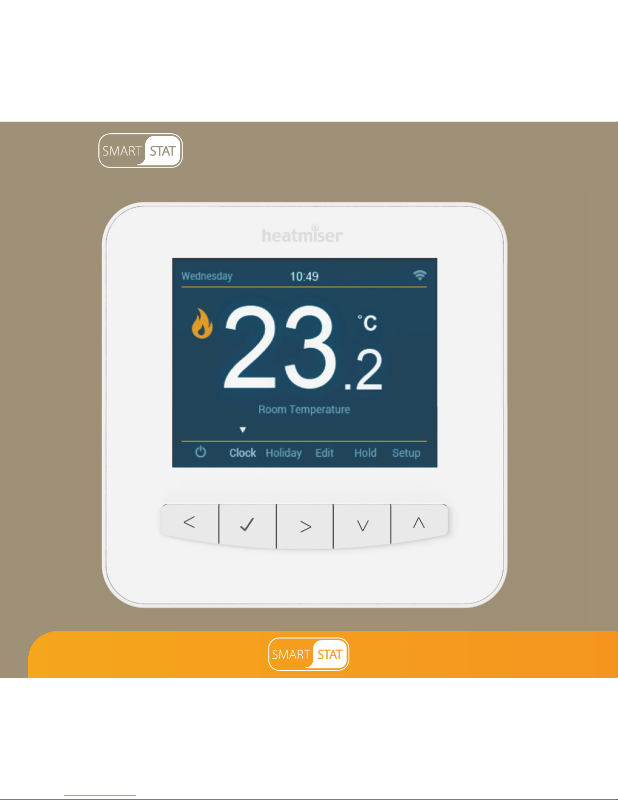
Model:
1
Available in : Sapphire Black and Glacier White
Page 2

2
Table of Contents
1
2
3-4
5-6
7-8
9
10
Product Image
Table of Contents
What is a Programmable
Room Thermostat?
Installation Procedure
Mode Select / Factory Reset
WiFi Setup
Pairing with SmartStat App
33-34
35
36
37
37
38-39
40
33-34
36
LCD Display
Setting the Switching Times
Timer Boost
Optional Features
Optional Features Table
Time Clock Mode Wiring Diagrams
Battery Replacement
Timer Boost
Mode 2 - Time Clock
LCD Display
Temperature Display
Setting the Time & Date
Setting the Comfort Levels
Setting the Temperature
Temperature Hold
3-4
What is a Programmable
32
Mode 1 - Thermostat 11
12-13
14
15
16-17
18
19
Locking/Unlocking the SmartStat
Standby/Away Mode
Power ON/OFF
Holiday Programming
Optional Features
Re-calibrating the Thermostat
Error Codes
Thermostat Mode Wiring Diagram
wer ON/OFF
37
40
Optional Features Table
Optional Features
20
21
22
23
24-27
28
28
29-31
Page 3

3
Section Header
What is a Programmable Room Thermostat?
A programmable room thermostat is both a programmer and a room thermostat.
A programmer allows you to set “On” and “Off” periods to suit your own lifestyle.
A room thermostat works by sensing the air temperature, switching on the heating
when the air temperature falls below the thermostat setting, and switching it off once
this set temperature has been reached.
So a programmable room thermostat lets you choose what times you want the heating
to be on, and what temperature it should reach while it is on. It will allow you to select
different temperatures in your home at different times of the day (and days of the week)
to meet your particular needs and preferences.
Setting a programmable room thermostat to a higher temperature will not make the
room heat up any faster. How quickly the room heats up depends on the design and
size of the heating system.
Similarly reducing the temperature setting does not affect how quickly the room cools
down. Setting a programmable room thermostat to a lower temperature will result in
the room being controlled at a lower temperature, and saves energy.
Page 4

Section Header
4
The way to set and use your programmable room thermostat is to find the lowest
temperature settings that you are comfortable with at the different times you have
chosen, and then leave it alone to do its job.
The best way to do this is to set the room thermostat to a low temperature – say 18°C
and then turn it up by 1°C each day until you are comfortable with the temperature.
You won’t have to adjust the thermostat further. Any adjustment above this setting
will waste energy and cost you more money.
You are able to temporarily adjust the heating program by overriding or using the
temperature hold feature. These features are explained further on pages 18 and 19
of this manual.
Programmable room thermostats need a free flow of air to sense the temperature,
so they must not be covered by curtains or blocked by furniture. Nearby electric
fires, televisions, wall or table lamps may also prevent the thermostat from working
properly.
Page 5
5
Section Header
Installation Procedure
This SmartStat is designed to be flush mounted and requires a back box of
35mm (minimum depth) to be sunk into the wall prior to installation.
Step 1
Using a small screwdriver, slightly loosen the screw from the bottom face of the
SmartStat. You can then carefully separate the front half from the back plate.
Step 2
Place the SmartStat front somewhere safe.
Terminate the SmartStat as shown in the diagrams on pages
29-31 of this booklet.
Note: For time clock wiring connections, terminate as shown on pages 38-39.
Step 3
Screw the SmartStat back plate securely into the back box.
Step 4
Clip the front of the SmartStat onto the back plate, securing it in place with the
retaining screw.
Do
Mount the SmartStat at eye level.
Read the instructions fully so you get the best from our product.
Don’t
Do not install near to a direct heat source as this will affect functionality.
Do not push hard on the LCD screen as this may cause irreparable damage.
Page 6

Section Header
6
1 2
3 4
Page 7

7
Section Header
Mode Select
This SmartStat can either be used as a thermostat or a time clock.
Thermostat mode is the default setting.
To change between thermostat & time clock modes, follow these steps.
• Use the Left / Right keys to scroll to Setup .....................................................
• Press and hold the Tick key for 5 seconds .................................................................
• Use the Up / Down keys to scroll between modes .......................................
• Press the Tick key to confirm selection ......................................................................
The SmartStat will reset all parameters and restart in the selected mode.
Note: The Mode Select function will reset all parameters that were entered during
the set-up andpairing operations. These processes must be repeated after the
restart has completed.
Page 8

Section Header
8
Thermostat mode Time Clock Mode
Mode Select Restart Screen
Page 9
9
Section Header
WiFi Setup
The SmartStat will then connect to the chosen WiFi network. During this process the WiFi
icon and “Connecting” will be displayed. If successful a Tick symbol will be displayed
next to the network name, the SmartStat will then return to the main display.
* Note: To join a closed/hidden WiFi network, within ‘WiFi Setup, use the up/down keys to scroll to
‘Other’. Here you can manually enter the SSID, security type and security key then select ‘Join.
To connect the SmartStat with the WiFi network follow these steps.
• Use the Left / Right keys to scroll to Setup and press Tick ..................
• Use the Down arrow key to scroll to WiFi Setup and press Tick ........
• Use the Up / Down keys to scroll to Scan Available Networks .................
• Press the Tick key ..............................................................................................................
• The SmartStat will scan and list all available WiFi networks.
• Use the Up / Down keys to select a network ...................................................
• Press the Tick key .............................................................................................................
• Using the Arrow keys to navigate and the Tick key to select,
enter the network key using the keypad ....................................
• Once the network key has been entered, use the arrow keys
and navigate to ‘Join' .......................................................................................................
• Press the Tick key to confirm ........................................................................................
Page 10
Section Header
10
Pairing with SmartStat App
Download the FREE Heatmiser SmartStat App from the Apple App Store,
Google Play Store or Amazon App Store.
• Open the SmartStat App, create your account & login
• Press ‘Add Location’
• Enter a name for your location, for example ‘Home’
• Select the correct time zone for your location, for example ‘GMT’ then press
Submit
• Once the location has been created, now add your SmartStats to the location.
• Select ‘Add Zone’ and enter the first zone title, for example ‘Living Room’, press
‘Add Zone'
• On the SmartStat, use the Left / Right keys to scroll to setup
and press Tick .......................................................................................................
• ‘Pairing with App’ will be highlighted in the menu, press the Tick
key to start pairing .............................................................................................................
• Both the App & the SmartStat will display a green tick symbol
once pairing is successful
Note: To pair more SmartStats to the location, select ‘Add Zone’ within the ‘Manage Zones’
section and repeat the steps above.
Page 11
11
Section Header
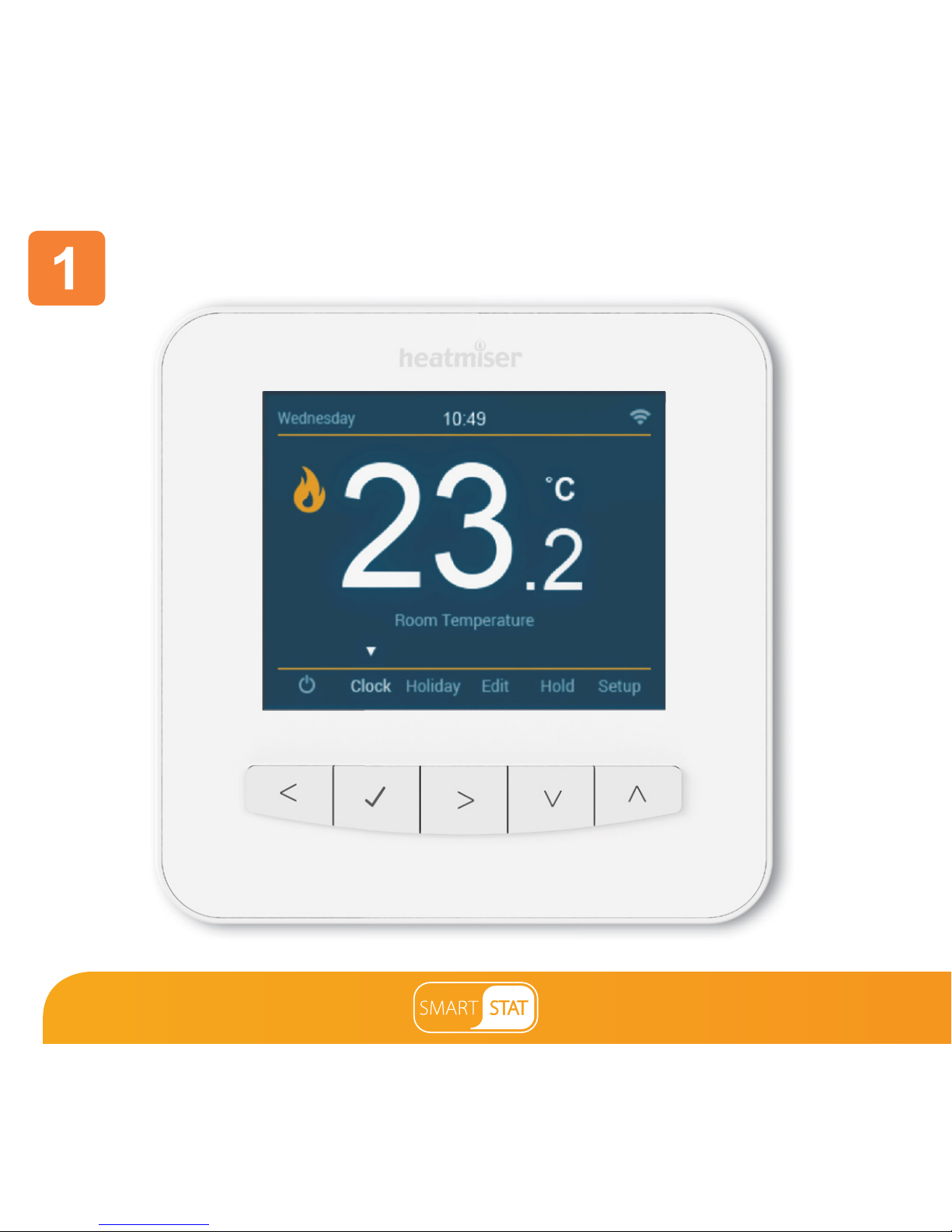
Mode 1 - Thermostat
Page 12
Section Header
12
1 2
5
3
11
10
9
12
4
6
7
8
Page 13

13
Section Header
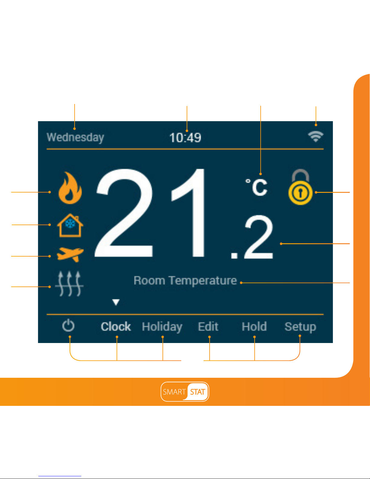
1. Day Indicator - Displays the day of the week.
2. Clock - Time displayed in 24 hour format.
3. Temperature Format – Degrees Celsius or Fahrenheit.
4. WiFi Indicator - Displayed when connected to a WiFi network.
5. Flame Symbol – Displayed when the thermostat is calling for heat and
flashes when optimum start is active.
6. Frost Protection – Displayed when Away/Standby modes are active.
7. Holiday – Displayed when the thermostat is in holiday mode.
8. Floor Limit Symbol – Displayed when the floor probe has reached the floor
temperature limit configured in the setup menu.
9. Main Menu – Highlighted display indicates selected option.
10. Floor/Room Temp – Indicates the current sensor mode.
11. Temperature – Displays the current sensor temperature.
12. Keypad Lock Indicator – Displayed when the keypad is locked.
Main Display
Page 14
Section Header
14
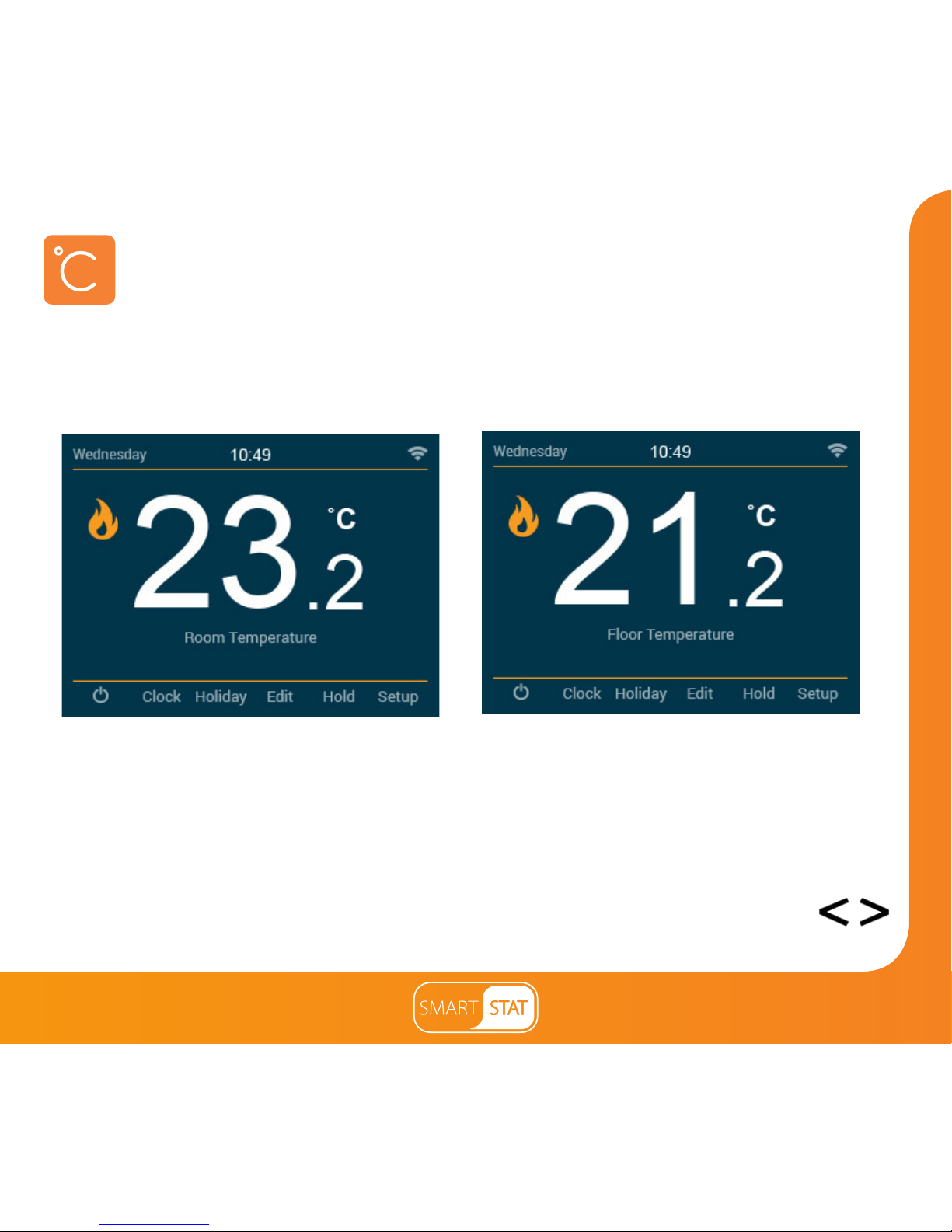
This SmartStat can be configured for different sensor options such as built in air sensor,
floor sensor or both. The display will clearly indicate which sensor is being used by
showing either “Room Temperature” or “Floor Temperature” under the actual value.
When the SmartStat is set to use both the air & the floor sensor, the room temperature
will be displayed by default.
To view the current floor temperature, press and hold the Left and Right arrow
keys for 5 seconds, the floor temperature will then be displayed. .............................
Temperature Display
Room Temperature Floor Temperature
Page 15
15
Section Header
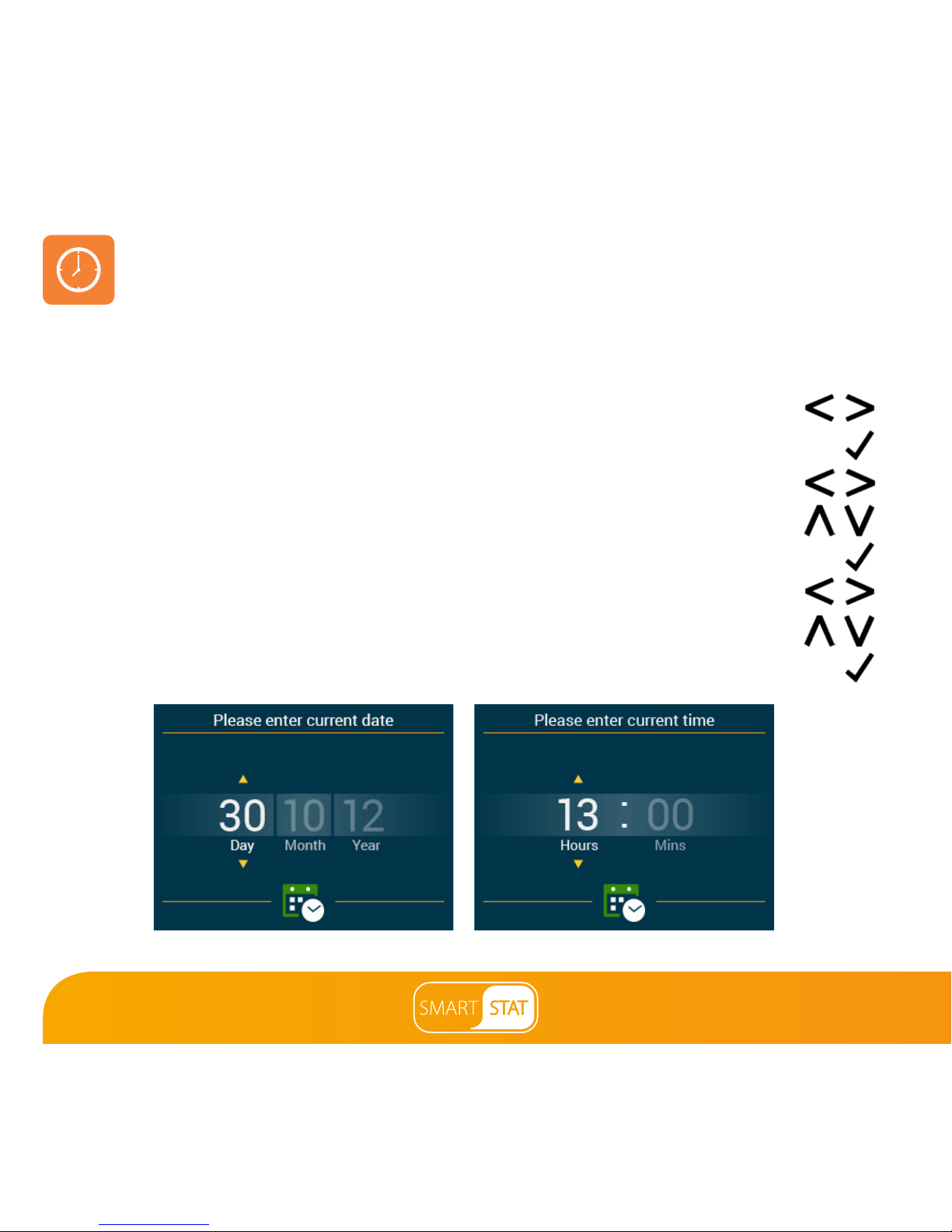
Setting the Time and Date
To set the clock, follow these steps.
• Use the Left / Right keys to scroll to Clock .........................................................
• Press Tick to confirm selection .........................................................................................
• Use the Left / Right keys to scroll between Day/Month/Year values ........
• Use the Up / Down keys to set the Day/Month/Year values ..........................
• Press Tick to confirm selections and progress to Time ............................................
• Use the Left / Right keys to scroll between hours and minutes ..................
• Use the Up / Down keys to set the hours/minutes values .............................
• Press Tick to confirm selection and return to the main display ...........................
Setting the date Setting the time
Note: When the SmartStat is paired with the app, the time & date settings are
automatically synchronised according to the location’s time zone setting.
Page 16
Section Header
16
Comfort Levels Explained
The SmartStat offers three program mode options; Weekday/Weekend programming,
7 Day programming and 24 Hour programming.
You also have the option to use the SmartStat in Non-Programmable mode.
The SmartStat is supplied with comfort levels already programmed, but these can be
changed easily. The default times and temperature settings are;
08:00 - 21°C (Wake) 09:30 - 16°C (Leave) 16:30 - 22°C (Return) 23:00 - 17°C (Sleep)
For Weekday/Weekend programming, the four comfort levels are the same for Mon-Fri, but can
be different for Sat-Sun. For 7 Day programming each day of the week can have four different
comfort levels. In 24 Hour mode all days are programmed with the same comfort levels.
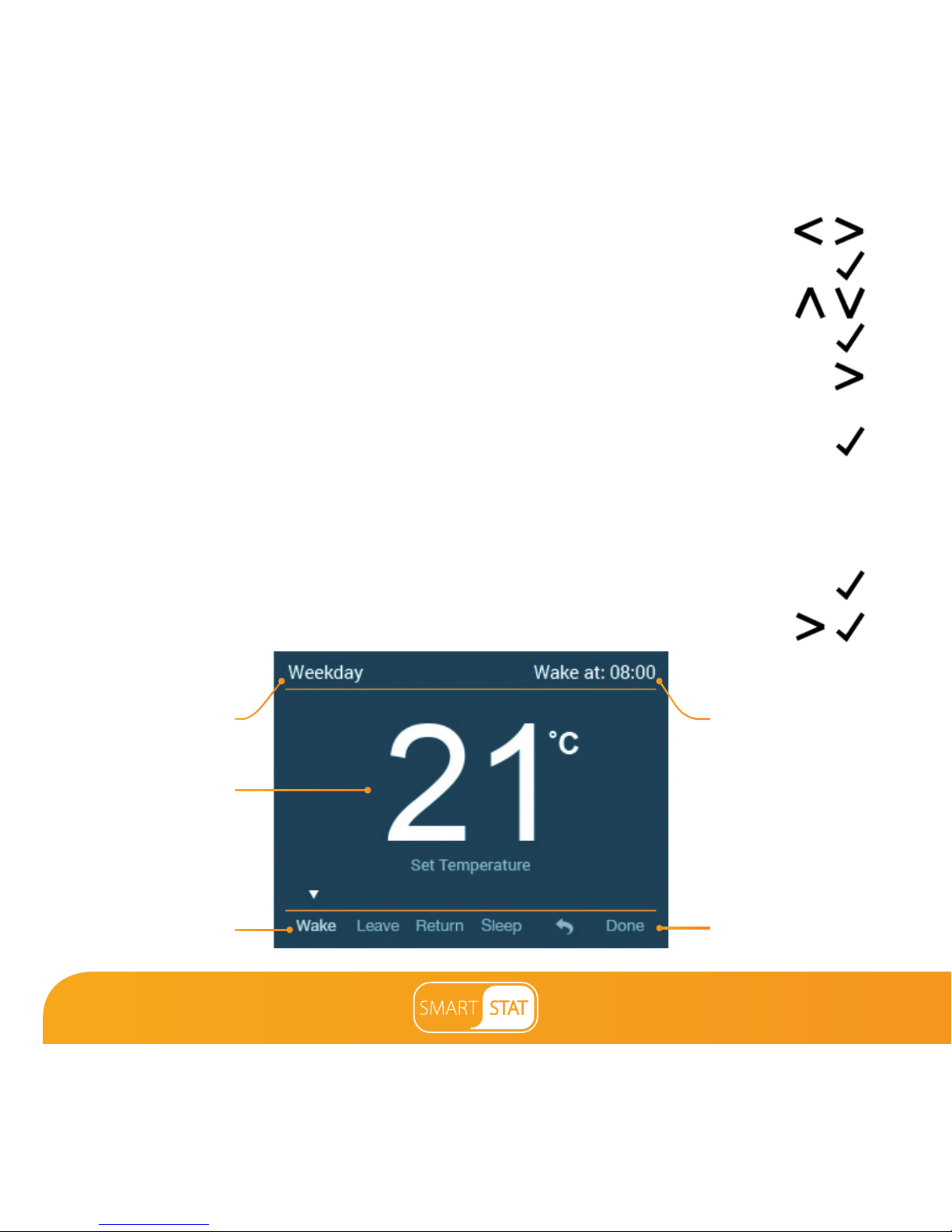
• To program the comfort levels, use the Left / Right keys to scroll to Edit .........................
• Press Tick to confirm selection ......................................................................................................................
• Use the Up / Down keys to select day / period of week ...........................................................
• Press Tick to confirm selection ......................................................................................................................
• Wake will now be highlighted and the current time and temperature settings shown.
• Press Tick to alter Wake settings ...................................................................................................................
• Use the Up / Down keys to set the time ....................................................................................
Page 17
17
Section Header
• Use the Left / Right keys to scroll between hours and minutes ...........
• Press Tick to confirm .............................................................................................................
• Use the Up / Down keys to set the temperature .........................................
• Press Tick to confirm the settings ....................................................................................
• Press the Right arrow key ............................................................................................
• Leave will now be highlighted and the current settings will be displayed.
• Press Tick to alter the Leave settings ..............................................................................
• Repeat these steps to set all comfort levels.
• To blank or set a comfort level period to unused, first select the comfort level
then press and hold the tick key for 5 seconds. 'Level unused' will appear in
the corner of the display ......................................................................................................
• When complete use the Right key to scroll to Done and press Tick .....
Comfort Level
Program Mode
Set Temperature
Set Time
Done
Page 18
Section Header
18
Temperature Control
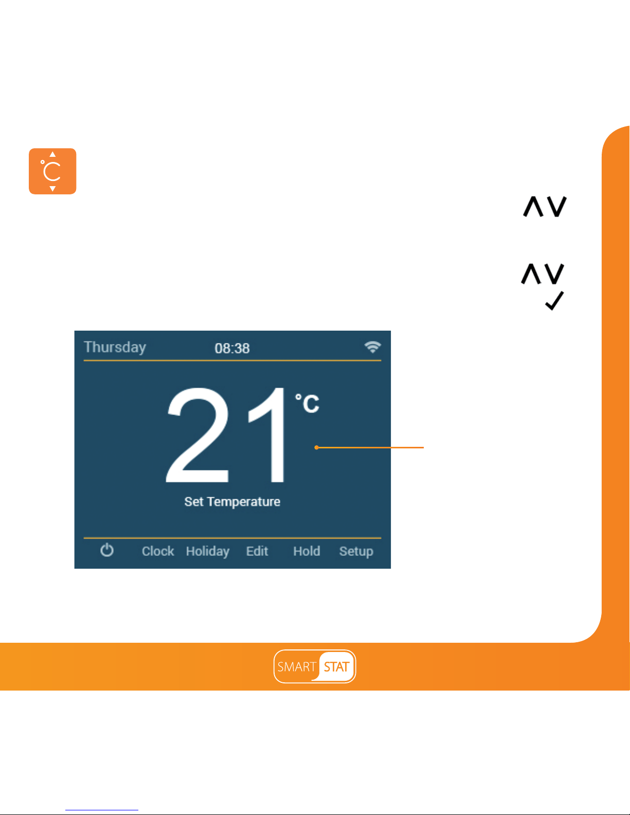
The Up / Down keys allow you to adjust the current set temperature ............
When you press either of these keys, you will see the Set Temperature and
the desired temperature value.
Use the Up / Down keys to adjust the set value .......................................................
Press Tick to confirm settings ..................................................................................................
Set Temperature
Note: This new temperature is maintained only until the next programmed comfort level.
At this time, the thermostat will revert back to the programmed levels.
Page 19
19
Section Header
Temperature Hold
The temperature hold function allows you to manually override the current operating
program and set a different temperature for a desired period.
• Use the Left / Right keys to scroll to Hold and press Tick .......................
• Use the Up / Down keys to set the desired Hold time ......................................
• Use the Left / Right keys to scroll between hours and minutes .....................
• Press Tick to confirm selection .........................................................................................
• Use the Up / Down keys to set the desired Hold temperature ......................
• Press Tick to confirm selection .........................................................................................
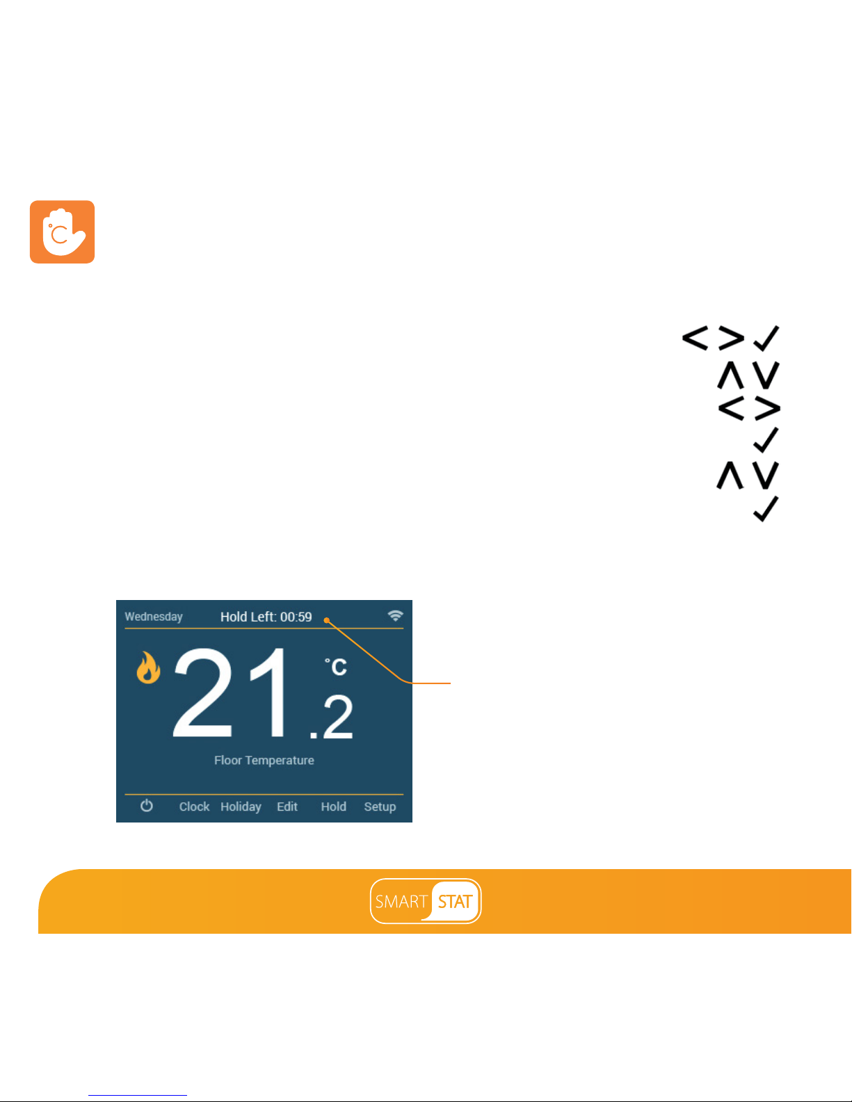
You will see the HOLD LEFT indication is displayed on screen.
The time will countdown the set duration and then revert to the normal program.
To cancel a temperature Hold, repeat these steps but reduce the Hold time to 00:00 hrs
HOLD LEFT Indicator and
hold time remaining
Page 20
Section Header
20
Locking the SmartStat
The SmartStat has a keypad lock facility. To activate the lock follow these steps.
• Use the Left / Right keys to scroll to Hold & press Tick for 5 seconds ...
• The display will show 0000 and you will need to enter a four digit pin number.
• Use the Up / Down keys to enter values .........................................................
• Use the Left / Right keys to move between digits ......................................
• Press Tick to confirm .......................................................................................................................
The display will return to the main screen and display the keypad lock indicator ......
To enable keylock in time clock mode, select Boost, press & hold tick for 5 seconds.
Note: The keypad lock indicator is only displayed when the lock is active.
Unlocking the SmartStat
To unlock the SmartStat press Tick once. The display will show **** and you will need to
enter the four digit pin number you set previously.
• Use the Up / Down keys to enter values ...........................................................
• Use the Left / Right keys to move between digits .......................................
• Press Tick to confirm ..............................................................................................................
The display will unlock and return to the main screen.
Page 21
21
Section Header
Frost
Protection
Symbol
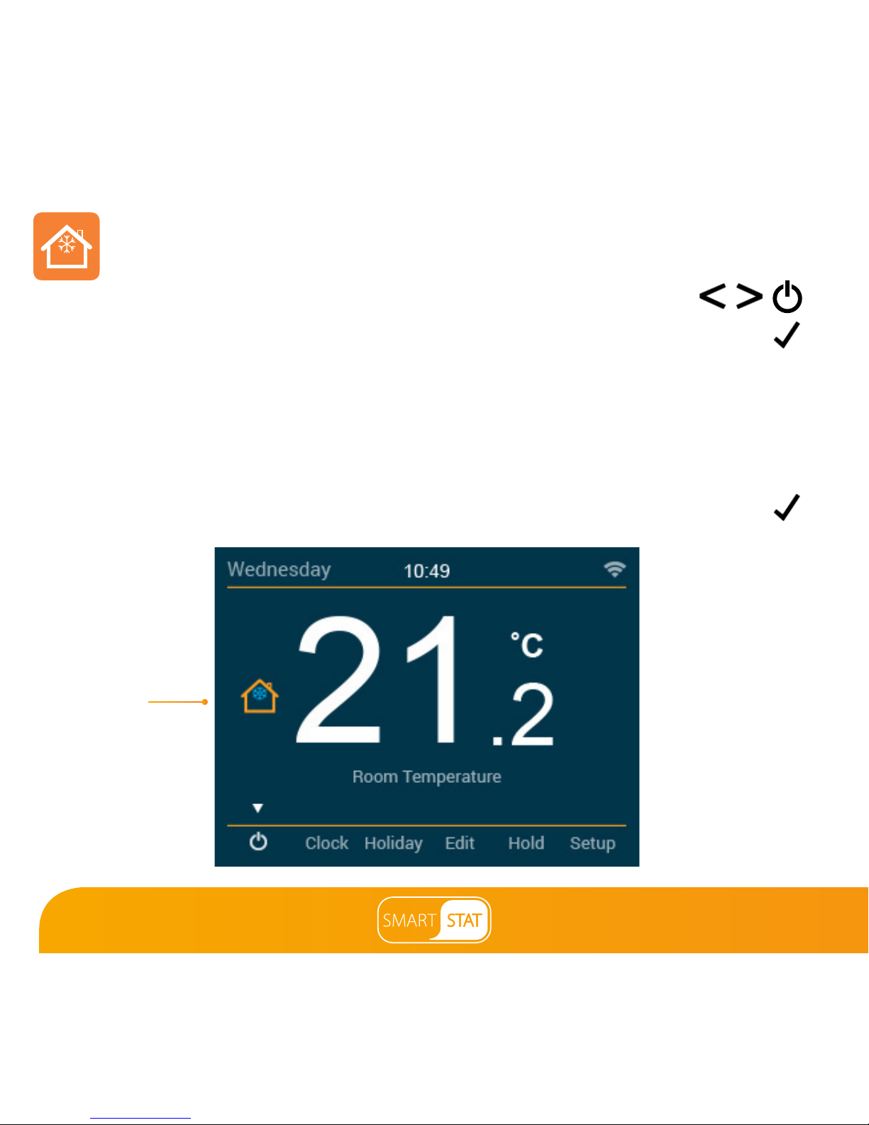
Standby/Away Mode
Use the Left / Right keys to scroll to the Power Icon .............................................
The Frost Protection Symbol will toggle ON/OFF each time Tick is pressed ................
In this mode, the SmartStat will only turn the heating ON should the room temperature
drop below the set Away Temperature. This is configured in the setup menu.
If the heating is turned ON whilst in Standby/Away Mode, the Flame symbol
will be displayed. To cancel the Standby/Away Mode, navigate to the Power
button and press Tick ........................................................................................................................
‘Note: Away & standby
modes both mean the
SmartStat is maintaining
a lower temperature to
give frost protection.
Away is global meaning
all zones on the system,
Standby is used for
individual zones.
Page 22
Section Header
22
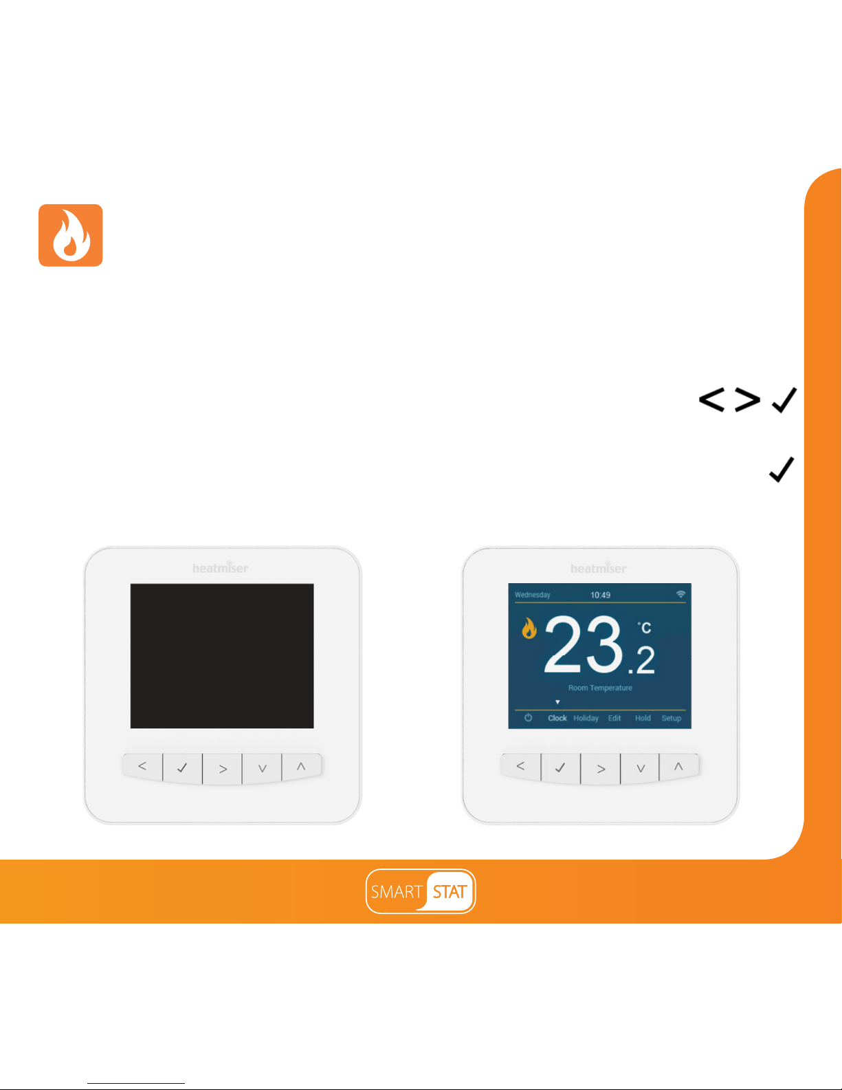
Power On/Off
The heating is indicated ON when the Flame Icon is displayed.
When the Flame Icon is absent, there is no requirement for heating to achieve the set
temperature but the SmartStat remains active.
To turn the SmartStat off completely, scroll to the Power Icon and hold
the Tick key for approximately 4 seconds until the display goes blank ..................
The display and heating output will be turned OFF.
To turn the SmartStat back ON, press the Tick key once .............................................................
SmartStat completely OFF SmartStat powered ON
Page 23
23
Section Header
Holiday
In time clock mode; the timed output will be turned off during the holiday period,
then return to the programmed settings once the holiday period finishes.
In thermostat mode; the holiday function reduces the set temperature in your home
to the Away mode temperature setting that is configured in the setup menu.
The SmartStat will maintain this temperature for the duration of the holiday and will
then automatically return to the program mode on your return.
• Use the Left / Right keys to scroll to Holiday and press Tick ................
• Using the Up / Down keys enter the number of days holiday .....................
• Press Tick to confirm settings ...........................................................................................
To cancel the holiday, repeat these steps but reduce the Holiday duration to 00 days.
Note: A holiday period does not start until 00:00 the next day. For example, if you set a
holiday period on Friday for 2 days, Saturday will be counted as the first day and the
thermostat will revert back to the programmed schedule at 00:00 on Monday.
Page 24

Section Header
24
Optional Features Explained
THE FOLLOWING SETTINGS ARE OPTIONAL AND IN MOST CASES
NEED NOT BE ADJUSTED.
Pairing With the App: This function is used to pair the SmartStat to the SmartStat App.
WiFi Set-Up: This function is used to connect the SmartStat with the WiFi network.
Switching Differential: This function allows you to increase the switching differential of
the thermostat. The default is 0.5°C which means that with a set temperature of 20°C, the
thermostat will switch the heating on at 19.5°C and off at 20.0°C. With a 1°C differential,
the heating will switch on at 19.0°C and off at 20.0°C.
Away Temperature: This is the temperature maintained when the thermostat is in Away
Mode. The range is 7 - 17°C. The default is 12°C and is suitable for most applications.
Output Delay: To prevent rapid switching, an output delay can be entered.
This can be set from 00 - 15 minutes. The default is 00 which means there is no delay.
Temperature Up/Down Limit: This function allows you to limit the use of the up and
down temperature arrow keys. This limit is also applicable when the thermostat is locked
and so allows you to give others limited control over the heating system.
Sensor Selection: On this SmartStat, you can select which sensor should be used. You can
select between air temperature only, floor temperature, or both. When you enable both
sensors, the floor sensor is used as a floor limiting sensor and is designed to prevent the
floor from overheating.
Page 25

25
Section Header
Floor Temp Limit: This function is available when the floor sensor is enabled. You can
set a floor limiting temperature between 20-45°C (27°C is the default setting).
Note: Air Sensor only MUST NOT be used to control electric underfloor heating.
Floor Sensor or Both should be used.
Optimum Start: Optimum start will delay the start up of the heating system to the
latest possible moment to avoid unnecessary heating and ensure the building is
warm at the programmed time. The SmartStat uses the rate of change information
to calculate how long the heating needs to raise the building temperature 1°C (with
a rate of change of 20, the SmartStat has calculated the heating needs 20 minutes to
raise the building temperature 1°C) and starts the heating accordingly.
Rate of Change: Number of minutes for 1°C temperature rise.
Program Mode: The SmartStat offers three programming modes and the option of
configuring it to work as a non-programmable thermostat.
Weekday/ Weekend - allows you to program 4 comfort levels for the weekday
and 4 different comfort levels for the weekend.
7 Day Program Mode - Each day has 4 comfort levels that can be programmed
independently.
24 Hour Mode - All days are programmed the same and repeat continuously.
Temperature Format: This function is used to select between °C and °F.
Ambient Light Dimming: When this function is enabled, the light sensor will detect
when to dim the backlight when the ambient light levels drop. If you turn the room
lights off, the backlight will dim so the SmartStat does not light up the room.
Page 26
Section Header
26
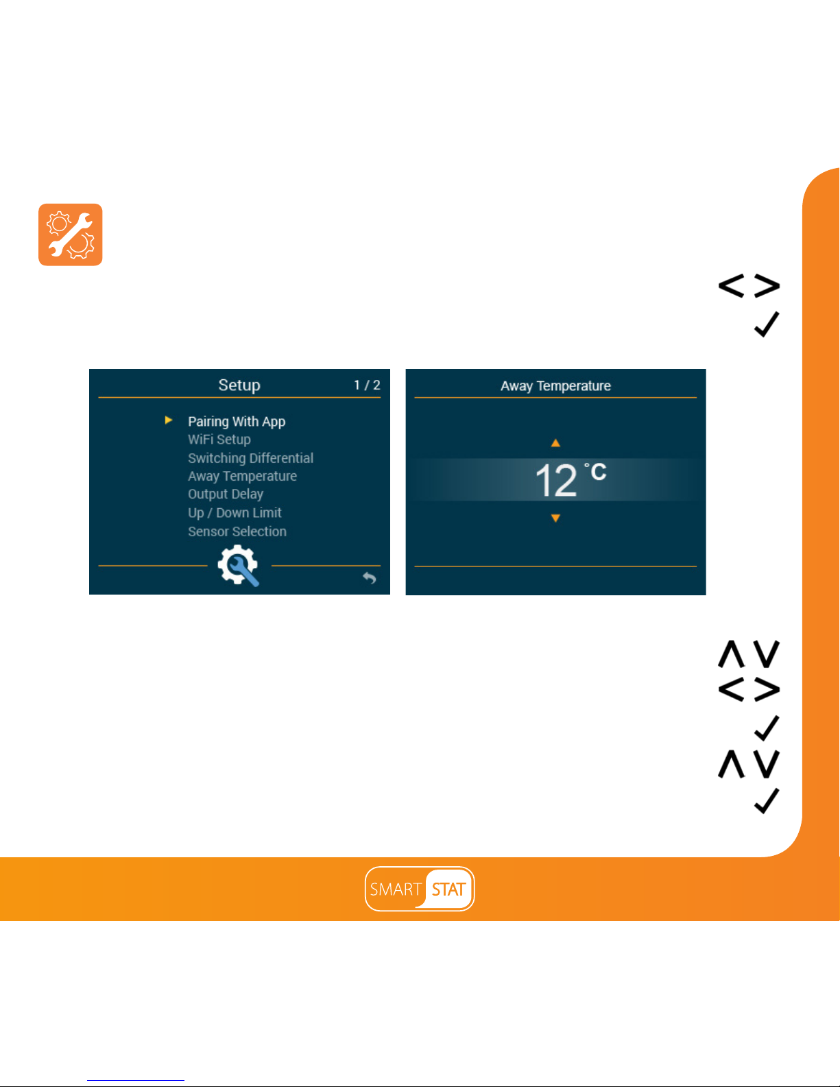
Adjusting the Optional Settings
• Use the Left / Right keys to select Setup ......................................................
• Press Tick to confirm selection ...........................................................................................
• Use the Up / Down keys to scroll through features ..................................
• Use the Left / Right keys to change page .....................................................
• Press Tick to edit a feature ....................................................................................................
• Use the Up / Down keys to adjust the feature setting ..............................
• Press Tick to confirm settings and return to the feature menu ................................
Features Menu Feature Editing
Page 27
27
Section Header
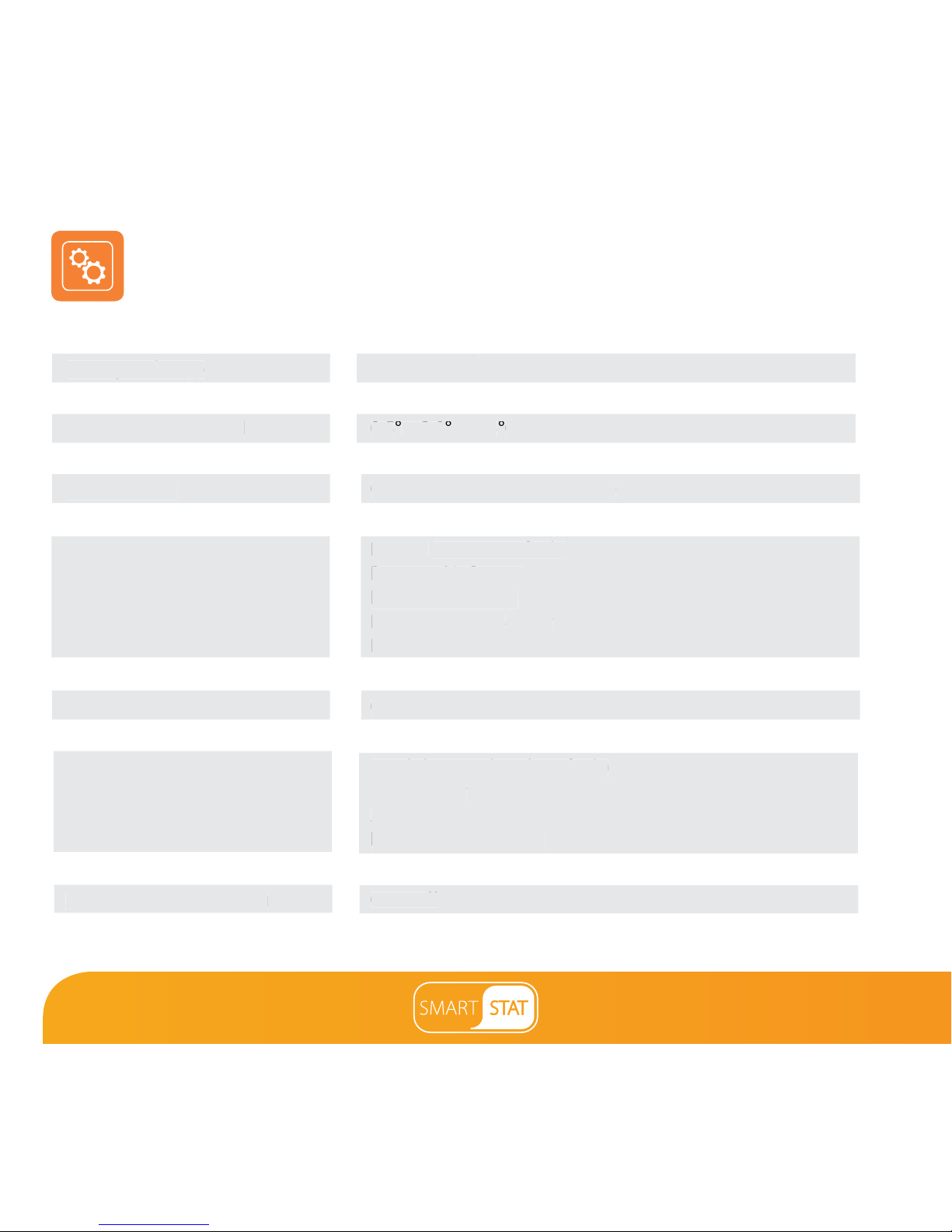
Optional Settings - Feature Table
Pairing with App
WiFi Setup
Switching Differential
Away Temperature
Output Delay
Up/Down Temperature Limit
Sensor Selection
Floor Temperature Limit
Optimum Start
Rate of Change
Program Mode
Temperature Format
Ambient Light Dimming
Output Delay
Sensor Selection
Switching Differential
FEATURE
Used to connect to the WiFi network
0.5° - 3.0°C (0.5°C = Default)
7° - 17°C (12°C = Default)
00 - 15 Minutes (00 = Default)
00° - 10°C (00 = Default)
Built in Sensor (Default)
Remote Air Sensor
Floor Sensor Only
Built in & Floor Sensor
Remote Air & Floor Sensor
20°C - 45°C (27°C = Default)
00-05 hours (00 = Disabled as default)
Minutes to raise temperature by 1°C
Weekday/Weekend (Default)
7 Day Programming
24 Hour Mode
Non - Programmable
00 = °C, 01 = °F (00 = Default)
On / Off
00 - 15 Minutes (00 = Default)
Sensor (Default)
ensor
0.5
- 3.0
C (0.5
C = Default)
SETTING
Optimum Start
00-05 hours (00 = Disabled as default)
Weekday/Weekend (Default)
amming
24 Hour Mode
Ambient Light Dimming
On / Off
Used to add pair with the SmartStat App
Page 28
Section Header
28
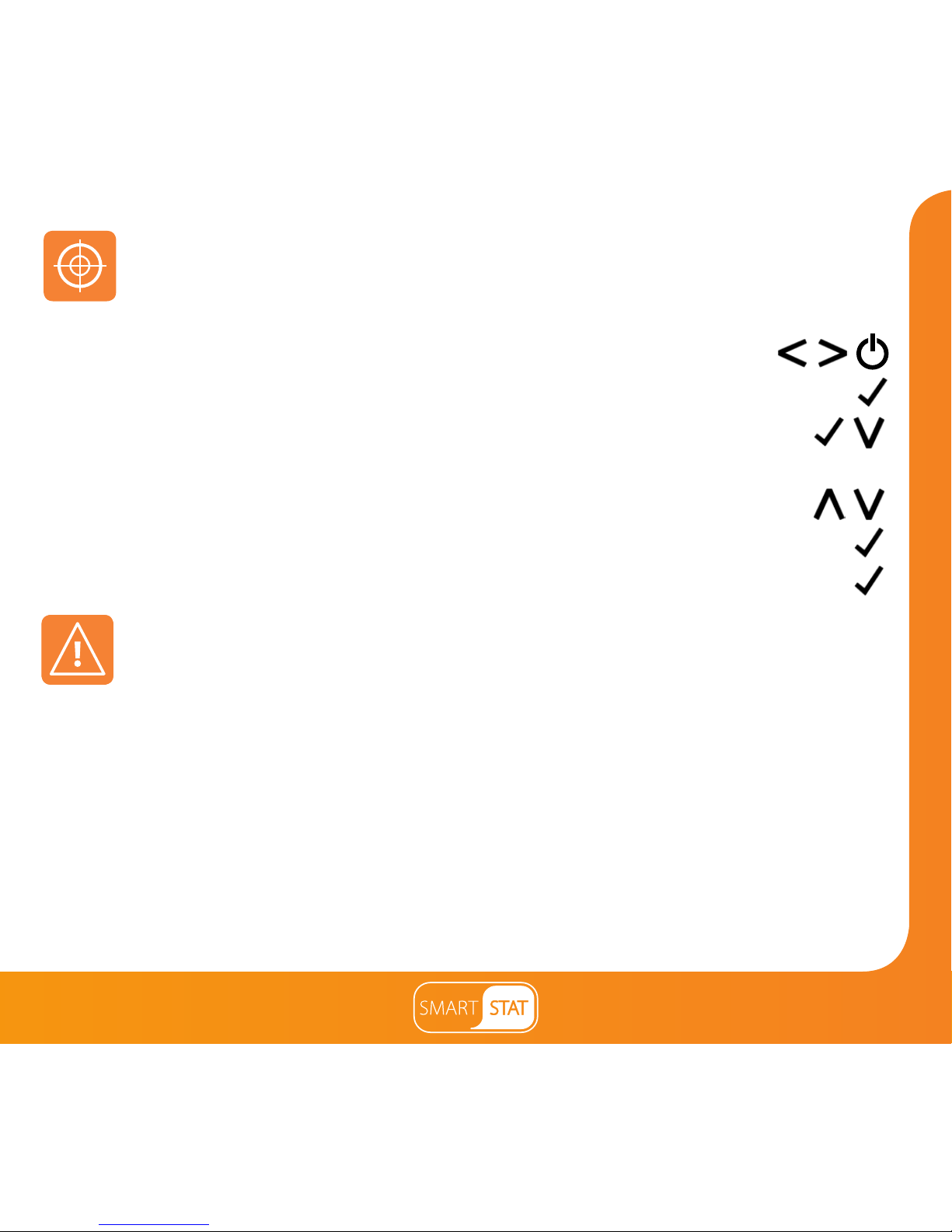
Re-calibrating the SmartStat
If you need to re-calibrate the SmartStat, follow these steps.
• Use the Left / Right keys to scroll to the Power Icon .................................
• Press and hold Tick to turn the display OFF ..................................................................
• Press and hold the Tick and Down keys together for 4 seconds ..................
• The current temperature will appear on the display.
• Use the Up / Down keys to configure the new temperature value .............
• Press the Tick key to confirm the change and the display will go blank ............
• Press the Tick key once to turn the thermostat ON .....................................................
Error Codes
E0 = The internal sensor has developed a fault.
E1 = The remote FLOOR probe has not been connected.
The remote FLOOR probe has not been wired correctly.
The remote FLOOR probe is faulty.
E2 = The remote AIR probe has not been connected.
The remote AIR probe has not been wired correctly.
The remote AIR probe is faulty.
The SmartStat will display an error code if there is a fault with the temperature sensor,
these error codes are explained below.
Page 29
29
Section Header
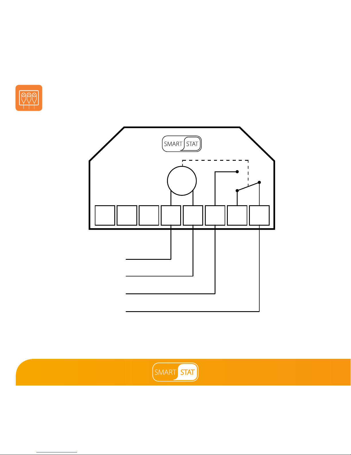
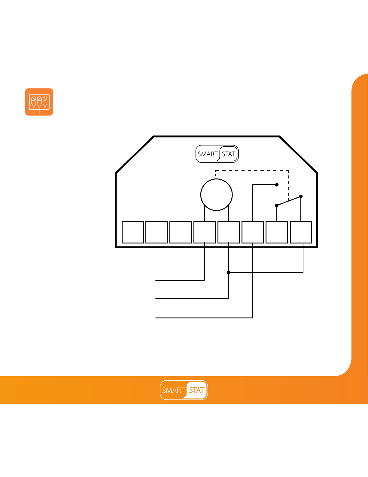
Wiring Diagram – Volt Free Output
This product must only be installed by a qualified electrician
and comply with local installation regulations.
NCNO
COM
Volt Free
Output
Live
N
TIMER
Neutral
230V Supply In
L
RT2 RT1-
Page 30
Section Header
30
Wiring Diagram – Switch Live Output
This product must only be installed by a qualified electrician
and comply with local installation regulations.
Switch Live
Live
Neutral
230V Supply In
TIMER
NCNO
COM
N
L
RT2 RT1-
Page 31
31
Section Header
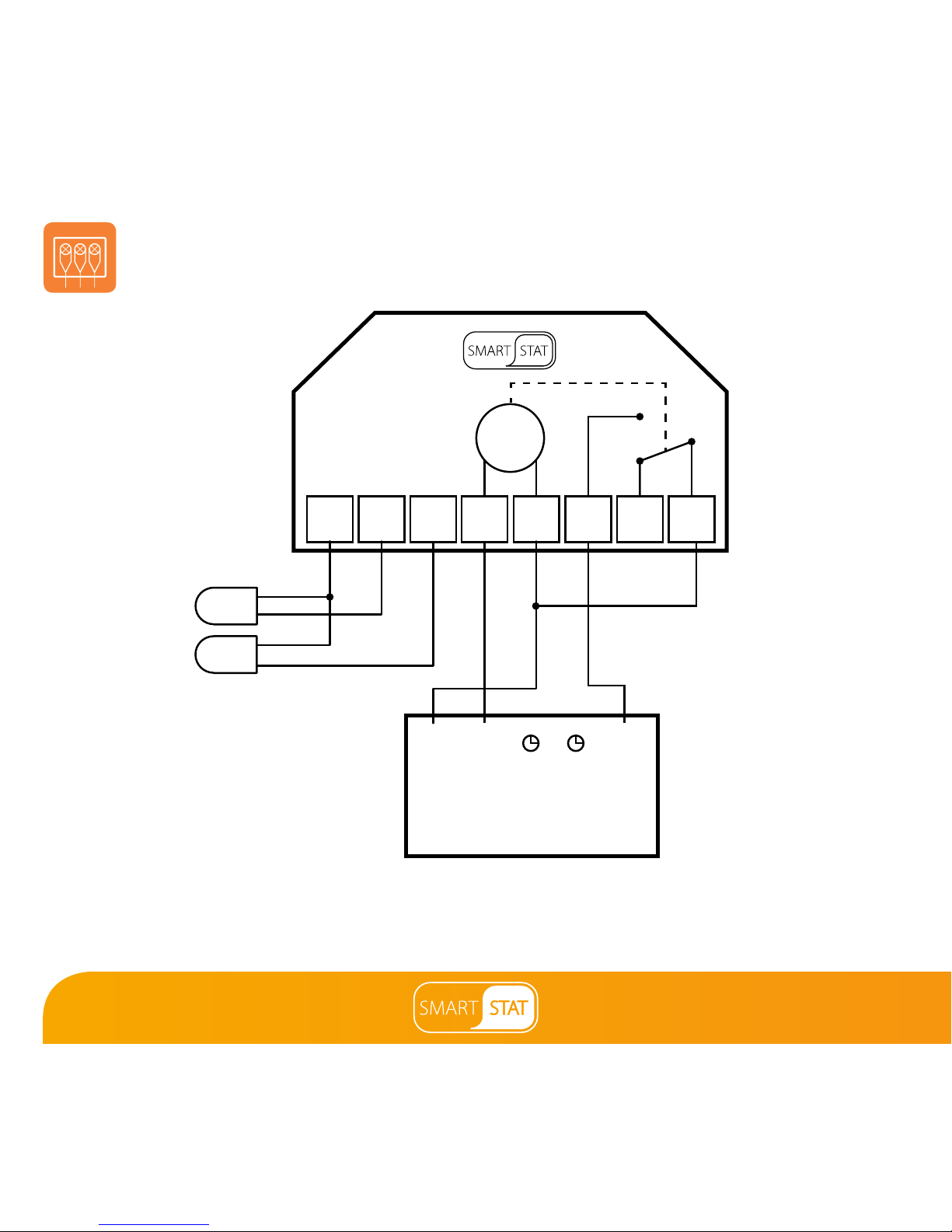
Wiring Diagram - Switch Live to UH3
This product must only be installed by a qualified electrician
and comply with local installation regulations.
NCNO
RT1RT2 L
COM
N-
L N SL
UH3
Remote
Air Probe
Floor Probe
TIMER
Page 32
Section Header
32
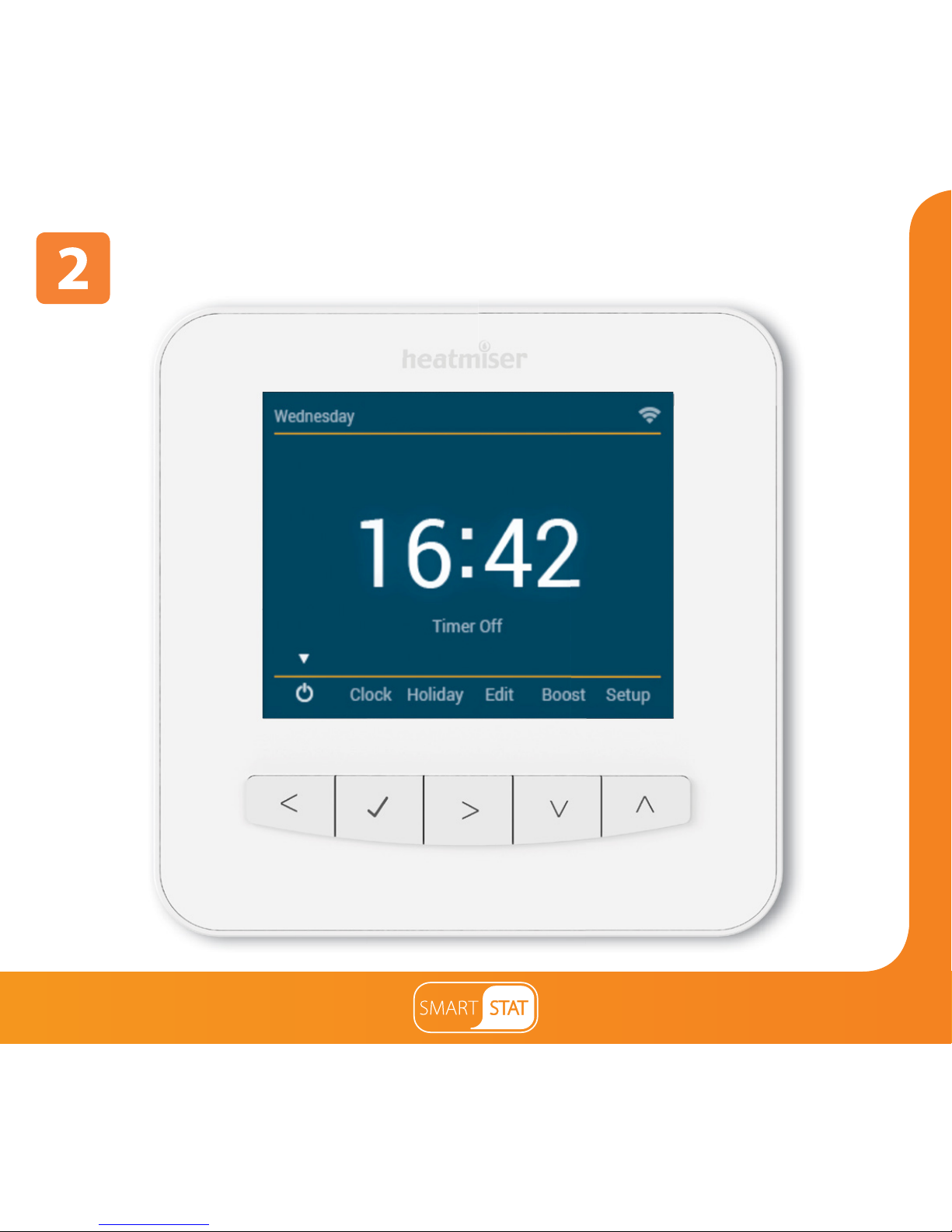
Mode 2 - Time Clock
Page 33
33
Section Header
1
3
5
8
7
6
4
2
Page 34

Section Header
34
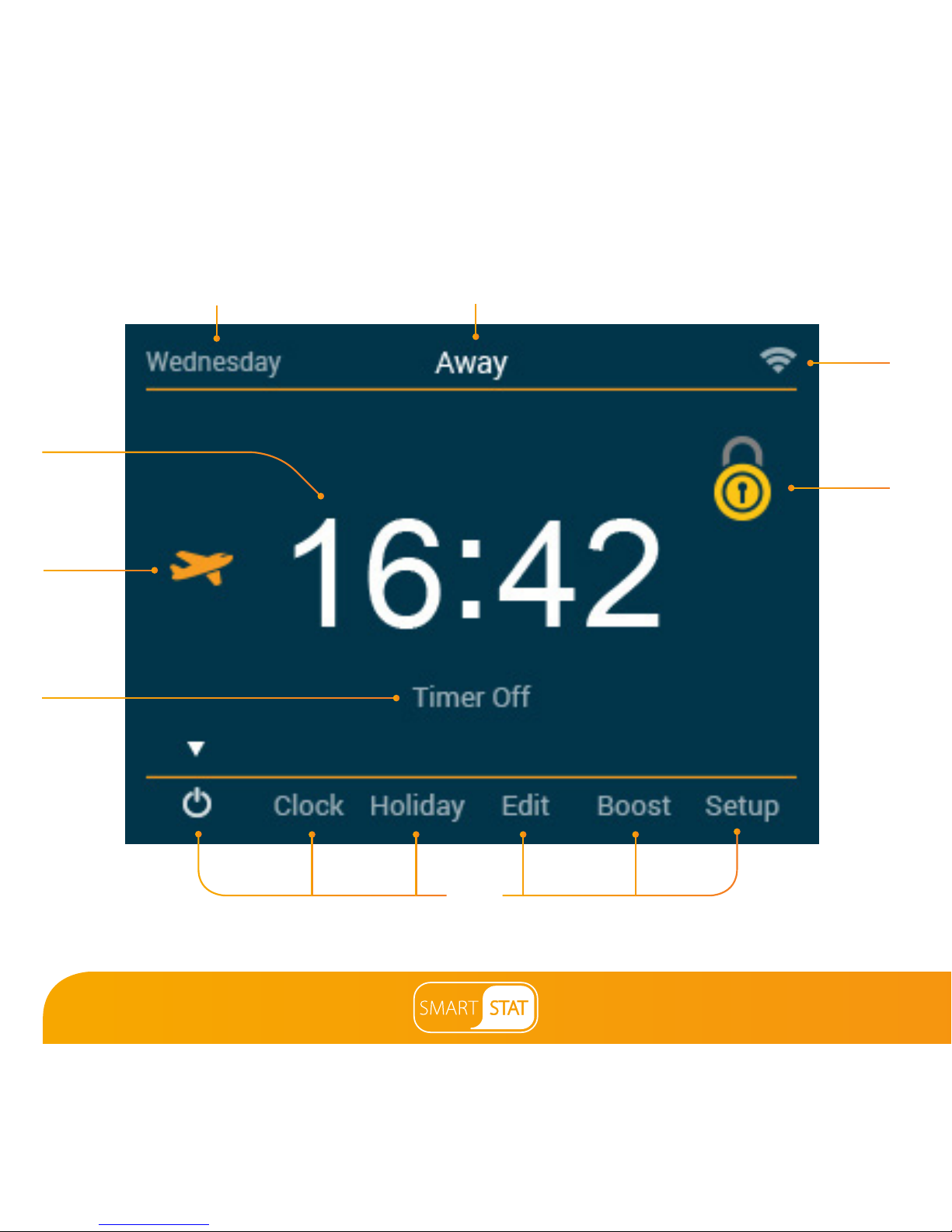
1. Day Indicator - Displays the day of the week.
2. Away – Displayed when Away mode is active.
3. Clock - Time displayed in 24 hour format.
4. Holiday – Displayed when the time clock is in Holiday mode.
5. Timer Status – Displays the current status of the timed output.
6. Main Menu – Highlighted display indicates selected option.
7. Keypad Lock Indicator – Displayed when the keypad is locked.
8. WiFi Indicator - Displayed when connected to a WiFi network.
LCD Display
Page 35
35
Section Header
To program the switching times, follow these steps
• Use the Left / Right keys to scroll to Edit ...................................................................
• Press Tick to confirm selection ...............................................................................................
• Use the Up/Down keys to select the day/period to program .............................
• Press Tick to confirm selection ..............................................................................................
• 1 will now be highlighted and the ON / OFF times will be displayed.
• Press Tick to alter period 1 .......................................................................................................
• To set the ON time, use the Up/Down keys to set the hours,
press the Right arrow key & use Up/Down to set the minutes ....
• Press Tick to confirm ..................................................................................................................
• To set the OFF time, use the Up/Down keys to set the hours,
press the Right arrow key & use Up/Down to set the minutes ....
• Press Tick to confirm the settings .........................................................................................
• Press the Right arrow key ........................................................................................................
• 2 will now be highlighted and the current settings will be displayed.
• Press Tick to alter period 2 settings .....................................................................................
• Repeat these steps to set all periods.
• To blank or set a switching level period to unused, first select the switching level
then press and hold the tick key for 5 seconds.
• When all switching times have been programmed use the Right arrow key
to scroll to Done and press Tick .....................................................................................
Setting the Switching Times
Page 36
Section Header
36
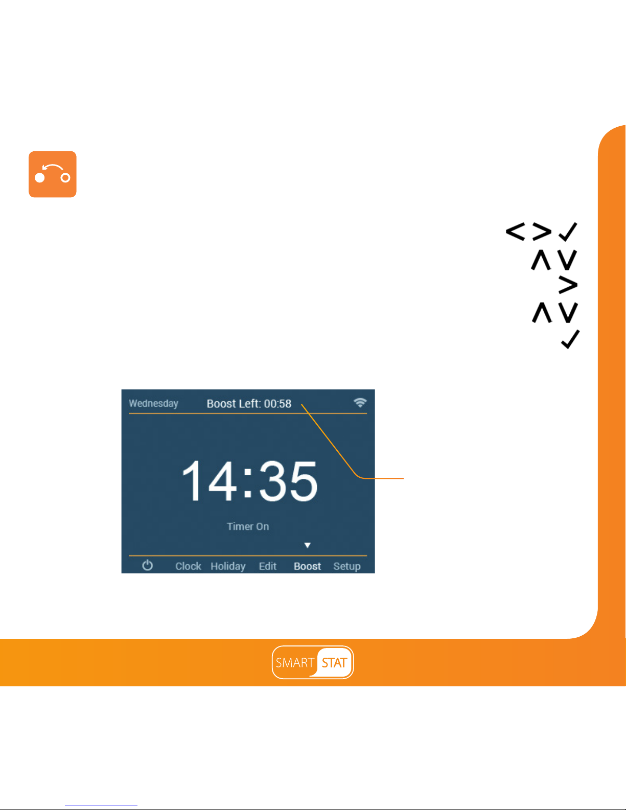
To boost the timed output ON follow these steps.
• Use the Left / Right keys to scroll to Boost and press Tick .....................
• Use the Up / Down keys to set the hours ...............................................................
• Press the Right key to select minutes ..............................................................................
• Use the Up / Down keys to set the minutes ..........................................................
• Press Tick to confirm settings and return to main display ......................................
Boost Left and the remaining time will now be displayed.
Timer Boost
Boost Remaining
Note: In time clock mode pressing the Up / Down keys from the home screen will navigate
directly to the boost screen.
Page 37
37
Section Header
Optional Settings - Feature Table
WiFi Setup
Program Mode
Ambient Light Dimming
FEATURE
Used to connect to the WiFi network
Weekday/Weekend Programming (Default)
7 Day Programming
24 Hour Mode
ON / OFF
SETTING
Used to pair to the SmartStat App
Optional Features Explained
Pairing With the App: This function is used to pair the SmartStat to the SmartStat App.
WiFi Set-Up: This function is used to connect the SmartStat with the WiFi network.
Program Mode: The time clock offers three programming modes:
Weekday/Weekend (5/2), 7 Day Programming or 24 Hour.
Weekday/ Weekend - allows you to program 4 comfort levels for the weekday and
4 different comfort levels for the weekend.
7 Day Program Mode - Each day has 4 comfort levels that can be programmed
independently.
24 Hour Mode - All days are programmed the same and repeat continuously.
Ambient Light Dimming: When this function is enabled, the light sensor will detect
when to dim the backlight when the ambient light levels drop. If you turn the room
lights off, the backlight will dim so the SmartStat does not light up the room.
Pairing with the App
Weekday/Weekend Programming (Default)
24 Hour Mode
Page 38
Section Header
38
(Mid Position Valve)
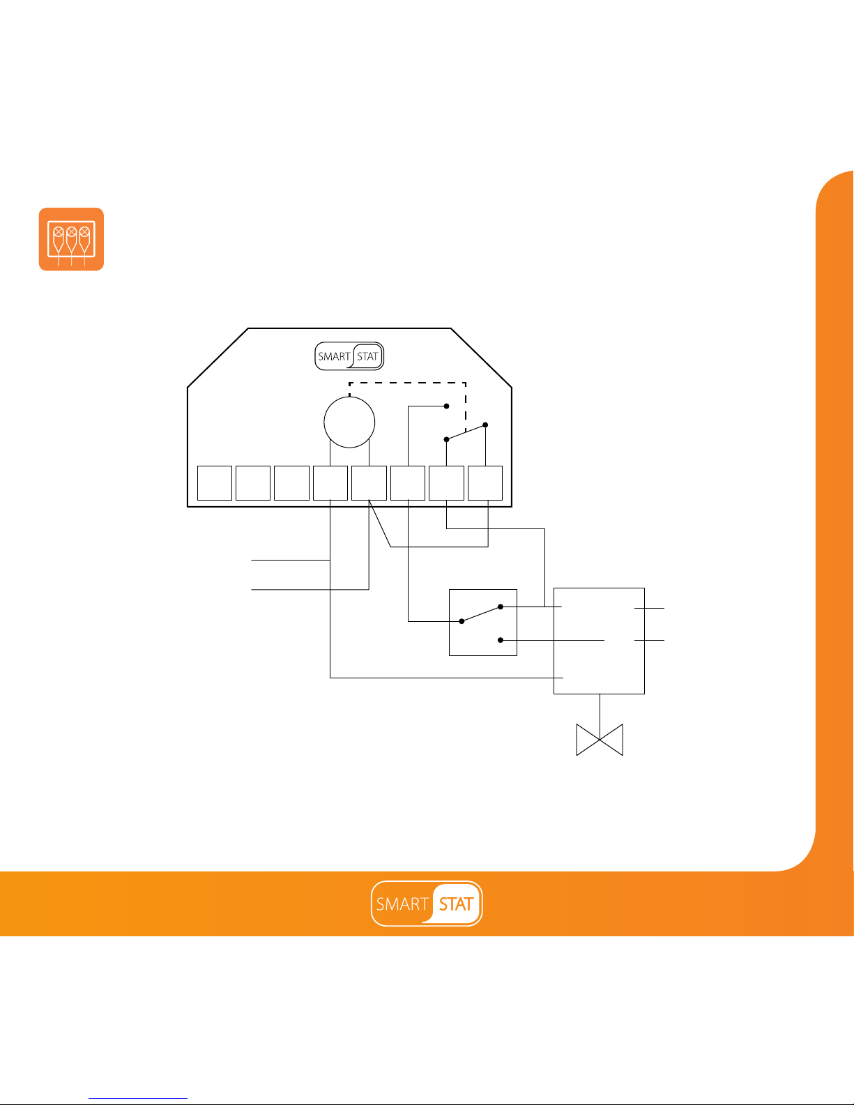
Wiring Diagram - Time Clock Mode
This product must only be installed by a qualified electrician
and comply with local installation regulations.
NCNO
RT1RT2
L
COM
Live
Neutral
230V Supply In
Hot Water Stat
Mid Position
Valve
To Heating On
Boiler Enable
N-
TIMER
GR WH
OR
BL
Page 39
39
Section Header
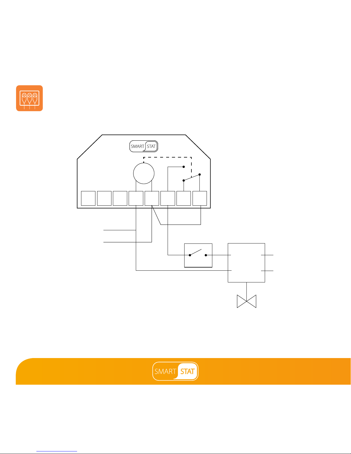
Wiring Diagram - Time Clock Mode
(S Plan)
This product must only be installed by a qualified electrician
and comply with local installation regulations.
Live
Neutral
230V Supply In
Hot Water Stat
End Switch
Boiler Enable
BR GR
BL OR
TIMER
NCNO
RT2
L
COM
-
RT1
N
Page 40
Want More Information?
PDF FAQ
Central Heating New Zealand Ltd
52 Pilkington Way, Christchurch
Ph: 0800 3571233
[email protected]
www.centralheating.co.nz
 Loading...