

Page 1

1
Model: DT-W
Model: DT-W
Page 2

2
Wireless Series
2Model: DT-W
Model: DT-W
Wireless Series1
Table of Contents
1
2
3-4
5-6
7-8
9
10-11
11-12
13-14
15
16
16
17
17
18
18
19-22
Product Image
Table of Contents
What is a Room Thermostat?
Installation Procedure
Installing the Batteries
Replacing the Batteries
Pairing with the RC1-W Receiver
Pairing with the UH1-W Wiring Centre
LCD Display
Temperature Display
Locking the Thermostat
Setting the Temperature
Frost Protection
Power On / O
Re-calibrating the Thermostat
Factory Reset
Optional Features
Page 3

43
Wireless Series Model: DT-W
What is a Room Thermostat?
If your heating system is a boiler with radiators, there will usually be only one room
thermostat to control the whole house. But you can have dierent temperatures
in individual rooms by installing thermostatic radiator valves (TRVs) on individual
radiators.
If you don’t have TRVs, you should choose a temperature that is reasonable for the
whole house. If you do have TRVs, you can choose a slightly higher setting to make
sure that even the coldest room is comfortable, then prevent any overheating in other
rooms by adjusting the TRVs.
Room thermostats need a free ow of air to sense the temperature, so they must not
be covered by curtains or blocked by furniture. Nearby electric res, televisions, wall
or table lamps may also prevent the thermostat from working properly.
A room thermostat simply switches the heating system on and o as necessary.
It works by sensing the air temperature, switching on the heating when the air
temperature falls below the thermostat setting, and switching it o once this set
temperature has been reached.
Setting a room thermostat to a higher temperature will not make the room heat up
any faster. How quickly the room heats up depends on the design & size of the heating
system.
Similarly reducing the temperature setting does not aect how quickly the room cools
down. Setting a programmable room thermostat to a lower temperature will result in
the room being controlled at a lower temperature, and saves energy.
The way to set and use your room thermostat is to nd the lowest temperature settings
that you are comfortable with, and then leave it alone to do its job.
The best way to do this is to set the room thermostat to a low temperature
– say 18°C , and then turn it up by 1°C each day until you are comfortable with the
temperature. You won’t have to adjust the thermostat further. Any adjustment above
this setting will waste energy and cost you more money.
Page 4
65
Wireless Series Model: DT-W
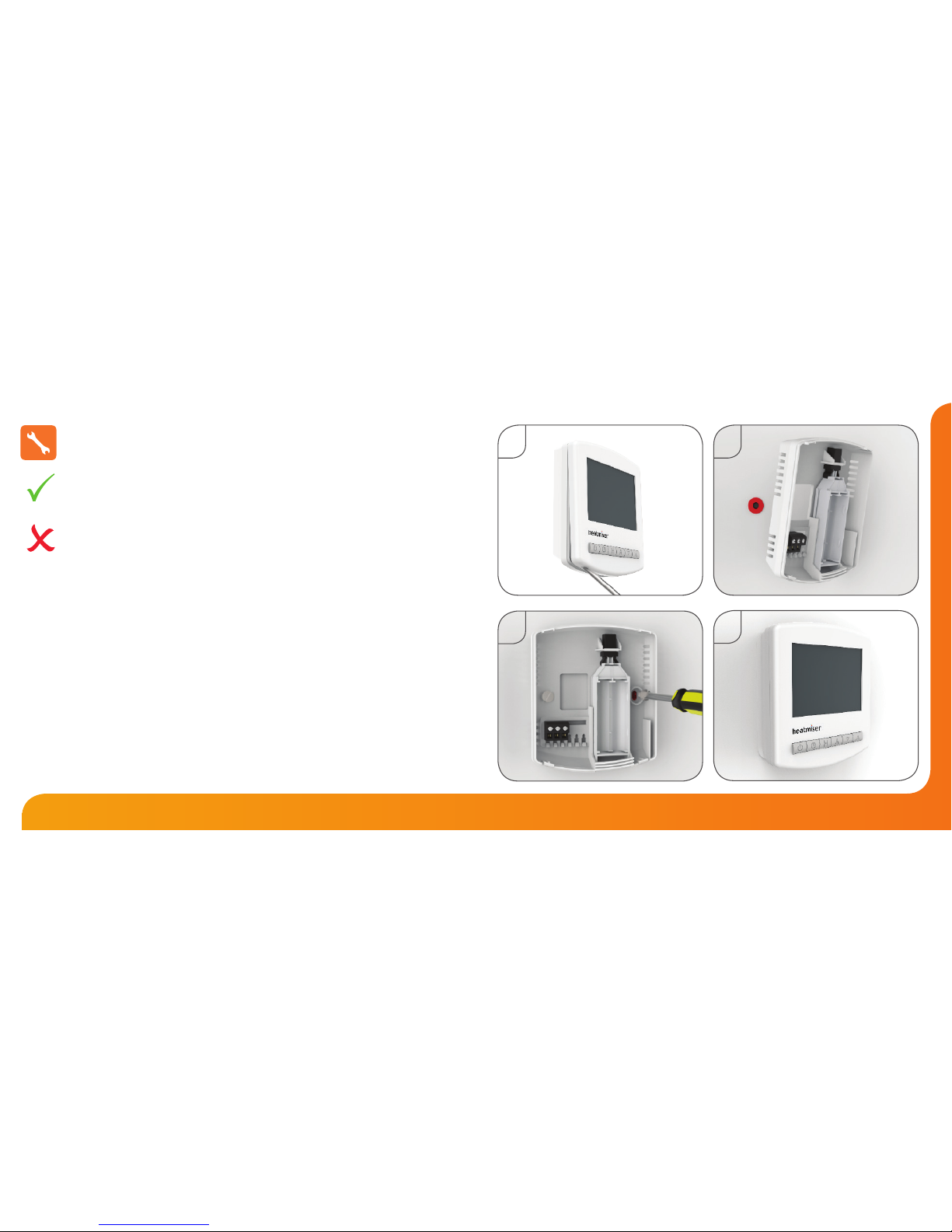
Installation Procedure
This wireless thermostat is designed to be surface mounted.
Step 1
Carefully separate the front half of the thermostat from the back plate by placing a
small at head terminal driver into the slots on the bottom face of the thermostat.
Step 2
Mark 2 hole positions on the wall using the backplate as a positioning template.
Drill at the marked positions and insert a wall plug into each hole.
Step 3
Screw the thermostat back plate securely on the wall.
Step 4
Clip the front of the thermostat back onto the thermostat back plate.
Do
Mount the thermostat at eye level.
Read the instructions fully so you get the best from our product.
Don’t
Do not install near to a direct heat source as this will aect functionality.
Do not push hard on the LCD screen as this may cause irreparable damage.
1
4
3
2
Page 5
87
Wireless Series Model: DT-W
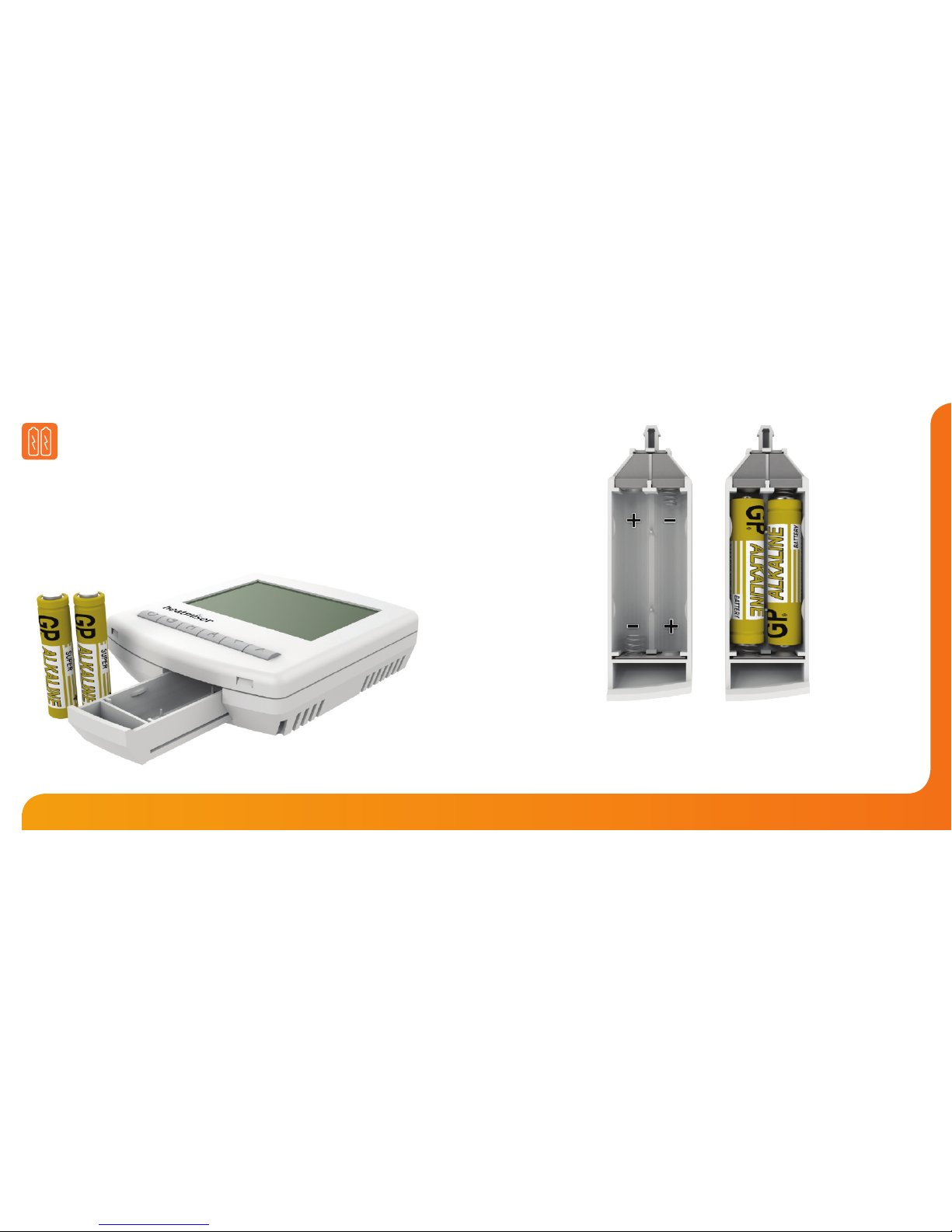
Installing the Batteries
2x AAA batteries have been supplied with this thermostat.
To access the battery holder, push and release the compartment door located on
the bottom face of the thermostat.
Insert the batteries in the empty battery holder, ensuring that each battery is
orientated for the correct polarity + / - .
Push the battery holder back inside the thermostat until it is secured
in its closed position.
Page 6
109
Wireless Series Model: DT-W
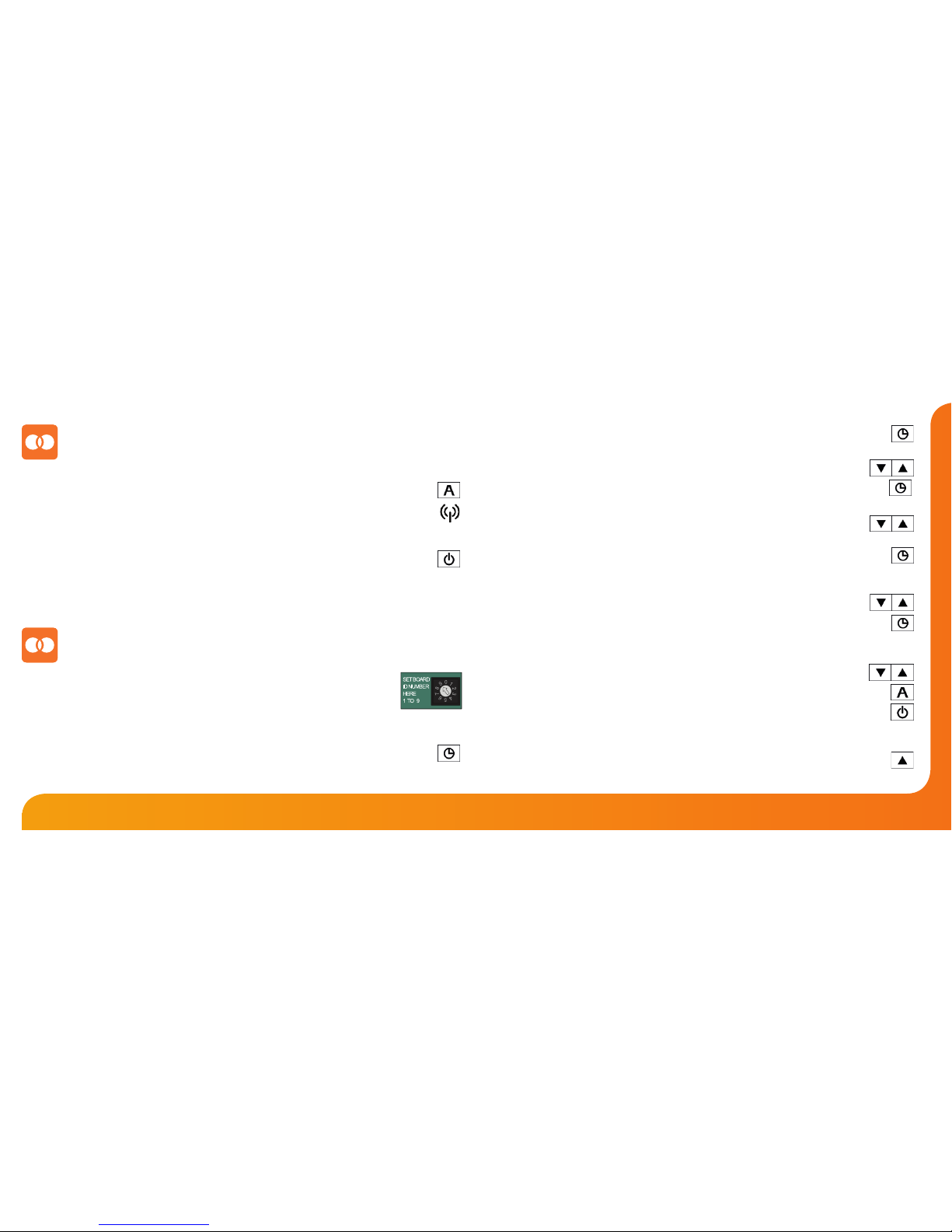
Pairing With the RC1-W Receiver
With the thermostat turned OFF:
• Press & hold the Clock button until you see two sets of numbers appear ...
• The small number 01 in the top right corner of the LCD is the feature number.
• Press Clock repeatedly until you see feature 06 (Receiver Type) ......................
The options within feature 06 are: 00 = UH1-W or 01 = RC1-W receiver.
• Use the Up/Down keys to set feature 06 to 01 (RC1-W) .............................
• Press Clock again until you see feature 07 (Receiver Address) .........................
• You can now select a Receiver Address from 01-32.
• Use the Up/Down keys to set feature 07 to 01 ...............................................
(You must set a unique receiver address for each receiver installed).
• Press Clock again until you see feature 08 (Zone number) ................................
• You are able to connect two DT-W thermostats to one RC1-W receiver.
• Use the Up/Down keys to select the zone this thermostat
controls (01 or 02) ....................................................................................................
• Press A to conrm settings and the display will go blank ..................................
If using with the UH1-W wiring centre, turn to page 11.
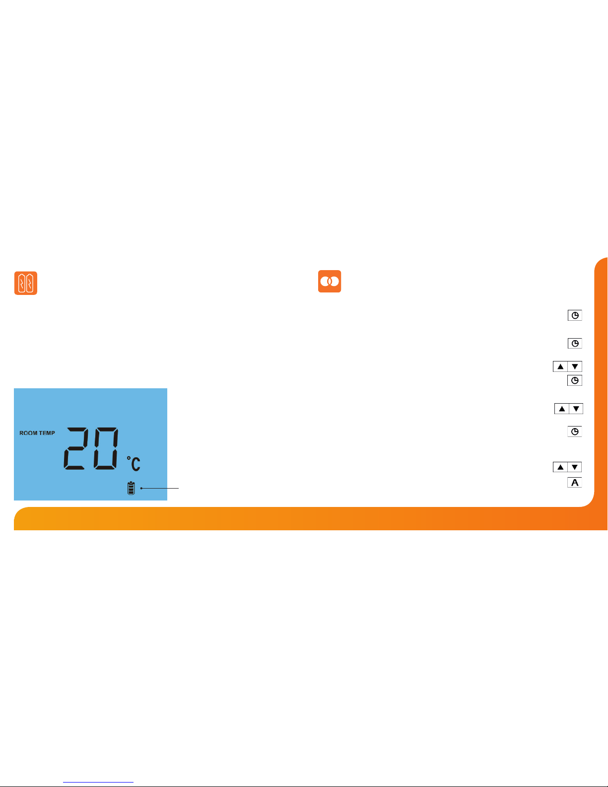
Batteries have a xed lifespan and will need to be replaced occasionally to
ensure the thermostat operates correctly.
The thermostat will inform you when the batteries need to be replaced by
displaying the battery icon on screen.
Note: You must replace the batteries within 1 minute of removal in order to retain
the current settings.
Replacing the Batteries
Battery Icon
(Flashes)
Page 7
1211
Wireless Series Model: DT-W
Pairing the Thermostat
Pairing With the UH1-W Wiring Centre
• On the receiver, press and hold the Pairing button until the Comms LED lights up.
• With the thermostat turned OFF, press & hold the A button for 5 seconds ...........
• The thermostat will send a signal for 1 minute and will ash the RF signal icon ...
• If pairing is successful, the Comms LED on the receiver will ash.
• Press the Power button on the thermostat once to conrm pairing ........................
If pairing is unsuccessful, check features 06 to 08 have been congured correctly.
To eliminate a possible signal issue, reposition the thermostat closer to the receiver and
repeat the pairing process again.
On the UH1-W wiring centre, take note of the number set on
the rotary switch (Board ID number 1-9).
Each UH1-W on the system needs to have a dierent ID number.
With the thermostat turned OFF:
• Press & hold the Clock button until 2 sets of numbers appear on screen ..............
• The small number 01 in the top right corner of the LCD is the feature number.
• Press Clock repeatedly until you see feature 06 (Receiver Type) .......................
The options within feature 06 are: 00 = UH1-W or 01 = RC1-W receiver.
• Use the Up/Down keys to set feature 06 to 00 (UH1-W) ..............................
• Press Clock again until you see feature 07 (UH1-W Board Address) ................
• Use the Up/Down keys to set the large digits to the board address
of the UH1-W. This is the number set on the UH1-W rotary switch...
(You must set a unique board address for each UH1-W installed).
• Press Clock again until you see feature 08 (Zone number, 01-08) ....................
• The UH1-W is an 8 zone receiver.
Use the Up/Down buttons to select the zone this thermostat
should be linked to ....................................................................................................
• Press Clock again until you see feature 09 .................................................................
(00 = Underoor heating, 01 = Radiators.)
• Use the Up/Down buttons to specify whether the thermostat is
controlling underoor heating or radiators .....................................................
• Press A to conrm settings and the display will go blank ....................................
• Press the Power button once to turn the thermostat back ON .........................
• Press the Up key to set the target temperature above the room
temperature; the ame symbol will appear and the assigned
zone on the UH1-W will be activated ..........................................................................
This indicates pairing between the thermostat and the UH1-W is successful.
Page 8
1413
Wireless Series Model: DT-W
1
2
5 6 7 9
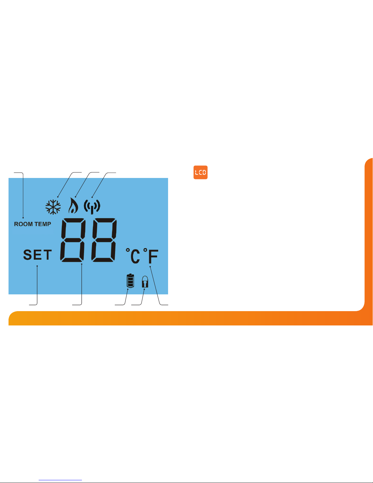
1. Room Temp - Indicates the current temperature sensor mode.
2. Frost Icon - Displayed when the thermostat is in frost protection mode.
3. Flame Icon - Displayed when the thermostat is calling for heat.
4. RF Icon - Flashes when the thermostat communicates with the receiver.
5. Set - Indicates when changes are being made to the temperature set point.
6. Current Temp - Indicates the current sensor temperature.
7. Battery Level - Indicates when the batteries require replacement.
8. Keypad Lock Indicator - Displayed when the keypad is locked.
9. Units of Temperature - Degrees Celsius or Fahrenheit.
LCD Display
3
4
8
Page 9
1615
Wireless Series Model: DT-W
Temperature Display
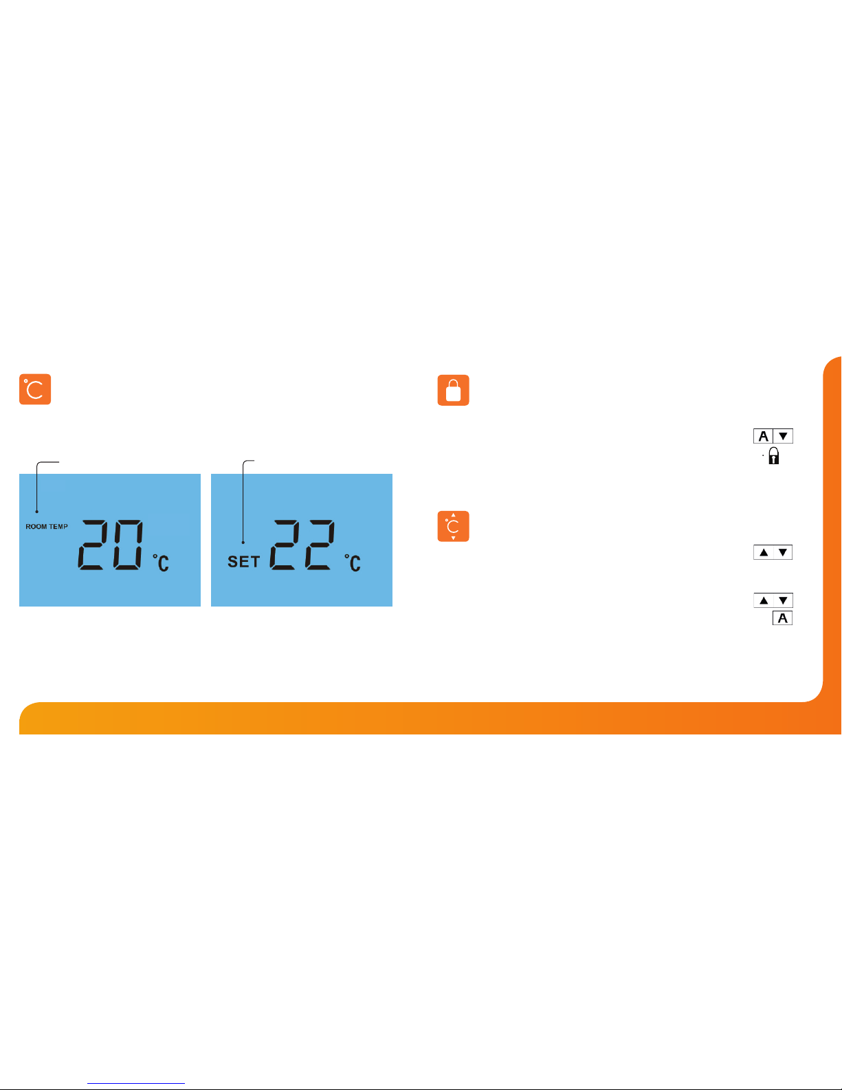
Room Temperature Set Temperature
This is the current room temperature. This is the temperature you are trying to
achieve in your home.
The temperature display information is driven by two dierent inputs; the sensor
measurement and the target temperature you have set.
Locking the Thermostat
The thermostat has a keypad lock facility. To activate the lock follow these steps.
• Press and hold the A and Down keys together for 10 seconds ..........
• You will see the lock symbol appear on screen .............................................
• To unlock, repeat the steps above until the lock symbol disappears.
Note: The keypad lock indicator is only displayed when the lock is active.
Temperature Control
The Up/Down keys allow you to adjust the set temperature .......................
When you press either key, you will see the word SET and the desired
temperature will be displayed on screen.
Use the Up/Down keys to adjust the SET value ..................................................
Press A to conrm settings and return to main display .............................................
Page 10
1817
Wireless Series Model: DT-W
Pressing the Power button once will place the thermostat in frost protect mode.
In this mode, the thermostat will display the frost icon and will only turn the heating
on should the room temperature drop below the set frost temperature (see page 19).
Should the heating be turned on whilst in frost mode, the ame icon will be displayed.
To cancel the frost protect mode, press the Power button once again.
Frost Mode
Heating On/O
The heating is indicated ON when the ame icon is displayed.
When the ame icon is absent, there is no requirement for heating to achieve the
set temperature but the thermostat remains active.
To turn the thermostat OFF completely, press and hold the Power button..........
The display and heating output will be turned OFF completely.*
Press the Power button once to turn the thermostat back ON .................................
*See Feature 3 on page 19
Re-calibrating the Thermostat
If you need to re-calibrate the thermostat, follow these steps.
• Press and hold the Power button to turn the thermostat OFF ............................
• Press and hold BOTH the Power and Down keys together until the
temperature appears on the screen ........................................................................
• Use the Up/Down keys to congure the new temperature ...........................
• Press A to conrm settings ...............................................................................................
• Press the Power button once to turn the thermostat back ON ..........................
Factory Reset
To perform a factory reset, follow these steps.
• Press and hold the Power button to turn the thermostat OFF ..........................
• Press and hold the Power and Up keys together until the LCD powers up.
All of the icons will be displayed on screen .........................................................
• When the icons have disappeared from the screen, the thermostat has
been successfully reset.
• Press the Power button once to turn the thermostat back ON .........................
The thermostat has a reset function to restore all settings to their factory defaults.
Page 11
2019
Wireless Series Model: DT-W
Optional Features Explained
THE FOLLOWING SETTINGS ARE OPTIONAL AND IN MOST CASES
NEED NOT BE ADJUSTED
Feature 01 - Temperature Format: This function allows you to select between °C and °F.
Feature 02 – Switching Dierential: This function allows you to increase the switching
dierential of the thermostat. The default is 1°C which means that with a set temperature
of 20°C, the thermostat will switch the heating on at 19°C and o at 20°C. With a 2°C
dierential, the heating will switch on at 18°C and o at 20°C.
Feature 03 – Frost Protect: You can set whether the thermostat will maintain the frost
temperature when the thermostat display is turned o. As a default, this is enabled.
Feature 04 – Frost Protect Temperature: This is the temperature maintained when the
thermostat is in frost mode. The range is 07 - 17°C. The default is 12°C and is suitable for
most applications.
Feature 05 – Output Delay: To prevent rapid switching, an output delay can be entered.
This can be set from 00 - 15 minutes. The default is 00 which means there is no delay.
Feature 06 – UH1-W or RC1-W receiver: The thermostat can work with our UH1-W 8 zone
wiring centre or RC1-W 2 channel receiver. This setting determines which is being used.
Feature 07 – Receiver Address: Within one building, up to 9 UH1-W’s or 32 RC1-W’s can be
used. Each receiver must have a unique receiver address (01-32).
Feature 08 – Zone Number: This is the zone number you are assigning the thermostat to
on either the UH1-W or the RC1-W receiver. 01 - 08 - UH1-W, 01 - 02 – RC1-W
Feature 09 – Underoor Heating or Radiator Zone (UH1-W Only):
This setting determines whether the thermostat will activate the pump & boiler output
on the UH1-W. If set to 00 the outputs will be activated. 00 = UFH, 01 = Radiators
Feature 10 – Fail Safe: If enabled, the thermostat will send a signal to the receiver every
20 minutes. Should the receiver fail to receive two signals, the receiver will activate the
output for 20% of the time. This is to protect the system against a loss of wireless signal
and in case the thermostat battery fails whilst you are away.
Feature 11 – Up/Down Temperature Limit: This function allows you to limit the use of
the up and down keys. This limit is also applicable when the thermostat is locked and so
allows you to give others limited control of the heating system.
Page 12
2221
Wireless Series Model: DT-W
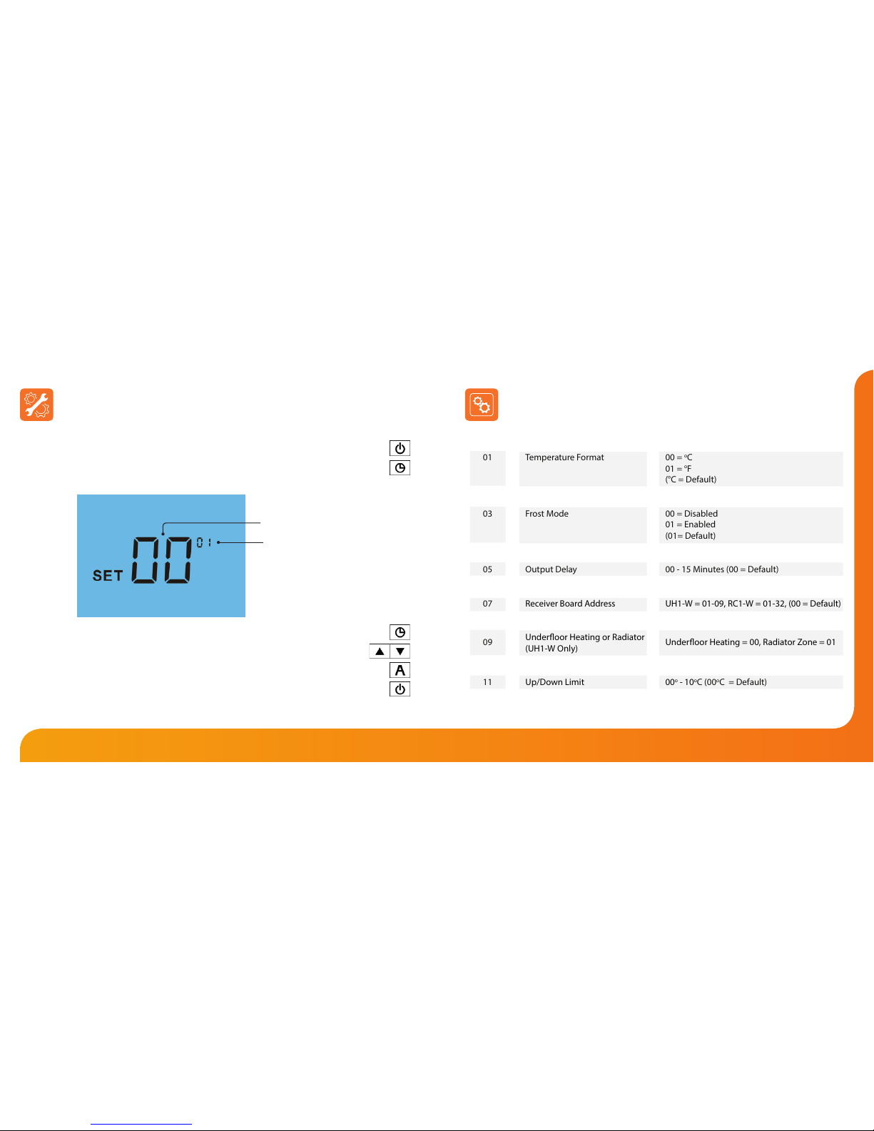
Optional Settings - Feature Table
01
02
03
04
05
06
07
08
09
10
11
FEATURE
Temperature Format
Switching Dierential
Frost Mode
Frost Protection Temperature
Output Delay
UH1-W or RC1-W Receiver
Receiver Board Address
Zone Number
Underoor Heating or Radiator
(UH1-W Only)
Fail Safe
Up/Down Limit
DESCRIPTION
00 = oC
01 = oF
(°C = Default)
01o - 03oC (01oC = Default)
00 = Disabled
01 = Enabled
(01= Default)
07o - 17oC (12oC = Default)
00 - 15 Minutes (00 = Default)
00 = UH1-W, 01 = RC1-W (00 = Default)
UH1-W = 01-09, RC1-W = 01-32, (00 = Default)
UH1-W = 01-08, RC1-W = 01-02
Underoor Heating = 00, Radiator Zone = 01
00 = Disabled, 01 = Enabled (01 = Default)
00o - 10oC (00oC = Default)
SETTING
Adjusting the Optional Settings
To adjust the optional settings, follow these steps.
• Press and hold the Power button to turn the thermostat OFF ..............................
• Press and hold the Clock button until the display appears as shown below ...
• Use the Clock button to cycle through the features .................................................
• Use the Up/Down keys to change the setting ....................................................
• Press A to conrm settings .................................................................................................
• Press the Power button once to turn the thermostat back ON .............................
Setting Value
Feature Number
Page 13
23
Wireless Series
Video
Twitter: heatmiseruk
Facebook:
facebook.com/thermostats
Want More Information?
Call our support team on: +44 (0)1254 669090
Or view technical specications directly on our website:
www.heatmiser.com
PDF FAQ
Heating Professionals:
Request a copy of our product
installation guide containing
detailed technical specications
for our complete product range:
www.heatmiser.com/guide
 Loading...