

Heatmiser DS1 User Manual
The Heatmiser DS1 dial type thermostat is suitable for conventional or
combi-boiler systems.
This thermostat incorporates the following functions;
• Adjustable Switching Dierential
• LED Heat and Power Indication
• 230v AC, 3A Switching
Want More Information?
Call our support team on:
+44 (0)1254 669090
Or view technical specications
directly on our website:
www.heatmiser.com
Introduction
1
4
Model: DS1
IN ORDER TO AVOID ANY RISK OF ELECTRIC SHOCK, TURN OFF THE POWER TO THE
HEATING SYSTEM.
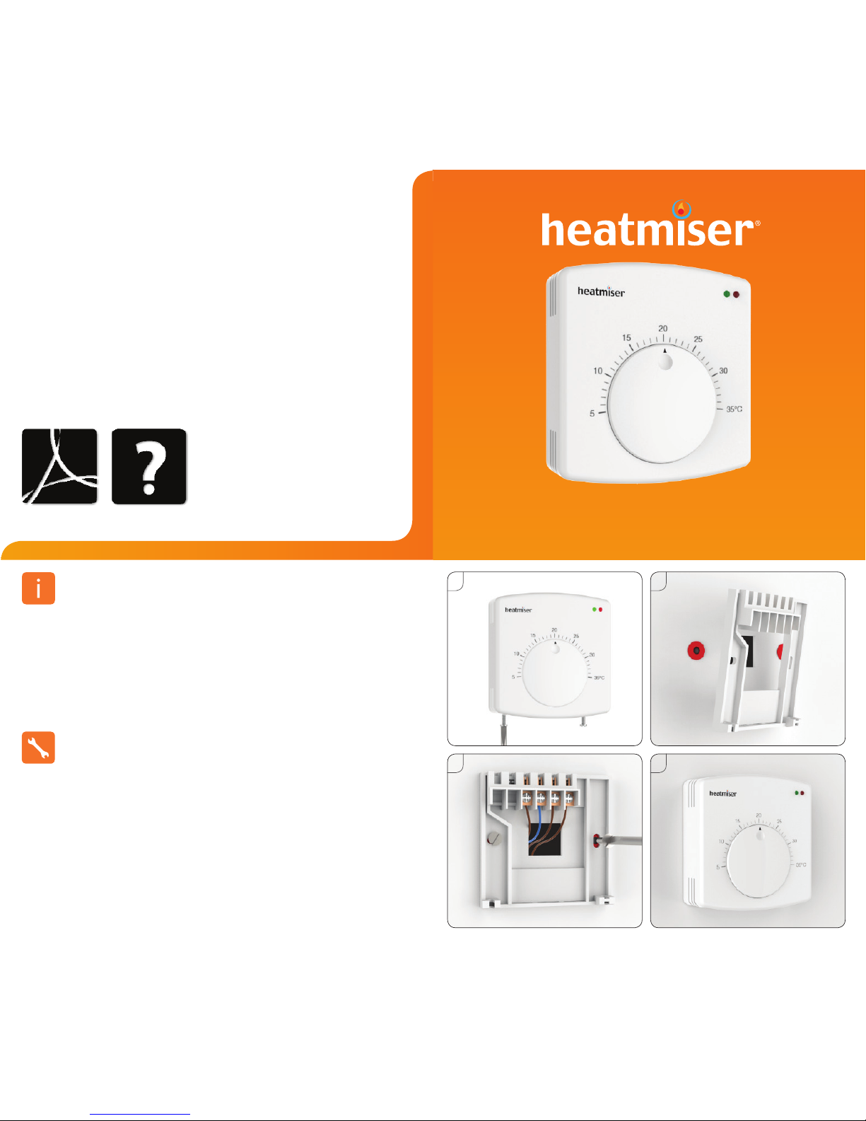
This dial thermostat is designed to be surface mounted.
1. Separate the front part of the thermostat by unscrewing securing screws on the
bottom face of the thermostat.
2. Mark 2 hole positions on the wall using the backplate as a positioning template. Drill at
the marked positions and insert a wall plug in to each hole.
3. Terminate the thermostat as per wiring diagram and screw the DS1 back plate to the
back box.
4. Reconnect the thermostat front plate and insert the securing screws.
Installation
2
3
PDF FAQ
To change the set point, rotate the dial until it points at the desired temperature.
Setting The Temperature
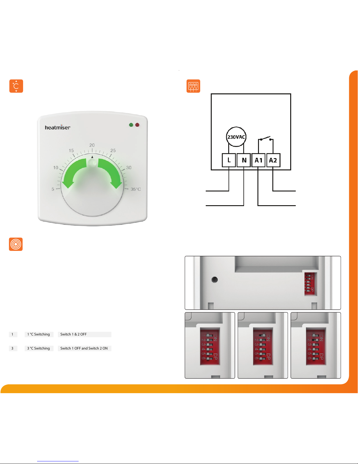
The Heatmiser DS1 oers 1, 2 and 3°C switching dierential.
With a 1°C switching dierential the heating will switch on 1°C below the set
temperature and will turn o when the set temperature is reached.
A 2°C will turn the heating on 2°C below the set temperature.
3°C will switch the heating on 3°C below the set temperature.
To set the dierential, you should set the DIP switches according to the table below.
The DIP switch can be accessed from the back of the thermostat (shown opposite).
Switching Dierential
1 °C Switching
2 °C Switching
3 °C Switching
1
2
3
Switch 1 & 2 OFF
Switch 1 ON and Switch 2 OFF
Switch 1 OFF and Switch 2 ON
Wiring Diagram - DS1 to Boiler Voltfree
230V Supply
For 230V
switched live to
boiler on A2
link L to A1
LS & LR ARE NORMALLY THE
ROOM THERMOSTAT CONNECTIONS
LR
LS
DS1
2 31
 Loading...