

Heatmaster HVF-36, HVF-42, HVF-BM-36, HVF-BM-42 Installation, Operation And Maintenance Manual
VENT-FREE FIREBOX
MODEL: HVF-36 and HVF-42
&
MODEL: HVF-BM-36 AND HVF-BM-42
INSTALLATION, OPERATION AND MAINTENANCE MANUAL
FOR USE ONLY WITH A LISTED GAS-FIRED
UNVENTED DECORATIVE ROOM HEATER NOT
TO EXCEED 40,000 BTU/H.
DO NOT BUILD A WOOD FIRE
.
Carefully review the instructions supplied with the decorative type unvented
room heater for the minimum fireplace size requirements.
DO NOT INSTALL AN APPLIANCE IN THIS FIREBOX
UNLESS THIS FIREBOX MEETS THE
MINIMUM DIMENSIONS REQUIRED FOR THE INSTALLATION.
WARNING: If the information in this manual is not followed exactly, a fire or explosion may
result causing property damage, personal injury or loss of life.
INSTALLER: Leave this manual with the appliance.
CONSUMER: Retain this manual for future reference.
16-1015 03-2009

SAFETY CODES AND STANDARDS
The design of this firebox has been tested and approved by the C.S.A. in accordance with ANSI Z21.91b-2007 UNVENTED
FIREBOX ENCLOSURES FOR GAS-FIRE UNVENTED DECORATIVE ROOM HEATERS. This firebox is UNIVERSALLY
LISTED for use with the compatibly sized decorative type unvented room heaters, which comply with standard Volume II
Z21.11.2 of the American National Standards Institute. This manual serves only as a basic guideline for installation of this
firebox and gas piping. The complete installation must be in accordance with local codes and ordinances or, in the absence
of local codes, with American National Standards Institute Fuel Gas Code Z223.1/NFPA 54.
SELECTING A LOCA TION FOR THE FIREBOX
This firebox may be installed at 0” clearance to combustibles at its bottom and top framing spacers. See installation
instructions for other clearances.
It is imperative that adequate clearances around air openings into and away from this firebox be maintained. To ensure
these clearances, do not place any object closer than 24 inches directly in front of the firebox. Do not block any openings in
the firebox.
See optional location in this manual for the many ways in which this unit could be located in the home. When the firebox is
installed directly on carpeting, tile, or other combustible material other than wood flooring, the firebox shall be installed on a
metal or wood panel extending the full width and depth of the enclosure.
INSTALLATION INFORMATION
IMPORTANT: Before beginning the installation, check with local building officials to assure compliance with local
regulations and codes, and to obtain any required permits.
A qualified installer or service agency must perform installation and service. All instructions should be read and understood
prior to installing the firebox. Protective wear such as safety glasses to protect eyes and work gloves should be worn during
the installation.
Heavy stone or brick facings and/or hearth extensions may require additional foundation support not located near a loadbearing wall.
The unit may be installed at zero-clearance to the floor and top framing spacers. Warning: Do not notch framing or alter the
spacers. The back of the unit needs to have a 1” clearance from combustible material.
Check to see if the unit is square prior to securing. Secure the unit to framing using the built-in nailing flanges. The nailing
flanges have been designed to allow the application of ½” wallboard or plywood flush with the firebox face. Directly above
the unit, noncombustible wallboard should be used as specified in this instruction manual.
Do not fill the spaces around the firebox with insulation or other materials. The floor under the unit and the area above the
top framing spacers should be insulated. This will reduce cold air infiltration, reduce heat loss and increase the heating
efficiency of the product.
Provisions for adequate combustion and ventilation air must be provided for the decorative type unvented room heater to be
installed in this firebox. Refer to the instructions supplied with the decorative type unvented room heater.
2

ATTENTION INSTALLER:
1. Attach with fasteners the label that was supplied with the unvented fireplace insert to the inside of the solid-fuel burning
fireplace or listed unvented firebox enclosure into which the unvented fireplace insert is installed.
2. DO NOT cut any sheet metal parts of the solid-fuel burning fireplace or listed unvented firebox enclosure in which the
unvented fireplace insert is to be installed.
3. If the factory-built fireplace has no gas access hole(s) provided an access hole of 1.5 inch (37.5mm) diameter or less
may be drilled through the lower sides or bottom of the firebox in a proper workmanlike manner. This access hole
must be plugged with non-combustible insulation after the gas supply line has been installed.
4. The glass doors, screen rails, screen mesh and solid-fuel log grates can be removed from the fireplace before
installing the unvented fireplace insert.
5. If attached by fasteners the smoke shelves, shields and baffles may be removed.
6. The trim panels or surrounds shall not seal ventilation openings in the fireplace.
7. Make sure to leave adequate clearances for accessibility for purposes of servicing and proper operation.
8. Combustible flooring installation: When the vent free firebox is installed directly on carpeting, tile, or other combustible
material other than wood flooring, the vent free firebox shall be installed on a metal or wood panel extending the full
width and depth of the vent free firebox.
9. Solid fuels shall not be burned in a fireplace where an unvented room heater is installed.
3
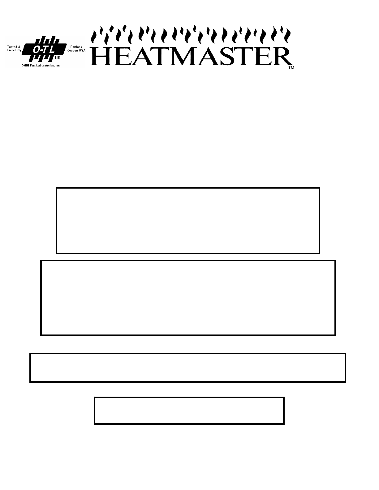
OPTIONAL LOCATIONS FOR FIREBOX
FLUSH
COR
N
ER
FULL ROOM
PROJECTION
PARTIAL ROOM
PROJECTION
DIVIDER
ROOM
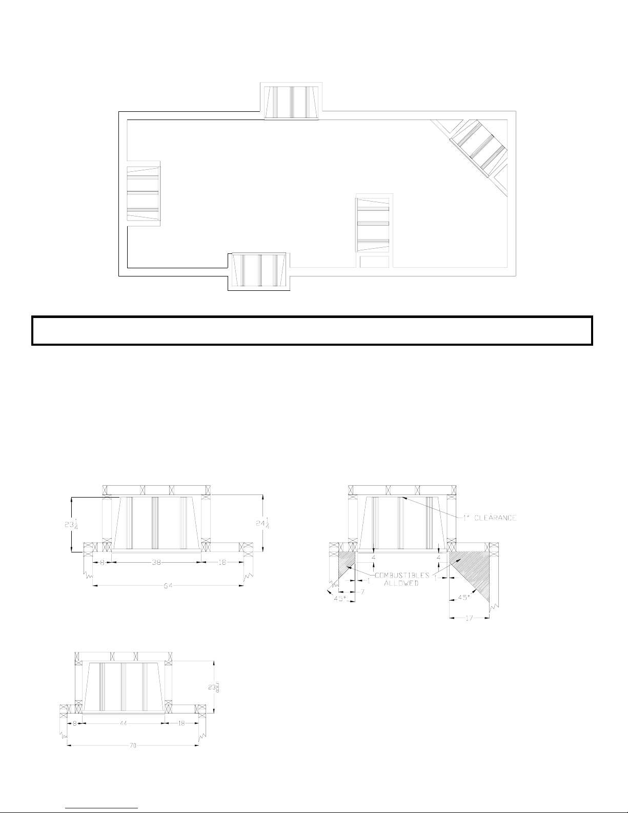
CLEARANCES
Clearance to one perpendicular combustible side wall may be 8 inches minimum. The minimum distance between two
perpendicular combustible side-walls for HVF-36 and HVF-BM-36 is 64 inches. The minimum distance between two
perpendicular combustible side-walls for HVF-42 and HVF-BM-42 is 70 inches. It is imperative that adequate clearances
around air openings into and away from this firebox be maintained. To ensure these clearances, do not place any object
closer than 24 inches directly in front of the firebox. Do not block any openings in the firebox.
COMBUSTIBLE SIDE WALL INSTALLATION COMBUSTIBLE SIDE WALL PLACEMENT
HVF-36 & HVF-BM-36 FOR HVF-36 & HVF-BM-36 & HVF-42 & HVF-BM-42
COMBUSTIBLE SIDE WALL INSTALLATION
HVF-42 & HVF-BM-42
4
 Loading...