

Heatmaster HMVF-ECO 24LP, HMVF-R 24NG, HMVF-ECO 24NG, HMVF-ECO 30LP, HMVF-ECO 36LP Installation And Operating Instructions Manual
...Page 1
Installation and Operating Instructions for Natural & LP Gas
Unvented Gas Log Heater
HMVF-R-24 & 30/36”
HMVF-IPI-ECO 24” & 30/36”
ANSI Z21.11 2-2016 APPROVED / ANSI Z21.60 -2017 CSA 2.26 2017
State and local codes may only allow operation of this appliance in a vented configuration. Check your local and state codes.
WARNING: FAILURE TO FOLLOW THESE INSTRUCTIONS CAREFULLY AND WITHOUT
ERROR OR FAILURE TO HEED ANY AND ALL WARNINGS IN THESE INSTRUCTIONS CAN
RESULT IN AN EXPLOSION, FIRE OR THE PRODUCTION OF CARBON MONOXIDE GAS
WHICH CAN CAUSE PROPERTY DAMAGE, BODILY INJURY OR DEATH.
WARNING
or explosion may result, causing property damage, personal injury or loss of life.
Do not store or use gasoline or other flammable vapors and liquids in the vicinity of this or any
other appliance.
WHAT TO DO IF YOU SMELL GAS:
•
Do not try to light any appliance.
•
Do not touch any electrical switch.
•
Do not use any telephone in your building.
•
Immediately call your gas supplier from a neighbor’s telephone.
•
Follow the gas supplier’s instructions.
•
If you cannot reach your gas supplier, call the fire department.
Installation and service must be performed by a qualified installer, service agency or the gas
supplier.
This is an unvented gas-fired heater. It uses air (oxygen) from the room in which it is installed. Provisions for adequate combustion and ventilation air must be provided. Refer to
page 8.
This appliance is intended for supplemental heating.
“This appliance may be installed in an aftermarket, permanently located, manufactured (mobile)
home, where not prohibited by local codes. This appliance is only for use with the type of gas
indicated on the rating plate. This appliance is not convertible for use with other gases.”
If the information in this manual is not followed exactly, a fire
IMPORTANT: READ INSTRUCTIONS CAREFULLY BEFORE
BEGINNING INSTALLATION OF THIS ROOM HEATER.
IM-115
10/2018
INSTALLER: Leave this manual with the appliance.
CONSUMER: Retain this manual for future reference.
1
Page 2
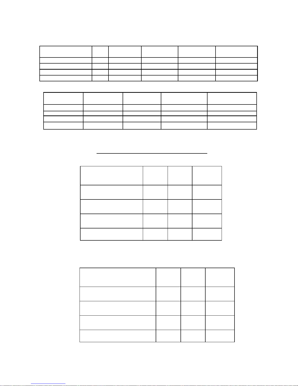
PRODUCT SPECIFICATIONS
Product
Inlet BTU Nat 39,000 39,000 40,000 40,000
Min. BTU Nat 25,000 25,000 26,000 27,000
Product
Inlet BTU 39,000 40,000 40,000 40,000
Min. BTU 26,000 25,000 28,000 26,000
HMVF-ECO 24LP HMVF-ECO 24NG HMVF-ECO 30/36LP HMVF-ECO 30/36NG
HMVF-R 24LP HMVF-R 24NG HMVF-R 30/36LP HMVF-R 30/36NG
FIREPLACE and HEARTH DIMENSIONS
HMVF-R Minimums
24" 30"
36"
Height 18” 20” 20”
Width of Front Opening 29" 38 1/2” 48"
Depth 14" 14" 14"
Width of Rear Opening 20” 20” 20”
HMVF-IPI-ECO Minimums
Height
24" 30"
18” 20”
36"
20”
Width of Front Opening 32" 38 1/2” 48"
Depth 15" 15" 15"
Width of Rear Opening 20” 20” 20”
Use manufacturer’s installation and clearance requirements as defined in their manual.
2
Page 3
Important safety information
WARNING
•
Any change to this heater or its controls can be dangerous and void any warranty.
•
Do not allow fans to blow directly into fireplace. Avoid drafts that alter
burner flame patterns.
•
Do not use a blower insert, heat exchanger insert or any other accessory not approved
for use with this heater.
•
Improper installation or use of this heater can cause serious injury or death
from fire, burns, explosion or carbon monoxide poisoning.
Children and adults should be alerted to the hazard of high surface temperature
and should stay away to avoid burns or clothing ignition.
1. Due to high temperatures, the heater should be located out of traffic and away from furniture and
draperies.
2. Children and adults should be alerted to the hazard of high surface temperature and should stay away
to avoid burns or clothing ignition.
3. Young children should be carefully supervised when they are in the same room as the heater.
4. Do not place clothing or other flammable material near the fireplace when the heater is in use.
5. Any safety screen or guard removed for servicing must be replaced prior to operating the heater.
6. Installation and repair should be done by a qualified service person.
7. To prevent malfunction and/or sooting, an unvented gas heater should be cleaned at least annually by a
professional service person. More frequent cleaning may be required due to excessive lint from carpeting, etc. It is imperative that control compartments, burners and circulating air passageways be kept
clean.
8. CARBON MONOXIDE POISONING: Early signs of carbon monoxide poisoning are similar to the
flu with headaches, dizziness and/or nausea. If you have these signs, obtain fresh air immediately.
Have the heater serviced as it may not be operating properly.
9. The installation must conform with local codes or, in the absence of local codes, with the National Fuel
Gas Code, ANSI Z223.1/NFPA54 or the CSA B149.1 Natural Gas and Propane Installation Code.
10. This unit complies with ANSI Z21.11.2-2016 Unvented heaters and also complies with
ANSI Z21.60-2017 Decorative Vented appliances for Solid Fuel Burning fireplaces. State and local
codes may only allow operation of this appliance in a vented configuration. Check your state or
local codes. For vented operation, see “Vented Instructions” in this manual.
11. Do not install the heater in a bedroom or bathroom.
12. Correct installation of the logs, proper location of the heater and annual cleaning are necessary to
avoid potential problems with sooting. Sooting, resulting from improper installation or operation,
can settle on surfaces outside the fireplace. See log placement instructions for proper installation.
13. Avoid any drafts that alter burner flame patterns. Do not allow fans to blow directly into the fireplace.
Do not place a blower inside burn area of the firebox. Ceiling fans may create drafts that alter burner
flame patterns. Sooting and improper burning will occur.
14. This is an unvented Gas-fired heater. It uses air (oxygen) from the room in which it is installed.
Provisions for adequate combustion and ventilation air must be provided. Refer to installation
guidelines.
15. Keep appliance area clear and free from combustible materials, gasoline and other flammable
vapors and liquids.
3
Page 4
Do not use this room heater if any part has been under water. Immediately call a qualified service
technician to inspect the room heater and to replace any part on the control system and any gas
control which has been underwater.
This room heater is for installation in a solid fuel burning fireplace or listed unvented firebox enclosure only.
A fireplace screen must be in place when the appliance is operating and, unless other provisions for
combustion air are provided, the screen shall have an opening (s) for introduction of combustion air.
Any glass door should be fully opened when the appliance is in operation.
Important safety information cont
WARNING
rating plate. This appliance is not convertible for use with other gases.
WARNING
This appliance is only for use with the type of gas indicated on the
This appliance is equipped for (natural or propane) gas. Field con-
version is not permitted.
This appliance may be returned to manufacturer for conversion.
WARNING
Installation and repair should be done by a qualified service person.
The appliance should be inspected before use and at least annually by
a professional service person. More frequent cleaning may be required due to extensive lint from carpeting, bedding material, etc. It is imperative that control compartments, burners and circulating air passageways of the appliance be kept clean.
WARNING
“Failure to keep the primary air opening (s) of the burner (s) clean
may result in sooting and property damage”.
Solid fuels shall not be burned in a fireplace in which an unvented room heater is installed.
Any outside air ducts and/or ash dumps in the fireplace should be permanently closed at time
of appliance installation.
Clearances around air openings of fireplace must be kept clear. Do not stack anything in
front of air vents or fireplace openings.
WARNING
This appliance is for installation only in a solid fuel burning masonry or UL 127
Factory-built fireplace or in a listed unvented firebox enclosure. It has been design
certified for these installations. Exception: DO NOT install this appliance in a factory-built fireplace
that includes instructions stating it has not been tested or should not be used with unvented gas logs.
4
Page 5
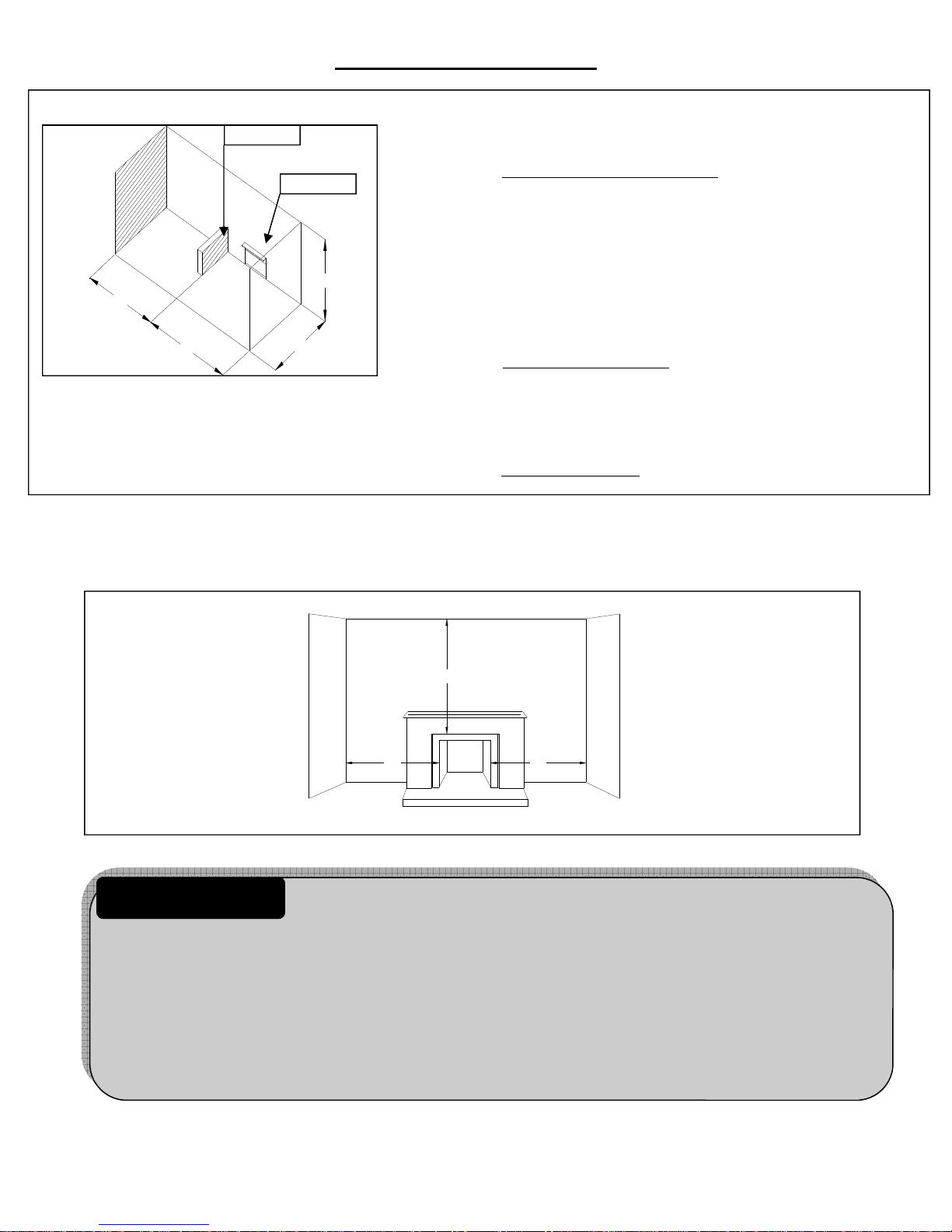
General Installation Information
The following formula can be used to determine the maximum heater
Counter
Fireplace
rating per the definition of confined space:
BTU/HR= (L
50
1
+
L2) FT X (W)FT X (H)FT X 1000
Example: Refer to Figure 1. Two (2) connecting rooms with and open
area between , with the following dimensions.
L1 = 15
L
H
2
L
1
W
L2 = 12 ’
W = 12 ’
H = 8 ’
(15
1/2 +
12 ) x (12) x (8) x 1000 = 52800 btu./hr
1/2
50
Figure 1. Example of large room with 1/2 wall
divider.
If there was a door between the two rooms the calculation would be based
only on the room with the heater.
(15
1/2
) x (12) x (8) x 1000 = 27760 btu./hr
50
Sidewall and ceiling clearances
The sides of the fireplace opening must be at least 16” from any combustible wall. The ceiling must be at
least 42” from the top of the fireplace opening.
Figure 2. Sidewall
and Ceiling Clearances.
Right Side
Left Side
WARNING
42"
Front
16"16"
The dimensions shown in Figure 2 and defined in the fireplace manufacturer’s instructions are minimum clearances to maintain in installing this heater. Left and right
clearances are determined when facing the front of the heater.
When heater is installed into a unvented firebox, minimum clearances as specified by the unvented firebox
manufacturer must be met.
Follow these instructions carefully to ensure safe installation. Failure to follow instructions exactly can create
a fire hazard.
5
Page 6
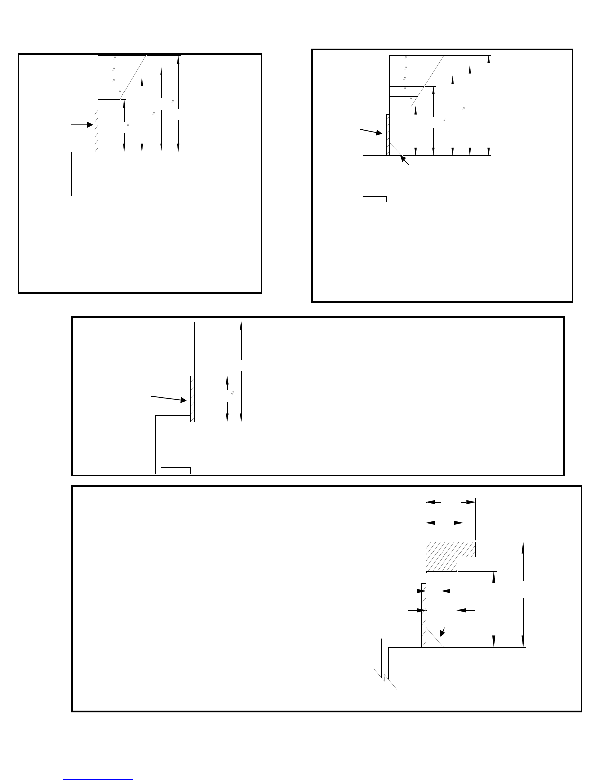
CLEARANCE/ HEIGHT REQUIREMENTS
10
8
6
2 1/2
24 5/8
Heat resistant
material
Figure 3.
Minimum Mantel Clearance with No Hood.
Example: The bottom of a mantel may project from
the wall a minimum of 14” above the opening. The
top side of the mantel may project a maximum of
6” at a minimum of 20-1/2” above the opening.
20 1/2
14
28"
10” and Less
12
10
8
6
2 1/2
Heat resistant
material
Hood
Figure 4.
Minimum Mantel Clearance with Hood.
Example: A mantel may project from the wall
a maximum of 2-1/2” at a minimum of 8”
above the opening and a maximum of 6” at
a minimum of 14-1/2” above the opening.
18 5/8
14 1/2
8"
26"
22 1/2"
28"
Heat resistant
material
Figure 6.
Is an example of an unsafe mantel installation. This
mantel projects 4” at 8” above the opening, exceeding
the maximum acceptable distance of 2-1/2”. The
mantel also projects 7” at 14-1/2” above the opening,
exceeding the maximum acceptable distance of
6”.
If your mantel profile is unsafe, you may either:
Raise the mantel to an acceptable height or,
Remove the mantel.
12
Figure 5. Minimum Mantel Clearance with No
Hood.
Example: The bottom of the mantel may project
from the wall a maximum of 10” at a
minimum of 28” above the opening.
7"
6"
Mantel
2 1/2"
Minimum of 8” heat resistant
material
4"
Hood
8"
14 1/2"
Page 7
6
Page 7

CLEARANCE/ HEIGHT REQUIREMENTS cont
Heat resistant material ( minimum requirements) with
8” or more of heat
8" or more of
resistant material
heat resistant
material
wooden mantel or other combustible projection:
To install the heater with a wooden mantel, shelf or
other combustible projection above, first measure
the heat resistant material shown in Figure 7.
Heater in Fireplace
or Firebox
Figure 7.
Measuring heat resistant material for mantel.
Heat Resistant Material Requirements for safe installation with wooden mantel, shelf
measurement or other combustible projection.
12” or more Hood not required. Observe profiles
8” to less than 12” Install hood and observe profiles
Less than 8” Extend heat resistant material to at
Figure 8.
Minimum
clearance above
combustible
flooring.
Hood not required. Observe profiles
(side elevations) shown in Figure 3.
shown in Figure 4. Or extend heat
resistant material to at least 12”
observe profiles shown in Figure 3.
least 8” . Install hood and observe
profiles shown in Figure 4. Or
extend heat resistant material to at
least 12” and observe profiles shown
in Figure 3.
(side elevations) shown in Figure 5.
Install hood and observe profiles
shown in Figure 4. Or extend heat
resistant material to at least 12”
observe profiles shown in Figure 5.
Extend heat resistant material to at
least 8” . Install hood and observe
profiles shown in Figure 4. Or
extend heat resistant material to at
least 12” and observe profiles shown
in Figure 3.
FLOOR CLEARANCE
This gas log heater must be installed at least 5” above any combustible flooring material, such as
carpeting or tile, which is closer than 14” to the base of the fireplace. This minimum distance must be
maintained from the top surface of carpeting, tile, etc. Refer to Figure 8.
Figure 9.
Minimum
clearance above
combustible
flooring with
non-combustible
material installed
at base of fireplace.
Combustible
material
5” Minimum
5" Minimum
Combustible
material
14” Minimum
14" Minimum
This gas log heater may be installed nearer to the floor if a minimum of 14” of noncombustible material
such as slate or marble is installed between the base of the fireplace and the combustible flooring.
Refer to Figure 9.
7
Page 8

General Instructions
PROVISIONS FOR ADEQUATE COMBUSTION AND VENTILATION AIR
This heater shall not be installed in a confined space or unusually tight construction unless
provisions are provided for adequate combustion and ventilation air.
The National Fuel Gas Code ANSI Z223.1/NFPA54 defines a confined space as a space whose
volume is less than 50 cubic feet per 1,000 Btu per hour (4.8m
of all appliances installed in that space and an unconfined space as a space whose volume is not less that
50 cubic feet per 1,000 Btu per hour (4.8m
3
per kw) of the aggregate input rating of all appliances
3
per kw) of the aggregate input rating
installed in that space. Rooms communicating directly with the space in which the appliances are
installed, through openings not furnished with doors, are considered a part of the unconfined space.
Unusually tight construction is defined as construction where:
a) Walls and ceiling exposed to the outside atmosphere have a continuous water vapor retarder with
a rating of 1 perm ( 6 x 10-11 kg per-pa-sec-m2) or less with openings gasketed or sealed, and
b) Weather stripping has been added on openable windows and doors, and
c) Caulking or sealant are applied to areas such as joints around windows and door frames,
between sole plates and floors, between wall-ceiling joints, between wall panels, at penetrations
for plumbing, electrical, and gas lines, and at other openings.
The installation of appliances designed for manufactured home or mobile home installation must conform
with Manufactured Home Construction and Safety Standard Title 24 CFR, Part 3280, in the United States, or
when such standard is not applicable, ANSI/NCSBCS A225.1/NFPA 501A, Manufactured Home Installations
Standard.
WARNING
If the area in which the heater may be operated is smaller than that defined as an un-
confined space or if the building is of unusually tight construction, provide adequate
combustion and ventilation air by one of the methods described in the “National Fuel Gas Code, ANSI
Z223.1/NFPA 54, Section 5.3” or applicable local codes.
WARNING
If the area in which the heater may be operated does not meet the required volume for
indoor combustion air, combustion and ventilation air shall be provided by one of the
methods described in the National Fuel Gas Code, ANSIZ223.1/NFPA 54, the International Fuel Gas
Code or other applicable codes.
Keep burner and control compartment clean. See Installation and Operating Instructions accompanying heater.
8
Page 9

FIREPLACE PREPARATION
Before fully installing the unit:
•
Turn OFF the gas supply to the fireplace or firebox.
•
Seal any fresh air vents and/or ash clean-out doors located on the floor or wall of the fireplace. If left
unsealed, drafting may cause pilot outage or sooting. Use a heat resistant sealant. Do not seal the
chimney flue damper.
Before installing in a solid fuel burning fireplace, the chimney flue
and firebox must be cleaned of soot, creosote, ashes and loose paint by a
qualified chimney cleaner.
WARNING
INSTALLING VENTED APPLICATIONS (OPTIONAL)
Manual and Remote controlled gas logs may be installed as a vented decorative log set in compliance with
ANSI Z21.60 and National Fuel Gas Code, Section 6.6. Since the gas logs are operated with the damper
open, non-combustible material and minimum mantel requirements do not apply.
This appliance is for installation only in a solid fuel burning fireplace
(masonry of manufactured fireplace) with a working flue and
constructed of non-combustible material.
WARNING
Before installing the appliance:
•
Turn OFF the gas supply to the fireplace or firebox.
•
Have the fireplace floor and chimney professionally cleaned to remove ashes, soot, creosote or other
obstructions. Have this cleaning performed annually after installation.
•
Seal any fresh air vents and/or ash clean-out doors located on the floor or wall of the fireplace. If left
unsealed, drafting may cause pilot outage or sooting. Use a heat resistant sealant. Do not seal the
chimney flue damper.
Install and operate the appliance as directed in this manual.
Damper Stop Installation:
A damper stop must be provided with the unit.
Contact your dealer to obtain one. The damper
stop must be installed as shown in Figure 10 to prevent full closure of the fireplace damper blade and
provide a minimum 29 sq. in. flue opening.
Figure 10.
Damper stop installation.
9
Page 10

PLACING GLOWING EMBER MATERIAL.
WARNING
or material not supplied with heater. Replace only with Thermafiber, Granulated HP. Part No.
F-EMBERS.
All previously applied loose material must be removed prior to reapplication.
Apply all loose material per instruction manual. DO NOT apply extra material
DO NOT ATTEMPT TO LIGHT THE BURNER BEFORE
GLOWING EMBER MATERIAL IS IN PLACE.
WARNING
Failure to position the supplied material in accordance with these
instruction or failure to use only the materials supplied specifically with
this heater may result in property damage or personal injury.
Step 1.
Loosely place glowing ember material under
the top burner as shown below.
NOTE:
It is imperative that enough ember
material be loosely placed at the top
of the middle burner to insure proper ignition of ember bed.
NEVER PACK OR ADD ANY
MATERIAL ON THE BURNER
OTHER THAN WHAT IS SUPPLIED WITH YOUR SYSTEM .
Step 2. Place glowing ember material along the sides of the middle burner. Place
glowing embers along the sides of the bottom burner, all the way across.
10
Page 11

PLACING GLOWING EMBER MATERIAL. (Cont’)
Step 3. Pull embers apart and gently place thin pieces on top of the middle burner and all
the way across the bottom burner. Do not pack.
Start like this
Finish like this
Step 4. Continue pulling embers apart and gently placing thin pieces until the mesh part of
the burner is covered. When this is completed is should look like the picture below.
Do not pack.
It is imperative that ember material be placed correctly for proper ignition of the middle and bottom
burners.
This burner WILL NOT light properly without the
glowing embers in place.
All previously applied loose material must be removed prior to reapplication.
WARNING
PLACEMENT OF PLATINUM BRIGHT EMBERS
Remove the Platinum Bright Embers (white) from the package. Pull PBE apart and lightly place over the
gaps left by the gray embers. DO NOT PACK DOWN. This allows the gas to flow through the embers.
Following the lighting instructions, light the burner. Check to see if all the burners light properly. If a
burners does not light, then turn the burner off (CAUTION: The burner and logs will be hot to the touch)
and thin out the embers to allow gas flow.
NOTE: A smell may be present the first time the burner is ignited.
Burn log set for 6 hours to cure the new paint and embers.
10"
Figure 21.
Flame appearance.
9"
6"
5"
9"
5"
11
Page 12

LOG & LAVA Placement & IPI ECO Burner Operation
LOG PLACEMENT
A DIAGRAM OF THE LOG SET IS IN THE BOX WITH YOUR LOGS.
WARNING
LOGS AND VOLCANIC ROCK MUST BE POSITIONED CORRECTLY. FAILURE TO DO SO MAY RESULT IN SOOTING AND POOR COMBUSTION.
: FAILURE TO POSITION THE PARTS IN ACCORDANCE WITH THESE INSTRUCTIONS OR FAILURE TO USE ONLY
PARTS SPECIFICALLY APPROVED WITH THIS APPLIANCE MAY
RESULT IN PROPERTY DAMAGE OR PERSONAL INJURY.
WARNING
Periodically clean loose particles, dust and lint from pilot and front and rear burner
ports. Clean burner air intake holes. Failure to do so may result in sooting and poor combustion.
Logs and volcanic rock must be positioned correctly. Failure to do so may result in sooting
and poor combustion.
Do not operate ceiling fans while using this heater. Drafts from fans may alter flame pattern, which could result in sooting and poor combustion.
If unit is installed in an existing fireplace, do not operate heater with glass doors closed.
This will result in sooting and poor combustion.
INSTALLER: Please be sure the homeowner understands these key points.
PLACEMENT OF LAVA GRANULES
Pour the lava granules on the floor of the fireplace in front of the bottom burner.
NOTE: These granules are for use only to cover the fireplace floor and are not to be used in or on the burner itself.
Do not place lava rock on or near the burner. Place in front and
around sides of the ember bed, not on it.
CONTACT WITH BURNER CAN CAUSE CARBON MONOXIDE.
12
Page 13

GAS PRESSURE/PILOT FLAME APPEARANCE
Place the entire unit system in the center of the fireplace to allow proper air flow on all sides of the unit.
GAS PIPING AND GAS PRESSURE REQUIREMENTS
Check the type of gas that is supplied to your fireplace. Use only the gas type indicated on the heater’s rating plate. If the gas listed on the plate is not your type of gas supply, DO NOT INSTALL
THE SYSTEM. Contact your dealer.
All gas piping must be installed to comply with local and National Fuel Gas codes. Do not use
flexible hose unless it is allowed by local codes. Compounds used on threaded joints of gas
piping must be resistant to the action of LP gas.
The gas supply line to the fireplace should not be less than 1/2” inside dimension.
GAS PRESSURE: Minimum inlet gas supply pressure must be 7.0" WC for natural gas or
11" WC for LP gas for the purpose of input adjustment. Maximum inlet gas supply pressure
must not exceed 10.5" WC for natural gas, or 13" WC for LP gas. The gas line supplying the
appliance must be of sufficient size to furnish the appropriate supply pressure to the
appliance when being operated on the high setting. Manifold pressure for natural gas is 4”
WC and 10” WC for LP gas.
Include a manual shutoff valve and union in the line so the appliance may be disconnected for
servicing. Provide a 1/8” NPT plugged tapping for pressure gauge connection between shutoff
valve and the appliance. Test for leaks using a soap and water solution after completing the
connection. DO NOT USE AN OPEN FLAME!
The appliance and its appliance main gas valve must be disconnected from the gas supply
piping system during any pressure testing of that system at test pressures in excess of ½
psig (3.5kPa). The appliance must be isolated from the gas supply piping system by
closing its equipment shut-off valve during any pressure testing of the gas supply piping
system at test pressures equal to or less than ½ psig (3.5kPa).
WARNING
FLAME APPEARANCE
Periodically check the pilot and burner flame:
The pilot flame must always be present when the heater is in operation. It should just touch the top
of the thermocouple tip.
Flames from the pilot should be visually checked as soon as the heater is installed. Periodically
check the flames visually during operation. See Figure 18.
If the pilot flame does not touch the thermocouple, then the main burner cannot function reliably.
Refer to Figure 19 for incorrect shape of the pilot flame.
Figure 18.
Correct
appearance
of pilot flame.
Figure 19.
Incorrect
appearance
of pilot flame.
13
Page 14

FOR YOUR SAFETY READ BEFORE LIGHTING
WARNING
If you do not follow these instructions exactly, a fire or explosion may result
ROTARY
causing property damage, personal injury or loss of life.
A. This appliance is equipped with a push button piezo ignition device, which can be used to light the
pilot. If the piezo fails to ignite the pilot, then follow the instructions for lighting pilot with match.
B. BEFORE LIGHTING smell all around the appliance area for gas. Be sure to smell next to the floor
because some gas is heavier than air and will settle on the floor.
WHAT TO DO IF YOU SMELL GAS
♦ Do not try to light any appliance.
♦ Do not touch any electrical switch; do not use any phone in your building.
♦ Immediately call your gas supplier from a neighbor’s phone. Follow the gas supplier’s instruc-
tions.
♦ If you cannot reach your gas supplier, call the fire department.
C. Use only your hand to push in or turn the gas control knob. Never use tools. If the knob will not push
in or turn by hand, do not try to repair it. Call a qualified service technician. Force or attempted repair
may result in fire or explosion.
D. Do not use room heater if any part has been under water. Immediately call a qualified service techni-
cian to inspect the room heater and to replace any part of the control system and any gas control
which has been under water.
1. STOP! Read the safety information listed above.
2. Turn main gas control knob clockwise to the "OFF" position. NOTE: Knob cannot be turned from
“PILOT” to “OFF” unless knob is pushed in slightly. Do not force.
3. Turn bottom control knob clockwise to the OFF position.
4. Wait five (5) minutes to clear out any gas. Then smell for gas, including near the floor. If you smell
gas, STOP!
Follow "B" in the safety information above. If you don't smell gas, go to the next step.
5. Pilot location: The pilot is located at the left end of the top burner.
6. Depress top control knob on gas control and turn counter clockwise to PILOT while continuing to
depress knob. This will cause a spark at the pilot burner, which will ignite the pilot flame. If pilot
does not light, turn knob back to OFF position and repeat until the pilot lights. Continue to hold the
control knob in for about one (1) minute after pilot is lit. Release knob and it will pop back out.
Pilot should remain lit. If it goes out repeat steps
1 thru 6.
♦
If the knob does not pop out when released, stop and immediately call your service technician or
gas supplier.
♦
LIGHTING PILOT WITH MATCH: Turn main control knob to the "PILOT" position. Place a
lit match at the pilot burner, then push the main control knob in. Continue to hold the control
knob in for about one (1) minute after the pilot is lit. Release knob and it will pop back out. Pilot
should remain lit. If it goes out, repeat the above step.
♦
If the pilot does not stay lit after several tries, turn the gas control knob to "OFF" and call your
service technician or gas supplier.
7. Turn Top control knob counter clockwise to the ON position. To light burner always turn bottom
knob counterclockwise until it stops. Then after burner is lit turn clockwise to adjust flame.
8. Turn bottom knob clockwise to OFF position. Pilot will stay lit.
9. To turn off pilot turn top knob clockwise to the OFF position.
TO TURN OFF GAS TO APPLIANCE
Turn the top and bottom knobs clockwise to OFF.
14
Page 15

FOR YOUR SAFETY READ BEFORE LIGHTING
Electronic Ignition
WARNING
If you do not follow these instructions exactly, a fire or explosion may result causing
property damage, personal injury or loss of life.
A. BEFORE LIGHTING smell all around the appliance area for gas. Be sure to smell next to the floor
because some gas is heavier than air and will settle on the floor.
WHAT TO DO IF YOU SMELL GAS
♦ Do not try to light any appliance.
♦ Do not touch any electrical switch; do not use any phone in your building.
♦ Immediately call your gas supplier from a neighbor’s phone. Follow the gas supplier’s instruc-
tions.
♦ If you cannot reach your gas supplier, call the fire department.
B. Do not use room heater if any part has been under water. Immediately call a qualified service techni-
cian to inspect the room heater and to replace any part of the control system and any gas control
which has been under water.
LIGHTING INSTRUCTIONS
1) STOP! Read safety information previously listed above.
(2) Insure main gas supply is turner on to the appliance.
(3) Wait 5 minutes to clear out any gas. Then smell for gas, including near the floor. If you smell gas, STOP!
Follow “B” in the safety information above. If you do not smell gas, go on to the next step.
(4) To start pilot ignition manually, move ON/OFF switch to on. After a few seconds pilot will spark and ignite
pilot and burner flame to high flame position.
(5) For low flame move HI/LO switch to on and flame will move to low position. To return to high flame move
HI/LO switch back to off and flame will go back to high position.
(6) To turn burner off move ON/OFF switch to off position.
(7) Remote will operate system manually or thermostatically. To light manually press ON button once. Press H/L
button to cycle between Hi, Med, and Low settings. Press OFF button to cut system off.
(8) To operate system thermostatically, press MODE button and the word Room will appear on the screen. Press
Set button to achieve desired operational temperature.
(9) If you start system remotely with ON button while in thermostat mode, remote reverts back to manual function and you will have to reset mode button to return to thermostatic function.
(10) Pressing the Continuous Pilot button with unit off will light pilot only and pilot will continue to burn until
system gets command for main burner operation. Pressing Continuous Pilot button again will cut pilot off and
return system back to pilot spark ignition function. Note: Wait 5 minutes before trying to relight pilot with spark
ignitor or remove battery power for 30 seconds.
TO TURN OFF GAS TO APPLIANCE
1. Press the off button on the remote control. If not using a remote control press the on/off rocker switch.
2. Close the appliance shutoff valve.
15
Page 16

IPI ECO BURNER OPERATION
* IMPORTANT: Place the cover log with 3 switches on the left side of the burner. Place the battery pack cover
log on the right side of the burner.
Cover log with 3 switches
Battery pack cover log
A. System may be operated manually with rocker switches or with the included thermostat remote transmitter.
B. The manual rocker switch operation provides ON/OFF with HI/LO flame option.
C. Remote operation provides ON/OFF, THERMOSTATIC and Hi/MED/LO settings, along with continuous
pilot option.
D. Remote transmitter must go through the Learn process with module before using , (see E & F).
E. Place provided 12 volt battery in transmitter.
F. Push and release Learn button on switch panel. Module will emit a beep. Press set button on the transmitter
and module will emit a series of beeps indication code has been received. Remote is now ready to operate.
16
Page 17

TROUBLESHOOTING
HMVF-R
Turn appliance OFF and allow to cool before servicing. Only a qualified service person
should service and/or repair the heater.
WARNING
Note: All troubleshooting items are listed in order of operation.
OBSERVED PROBLEM POSSIBLE CAUSE REMEDY
When igniter is turned there is no
spark at the ODS/pilot.
Appliance produces unwanted odors. 1. Appliance burning vapors from
Appliance shuts off during use. 1. Not enough fresh air is available
Gas odor even when control knob is in
the OFF position.
When igniter is turned there is a
spark at the ODS/pilot, but no
ignition.
1. Igniter electrode positioned wrong.
2. Igniter electrode is broken.
3. Igniter electrode not connected to
igniter cable.
4. Igniter cable pinched or wet.
5. Broken igniter cable.
6. Bad piezo igniter.
paint, hair spray, glues, etc.
2. Gas leak.
for ODS/pilot to operate.
2. Low gas line pressure.
3. ODS/pilot is partially clogged.
4. Defective thermocouple.
1. Gas leak.
2. Control valve defective
1. Gas supply turned off or shutoff
valve closed.
2. Control knob not in pilot position.
3. Control knob not pressed in while
in PILOT position.
4. Air in gas lines when installed.
5. ODS/pilot is clogged.
1. Replace igniter.
2. Replace igniter.
3. Reconnect igniter cable.
4. Free igniter cable if pinched by
any metal or tubing.
5. Replace igniter cable.
6. Replace piezo igniter.
1 Ventilate room. Stop using odor
causing products while heater is in
use.
2. Call gas company.
1. Open window and/or door for
ventilation.
2. Contact local gas company.
3. Clean ODS/pilot.
4. Have thermocouple checked by
qualified person.
1. Call gas company.
2. Replace control valve.
1. Turn on gas supply or open shutoff
valve.
2. Turn control knob to PILOT position.
3. Press in control knob while turning
to PILOT position.
4. Continue holding down control
knob. Repeat igniting operation
until air is removed.
5. Replace ODS/pilot assembly or get
it serviced.
17
Page 18

TROUBLESHOOTING
HMVF-R Cont’
OBSERVED PROBLEM POSSIBLE CAUSE REMEDY
ODS/pilot lights, but flame goes out
when control knob is released.
One or both burners do not light
after ODS/pilot is lit.
Burner backfires during combustion. 1. Manifold pressure is too low.
1. Control knob not fully pushed in.
2. Control knob not pressed in
long enough.
3. Manual shut off valve not fully
open.
4. Thermocouple connection loose
at the control valve.
5. Pilot flame not touching
thermocouple, which allow the
thermocouple to cool, causing pilot
flame to go out. This problem
could be caused by either low gas
pressure or a dirty or partially
clogged ODS pilot.
6. Thermocouple damaged.
7. Control valve damaged.
1. Improper ember material placement.
2. Burner ports are clogged.
3. Inlet gas pressure too low.
1. Press in control knob fully.
2. After ODS/pilot lights, keep control knob pressed in for 30 seconds.
3. Fully open manual shutoff valve.
4. Hand tighten until snug, then
tighten 1/4 turn more.
5. Contact your local gas company.
6. Replace thermocouple.
7. Replace control valve.
1. Check Figure 20 for proper placement.
2. Clean burner ports.
3. Contact qualified service person.
1. Contact local gas company.
Slight or odor during
initial operation.
Heater produces a whistling
noise when burner is lit.
No gas to pilot. 1. LP regulator shut down due to inlet
1. New logs and ember material. 1. Allow to burn several hours.
1. Turn control knob to high position
when burner is cold.
2. Air in the gas line.
3. Dirty or partially clogged burner
orifice.
pressure being too high.
1. Turn control knob to low position
and let warm up for a minute.
2. Operate burner until air is removed from the gas line. Have
gas line checked by local gas
company.
3. Clean burner or replace burner
orifice.
1. Verify LP tank regulator is
installed and set at 10” to 11”
W.C.
18
Page 19

OBSERVED PROBLEM POSSIBLE CAUSE REMEDY
Either the remote or switch are
pressed to start the burner ignition
sequence and there is no function
or response.
TROUBLESHOOTING
1. Missing or weak batteries at power
supply box or remote.
2. Box is unplugged.
3. The switch cable is not plugged into
the module.
4. Control valve wiring harness not
plugged in or not in proper position.
5. Remote not communicating with the
control module.
6. Igniter cable is not connected.
7. Broken igniter cable
8. Igniter electrode positioned wrong.
9. Igniter electrode is broken.
HMVF-R IPI ECO
1. Check batteries and replace if
needed. Set the multimeter to DC
voltage, initiate the ignition sequence and observe the voltage
while the system is lighting
(under load). The system will not
function under 3.8 volts and batteries should be replaced if the
voltage is under 40 volts.
2. Plug battery box into module.
3. Plug switch cable into module.
4. Check to see that the control
valve wiring harness (blue connector) is plugged into the module correctly.
5. Remote may need to go through
the “Learn” process with the
module.
6. Check the igniter connection at
both the control module and the
ODS pilot.
7. Replace igniter cable.
8. Replace ODS pilot assembly.
9. Replace ODS pilot assembly.
Burner will not light after ODS/
pilot is lit.
ODS pilot lights but pilot flame
goes out before burner lights.
Burner system lights from the remote but not from the switch.
Produces unwanted odors 1. Heater burning vapors from paint,
Log set cycles to pilot, but room
temperature drops to a lower than
ideal level before log set comes
back on.
1. Inlet gas pressure too low.
1. Gas shutoff valve not fully open.
2. Missing or weak batteries at power
supply box or remote.
3. Thermocouple circuit between the
ODS pilot and control module is
loose or damaged.
4. Pilot flame is not touching thermocouple.
5. Thermocouple damaged.
6. Control valve damaged.
1. Switch cable disconnected or broken.
hair spray, glues, cleaners, chemicals, new carpet, etc.
2. Low fuel supply (LP only).
3. Gas Leak (see warning on front
page).
1. Thermostat remote control is too
close
to heater.
2. Air in the gas line.
3. Dirty or partially clogged burner
orifice.
4. Bad burner orifice.
1. Call for service.
1. Fully open gas shutoff valve.
2. Replace batteries.
3. Check thermocouple terminal
connection at the control module.
4. Clean ODS pilot with canned air
or call service technician.
5. Replace ODS pilot assembly.
6. Replace control valve.
2. Connect or replace the switch or
cable.
1. Open window to ventilate room.
Stop using odor causing products
while gas logs are running.
2. Call LP gas company.
3. Turn off gas. (see warning on
front page).
1. Move hand-held remote control
farther away from heater.
2. Operate burner until air is removed from the gas line. Have
gas line checked by local gas
company.
3. Clean burner or replace burner
orifice.
4. Replace burner orifice.
Delayed ignition of burner. 1. Manifold pressure is too low or pilot
2. Contact service technician.
and or burner need cleaning.
19
Page 20

TROUBLESHOOTING
HMVF-R IPI ECO
OBSERVED PROBLEM POSSIBLE CAUSE REMEDY
When igniter button is pressed on the
remote or switch pad, the pilot sparks
but there is no ignition.
Low battery power in remote. 1. Batteries are weak.
1. Gas supply turned off or equipment
shutoff valve is closed.
2. Air in gas lines.
3. Thermocouple circuit between the control valve and the control module is
open.
4. No gas to the ODS pilot.
5. Depleted LP gas supply.
6. Valve cable is disconnected or broken.
7. ODS pilot is clogged.
8. Gas appliance regulator is not correct.
1. Turn on the gas supply or open
equipment shutoff valve.
2. Continue turning the burner system
ON and OFF. Repeat igniting operation until air is removed. This may
take several attempts.
3. Check the thermocouple at the control valve and also at the control module. The thermocouple connection at
the control valve should be hand tight
plus 1/4 to 1/2 turn. Check the thermocouple terminal connection at the
control module.
4. If no flow is present at the gas valve,
check to see if all shut off valves are
open. Verify proper pressure is supplied to the valve. Excessive pressure
can lock out the appliance’s regulator.
5. Contact your LP gas supplier .
6. Connect valve cable correctly.
7. Clean ODS pilot with canned air or
replace the pilot.
8. Replace the regulator.
1. Replace batteries in remote.
Slight smoke or odor during initial
operation.
Moisture/condensation noticed on
windows.
Module audible alert beeps once per
second.
Module audible alert beeps twice per
second.
Module audible alert beeps constantly. 1. System cycled off and back on within
Module audible alert beeps 4 times
every 2 seconds.
1. Residues from manufacturing processes
and logs curing.
1. Not enough combustion/ventilation air. 1. Refer to Air for Combustion and
1. Pilot does not light within trial period 1. Cycle on/off switch or Remote to off.
1. Pilot is proven then lost up to 3 times
without being reset.
30 seconds. Ground wire loose.
1. Module internal temperature has exceeded 170 degrees.
1. Problem will stop after a few hours.
Ventilation requirements (page 4).
Reset to On.
1. Module will beep for 5 minutes.
Place switch in off position once
beeping has stopped. Reset to on.
2. Cycle system to off and wait 30 seconds to relight. Check that the ground
wire is tight.
1.Cycle system to off and allow module to
cool below 160 degrees.
20
Page 21

MAINTENANCE OF THE SYSTEM
Under normal use this appliance will require only limited cleaning. Constant airflow through this appliance
will cause dust to collect on the burners, base and logs. An excessive build up of dust can cause the
pilot and burners to operate incorrectly and produce high levels of carbon monoxide, a poisonous gas.
To clean the burner and base, turn the control to OFF and allow the system to cool down. Remove top logs
and front log very carefully. Vacuum or brush away all dust and lint from the system. Do not use any
cleaning fluids to clean the logs or any other part of the appliance.
Replace the logs in their proper positions and relight the pilot. At least once a year, the log set and all gas piping
should be inspected by a qualified service person.
WARNING
When used without fresh air, appliance may give off carbon monoxide, an odorless, poisonous gas.
OPEN WINDOW AN INCH OR TWO FOR FRESH AIR WHEN USING APPLIANCE.
This appliance has a Pilot Light Safety System that turns the appliance off if enough fresh air is not available.
DO NOT TAMPER WITH PILOT LIGHT SAFETY SYSTEM.
If appliance shuts off, do not re-light until you provide fresh air. If the appliance continues to shut off,
have it serviced by a qualified technician. Keep burner and control compartment clean.
CARBON MONOXIDE POISONING MAY LEAD TO DEATH.
Early signs of carbon monoxide poisoning resemble the flu, with headache, dizziness and/or nausea.. If you experience any
of these symptoms, the appliance may not be working property. Get fresh air at once! Have appliance serviced by a
qualified service technician.
Some individuals, pregnant women, persons with heart or lung disorders, anemia, those under the
influence of alcohol or at locations of high altitudes are more likely to be affected by carbon monoxide than others.
Due to high temperatures, this appliance must be located out of traffic and away from furniture and draperies.
Adults and specially young children should be alerted to the hazard of high surface temperatures and
should be kept away to avoid burns or clothing ignition.
Young children should be carefully supervised when in the same room as the appliance.
Any safety screen or guard removed for servicing the appliance must be replaced prior to operating the appliance.
Do not place clothing or other flammable material on or near the appliance.
Installation and repair should only be done by a qualified service technician.
The appliance should be inspected before use and at least once a year by a qualified service technician.
More frequent cleaning may be required due to excessive lint from carpeting, bedding or other materials.
It is imperative that control compartments, burners and circulating air passageways of this appliance
be kept clean.
WARNING: DO NOT allow fans to blow directly into fireplace. Avoid any drafts that alter burner flame patterns.
21
Page 22

CLEANING AND SERVICING
Annual inspection and cleaning by your dealer or qualified technician is recommended to prevent
malfunction and/or sooting.
If the gas quality is bad, your pilot light may not stay lit, the burners may produce soot and
the heater may backfire when lit. If the gas quality or pressure is low, contact you local gas
supplier immediately.
WARNING
Periodic Cleaning– Refer to Parts Diagram for location of items discussed below.
Do not use cleaning fluid to clean logs or any part of the heater.
Logs– Brush with soft bristle brush or vacuum with brush attachment.
Vacuum loose particles and dust from the front and rear burner, control and piezo covers
and grate weldment.
Inspect and clean rear and front burner air intake holes. Remove lint or particles with
vacuum or brush.
WARNING: Failure to keep air intake holes clean will result in sooting and property damage.
External case should be dusted and wiped with a clean cloth.
Annual Cleaning/Inspection– Refer to Parts Diagram for location of items discussed below.
Inspect and clean rear burner air intake holes. Remove lint or particles with vacuum or brush.
Failure to keep air intake holes clean will result in sooting and poor combustion.
Inspect and clean all burner ports.
Inspect ODS/pilot for operation and accumulation of lint at air intake holes.
Verify flame pattern and log placement for proper operation.
Verify smooth and responsive ignition of front and rear burner.
22
Page 23

GUIDELINES FOR APPLICATION/MAINTENANCE OF ODS PILOTS
Technical Application:
1. For accurate and consistent ODS intervention (cutoff) performance, the applied ODS must always
be connected to a control valve having a preferred dropout rating of 80mA and not less than 65mA.
2. Proper connection of thermocouple to gas safety valve is made by tightening the connection nut by
hand and then turning it 1/4 turn using the proper sized wrench. Do not over tighten as damage to
safety valve may result.
3. Recommended connection of the pilot tubing to the ODS is made by using two proper sized
wrenches: one to tighten and one to hold the device. While tightening the connections do not
stress the pilot. Do not use thread sealant, tape or rubber gaskets.
4. Misplacement of the gas logs could effect the temperature of the thermocouple and cause the pilot
not to perform as intended.
5. The location of the ODS must allow complete burner ignition in the time allowed by applicable
standard at the extremes of the manufacturing tolerances.
6. CAUTION: Never use a wire, needle or similar object to clean ODS/Pilot. This can damage the
ODS/Pilot unit.
*
The ODS pilots comply with current safety standards. Nevertheless, their installations on appliances must be verified in accordance with
the specific standard for each appliance. Do not tamper with sealed components or remove marking.
CLEANING AND MAINTENANCE OF AN ODS PILOT
Periodic cleaning and maintenance are critical to insure continued proper functioning of the ODS.
The consumer may:
1. Inspect the pilot for any visible contamination or debris (usually lint, pet hair, spider webs, carpet fiber,
etc.). Remove with a vacuum or soft brush.
A qualified technician may:
1. Inspect the pilot for any visible contamination or debris (usually lint, pet hair, spider webs, carpet fiber,
etc.) Remove with a vacuum or soft brush.
2. Using clean and dry (low pressure) compressed air, send the compressed air through the injector in the
same direction as the gas flow. DO NOT reverse the air flow. DO NOT attempt removal of debris with
any other device, or permanent damage to the injector may result.
If this does not improve the performance, replace the pilot with the exact code (part number). This device is tamper
resistant and has no field serviceable parts.
23
Page 24

E– Valve
Parts List
B
Top Burner
C
Front
Burner
D
Burner
F
Mesh
Pilot
Key
Part Number
Letter
A AGVF Grate Assembly (Specify size)
B 232545-HM 24” Top Burner (Specify gas)
B 232547-HM 30/36” Top Burner (Specify gas)
C 232548 24” Bottom Burner (Specify gas)
C 232546 30/36” Bottom Burner (Specify gas)
Description
A
Grate Assy
Optional Remote
D MT-800 Mesh For Burner (Specify size)
E 13-1200LP LP Regulated Valve
E 13-1200N Natural Regulated Valve
F 11-1070 ODS Pilot Assembly (LP Gas)
F 11-1065 ODS Pilot Assembly (NG Gas)
G F-Embers-EVF 1 oz Glowing Embers for 24”
G F-Embers 5 oz Glowing embers for 30/36”
H 15-0000 Platinum Embers
I F-Lava-5 Lava Rock
09-1004 Optional Remote
G-Embers H-Platinum
Embers
I- Lava
Rock
For parts, call your local dealer or Heatmaster, LLC, 3625 Benson Rd, Angier, NC 27501
919-331-0078 or 919-331-0079
24
Page 25

HMVF IPI ECO PARTS LIST
F
E
Parts List
I
C
Front
Burner
B
Top Burner
A
Grate
Assy
G
J
D
Burner
Mesh
K
0
P
H
M
L
Key
Part Number
Letter
A AGVF Grate Assembly (Specify size) J 08-1030 LP Regulator
B 232545-HM 24” Top Burner (Specify gas) J 08-1031 Natural Regulator
B 232547-HM 30/36” Top Burner (Specify gas) K PC-2 Switch Log
C 232548 24” Bottom Burner (Specify gas) L 01-1070 On/Off Switch
C 232546 30/36” Bottom Burner (Specify gas) M 01-1075 HI/Low Switch
Description
N
Key Letter Part Number
Description
Remote Transmitter
Q
D MT-800 Mesh For Burner (Specify size) N 01-1074 Learn Switch
E 07-1033 LP Regulated Valve w/ Harness O 16-1070 Battery Pack
E 07-1033 Natural Regulated Valve w/ Harness P H-0586-B Log cover for Battery pack
F 07-1039 ODS Pilot Assembly (LP Gas) Q 09-0996 Remote Transmitter
F 07-1021 ODS Pilot Assembly (NG Gas) R F-Embers-EVF 1 oz Glowing Embers for 24”
G 16-1060 Module R F-Embers 5 oz Glowing Embers for 30/36”
H 16-1132 Spark Wire S 15-0000 Platinum Embers
I 16-1131 V Wire T F-Lava-5 Lava Rock
For parts, call your local dealer or
Heatmaster, LLC
3625 Benson Rd
T- Lava
Rock
Angier, NC 27501
919-331-0078 or 919-331-0079
R-Embers
S-Platinum
Embers
25
Page 26

HEATMASTER, LLC
LIMITED WARRANTY
All refractory cement logs manufactured by Heatmaster LLC have a lifetime warranty against breakage due to heat to the original owner in the original
installation.
All other logs supplied from Heatmaster LLC have a 2 year warranty against breakage due to heat to the original owner in the original installation.
All metal parts, including burners and grate assemblies, are warranted for 5 years.
All other mechanical parts are warranted for 1 year.
LIMITATIONS
1. Heatmaster, LLC’s obligations to the purchaser under this warranty are limited to the repair or replacement of defective part.
2. Repairs or replacement will be performed by Heatmaster, LLC following delivery of the product by the purchaser to Heatmaster, LLC’s facility in
Angier, North Carolina. The cost of mailing or other delivery to Heatmaster, LLC shall be borne by the purchaser. The mailing address is:
Heatmaster, LLC, 3625 Benson Rd., Angier, NC 27501.
3. Along with the product, the purchaser shall include a written explanation of the approximate date the product was purchased, the dealer or person from
whom the product was purchased, the date the defect was first noticed, a description of the nature of the defect, and what the purchaser did, if anything,
to repair or correct the defect.
4. To the extent allowed by law, any implied warranty of merchantability of fitness applicable to this product is limited to the duration of this warranty.
Heatmaster, LLC shall not be liable for loss of use of this product, loss of time, inconvenience, commercial loss or consequential damages. The
remedy of repair or replacement of a defective part during the warranty period herein specified shall be the purchasers exclusive remedy.
5. Heatmaster, LLC is not responsible for any loss or damages caused by purchaser’s failure to follow operating & maintenance instructions provided in
owners manual.
Dear Purchaser:
We are pleased that you have selected our product and take this opportunity to assure you that qualified service is available if required.
Please Review & Complete The Enclosed Warranty/Registration Card
Who gets the warranty? The warranty is limited to the consumer who originally purchased the product.
What is covered? This limited warranty covers all imperfections in workmanship and material.
What is not covered? This limited warranty does not cover damage resulting from accident, misuse or abuse, lack of proper maintenance, affixing of
any attachments not provided with the products, or loss of parts. IN NO EVENT SHALL HEATMASTER, LLC BE
LIABLE FOR ANY SPECIAL, INCIDENTAL OR CONSEQUENTIAL DAMAGES RESULTING FROM MISUSE OR
MODIFICATION OF THIS PRODUCT.
DEFECTIVE PARTS OR BROKEN LOGS FOR REPLACEMENT MUST BE RETURNED TO THE FACTORY PREPAID ALONG WITH PROOF
OF PURCHASE. FACTORY WILL REPAIR OR REPLACE AT FACTORY OPTION AND RETURN TO PURCHASER FREIGHT PREPAID.
26
 Loading...