

Page 1
THE “A” SERIES
Standard Insulated
Heatmaster Decorative Gas
Fireplace Installation Guide
Heatmaster
National Office
2/9 Nicole Close Bayswater Victoria 3153
Phone: 03 9761 7130 Fax: 03 9761 7134
Heatmaster
NSW, QLD, ACT
2/16 Lexington Drive,
Northwest Business Park, Bella Vista NSW 2153
Phone: 02 8824 9122 Fax: 8824 6487
www.heatmaster.com.au
Decorative Gas
Fireplaces
Page 2
C
B
D E F
G
E
H
J
K
Flue Centre
Back
Front of unit
A
2
Installation of gas fireboxes
C
Front
Wall
ELEVATION VIEW
PLAN VIEW
150 x 50
or 100 x 50
on edge
25
25 25
25 25
25
Timber on edge
25mm clearance
from flue
on edge
Heatmaster fully insulated Gas firebox "A Series"
Suitable for timber or brick installation.
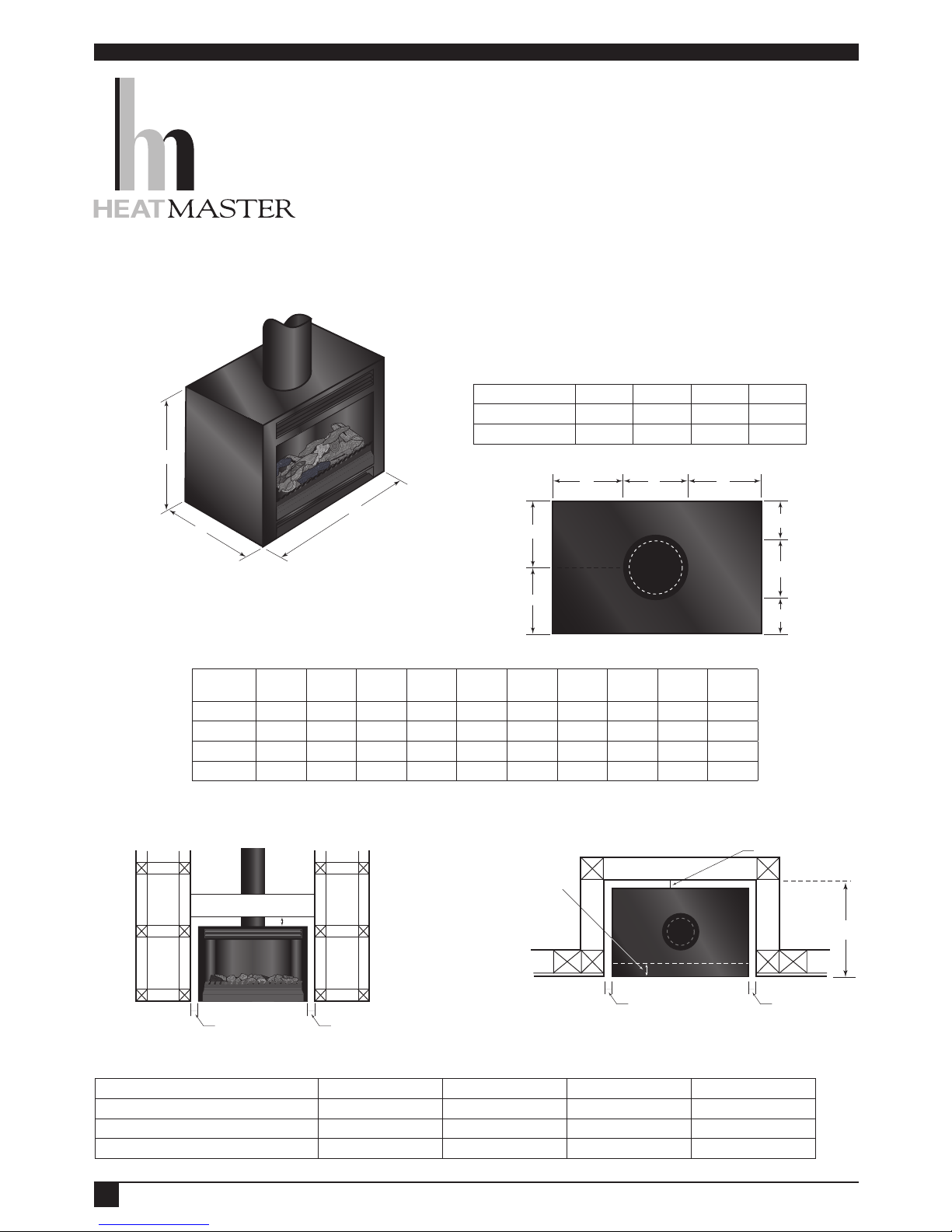
The Heatmaster open Gas fireplace system comes as a fully self-contained
fireplace kit. The firebox, gas kit, flues and gas cowl are the basic components
(Fig 1A). When installing your Heatmaster Gas fireplace please be sure to read
the following carefully and to comply with all clearances. Full specifications
are available upon request. Ensure that the gas connection is carried out by an
authorized person in accordance with local gas fitting regulations.
Fig 1B - Min. Framing Dimensions on Non-combustible floor
Fig 1A - Dimensions
Fig 1A - Flue System sizes and Specifications
Fig 1B
Fig 1A
Model No A450 A650 A750 A900
Inner Flue
150mm 180mm 200mm 200mm
Outer Flue
200mm 230mm 250mm 250mm
Model NoA B C D E F G H J K
A450
595mm 395mm 670mm 195mm 205mm 195mm 90mm 100mm 195mm 200mm
A650
840mm 470mm 680mm 315mm 205mm 315mm 155mm 110mm 255mm 215mm
A750
910mm 495mm 680mm 325mm 260mm 325mm 140mm 90mm 270mm 225mm
A900
1060mm 565mm 740mm 400mm 260mm 400mm 180mm 125mm 315mm 250mm
Model No A450 A650 A750 A900
Height from non combustible floor 695mm 705mm 705mm 765mm
Width
645mm 890mm 960mm 1110mm
Depth “C”
430mm 505mm 530mm 600mm
If installing onto combustible material, Heatmaster recommend 10mm cement sheeting underneath unit. Please take this into account when framing.
Page 3
STEP 1
STEP 2
STEP 3
Tiled Floor Protector
(Do not block air intake
at bottom of healer)
*Ensure that the gas
connection is done
by a licenced gas fitter.
Gas Kit
Non combustible
decorative
front cover
Selected lining
A
B
Power cord
3
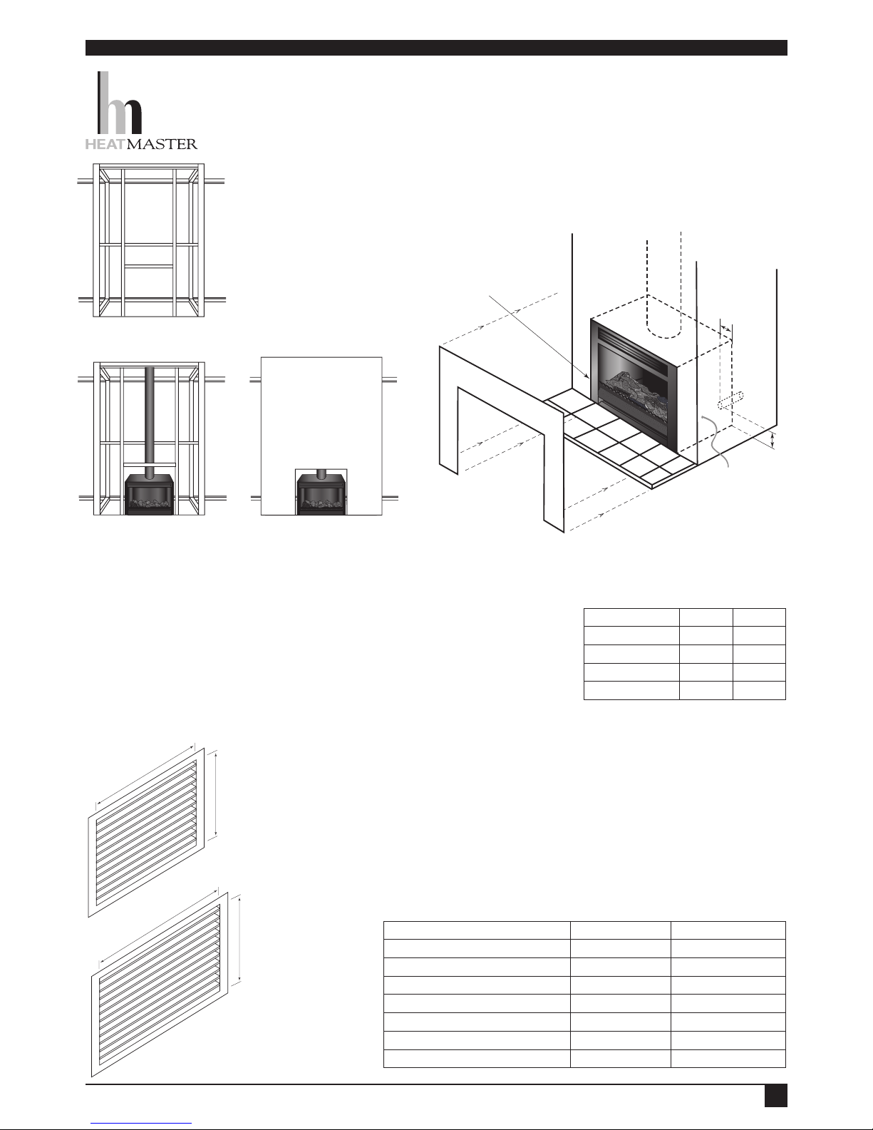
Fig 2A - Finishing your Heatmaster intallation
Step two.
Install selected insulated "A series" Heatmaster unit along
with flues (see Flue detail diagram fig 3A). Insert gas unit
using a qualified Gas Plumber. (For full gas specifications
read the Gas Kit Owners Manual)
Step three.
Enclose framing with plasterboard/gyprock or timber paneling,
ensuring approved clearances are maintained.
Step four.
Select one of our many finishing options. A wide range of stone,
marble, cast iron or steel fascias and mantelpieces are available.
Model LPG Natural Gas
450 Gas Coal / Log unit
23 MJ/Hr 28 MJ/Hr
650 Gas Coal / Log unit
31 MJ/Hr 37 MJ/Hr
750 Gas Coal / Log unit
31 MJ/Hr 37 MJ/Hr
900 Gas Coal / Log unit
36 MJ/Hr 39 MJ/Hr
650 Gas Log unit
40 MJ/Hr 48 MJ/Hr
750 Gas Log unit
40 MJ/Hr 48 MJ/Hr
900 Gas Log unit
60 MJ/Hr 60 MJ/Hr
Step one.
After selecting your
Heatmaster unit and
installing your hearth,
erect frame work
with the appropriate
clearance (see timber
framing specification fig 1B).
(If using a mantelpiece
ensure that the overall width
of your chimney breast is an
adequate size).
Model No A B
A450 110mm 120mm
A650 95mm 145mm
A750 115mm 125mm
A900 135mm 130mm
Fig 2B - Heatmaster firebox gas pipe location
125mm
270mm
125mm
430mm
Fig 2C - Room Ventilation
Option A
Option B
Permanent ventilation is required. (As per standard AS561 - AG601 - 2000)
A cross sectional area of 40,000sq mm of effective ventilation is required.
Therefore, if using option A you require 2 vents where using option B only requires 1.
Installation of gas fireboxes
Fig 2D - Gas MJ Input for Heatmaster Gas Fires
Step by step installation
Page 4
25 mm clearance
Gas Cowl
Ventilation holes
in outer flue or
cowl
Ceiling void
ROOF
Flashing
Inner
flue
Outer
flue
Framing
50 mm on edge
25mm from
combustible
material
Front of
unit
2nd skin
sit on top
of box
25mm from
combustible
material
Cover clearance
with desired fascia
Spacers on
inside of outer
flue to ensure
25mm clearance
from inner flue to
outer flue
Min Flue
height
3.6 m
from top
of unit
Ceiling void
Inner Flue
Crimp end faces down
Ventilation Holes
Outer Flue
Crimp end faces up
Firebox
ROOF
Situation "B"
600 min
above roof
Silicon flashing
to ensure no water
can enter roof line
Situation "A"
600 min above
roof 3.6 m away
Situation "A" less that 3.6 Metres
Situation "B" greater than 3.6 Metres
4
Installation of gas fireboxes
Flue details
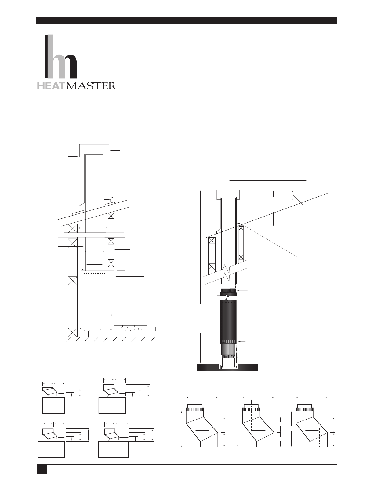
Fluing your Heatmaster Gas fireplace
The Heatmaster double skin flue kit, into timber and plaster must have
clearance of 25mm from any combustible material. Be sure the inner flue
crimped end faces down while the outer flue crimped end faces up. The first
and last length of flue must have ventilation holes, these cool the flue down
by allowing air to travel in between the two skins. Be sure to pop rivet (or
use self-tapers) and silicon flue lengths together along with the cowl. The
flue must protrude above the roofline by no less than 600mm with nothing
obstructing within 3600mm. (See diagram 3B)
Fig 3B - Flue Roof Clearance
Fig 3A - Flue installation
Fig 3C - Off sets and Clearances
200 300
105
450
260
100
230 300
110
650
300
390
100
250 300
150
750
340
430
100
250 330
150
900
340
430
130
420
190
190
200
470
A 650
380
190
190
200
470
A 450
440
190
200
200
480
A 750 and 900
 Loading...