

Page 1
EN • 1
ENGLISHFRANCAISNEDERLANDSESPAÑOLITALIANODEUTSCH
664Y2800.B
Installation, Operating and
Servicing Instructions
Page 2

EN • 2
ENGLISHFRANCAISNEDERLANDSESPAÑOLITALIANODEUTSCH
664Y2800.B
WARNINGS 3
Who should read these instructions 3
Symbols 3
Recommendations 3
Applicable standards 3
Warnings 3
INTRODUCTION 4
Totally condensing 4
Operating mode 4
Description of the specifications 6
Production of hot water 6
Frost protection 6
USERS GUIDE 7
Direction for use 7
Settings parameters 7
TECHNICAL CHARACTERISTICS 8
Natural gas categories 9
Propane categories 9
Domestic hot water features 9
ELECTRICAL CONNECTION 10
Wiring diagram 10
INSTALLATION INSTRUCTIONS 11
Dimensions 11
Hydraulic connections 11
Boiler room 11
INSTALLATION 12
Connection to the chimney 12
Connection to the gas 13
Domestic hot water connection 13
Heating connections 14
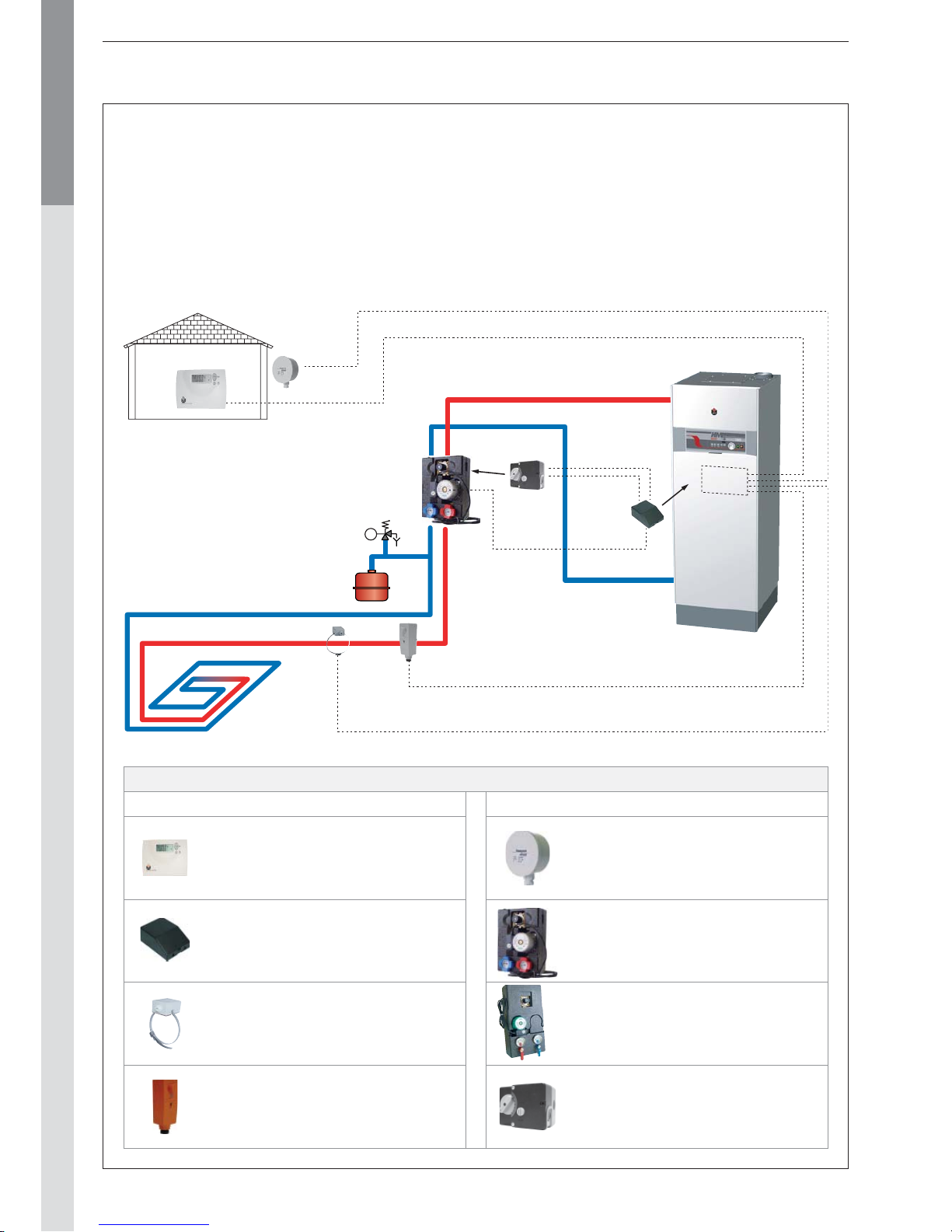
Installation of a single high temperature circuit with room thermostat ACV 15 control 15
Installation of a weather depending heating circuit high or low temperature 16
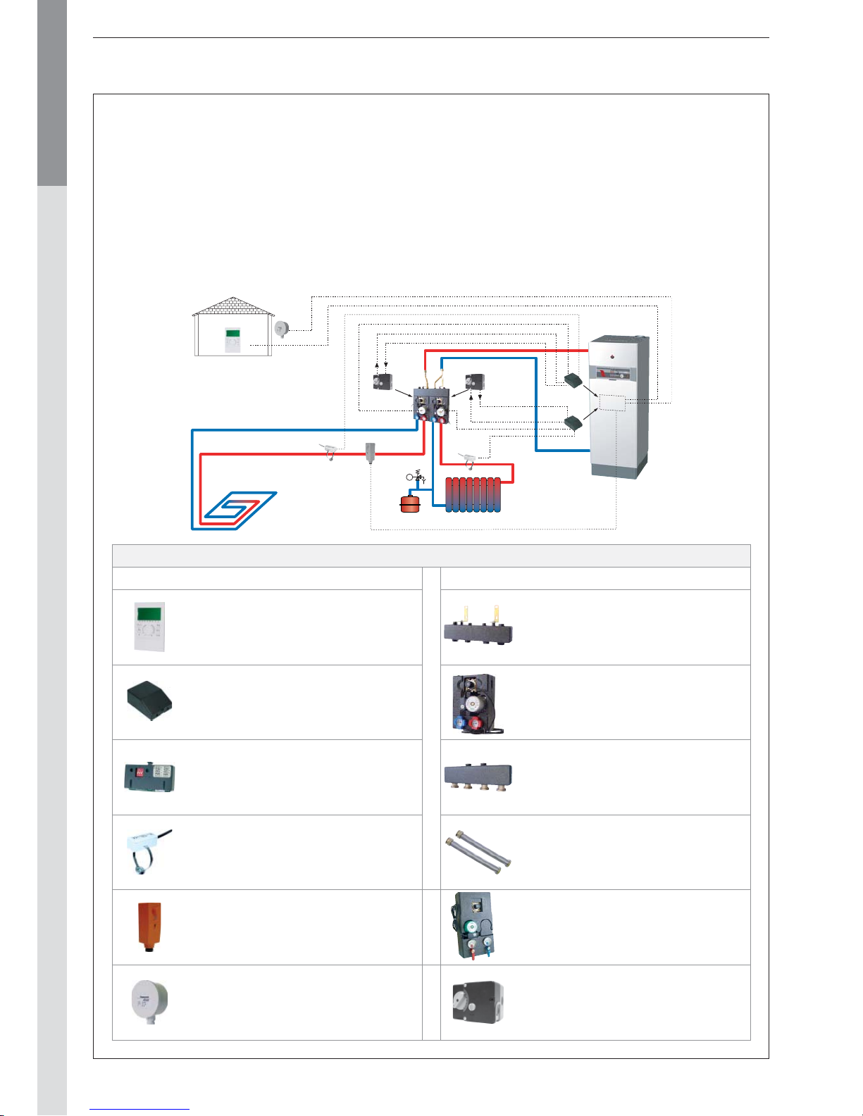
Installation of two heating circuit controlled by control unit and ZMC-1 module 18
COMMISSIONING AND MAINTENANCE 20
Commissioning the system 20
Inspection and maitenance 20
Temperature sensor resistance tables 20
Disassembling the burner 21
Disassembling and checking the electrode 21
Cleaning the heat exchanger 21
MCBA PARAMETERS FOR THE SPECIALIST 22
Standby mode 22
Setting the MCBA parameters 23
Request for information on the installation 24
Entering the code 24
MCBA parameters with code restricted access 25
Communication mode 28
Error mode 28
Safety stop [error mode] 29
INDEX
Page 3
EN • 3
ENGLISHFRANCAISNEDERLANDSESPAÑOLITALIANODEUTSCH
664Y2800.B
WHO SHOULD READ THESE INSTRUCTIONS
These instructions should be read by:
- the specifying engineer
- the installer
- the user
- the service engineer
SYMBOLS
The following symbols are used in this manual:
• The parts may only be replaced by genuine factory parts. You
will find a list of the spare parts and their ACV reference
number at the end of this document.
• The burners are preset in our factory for use with natural
gas
[equivalent to G20].
• Specific regulation applicable in Belgium:
The CO2 level, the air and gas flows and the gas / air ratio
are factory set . Any field adjustments of those settings is
not allowed in Belgium.
• It is important to switch the boiler off before carrying out
any work.
• There are no user accessible parts inside the boiler casing.
APPLICABLE STANDARDS
The appliances carry the CE mark in accordance with the
standards in force in the various countries (European Directives
92/42/EC “Efficiency”, 90/396/EC “Gas appliances”). They
also carry the “HR-TOP” label (Gas condensation boilers).
WARNINGS
IF YOU SMELL GAS:
- Immediately isolate the gas supply.
- Open windows and doors to ventilate the area.
- Do not use any electrical appliances and do not operate any
switches.
- Immediately notify your gas supplier and/or your installer.
This documentation is part of the information delivered with the
appliance and must be given to the user and stored in a safe
place!
An approved installer must carry out the assembly, commissioning,
maintenance and repair of the system, in accordance with current
standards in force.
ACV shall not accept any responsibility for damage caused by
non-compliant location of the system or by use of the parts or
connections not approved by ACV for this application.
The manufacturer reserves the right to change the
technical characteristics and specification of its
products without notice.
The availability of some versions and their accessories
is market dependant.
WARNINGS
RECOMMENDATIONS
• Please, carefully read this manual before installing and
commissioning the boiler.
• It is prohibited to carry out any modifications to the inside of
the appliance without the manufacturer’s prior and written
agreement.
• The product must be installed and serviced by trained
engineers, in compliance with current standards.
• Any failure to follow instructions relating to tests and test
procedures may result in personal injury or risks of pollution.
• To guarantee safe and correct operation of the appliance, it
is important to have it serviced and maintained every year by
an approved installer or maintenance company.
• In case of anomaly, please call your service engineer.
• Despite the strict quality standards imposed by ACV during
the manufacture, inspection and transport of its appliances,
you might notice some errors. Please report immediately any
fault to your approved installer. Remember to note the fault
code displayed on the screen.
Risk of scalding
Essential instruction for
the safety of persons
and the environment.
Danger of electrocution.
Essential instruction for
the correct operation of
the installation.
Page 4
EN • 4
ENGLISHFRANCAISNEDERLANDSESPAÑOLITALIANODEUTSCH
664Y2800.B
TOTALLY CONDENSING :
The HeatMaster
®
TC combines the
unique ACV Tank-in-Tank concept with
a dual primary circuit resulting in
exceptional performance from a totally
condensing combination boiler.
Tank-in-Tank technology
ACV’s advanced implementation of thermal storage technology is
tried and tested and is remarkably simple, efficient and reliable.
At the heart of the HeatMaster® TC is a stainless steel tank
through which the flue tubes pass.
This is surrounded by a mild steel shell containing the primary
water, which extends down to the combustion chamber and even
around the flue tubes. The burner fires onto the primary water
which indirectly heats the stainless steel tank containing the hot
water. As with all Tank-in-Tanks, this is corrugated over its full
height and is suspended in the HeatMaster® TC by its hot and
cold water connections.
The area of the heat transfer surface is therefore much greater
than that of standard direct fired water heaters. A much larger
heat transfer surface means that Tank-in-Tank units recover much
faster than any other kind of hot water storage device - and keeps
boiler cycling to a minimum. The high storage temperature within
the inner tank also results in exceptional hot water outputs.
Dual primary circuit technology
The HeatMaster® TC primary circuit is split into two sections - a
high temperature upper circuit and a low temperature lower circuit,
divided by a separation plate. The hot water storage tank is located
in the upper circuit which always operates at a temperature of
between 60°C and 90°C. This is ideal for hot water production as
it maintains the stored water at constantly high temperatures,
eliminating bacterial formation such as Legionellae, as well as
resulting in high volume hot water production.
The down-firing flue tubes pass through the upper circuit, through
the separation plate and into the lower circuit. The primary water
here operates at a temperature typically between 30°C and 60°C
for heating (dependent on the heating return temperature), perfect
for condensing when working in heating mode.
Dual coil technology
During hot water mode, the bottom circuit operates at a much
lower temperature, typically 5°C to 20°C depending on the
cold water inlet temperature. The incoming cold water enters
the lower primary circuit via an indirect water preheater. As
this preheater is wrapped around the lower flue tubes of the
combustion chamber, it is able to absorb the remaining heat
from the flue gases. The result is that during hot water mode the
HeatMaster® TC totally condenses whether on full or part-load.
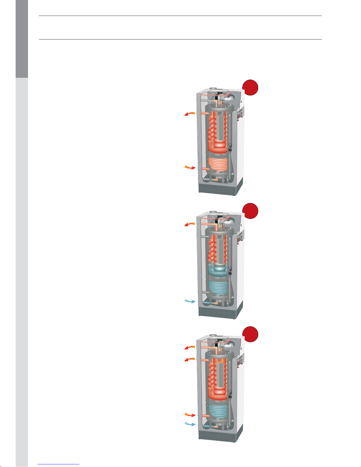
INTRODUCTION
Heating
The heating return
enters the lower circuit
of the boiler, which allows
the boiler to operate
in condensing mode.
The upper circuit of the
HeatMaster® TC is kept
at a consistently high
temperature due to the
internal shunt pump which
ensures that the primary
water circulates around
the heat exchanger flue
tubes.
Heating and
hot water
Once up to temperature,
the HeatMaster® TC is
capable of producing
heating and hot water
simultaneously.
Hot water
With the upper circuit
maintained at high
temperature, the
HeatMaster® TC is always
ready to supply hot water
on demand.
The cold water enters
through the indirect water
preheater at the base of
the heat exchanger and is
preheated before entering
the hot water tank. The low
temperature of the bottom
circuit results in continuous
condensation of the flue
gases in hot water mode.
Operating modes
In both heating and hot water modes, the premix
gas burner fully modulates the power to match
the system demand.
1
3
2
Page 5
EN • 5
ENGLISHFRANCAISNEDERLANDSESPAÑOLITALIANODEUTSCH
664Y2800.B
INTRODUCTION
4
6
8
1
5
2
3
9
11
16
17
12
14
13
15
18
7
10
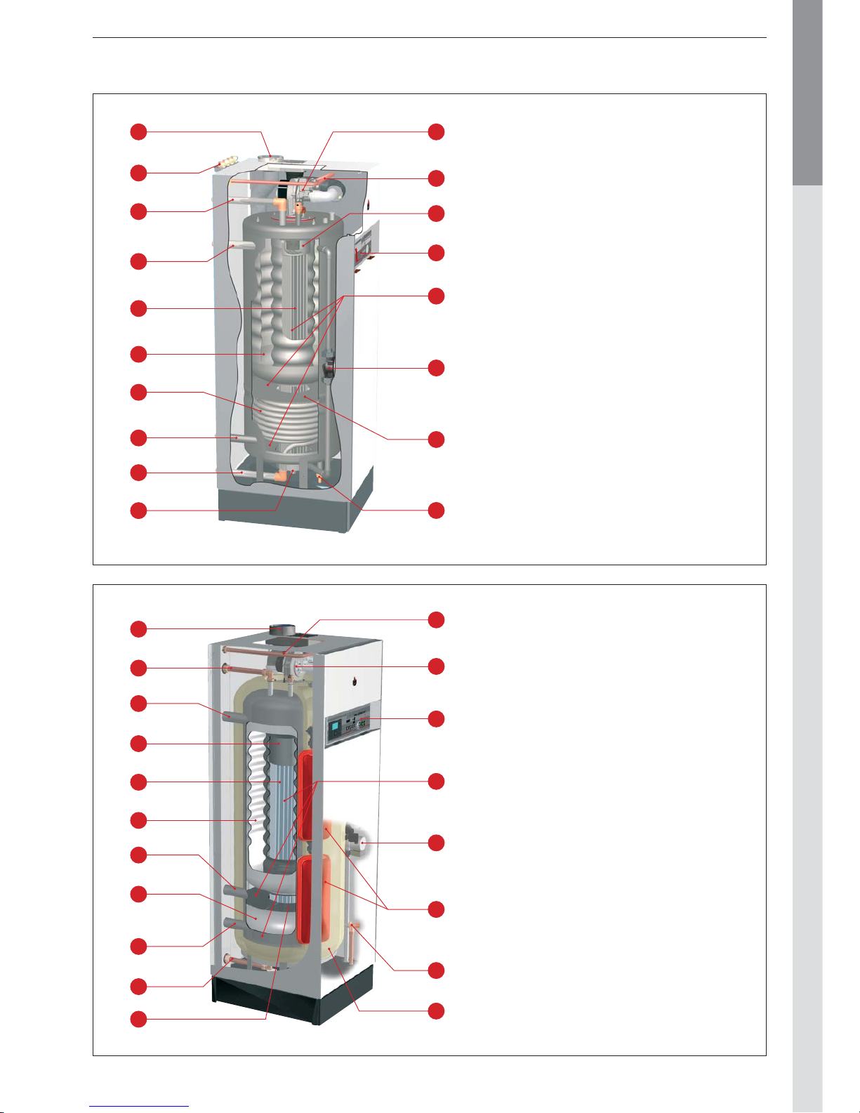
HeatMaster® 35 TC
1. Flue connection concentric Ø 80/125 mm convertible to
parallel connection 80/80 mm
2. Connection frame [optional]
3. Domestic hot water outlet
4. Heating flow
5. Stainless steel heat exchanger
6. Stainless steel Tank-in-Tank hot water store
7. Stainless steel cold water inlet coil
8. Heating return
9. Cold water inlet
10. Condenstrap
11. Modulating premix gas burner
12. Gas connection
13. Combustion chamber
14. Control panel
15. Primary heating circuit
16. Boiler shunt pump
17. Separation plate
18. Drain cock
HeatMaster® 85 TC
1. Flue connection concentric Ø 100/150 mm convertible to
parallel connection Ø 100/100 mm
2. Domestic hot water outlet
3. Heating flow
4. Combustion chamber
5. Stainless steel heat exchanger
6. Stainless steel Tank-in-Tank hot water store
7. Auxiliary tank primary return
8. Indirect water preheater
9. Heating return
10. Cold water inlet
11. Separation plate
12. Gas connection
13. Modulating premix gas burner
14. Control panel
15. Primary heating circuit
16. Boiler shunt pump
17. Primary expansion vessel (2x)
18. Primary safety valve (3 bar)
19. Polyurethane foam insulation
5
7
9
1
6
2
3
10
12
16
13
14
15
19
8
4
17
18
11
Page 6

EN • 6
ENGLISHFRANCAISNEDERLANDSESPAÑOLITALIANODEUTSCH
664Y2800.B
DESCRIPTION OF THE SPECIFICATIONS
The HeatMaster® TC is an hot water producer combined in
a condensing boiler in accordance to the Belgium "HR-Top"
standard. The boiler is certified compliant with "CE" standards as
a connected appliance C13(x) - C33(x) - C43(x) - C53 - C83(x), but
it can also be connected as an open appliance in category B23.
Lining
The boiler is protected by a steel lining that first of all undergoes a
degreasing and phosphation process before being lacquered and
heated at 220°C. The inside of this lining is coated with a layer of
thermal and acoustic insulation, reducing losses to a minimum.
Heat exchanger
The core of the HeatMaster® TC features a new stainless steel
heat exchanger. This piece of technology represents the fruit of
exhaustive research and intensive laboratory testing. It reflects
ACV’s eighty years of experience in using stainless steel for
heating and hot water functions. The particular geometry of the
exchanger pipes is calculated to obtain a very large Reynolds
number throughout its cycles.
The HeatMaster® TC achieves an exceptional output that remains
stable throughout the boiler’s life, given that it causes no oxidation
on the exchanger, which is manufactured entirely from quality
steel.
Burner
ACV uses its BG 2000-M burner for the HeatMaster® TC: this
is an air/gas premix burner providing safe and silent operation
while limiting emissions (NOx and CO) to an incredibly low level.
Although the ACV BG 2000-M boiler is very modern, it uses
proven technology and is manufactured from standard spare
parts that are easily available on the market.
Temperature regulation
The basic version of the HeatMaster® TC is fitted with a
microprocessor controlled regulator (MCBA) which takes over
both the safety functions (ignition, monitoring the flame, limiting
the temperature, etc.) and control of the boiler temperature.
This MCBA also includes a weather-dependent regulator. All you
need to do is connect the outdoor temperature sensor available
as an option to the device. However, this regulator can also
operate with a standard on/off room thermostat In addition,
with the combination of a weather -dependent regulator and a
room thermostat, you can control the temperatures based on
the weather with compensation for the indoor temperature.
There are four user adjustable parameters. By entering a
special maintenance code, qualified ins tallers can access
several other parameters to adapt the boiler to special
requirements. In principle, these parameters are factory set
for all normal applications.
PRODUCTION OF HOT WATER
In addition to its exceptional hot water performances, the ACV
Tank-in-Tank concept provides the follwoing advantages :
- A solution for scale deposits: thanks to the specially designed
corrugations, the hot water tank expands and contracts during
the heating cycle, preventing the formation of scale.
- A guarantee against the risk of Legionnellae Disease and
bacteria: the hot water tank is fully immersed in the primary
circuit and the hot water is constantly kept at a temperature
above 60°C.
- Exceptional resistance against corrosion and aggression:
provided by the stainless steel.
FROST PROTECTION
The boiler is equipped with an integrated frost protection: as soon
as the boiler temperature drops below 7°C, the system activates
the central heating pump. As soon as the NTC1 flow temperature
drops below 3°C, the system automatically ignites the burner until
the temperature rises above 10°C. The pump continues to run
for about 10 minutes.
If an outdoor temperature sensor is connected to the system,
the pump is activated as soon as the outside temperature drops
below the specified threshold.
To provide efficient protection for the whole system against frost,
all the valves on the radiators and the convectors should be
completely open.
INTRODUCTION
Page 7
EN • 7
ENGLISHFRANCAISNEDERLANDSESPAÑOLITALIANODEUTSCH
664Y2800.B
DIRECTIONS FOR USE
Your system must be checked once a year by an approved
installer or maintenance company.
Starting the burner
During operation, the burner starts automatically as soon as
the boiler temperature drops under the required set point and
it stops as soon as the boiler reaches that temperature.
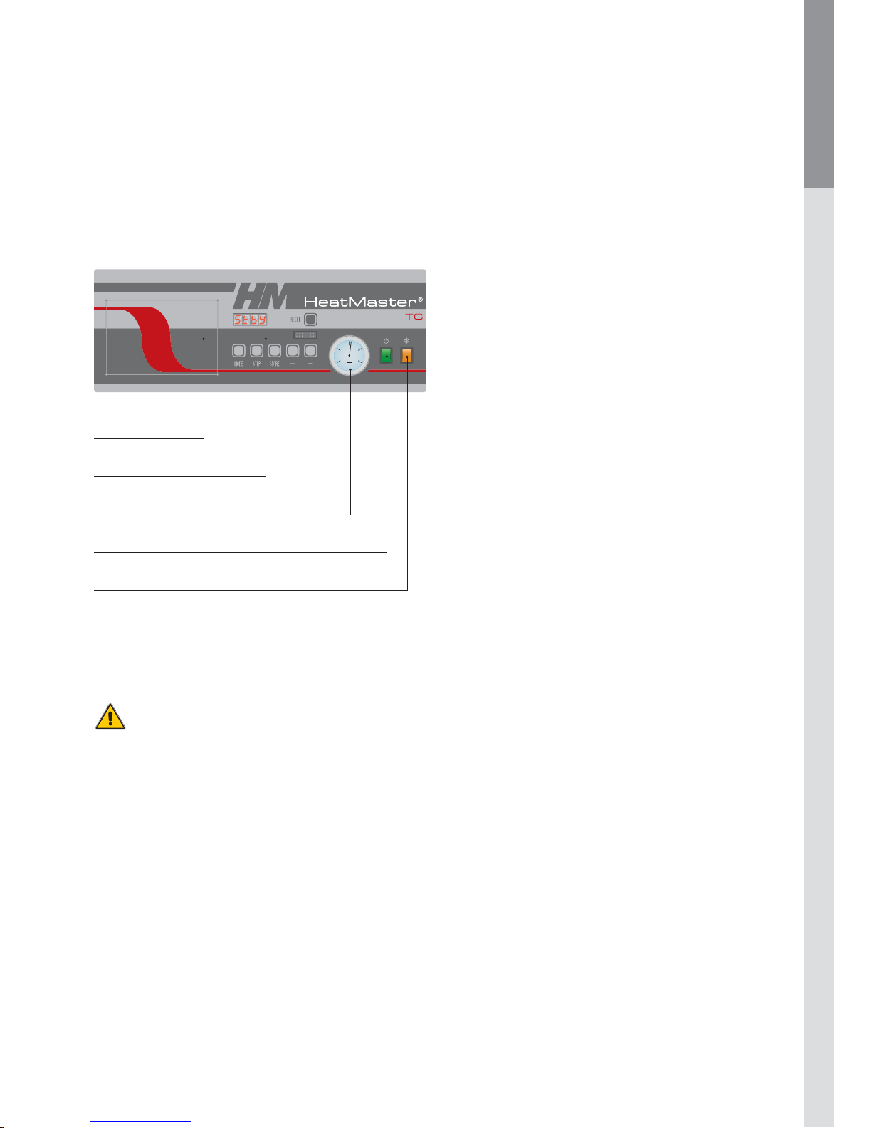
Control panel
SETTINGS PARAMETERS
Setting the domestic hot water temperature:
(Hot water temperature)
- Press Mode: The screen displays PARA.
- Press Step: the first character is 1 and the last t wo characters
give the current hot water temperature setting.
- To change this temperature, press + or - until the last two
digits show the desired temperature value.
- Press Store to save the new temperature setting.
- Press Mode twice to return to Pilot mode (normal operating
mode).
Enabling or disabling the hot water heating mode:
(hot water)
- Press Mode: The screen displays PARA.
- Press Step twice: the first charact er is 2 and the last two
characters give the current setting:
00 = disabled; 01 = enabled.
- To change this parameter, press + or - until the screen displays
the desired value:
00 = disabled; 01 = enabled.
- Press Store to save.
- Press Mode twice to return to Pilot mode (normal operating
mode).
Enabling or disabling Central Heating mode:
(heating)
- Press Mode: The screen displays PARA.
- Press Step three times: the firs t character is 3 and the last
two characters give the current setting:
00 = disabled; 01 = enabled.
- To change this parameter, press + or - until the screen displays
the desired value:
00 = disabled; 01 = enabled.
- Press Store to save.
- Press Mode twice to return to Pilot mode (normal operating
mode).
Setting the central heating temperature:
(maximum temperature for the heating circuit)
- Press Mode: The screen displays PARA.
- Press Step four times: the first character is 4 and the last
two characters give the current central heating temperature
setting.
- To change this temperature, press + or - until the last two
digits show the desired temperature value.
- Press Store to save the new temperature setting.
- Press Mode twice to return to Pilot mode (normal operating
mode).
Fault:
The temperature setting for the appliance and the safety
functions for its various parts are continuously monit ored by
a regulator controlled by a microprocessor (the MCBA). In the
event of a fault, this MCBA disables the appliance and displays
an error code: the screen flashes displaying E as the first
character, followed by the error code.
To reset the appliance:
- Press "Reset" on the screen.
- Contact your inst aller of the fault happens again.
USERS GUIDE
Heating system
The central heating circuit must be pressurized (see in the
chapter “Installation” how to define the system pressure).
The pressure indicator is located on the right-hand side of the
display.
If your system needs to be refilled more than twice
a year, please contact your installer.
The CH pressure must be a minimum of 1 bar and mus t be
checked by the end user on a regular basis. If the pressure
drops under 0.5 bar, the integrated water pressure switch
blocks the appliance until the pressure in the system returns to
a level above 0.8 bar. The connection for a fill valve is provided
underneath the appliance. The installer can also fit the system
with a separate valve. Make sure that the appliance is powered
off when filling the system. To do this, toggle the Star t/Stop
switch located on the left of the screen to Off. (see the Control
panel).
For more information, please ask your installer when the system
is delivered.
A safety valve is provided at the underneath of the appliance.
If the system pressure exceeds 3 bars, this valve opens and
drains the water from the system. In this case, please contact
your installer.
bar
2
1O3
4
MCBA display
Pressure gauge
ON/OFF switch
Summer/Winter switch
Pre-cut for an optional
Control Unit controller
Page 8

EN • 8
ENGLISHFRANCAISNEDERLANDSESPAÑOLITALIANODEUTSCH
664Y2800.B
TECHNICAL CHARACTERISTICS
HeatMaster
®
35 TC
HeatMaster
®
85 TC
Central heating Natural gas Propane Natural gas Propane
Max. Input 80/60°C
kW
34,9 30,6 85,0 [92,0] 85,0 [92,0]
Min. Input 80/60°C
kW
10,0 10,0 17,2 17,2
Max. output 80/60°C
kW
34,1 29,9 82,5 82,5
Min. output 80/60°C
kW
9,8 9,8 16,7 16,7
Effi ciency 30% load [EN677]
%
108,5 108,5 107,0 107,0
Effi ciency domestic hot water mode [Δt = 30°C]
%
105,9 105,9 105,0 105,0
Flue gases
CO emissions max. / min. Input
mg/kWh
70 / 6 105 / 17 70 80
NOx emissions max. / min. Input
mg/kWh
59 / 29 72 / 31 70 / 30 85 / 40
NOx classifi cation [EN483] 5 5 5 5
Flue gas temperature — max. Input 80/60°C
°C
60 60 65 65
Flue gas temperature — max. Input 50/30°C
°C
32 32 35 35
Mass fl ow rate of combustion products
kg/h
55 46,5 137 [148] 134 [145]
Flue gas pipe - Max. pressure drop
Pa
130 130 150 150
Concentric fl ue gas channel maximum length Ø 80 / 125 mm
m
20 20 20 20
Gas G20 / G25 G31
Category [varies by country]
I 2E[S]B — I 2Er
I 2L — I 2E
I 2ELL — I 2H
I 2HS
I 3P
I 3+
I 3B
I 2E[R]B — I 2Er
I 2L — I 2E
I 2ELL — I 2H
I 2HS
I 3P
I 3+
I 3B
Gas pressure
mbar
20 / 25 30 / 37 / 50 20 / 25 30 / 37 / 50
G20 gas fl ow rate
m
3
/h
3,7 — 8,99 [9,73] —
G25 gas fl ow rate
m
3
/h
4,3 — 10,46 [11,32] —
G31 gas fl ow rate
m
3
/h
— 1,25 — 3,48 [3,76]
CO
2
max. Input
% CO
2
9,4 10,5 9,3 11,0
CO
2
min. Input
% CO
2
9,0 10,1 8,9 10,6
Hydraulic parameters
Max. operating temperature
°C
90 90 90 90
Total capacity
L
189 189 315 315
Heating circuit capacity
L
108,5 108,5 125 125
Maximum operating pressure central heating
bar
3333
Heat exchanger pressure drop [ΔT = 20°C]
mbar
30 30 200 200
Electrical connection
Class
IP
30 30 30 30
Supply voltage
V/Hz
230/50 230/50 230/50 230/50
Maximum absorbed electrical power
A
0,8 0,8 1,0 1,0
Weight empty kg 174 174 284 284
[…] = Domestic hot water mode
Page 9
EN • 9
ENGLISHFRANCAISNEDERLANDSESPAÑOLITALIANODEUTSCH
664Y2800.B
TECHNICAL CHARACTERISTICS
Natural gas categories
BE FR NL LU DE
AT - CH - CZ - DK - ES - IT
FI - UK - IE - PT - SE - GR
HU
I 2E(S)B
[G20] 20 mbar – [G25] 25 mbar
I 2E(R)B *
[G20] 20 mbar – [G25] 25 mbar
I 2Er
[G20] 20 mbar – [G25] 25 mbar
I 2L
[G25] 25 mbar
I 2E
[G20] 20 mbar
I 2ELL
[G20] 20 mbar – [G25] 20 mbar
I 2H
[G20] 20 mbar
I 2HS
[G20] 25 mbar
(*) HeatMaster® 85 TC
Propane categories
DK - NL
NO - IT
BE - CH - ES
FR - UK - IE
PT - FI - SE
IT - GR
AT - CH
CZ - ES
NL - DE
LU - HU
BE - CH
ES - FR
UK - IE
IT - PT
CZ - DK - ES
FI - FR - UK
IE - IT - NL
NO - PT - SE
AT - CH
CZ - DE
FR
I 3P
[G31] 30 mbar
I 3P
[G31] 37 mbar
I 3P
[G31] 50 mbar
I 3+
[G30 + G31] 28 / 30 / 37 mbar
I 3B
[G30] 28 / 30 mbar
I 3B
[G30] 50 mbar
DOMESTIC HOT WATER FEATURES
HeatMaster
®
35 TC
HeatMaster
®
85 TC
Operating conditions at 80°C
Peak fl ow at 40°C [ΔT = 30°C]
L/10’
419 850
Peak fl ow at 40°C [ΔT = 30°C]
L/60’
1312 3177
Constant fl ow at 40°C [ΔT = 30°C]
L/h
1057 2793
Peak fl ow at 45°C [ΔT = 35°C]
L/10’
381 722
Peak fl ow at 45°C [ΔT = 35°C]
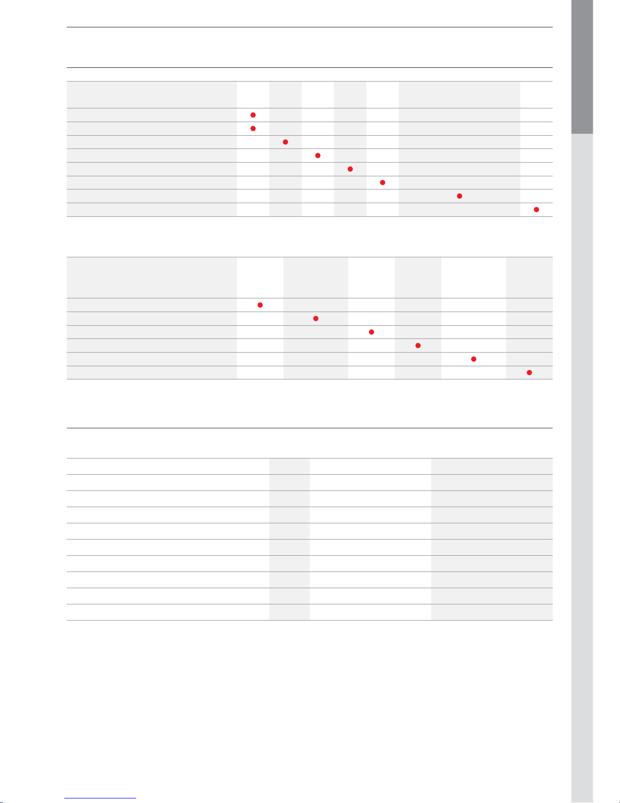
L/60’
1080 2717
Constant fl ow at 45°C [ΔT = 35°C]
L/h
898 2394
Peak fl ow at 60°C [ΔT = 50°C]
L/10’
224 459
Peak fl ow at 60°C [ΔT = 50°C]
L/60’
692 1778
Constant fl ow at 60°C [ΔT = 50°C]
L/h
578 1583
Pre-heat time
minutes
37 35
Page 10
EN • 10
ENGLISHFRANCAISNEDERLANDSESPAÑOLITALIANODEUTSCH
664Y2800.B
ELECTRICAL CONNECTION
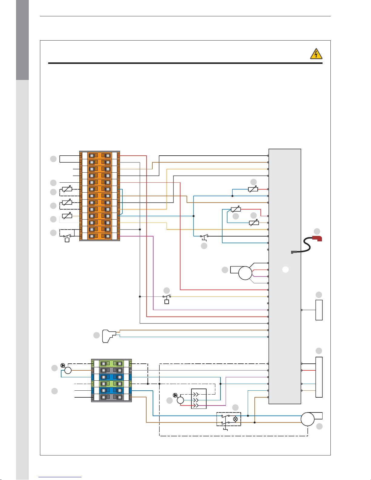
WIRING DIAGRAM : HeatMaster® TC
1. Power supply 230 V
2. ON/OFF switch
3. Boiler shunt pump
4. Heating pump (optional)
5. Gas valve rectifier
6. 230Volt - 24Volt transformer
7. MCBA
8. Display
9. Water pressure switch
10. Fan PWM control
11. Summer/Winter switch
12. NTC1 flow sensor
13. NTC2 return sensor
14. NTC5 flue gas temperature
15. Room thermostat (optional)
16. NTC3 domestic hot
17. NTC4 outdoor temperature (optional)
18. NTC6 second heating circuit flow sensor (optional)
19. Zero volt of 24V circuit.
20. Safety contact thermostat RAM (optional)
21. Ionisation and ignition cable
22. Burner power supply 230 V (only HeatMaster
®
85 TC]
B. Blue
Bk. Black
Br. Brown
G. Grey
Or. Orange
R. Red
V. Violet
W. White
Y/Gr. Yellow/Green
123 546
123 546
12345678910111213
12345678910111213
230V
Br
B
Br
B
M
P
t
BUS B
BUS A
X11.
X12.
Br
B
B
Br
B
R
Bk
V
W
Y/Gr
B
Br
B
Br
G
R
V
G
R
V
Or
OrG
R
W
V
R
Bk
B
BkBkB
Or
Br
R
RB
Br
B
RB
Br
Bk
Bk
Or
V
G
Or
B
W
Br
Bk
Br
R
Bk
Br
G
R
Br
B
Y/Gr Y/Gr
Y/Gr
B
W
L
N
PE
Y/Gr
B
Br
B
B
B
M
Y/Gr
L1
N
PE
X1.6
X1.5
X1.4
X1.3
X1.2
X7
X10.6
X10.7
X10.1
X10.3
X1.1
X2.12
X2.11
X2.10
X2.9
X2.8
X2.7
X2.6
X2.5
X2.4
X2.3
X2.2
X2.1
X3.6
X3.5
X3.4
X3.3
X3.2
X3.1
X4.3
X4.2
X4.1
X5.4
X5.3
X5.2
X5.1
1
2
3
4
5
6
8
9
7
1010
13
15
14
21
12
11
16
17
18
19
20
22
Page 11
EN • 11
ENGLISHFRANCAISNEDERLANDSESPAÑOLITALIANODEUTSCH
664Y2800.B
INSTALLATION INSTRUCTIONS
Min. 300 mm
Min. 25 mm Min. 25 mm
bar
2
1O3
4
BOILER ROOM
- Make sure that all air vents are unobstructed any times.
- Do not store any flammable products in the boiler room.
- Do not store any corrosive products, paint, solvents, salts,
chlorine products and other detergent products near the
appliance.
- If you smell gas, do not switch on any lights, turn off the
gas tap at the meter, ventilate the rooms and contact your
installer.
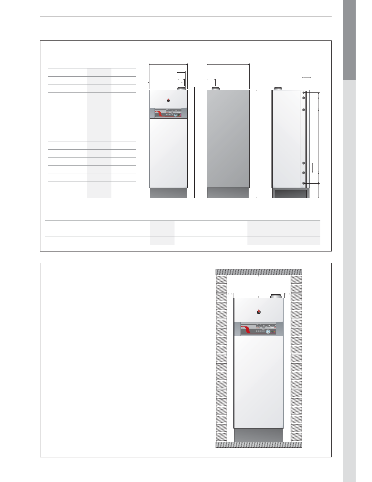
ACCESSIBILITY
The appliance must be positioned in such a way to be
accessible any time. In addition, the following distances
are required around the appliance.
DIMENSIONS
HM
35 TC
HM
85 TC
A mm 1720 2145
B mm 600 690
C mm 500 580
D mm 80 100
E mm 125 150
F mm 140 160
G mm 1700 2095
H mm 670 725
I mm 110 125
J mm 100 105
K mm 200 270
L mm 960 1210
M mm - 200
N mm 170 235
O mm 230 240
Weight empty (kg] 174 284
bar
2
1O3
4
A
B
C
D
E
G
H
F
O
N
L
K
J
I
M
HYDRAULIC CONNECTIONS HeatMaster® 35 TC HeatMaster® 85 TC
Heating connection [F] Ø 1" 1"1/2
Domestic hot water connection [M] Ø 1" 1"1/2
Gas connection [M] Ø 3/4" 3/4"
Page 12
EN • 12
ENGLISHFRANCAISNEDERLANDSESPAÑOLITALIANODEUTSCH
664Y2800.B
INSTALLATION
bar
2
1O3
4
1000 mm
1000 mm
2000 mm
2000 mm
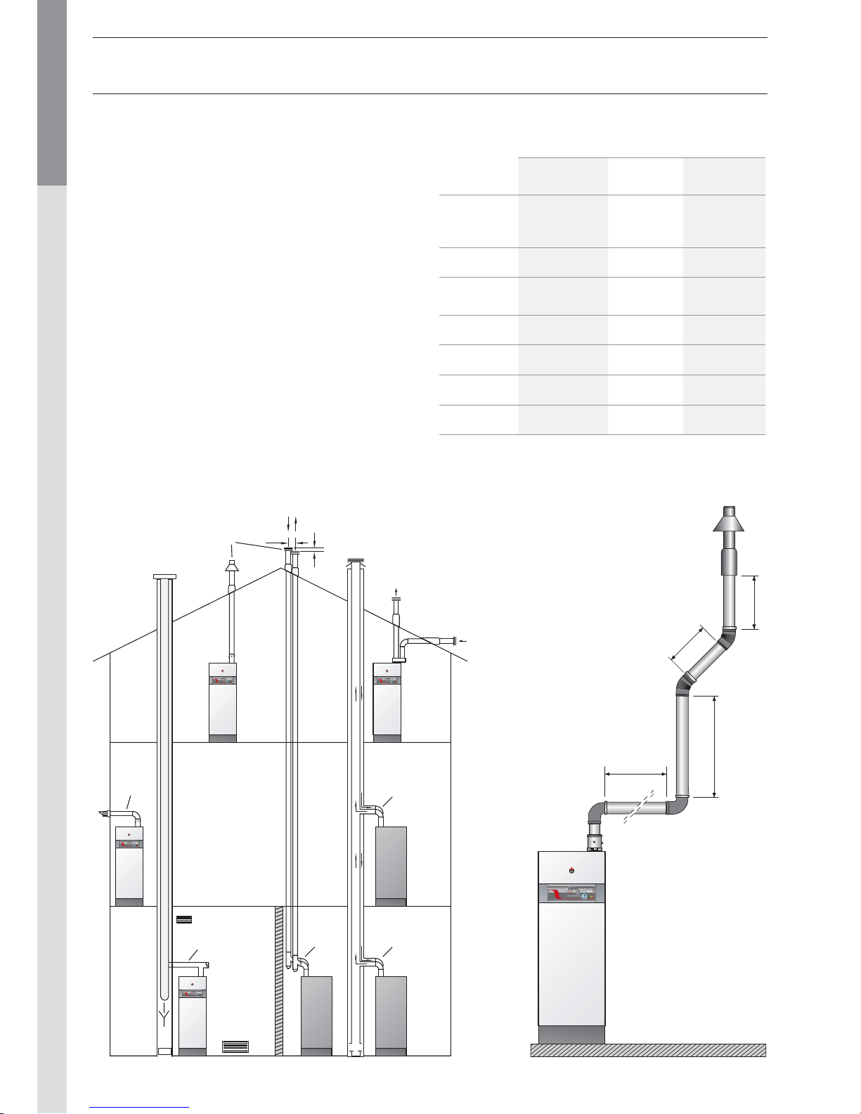
Sample calculation:
The diagram below consists
of the following parts: pipe with
monitoring section + 2 * 90°
pipe bends + 2 metres of
horizontal pipe + 2 * 45° pipe
bends + (2 + 1 + 1) metres of
vertical pipe and fall back +
discharge.
Therefore, the resistance of this
system is as follows:
2.5 + (2 x 6.0) + (2 x 5.0) +
(2 x 4.0) + (4 x 5.0) + 20
= 72.5 Pa.
This value is less
than the maximum
authorised resistance,
therefore the
installation is
compliant.
CONNECTION TO THE CHIMNEY
- The chimney connections must comply with the applicable
standards (in Belgium: NBN D51-003), the local energy
supplier’s instructions, the fire regulation and neighbourhood
good practices.
- The HeatMaster® TC has an inbuilt gas/air ratio regulator,
which makes it largely independent of the pressure drop in
the air intake and flue gas extraction system. However, the
maximum pressure drop for this system may not be exceeded,
or the pressure will diminish. Nevertheless, the gas/air ratio
regulator continuously guarantees optimum combustion with
very low emission levels.
- To avoid any condensate flow through the terminal, the
horizontal flue gas pipes must always be installed with a min.
slope of 5 mm per meter, upwards from the boiler side.
- There must be no obstruction or openings for any other
appliances within a radius of 0.5 metres around the flue
terminal of the HeatMaster® TC.
- The maximum flue resistance is 130 Pascal for the
HeatMaster® 35 TC and 150 Pascal for the HeatMaster® 85
TC. You can use the following table as the basis for calculating
this value: (please also refer to the specimen calculation presented
under the table).
C53
C33
150 min.
120
C13
B 23
C43
C43C33
bar
2
1O3
4
bar
2
1O3
4
bar
2
1O3
4
bar
2
1O3
4
Options for connection to the chimney
Table of flue resistance in Pascal
(1 Pascal = 0,01 mbar)
Pipe
concentric
Air inlet
separate
Air extraction
separate
HM
35 TC
Ø 80/125
mm
HM
85 TC
Ø 100/150
mm
HM
35 TC
Ø 80
mm
HM
85 TC
Ø 100
mm
HM
35 TC
Ø 80
mm
HM
85 TC
Ø 100
mm
1 m
straight pipe
5.0 13,5 1.5 4,1 2.0 5,5
Pipe with a
monitoring
section
2.5 6,8 — — 1.0 2,7
90° pipe bend
6.0 16,4 1.9 5,2 3.4 9,3
45° pipe bend
4.0 10,9 1.3 3,5 2.3 6,3
Vertical pipe
20.0 54,5 — — — —
Horizontal pipe
15.0 40,9 — — — —
This table is based on the equipment offered by ACV and cannot be applied
generally.
Page 13
EN • 13
ENGLISHFRANCAISNEDERLANDSESPAÑOLITALIANODEUTSCH
664Y2800.B
INSTALLATION
CONNECTION TO THE GAS
- The HeatMaster® TC is fitted with a Ø 3/4” male fitting
connec tor, on which you can connect the gas tap.
- The gas connection must comply with the applicable
regulations (e.g. NBN D51-003 in Belgium) in the country
of installation.
- Where there is a risk of dirt stemming from the network,
place a gas filt er upstream from the connection.
- Drain the gas pipe and check in minute detail that all the
boiler pipes, both inside and outside, are sealed.
- Check the gas pressure in the system.
Consult the technical characteristics.
- Check the gas pressure and consumption when
commissioning the appliance.
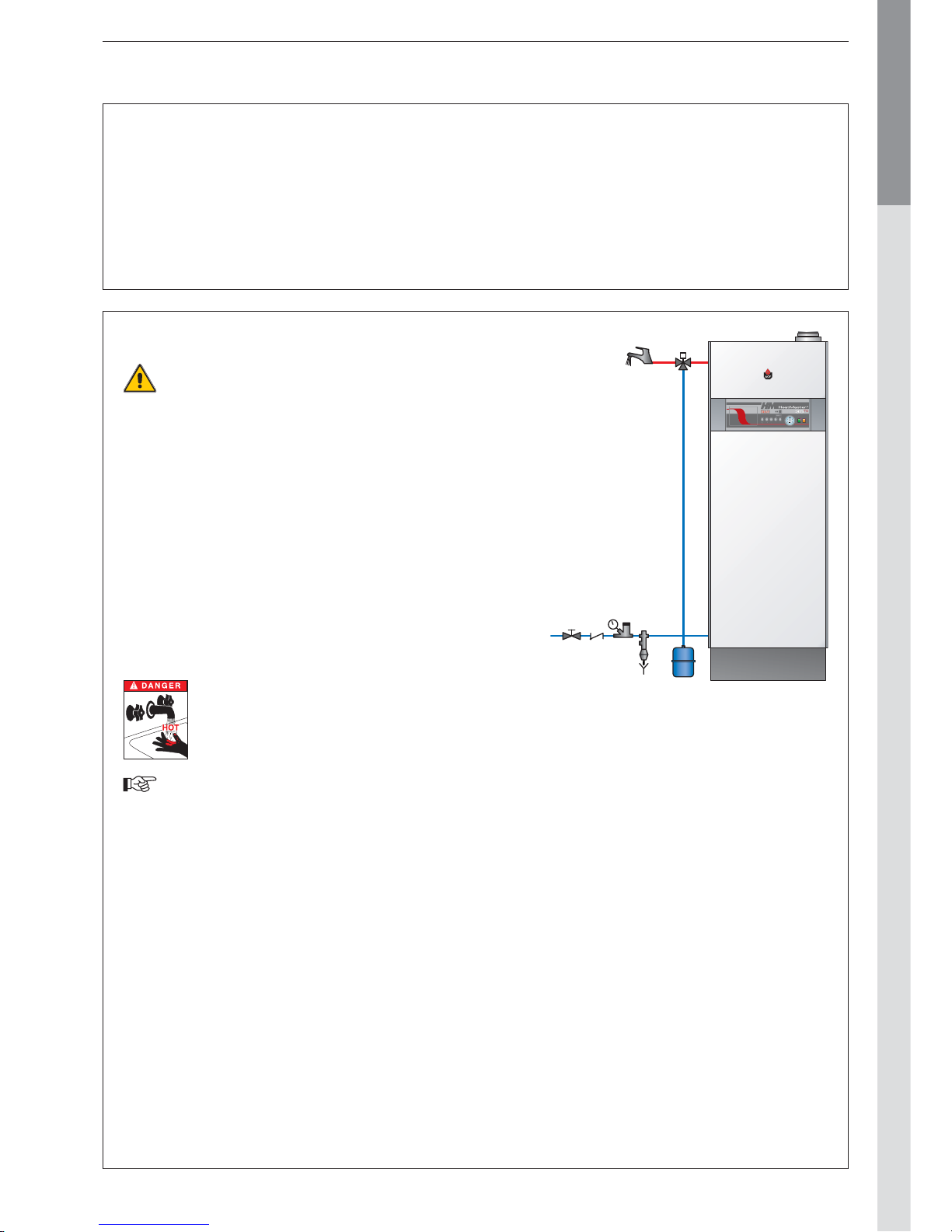
DOMESTIC HOT WATER CONNECTION
Before pressurising the central heating circuit
(primary) you should first pressurise the domestic
hot water tank (secondary) .
The HeatMaster® TC boiler can be connected direc tly on the
domestic hot water circuit.
Flush out the system before connecting the domestic hot
water part.
The installation must be fitted with an approved safety unit
with a 7-bar safety valve, a non-return valve and a shut-of f
valve.
During the heating process, the domestic hot water dilates
and the pressure increases. As soon as the pressure exceeds
the safety valve setting, the valve opens and discharges a
small quantity of water. Using a hot water expansion vessel
(2 litres at least) will prevent this phenomenon and reduce
water hammer effect.
The hot water output temperature may
reach temperatures in excess of 60°C, which
can cause burns. We therefore recommend
that that you install a the rmostatic mixer
immediately after installing the appliance.
If stop valves are used in the domestic hot water
system, they can cause pressure waves when
closed. Use devices designed to reduce water
hammer to avoid this phenomenon.
1. Cold water supply tap
2. Non-return valve
3. Pressure reducing valve
4. Safety group
5. Hot water expansion vessel
6. Thermostatic mixer
7. Drawoff tap
5
6
7
12
3
4
bar
2
1O3
4
Page 14
EN • 14
ENGLISHFRANCAISNEDERLANDSESPAÑOLITALIANODEUTSCH
664Y2800.B
HEATING CONNECTIONS
Recommendations
Before pressurising the central heating circuit
(primary) you should first pressurise the domestic
hot water tank (secondary) .
- The central heating system must be completely flushed
out wi th tap water before connecting the boiler.
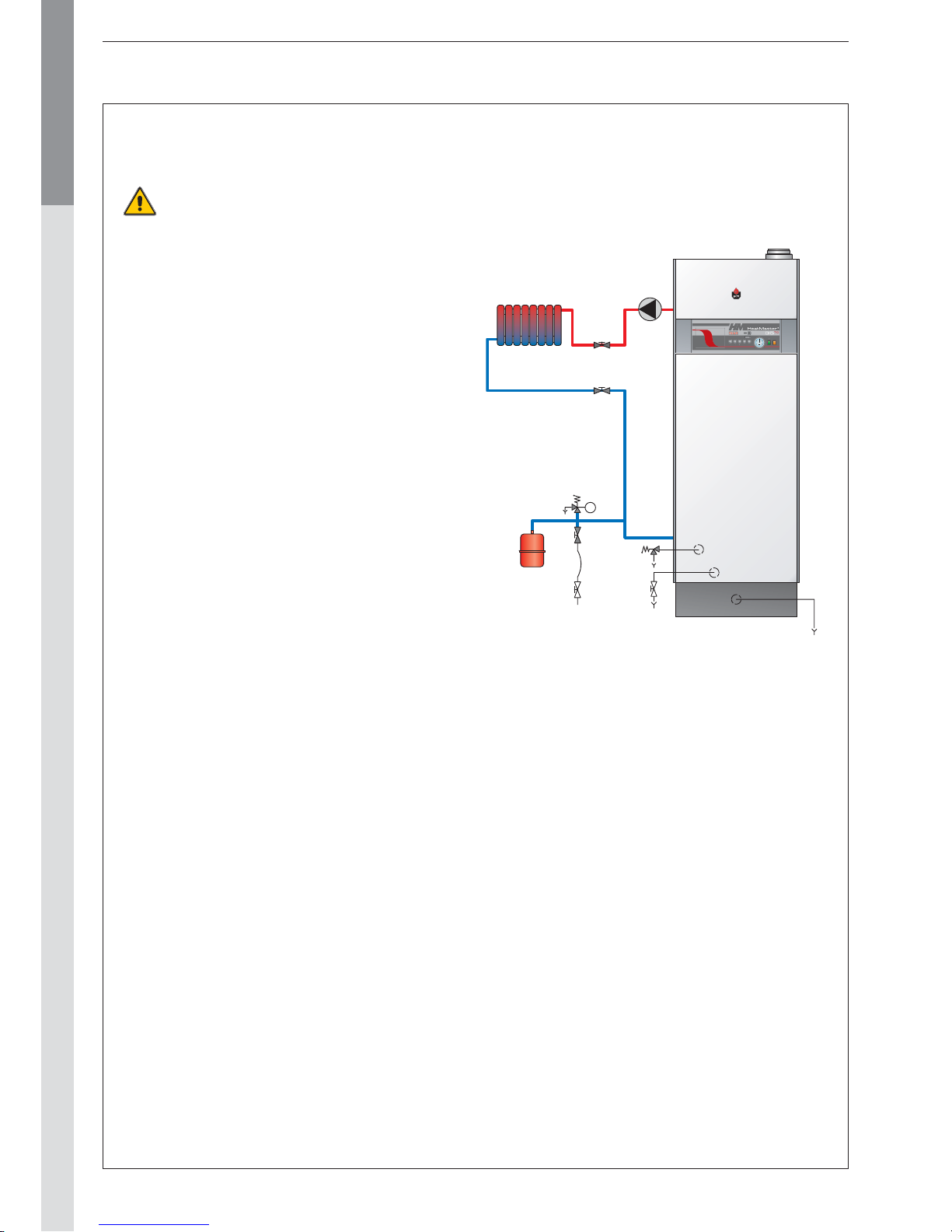
- The central heating safety valve is incorporated under the
appliance and must be routed to the drain with an open
connection (to allow inspection).
- A temperature homogeneisation pump fits the boiler.
That pump runs aswell during hot water mode aswell in
heating mode. The speed selection of the pump must be
set to 3.
- Fill the system with fresh water. Contact your ACV
representative about the use of inhibitors.
- It is possible that the pumps are locked due to the
presence of residual water from tests completed on the
appliance. Therefore, we recommend that you unblock
the pumps before filling the appliance.
- You will find the connection for the filling valve and/or
drainage valve on the bottom of the appliance. Fill the
appliance to a minimum pressure of one bar. Drain the
whole system and re-fill the appliance to a pressure of 1,5
bar.
- Fit the condenstrap, fill it with t ap wat er and connect
the hose to the drain using a connection with an
inspection section. Make sure you prevent the freezing of
the condensates.
INSTALLATION
HEATING CONNECTIONS : GENERAL
1. Isolating valve, heating system
2. Safety valve calibrated to 3 bar, with pressure gauge
3. System filling valve
4. Expansion vessel
5. Drain cock
6. Condenstrap
7. Heating pump
3
4
2
bar
2
1O3
4
1
1
5
2
6
7
Page 15
EN • 15
ENGLISHFRANCAISNEDERLANDSESPAÑOLITALIANODEUTSCH
664Y2800.B
INSTALLATION
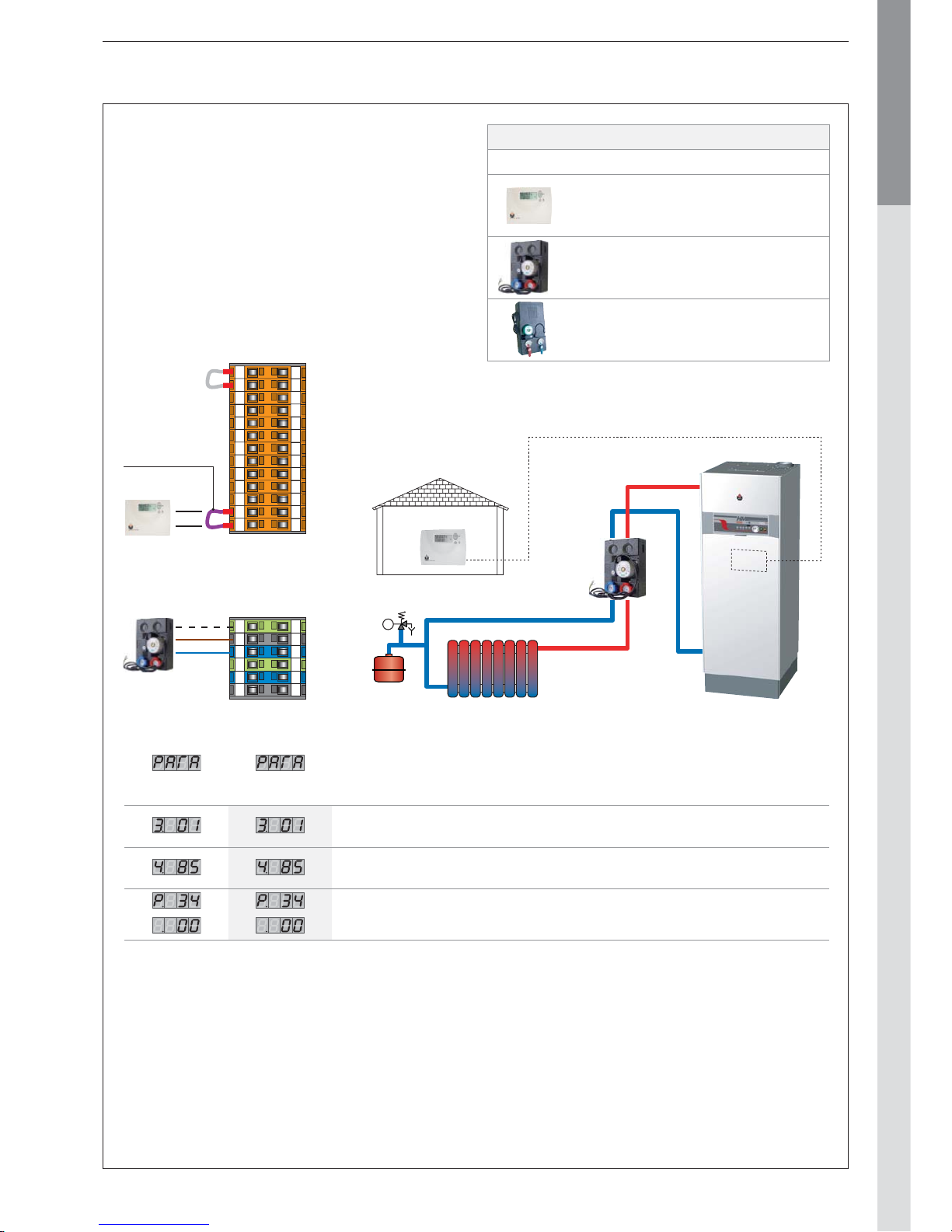
INSTALLATION OF A SINGLE HIGH
TEMPERATURE CIRCUIT WITH ROOM
THERMOSTAT ACV 15 CONTROL
General diagram
The On/Off room thermostat controls the central heating
system (radiators only).
The pump is powered as soon as the room thermost at
generates an heat demand.
Advantages for the user:
- Simplicity of the system
- Direct connecton to existing installations
ACV 15
MCBA
Factory
setting
Typical
setting Description
00 : Heating mode “OFF”
01 : Heating mode “ON”
Setting temperature for the heating water (adjustable between 30 and 85°C).
00 : Using a outside temperature sensor and a room thermostat
12345678910111213
1
2
3456789
10
11 12 13
123 546
1
2
3546
Remove this
shunt before
connectiong
a room
thermostat
Optional accessories
Code Description
10800018 Room themostat ACV 15
10800097
[HM 35 TC]
High temperature kit DN20
Including: one circulation pump,
two isolating valves, check valve,
two thermometers
10800107
[HM 85 TC]
High temperature kit DN32
Including: one circulation pump,
two isolating valves, check valve,
two thermometers
Page 16
EN • 16
ENGLISHFRANCAISNEDERLANDSESPAÑOLITALIANODEUTSCH
664Y2800.B
INSTALLATION
General diagram
This is a simple way to control two heating circuits (radiators
or floor heating) with weather depending control.
Advantages for the user:
- Comfort
- Efficiency
RAMNTC12K
MCBA
AF120
ACV 15
AM3 - 11
SQK 349
INSTALLATION OF A WEATHER DEPENDING
HEATING CIRCUIT HIGH OR LOW TEMPERATURE
Optional accessories
Code Description Code Description
10800018 Room themostat ACV 15 10510100
Outside temperature sensor
12kΩ — AF120
10800095
AM3-11 module
Controls the second heating circuit
- communicates directly with the
MCBA
10800152
[HM 35 TC]
Low temperature kit DN20
Including: one circulation pump,
two isolating valves, check valve,
two thermometers, the 3-way valve
with integrated bypass
537D3040
Contact sensor 12kΩ
To be mounted on the outlet of
controlled circuit
10800106
[HM 85 TC]
Low temperature kit DN32
Including: one circulation pump,
two isolating valves, check valve,
two thermometers, the 3-way valve
with integrated bypass
10510900
Contact thermostat RAM 5109
Required to protect all fl oor
heating circuits
10800019
Servomotor SQK 349
Electromechanical servomotor SQK
349 for the three-way valve included
in low temperature kit
(opening times :
150 seconds)
Page 17
EN • 17
ENGLISHFRANCAISNEDERLANDSESPAÑOLITALIANODEUTSCH
664Y2800.B
INSTALLATION
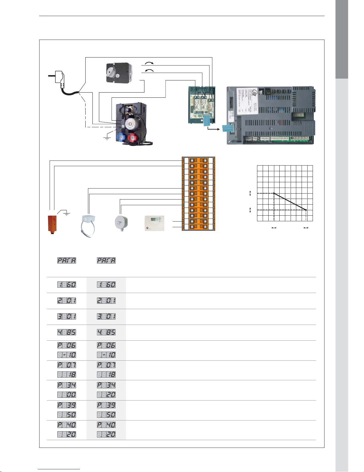
Factory
setting
Typical
setting Description
Maximum setpoint in domestic hot water mode
00 : Domestic hot water mode “OFF”
01 : Domestic hot water mode “ON”
00 : Heating mode “OFF”
01 : Heating mode “ON”
Maximum temperature of the heating circuit (must be higher than hot water setpoint)
Minimum outside temperature [T4] (adjustable between -20 and 10°C).
Maximum outside temperature [T4] (adjustable between 15 and 25°C).
10 : Heating pump controlled by room thermostat - hot water priority active
21 : Heating pump runs continuously - hot water priority active
50 : Heating pump controlled by room thermostat - hot water priority not active
61 : Heating pump runs continuously - hot water priority not active
Maximum temperature of the heating circuit
Minimum temperature of the heating circuit
N
Y2
Y1
PhPE
NN
X1
X2
X3
12345678910111213
12345678910111213
12
L
L1
To be wired in accordance with the applicable regulations.
Outside T° (°C)
90
80
70
60
50
40
30
20
10
0
-20-25 -10-15 0-5 1052015 25
P39
P40
P6 P7
T° departure boiler (°C)
Page 18
EN • 18
ENGLISHFRANCAISNEDERLANDSESPAÑOLITALIANODEUTSCH
664Y2800.B
INSTALLATION
General diagram
This configuration controls two heating circuits (radiators or floor heating). In addition, the Room unit features a remote
monit oring of the two circuits
You can adjust those t wo circuits depending on the outside temperature.
This is the ideal configuration for floor heating with additional heating provided by radiators.
You can select various heating functions, and program up to three weekly schedules, as well for the central heating as for
the hot water production.
INSTALLATION OF TWO HEATING CIRCUIT CONTROLLED
BY ROOM UNIT AND ZMC-1 MODULE
Optional accessories
Code Description Code Description
10800034
Room Unit RSC
Supplied with outside temperature
sensor
10800077
[HM 35 TC]
Collector 2 circuits DN20
With bypass, connecting tubes
and integrated wall brackets
10800119
X2
ZMC-1 module (kit)
Controls the second heating circuit
- alarm contact - operates only in
conjonction with the Room Unit
RSC.
10800152
[HM 35 TC]
X2
Low temperature kit DN20
Including: one circulation pump,
two isolating valves, check valve,
two thermometers, the 3-way valve
with integrated bypass
10800036
Clip-in interface RMCIEBV3
Enables communications between
the MCBA and the Room Unit RSC
10800104
[HM 85 TC]
Collector 2 circuits DN32
With integrated wall brackets
10800045
X2
Contact sensor 2kΩ — VF202
To be mounted on the outlet of
controlled circuit
10800142
[HM 85 TC]
Connection kit DN32 to the
manifold
Including: two fl exible 1"1/2 hoses
and 1"1/4 reduction fi ttings
10510900
Contact thermostat RAM 5109
Required to protect all fl oor heating
circuits
10800106
[HM 85 TC]
X2
Low temperature kit DN32
Including: one circulation pump,
two isolating valves, check valve,
two thermometers, the 3-way valve
with integrated bypass
10510100
Outside temperature sensor
12kΩ — AF120
10800019
X2
Servomotor SQK 349
Electromechanical servomotor SQK
349 for the three-way valve included
in low temperature kit
(opening times :
150 seconds)
RAM
MCBA
AF120
Room Unit
SQK 349
VF202
SQK 349
ZMC1
ZMC1
VF202
Page 19
EN • 19
ENGLISHFRANCAISNEDERLANDSESPAÑOLITALIANODEUTSCH
664Y2800.B
INSTALLATION
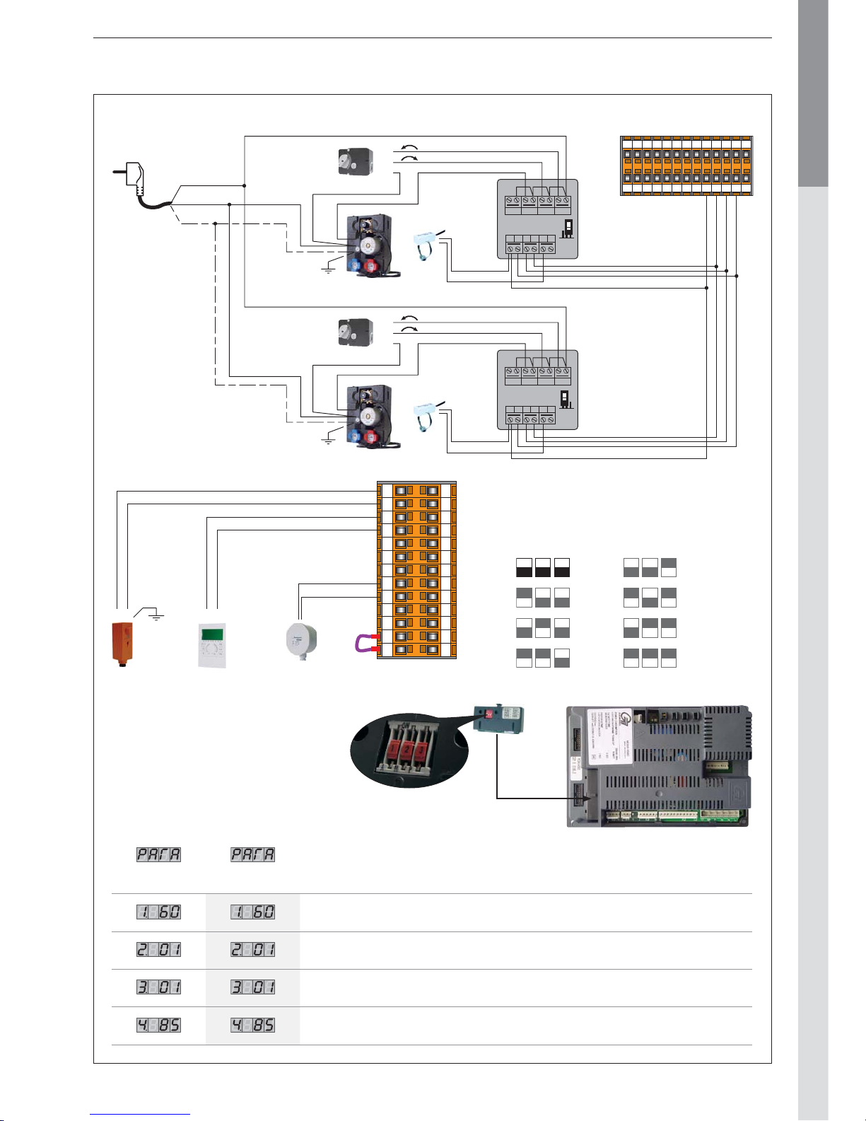
Factory
setting
Typical
setting Description
Maximum setpoint in domestic hot water mode
00 : Domestic hot water mode “OFF”
01 : Domestic hot water mode “ON”
00 : Heating mode “OFF”
01 : Heating mode “ON”
Maximum temperature of the heating circuit (must be higher than hot water setpoint)
AV MPK ZU AUF
0
24V
A B VF VE
ZMC1
N
Y1
Y2
N
B
A
AV MPK ZU AUF
0
24V
A B VF VE
ZMC1
N
Y1
Y2
N
BA
1 2 3 4 5 6 7 8 9 10111213
1 2 3 4 5 6 7 8 9 10111213
Ph
PE
N
1 2 3 4 5 6 7 8 9 10 11 12 13
1 2 3 4 5 6 7 8 9 10 11 12 13
12 AB
To be wired in accordance with the applicable regulations.
10800036: Interface address “0”
= 7
= 6
= 5
= 4
= 3
= 2
= 1
= 0
Page 20
EN • 20
ENGLISHFRANCAISNEDERLANDSESPAÑOLITALIANODEUTSCH
664Y2800.B
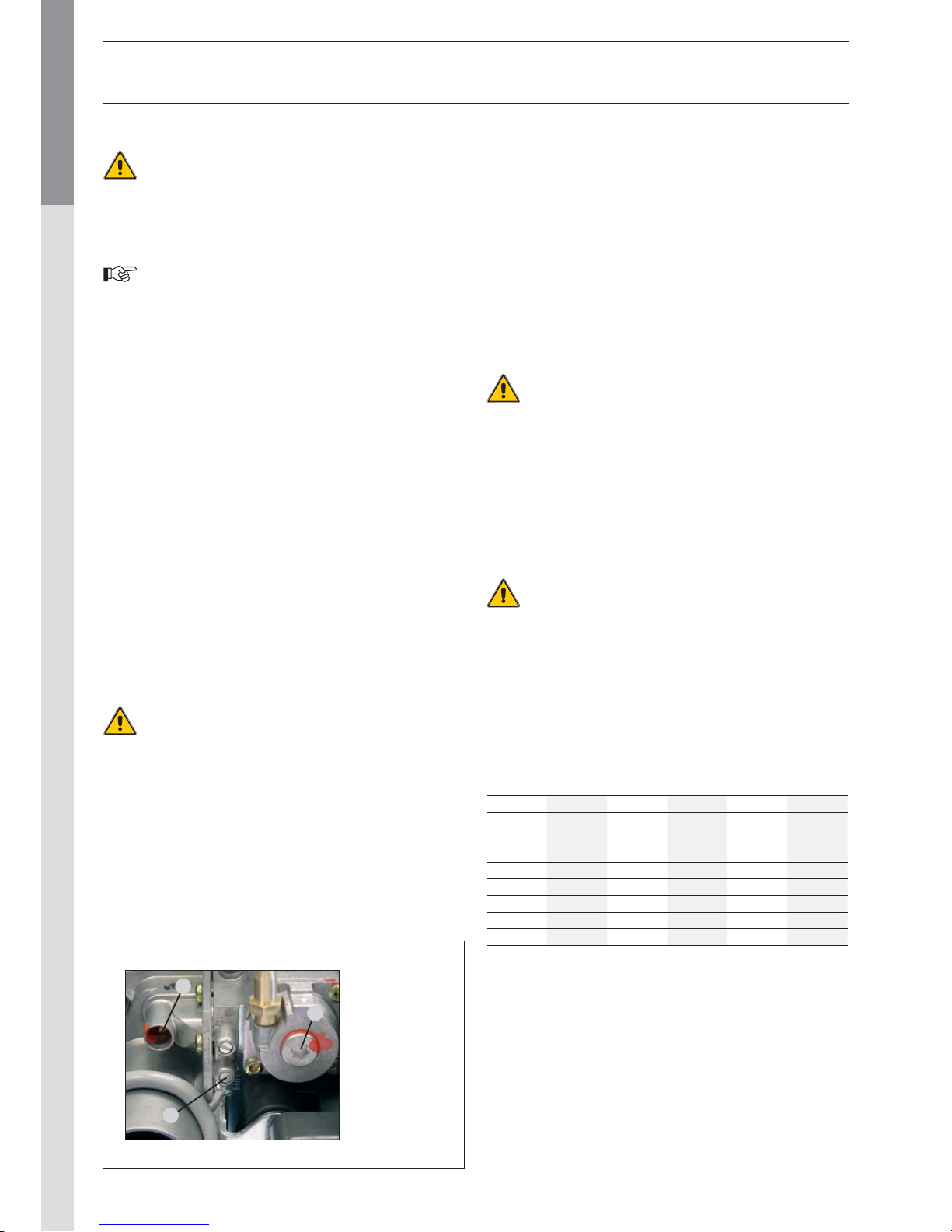
Réf. 3:
The gas valve
offset setting is
a sealed factory
setting.
In principle,
it may not be
modified.
2
1
3
COMMISSIONING THE SYSTEM
Before pressurising the central heating circuit
(primary) you should first pressurise the domestic hot
water tank (secondary).
Both the domestic hot water tank and the central
heating circuit must be filled before using the boiler.
- Slowly fill the tank and drain it by opening a hot water tap. Drain
all the taps and check that there are no leaks in the domestic
hot water system.
- Fill the whole system up to a minimum pressure of 1 bar
(preferably 1.5 bar), using the boiler’s fill valve. Fill the system
slowly. Also check that the automatic air vent on the tank is
working. Check that there are no leaks in the central heating
system.
- Vent the shunt pump and unblock it if necessary.
- Open the gas tap, drain the pipe and check that there are no
leaks in the system.
- Place the condensing trap on the bottom face of the boiler and
check it is fill with water.
- Connect the plug to the wall socket and power on the appliance. If needed, place the room thermostat to its highest
position. The boiler should start. Check the gas pressure and
allow the boiler to heat up for a few minutes. Set the boiler
to High Power mode and check the CO2 level (see the table
of Technical Characteristics)
. Then, set the boiler to Low Power
mode and check the CO2 level again (see the table of Technical
Characteristics)
.
- Set the central heating and hot water temperatures following
the values given in the Directions for Use.
- Drain the central heating system again and, if necessary, re-fill it.
- Make sure the central heating system is correctly balanced
and, if necessary, adjust the valves to prevent a greater or
lesser flow than planned to some circuits or radiators.
The condensate flow pipe diameter can not be decreased.
Moreover this pipe can never be blocked.
CHECKING THE SETTINGS
- Check that the parameters are set in accordance with the
user’s needs: see page 3, Directions for Use.
- Check the boiler settings: this task can only be carried out by an
ACV-trained installer or by the ACV maintenance department.
- Set the appliance to High Power mode by simultaneously pressing
the mode and Plus keys.
COMMISSIONING AND MAINTENANCE
- Check the dynamic gas pressure at the gas valve (see diagram
below, ref. 1)
. This must be at least 18 mbars. Wait a few minutes for the appliance to heat up to a minimum temperature of
60°C. Check the CO2 setting using a measurement instrument.
Please see in the Technical Characteristics for optimum value.
To increase the CO2 value, turn the venturi screw counterclockwise;
turn it clockwise to reduce the value (see diagram below ref. 2).
Then put the appliance to High Power mode by simultaneously
pressing the mode and Plus keys. Wait a few minutes to stabilise.
Check the CO2 value. It should be either equal to the full power
value or a maximum of 0.5% less than this value. If you record
a significant deviation,please contact the ACV maintenance
department.
INSPECTION AND MAINTENANCE
ACV recommends that you have your boilers inspected
and cleaned if need be at least once a year.
Plug out the appliance before undertaking any work, even if only
recording measurements and adjusting the settings.
- Check that the condenstrap is not fouled, fill it, if need be, and
check that there are no leaks.
- Check that the safety valves are operating correctly.
- Drain the whole system and if necessary re-fill the appliance to
pressure of 1.5 bar.
If you have to refill your circuit more than twice a year,
please contact your installer.
- Check the boiler charge in High Power mode. If there is a
big difference between this value and the original setting, the
deviation could mean a blockage in the air intake pipes or flue
gas extraction pipes, or that the exchanger has become fouled
with an accumulation of dirt.
TEMPERATURE SENSOR RESISTANCE TABLES
T° [°C] R Ω T° [°C] R Ω T° [°C] R Ω
- 20 98200 25 12000 70 2340
- 15 75900 30 9800 75 1940
- 10 58800 35 8050 80 1710
- 5 45900 40 6650 85 1470
0 36100 45 5520 90 1260
5 28600 50 4610 95 1100
10 22800 55 3860 100 950
15 18300 60 3250
20 14700 65 2750
Page 21
EN • 21
ENGLISHFRANCAISNEDERLANDSESPAÑOLITALIANODEUTSCH
664Y2800.B
COMMISSIONING AND MAINTENANCE
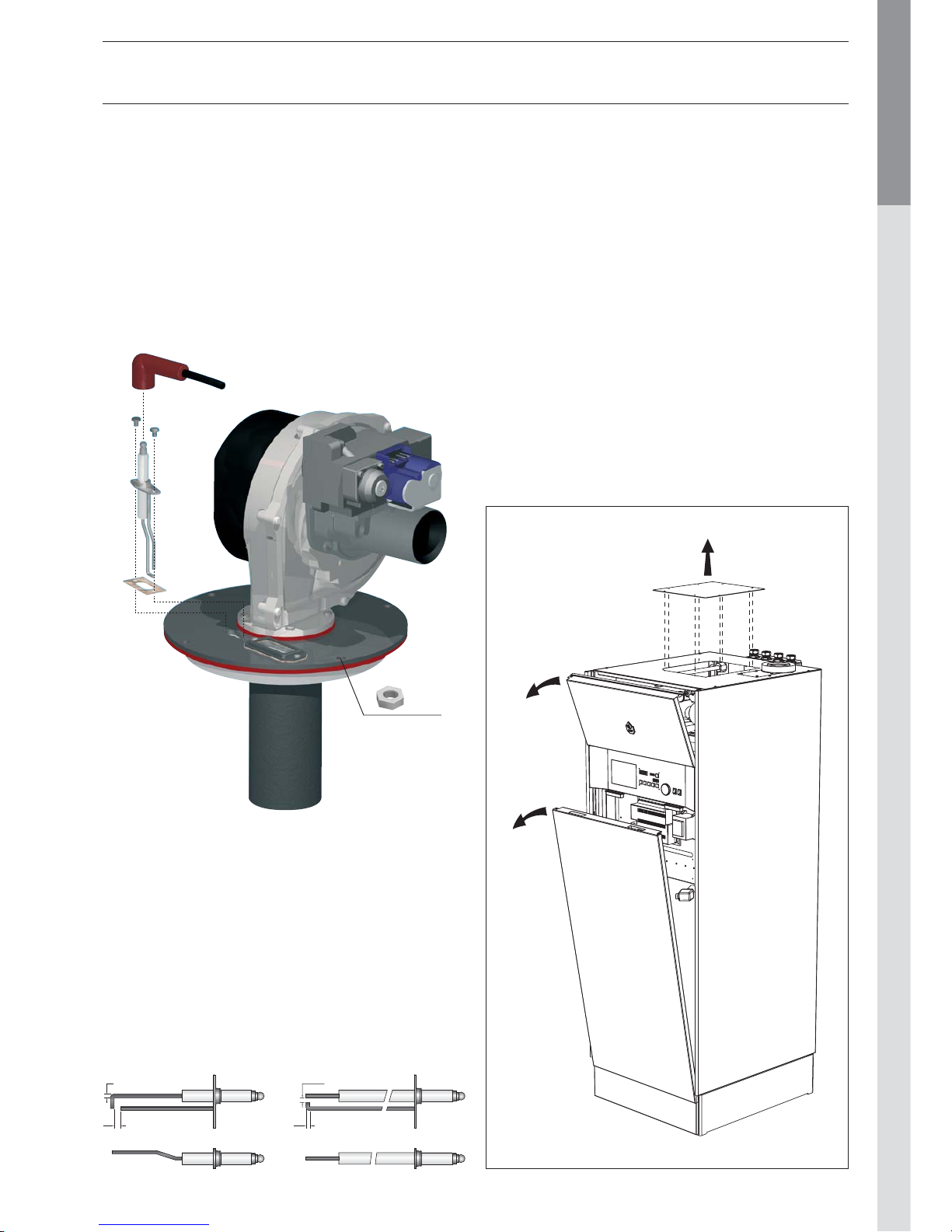
DISASSEMBLING THE BURNER
- Close the inlet gas valve.
- Remove the top front panel of the boiler.
- Unplug the fan plug(s), the ignition cable, the gas valve control
and the ignition electrode earth.
- Loosen the 4 burner nuts using a ratchet wrench.
- Unscrew the three-way coupling on the gas pipe.
- In one unit, lift up the burner with the fan and the gas valve to
remove them from the exchanger. Be careful not to damage
the burner insulation in the exchanger.
- Check the condition of the insulation and the seals and replace
them if necessary before re-assembling the burner following
the same procedure but in the reverse order.
CLEANING THE HEAT EXCHANGER
- Remove the burner assembly as described above.
- Remove the burner gasket.
- Clean the combustion chamber using a vacuum cleaner.
- It could be necessary to clean the flue tubes by putting water
in the combustion room. After that operation, it is necessary
to clean the condensing trap.
- Check the burner insulation and the burner gasket; replace
the parts if necessary.
- Check the igniter, replace if necessar y
- Reassemble the burner and check for leakages.
- Power up the appliance, set the boiler in full power mode and
recheck for leaks.
- Check the gas pressure and the CO2 level as explained in
previous paragraf.
DISASSEMBLING AND CHECKING THE ELECTRODE
- Remove the ignition cable.
- Remove the two fixing screws.
- Remove the electrode earth but make sure the serrated
washer is fixed between the earth cable and the electrode
when re-assembling.
- Check the condition of the seals and replace them if necessary
before re-assembling the electrode following the same procedure
but in the reverse order.
X 4
3
5
3 - 4
3
HeatMaster® 35 TC HeatMaster® 85 TC
Page 22
EN • 22
ENGLISHFRANCAISNEDERLANDSESPAÑOLITALIANODEUTSCH
664Y2800.B
MCBA PARAMETERS FOR THE SPECIALIST
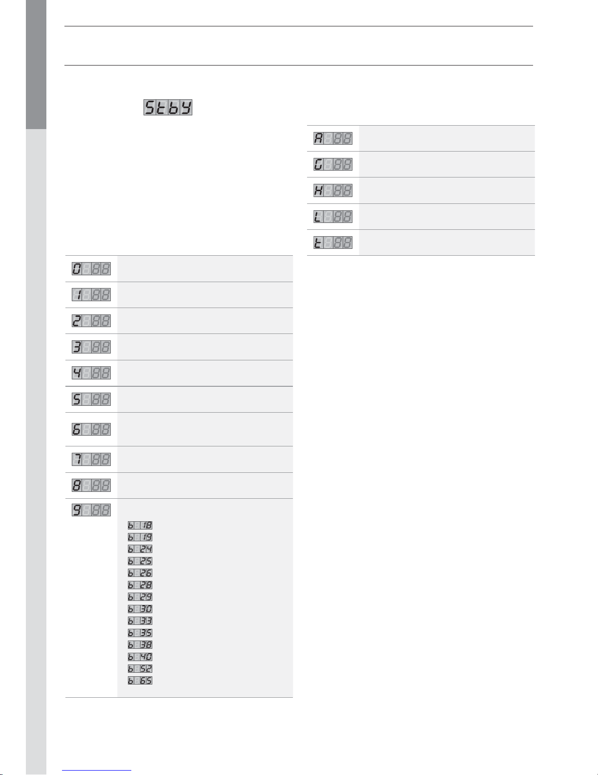
STANDBY MODE
Standby Mode
After you power down the appliance the screen displays Pilot
mode, as shown in the figure above.
This is the standard MCBA mode. The MCBA automatically
returns to this mode after 20 minutes if no keys have been
pressed on the screen. Any parameters that were modified are
then enabled.
The first character shows the current status of the boiler
depending on the condition of both the boiler and the burner. The
last 2 characters indicate the start temperature.
Once the cause of the blockage has been resolved, the burner
starts automatically within 150 seconds at most.
If the burner is blocked for one of the reasons mentioned above,
the screen display alternates between a 9 followed by the
temperature (two last digits) and b with the error code.
Status Boiler function
Standby, no demand for heat
Fan first, fan after
Ignition
Operation of the boiler burner for the heating
Operation of the boiler burner for the
domestic hot water
Air pressure limit or obtaining
the number of start revolutions
The burner goes out when the specified value
is reached.
A demand for heat is present nonetheless.
Pump over-run time after the demand for
central heating
Pump over-run time after the demand for
domestic hot water
Burner blocked:
• : T1 > 95°C
•
: T2 > 95°C
•
: T2 - T1 > 10°C after 90 seconds
•
: dT1/dt > maximum gradient T1
•
: water pressure switch not off
•
: no fan signal
•
: erroneous fan signal
•
: T1 - T2 > Δ max.
•
: NTC3 short-circuit
•
: NTC5 short-circuit
•
: NTC3 interrupt
•
: NTC5 interrupt
•
: T5 > T5 max
•
: wait for the fan to start
Status Boiler function
Internal check — three-way valve
Boiler burner in hot water ready function
Test function: Central heating high power
Test function: Central heating low power
Test function: Boiler with fixed number of
revolutions
Page 23
EN • 23
ENGLISHFRANCAISNEDERLANDSESPAÑOLITALIANODEUTSCH
664Y2800.B
MCBA PARAMETERS FOR THE SPECIALIST
SETTING THE MCBA PARAMETERS
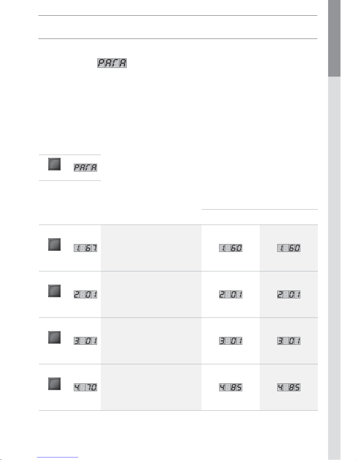
Parameter Mode
To access Parameter mode when the system is in Pilot mode, press MODE once.
To scroll through the list of parameters, simply press “step”. To modify a parameter value, use the + or - keys.
Then press “Store” to save the value you just changed. The screen flashes once to confirm the data has been saved.
To activate the parameters you changed, press MODE once more (which brings you into Info mode). However, if you do not press a
key, the system returns to Pilot mode after 20 minutes and automatically enables the changes.
Factory setting
Key Screen Description of parameters
HeatMaster
®
35 TC
HeatMaster
®
85 TC
STEP
Adjusting the hot water temperature
STEP
Production
of hot water
00 = Stop
01 = Start
STEP
Turn On/
Turn Off
the heating
00 = Stop
01 = Start
STEP
Maximum temperature in
Central Heating mode
Key Screen
MODE
Page 24
EN • 24
ENGLISHFRANCAISNEDERLANDSESPAÑOLITALIANODEUTSCH
664Y2800.B
MCBA PARAMETERS FOR THE SPECIALIST
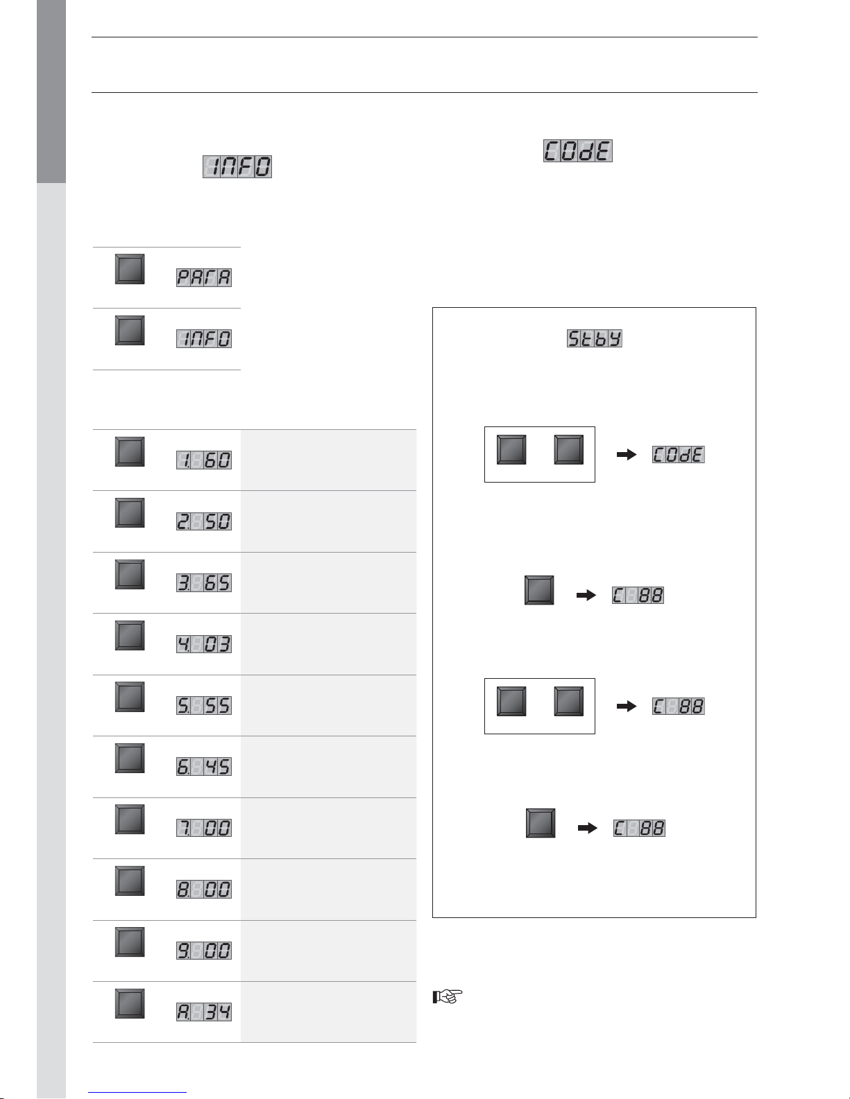
ENTERING THE CODE
Code Mode
You can access the following parameters by entering the service
code:
• Parameters 5 - 42
• Communication mode
• Fan Speed mode
• ERROR mode
Only ACV authorised installers know the access code.
For further information, please contact our after-sales
department.
To access Code mode, press
MODE and STEP simultaneously
[only from Standby mode!].
MODE STEP
Press STEP once and the system displays C
in position 1, followed by arbitrary
characters in positions 3 and 4.
STEP
Press + or - to change the code.
+ -
Press STORE, the screen flashes briefly
to indicate that the code has been accepted.
STORE
Press MODE until the system
displays the correct mode.
REQUEST FOR INFORMATION
ON THE INSTALLATION
Info Mode
To switch from Standby to Info mode, press Mode twice.
Key Screen
Description of
parameters
STEP
Boiler temperature T1
[Top of the primary]
STEP
Boiler temperature T2
[Top of the primary]
STEP
Hot water temperature T3 in °C
[Bottom of the hot water tank]
STEP
Outdoor temperature T4 in °C
STEP
Flue gas temperature
STEP
Calculated boiler
temperature in °C
STEP
Rate of increase of T1
temperature in °C/s
STEP
Rate of increase of T2
temperature in °C/s
STEP
Rate of increase in the hot water
temperature in °C/s
STEP
Flow temparature of the heating
circuit (with module AM3-11 only)
Key Screen
MODE
MODE
Press STEP until the system
displays the information you
need. The point located behind
the first position flashes to
indicate that the boiler is in
INFO mode.
or
Page 25
EN • 25
ENGLISHFRANCAISNEDERLANDSESPAÑOLITALIANODEUTSCH
664Y2800.B
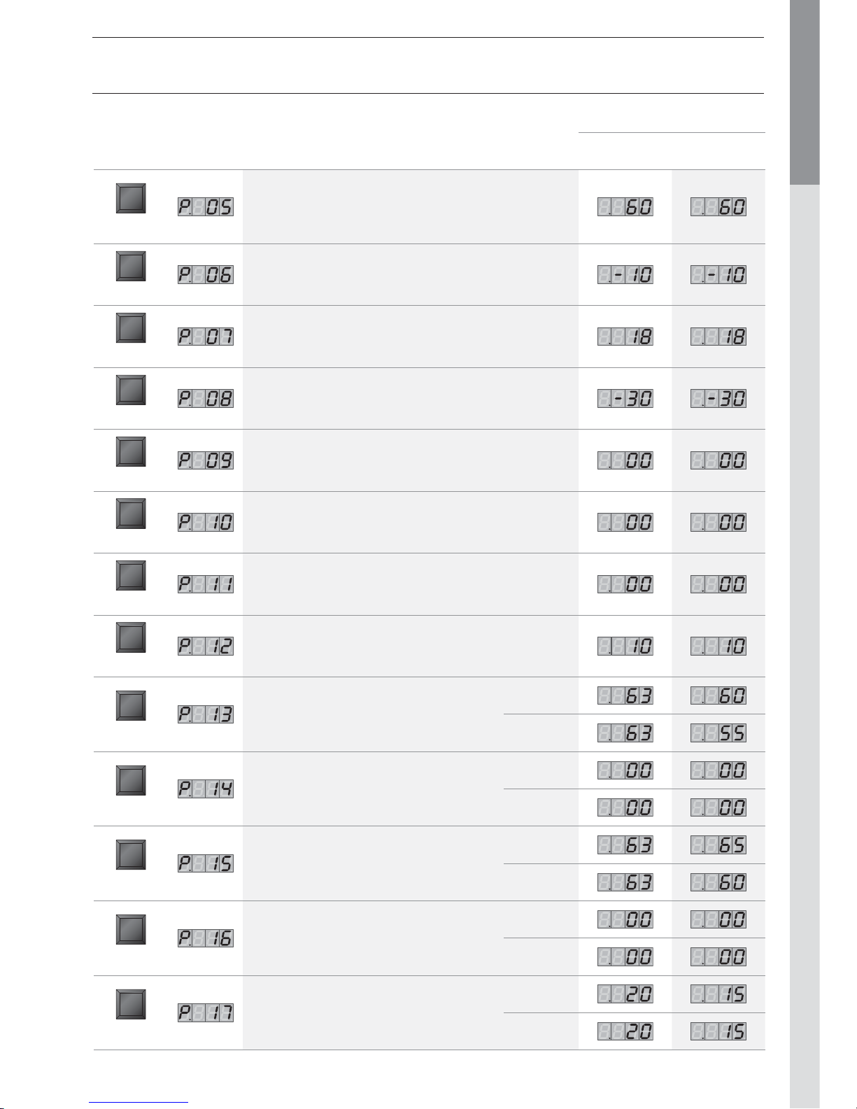
MCBA PARAMETERS FOR THE SPECIALIST
Factory setting
Key Screen Description of parameters HM 35 TC HM 85 TC
STEP
Minimum temperature of the top part of the boiler in heating mode
when using an outdoor sensor
In order to avoid cycling between heating and hot water mode, it is
preferable to set that parameter higher than DHW set point [Para 1]
STEP
Minimum outdoor temperature [adjust the heating curve]
STEP
Maximum outdoor temperature [adjust the heating curve]
STEP
Frost protection temperature
STEP
Correction of outdoor temperature
STEP
Blockage T
0 = Disabled
STEP
Acceleration time lag
00 = Stop [minute]
STEP
Night reduction heating (°C)
STEP
Maximum number of fan revolutions in CH mode
[rpm x 100]
Natural gas
Propane
STEP
Maximum number of fan revolutions in CH mode
[rpm /min.]
Natural gas
Propane
STEP
Max. number of revs in domestic hot water mode
[rpm x 100]
Natural gas
Propane
STEP
Maximum number of fan revolutions in domestic
hot water mode [rpm]
Natural gas
Propane
STEP
Minimum number of fan revolutions [rpm x 100]
Natural gas
Propane
MCBA PARAMETERS WITH CODE RESTRICTED ACCESS
Page 26
EN • 26
ENGLISHFRANCAISNEDERLANDSESPAÑOLITALIANODEUTSCH
664Y2800.B
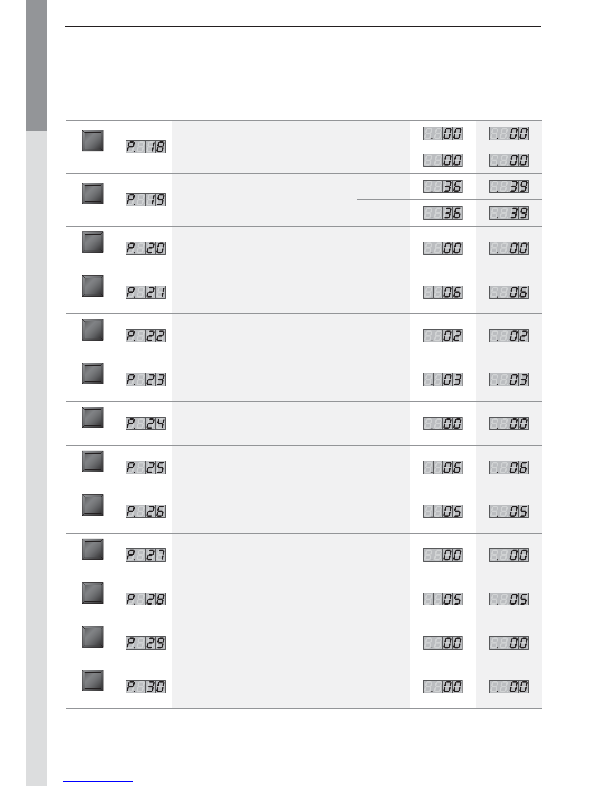
MCBA PARAMETERS FOR THE SPECIALIST
Factory setting
Key Screen Description of parameters HM 35 TC HM 85 TC
STEP
Minimum number of fan revolutions [rpm]
Natural gas
Propane
STEP
Number of fan revolutions at ignition [rpm x 100]
Natural gas
Propane
STEP
CH pump over-run
0 = 10 sec. [step = 1 minute]
STEP
Domestic hot water pump over-run time
[step = 10.2 sec]
STEP
Central Heating modulation hysteresis enabled
STEP
Central Heating modulation hysteresis disabled
STEP
Domestic hot water modulation hysteresis enabled
STEP
Domestic hot water modulation hysteresis disabled
STEP
Detection of domestic hot water hysteresis enabled
STEP
Detection of domestic hot water hysteresis disabled
STEP
Central Heating blockage time
[sec. x 10,2]
STEP
Domestic hot water blockage time
[sec. x 10,2]
STEP
Domestic hot water Central Heating
blockage time [sec. x 10,2]
Page 27
EN • 27
ENGLISHFRANCAISNEDERLANDSESPAÑOLITALIANODEUTSCH
664Y2800.B
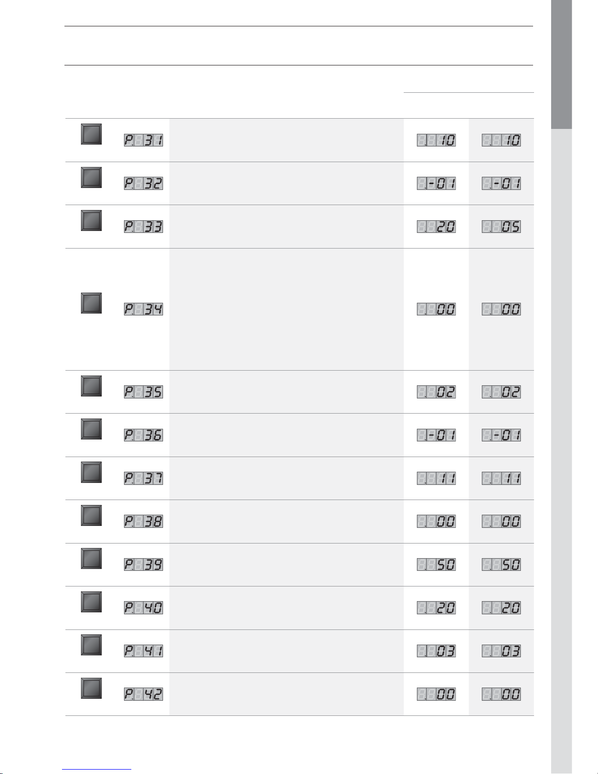
MCBA PARAMETERS FOR THE SPECIALIST
Factory setting
Key Screen Description of parameters HM 35 TC HM 85 TC
STEP
Re-modulate the difference T1 - T2
STEP
Bus address
[-1 = disabled]
STEP
Temperature increase set point
for the production of hot water
STEP
00 : High temperature circuit - heating pump controlled by room
thermostat - hot water priority active
10 : Controlled circuit (outside sensor + AM3-11 module) - heating
pump controlled by room thermostat - hot water priority active
21 : Controlled circuit (outside sensor + AM3-11 module) - heating
pump runs continuously - night reduction possible - hot water
priority active
50 : Controlled circuit (outside sensor + AM3-11 module) - heating
pump controlled by room thermostat - hot water priority not
active
61 : Controlled circuit (outside sensor + AM3-11 module) - heating
pump runs continuously - night reduction possible - hot water
priority not active
STEP
Selection of the type of hot water production - That parameter is
fixed in a HeatMaster® TC and must not be changed
STEP
Manual fan speed
STEP
First position: PWM pump level during burning in, not used
Second position: PWM pump level during over-run time, not used
STEP
T set hold boiler warm
STEP
Maximum temperature for the 2nd heating circuit
STEP
Minimum temperature for the 2nd heating circuit
STEP
2nd circuit temperature hysteresis
STEP
First position: Special pump [0 = disabled]
Second position: Minimum disable cycle [0 = disabled]
Page 28
EN • 28
ENGLISHFRANCAISNEDERLANDSESPAÑOLITALIANODEUTSCH
664Y2800.B
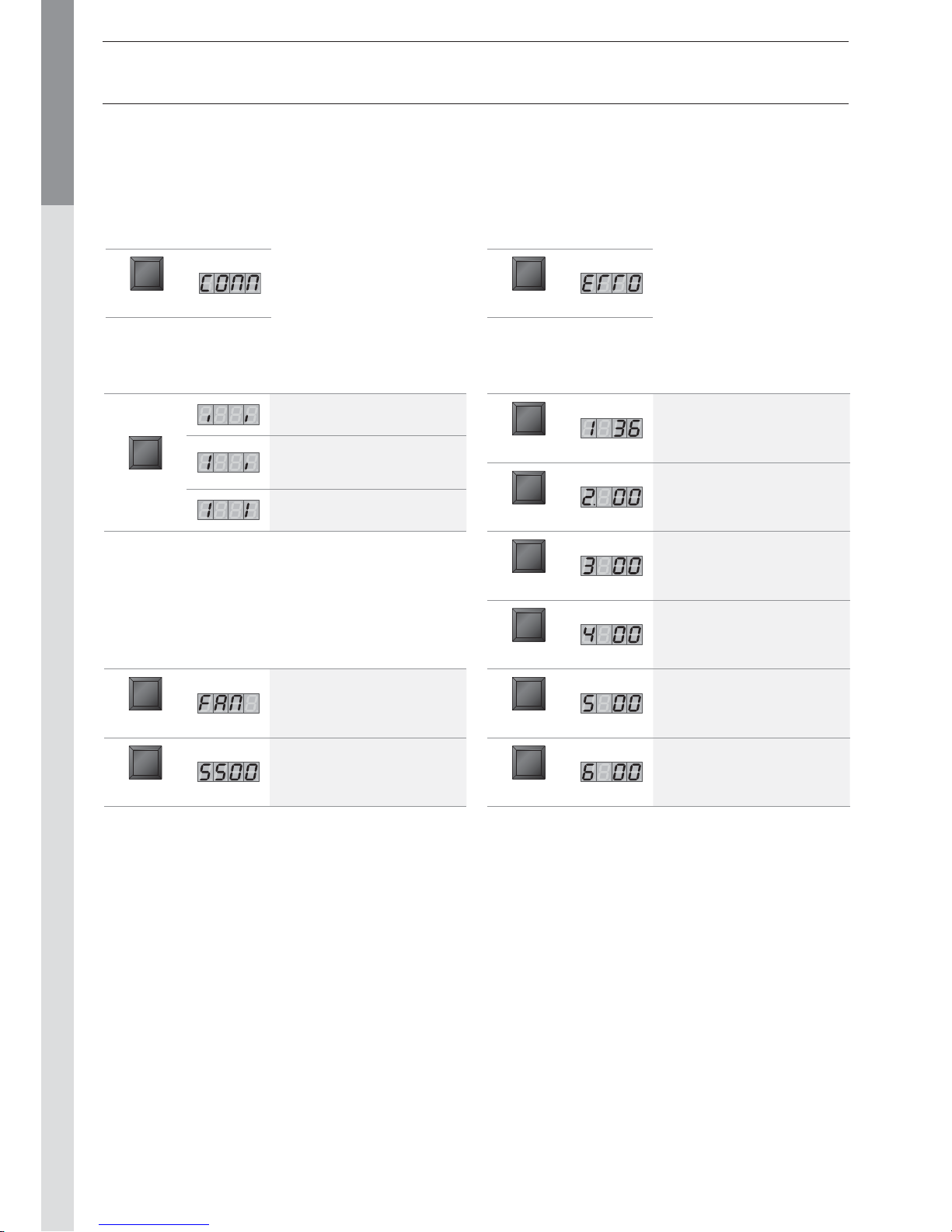
ERROR MODE [with code]
ERROR mode indicates the most recent error, as well as the status
of the boiler and its readings at the time this error occurred.
Key Screen
MODE
COMMUNICATION MODE [with code]
When in this mode, the system displays the communication
between the boiler and the control module, the optional interface
kit or the optional programmable room thermostat.
Key Screen
MODE
Key Screen
Description of
parameters
STEP
Code error of the last lock-out
STEP
Status of the boiler at the time
of the error
STEP
Temperature T1 at the time
of the error
STEP
Temperature T2 at the time
of the error
STEP
Hot water temperature T3 at
the time of the error
STEP
Outdoor temperature T4 at the
time of the error
Key Screen
Description of
parameters
STEP
No communication
Communication between the
boiler module and the optional
control modules only
Communication between all the
devices connected
Key Screen
Description of
parameters
MODE
Fan speed
STEP
The current fan speed is
5.500 rpm.
FAN MODE [with code]
MCBA PARAMETERS FOR THE SPECIALIST
Page 29
EN • 29
ENGLISHFRANCAISNEDERLANDSESPAÑOLITALIANODEUTSCH
664Y2800.B
MCBA PARAMETERS FOR THE SPECIALIST
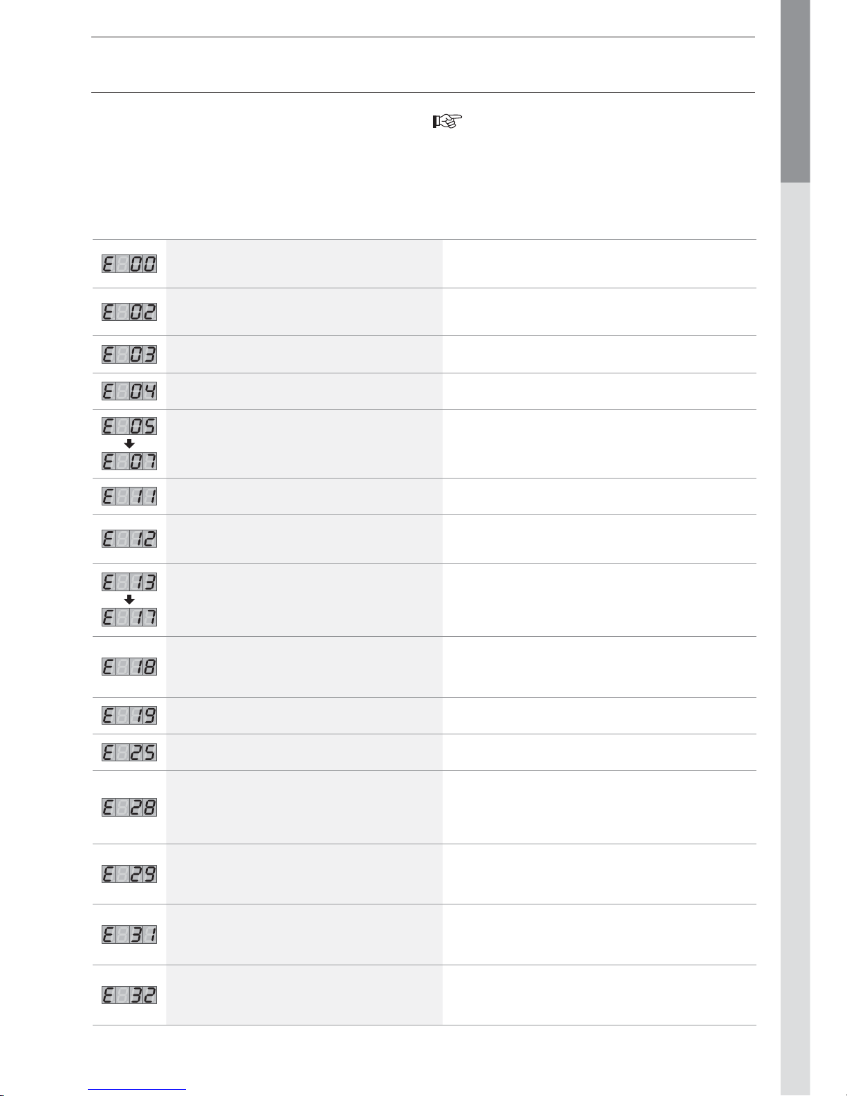
Codes Description of the fault Resolution of the fault
Abnormal flame signal
- Check the wiring (short-circuit in the 24V wiring)
- Check the electrode
- Replace the MCBA (water damage)
No flame signal after five attempts at firing the boiler
- Check the ignition cable
- Check the electrode and the position of the electrode
- Check that there is gas at the burner.
Rectifier or gas valve error Replace the rectifier or the gas valve
Persistent lock Press “RESET”
Internal error
If the problem persists after two RESET attempts,
replace the MCBA.
EPROM error
If the problem persists after two RESET attempts,
replace the MCBA.
Max input, thermostat open or 24V fuse gone.
- Check the wiring
- Check the 24V fuse on the MCBA.
- Shunt12-13 missing
Internal error
If the problem persists after two RESET attempts,
replace the MCBA.
T1 > 110°C
- Check the NTC wiring and replace if necessary.
If NTC1 is OK, please verify that the water flows trough the
boiler.
T2 > 110°C - Check the NTC wiring and replace if necessary.
T1 gradient too high
- Check that the pump is turning.
- If there is no problem with the pump, drain the system.
No fan signal present
- Check the fan control connection
- Check the fan wiring
If the problem persists after two RESET attempts,
replace the MCBA.
The tacho signal of the blower does’nt go to zero.
- Check that the convection flow through the chimney is not
high enough to rotate the blower.
If not, exchange the blower.
NTC1 short-circuit
- Check the connection of the NTC1 sensor
- Check the wiring of the NTC1 sensor
If the problem persists, replace the NTC1 sensor
NTC2 short-circuit
- Check the connection of the NTC2 sensor
- Check the wiring of the NTC2 sensor
If the problem persists, replace the NTC2 sensor
To unlock the system:
• Press RESET on the screen.
• Contact your installer if the fault happens again.
SAFETY STOP [ERROR mode]
If a fault occurs while the appliance is running, the system locks
and the screen starts to flash. The first character is an E and
the next two characters give the code for this fault, as illustrated
in the table below.
Page 30
EN • 30
ENGLISHFRANCAISNEDERLANDSESPAÑOLITALIANODEUTSCH
664Y2800.B
MCBA PARAMETERS FOR THE SPECIALIST
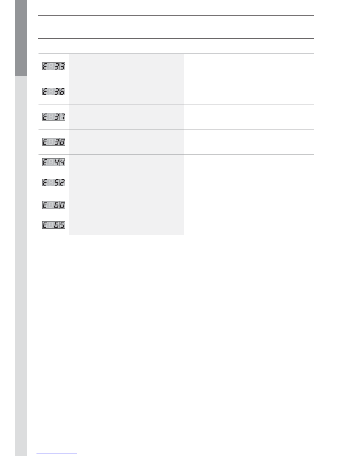
Codes Description of the fault Resolution of the fault
NTC3 short-circuit
- Check the connection of the NTC3 sensor
- Check the wiring of the NTC3 sensor
If the problem persists, replace the NTC3 sensor
NTC1 connection open
- Check the connection of the NTC1 sensor
- Check the wiring of the NTC1 sensor
If the problem persists, replace the NTC1 sensor
NTC2 connection open
- Check the connection of the NTC2 sensor
- Check the wiring of the NTC2 sensor
If the problem persists, replace the NTC2 sensor
NTC3 connection open
- Check the connection of the NTC3 sensor
- Check the wiring of the NTC3 sensor
If the problem persists, replace the NTC3 sensor
Internal error
If the problem persists after two RESET attempts,
replace the MCBA.
Flue gas temperature too high (NTC5)
- Check the connection of the NTC5 sensor
- Check the wiring of the NTC5 sensor
If the problem persists, replace the NTC5 sensor
Error while reading the parameters
Press RESET
If the error persists, replace the MCBA.
Problem with the power supply to the fan
- Check the MCBA power supply voltage.
If it is OK, replace the fan.
 Loading...