

Heatmaster 25 Tc, 85 TC, 35 TC, 120 TC, 45 TC Installation, Operation And Maintenance Instructions
...Page 1

664Y6800 • A
INSTALLATION, OPERATION AND
MAINTENANCE INSTRUCTIONS
25 - 35 - 45 - 70 - 85 - 120 TC
HeatMaster
®
EN
FR
NL
ES
IT
DE
PL
RU
INSTALLATION, OPERATION AND
MAINTENANCE INSTRUCTIONS
Page 2

en
2
Heat Master TC : 6 64Y6800 • A
EN
FR
NL
ES
IT
DE
PL
RU
TABLE OF CONTENTS
GENERAL RECOMMENDATIONS ...................................................................4
USER'S GUIDE ...............................................................................................5
Instructions for the end user ............................................................................................................................................. 5
Periodic checks ....................................................................................................................................................................5
Control panel ....................................................................................................................................................................... 6
Parameter setting ...............................................................................................................................................................7
APPLIANCE DESCRIPTION ..........................................................................10
Burner description ............................................................................................................................................................12
TECHNICAL CHARACTERISTICS .................................................................13
Burner characteristics .......................................................................................................................................................13
Single gas categories (All models)..................................................................................................................................14
Double gas categories (HM 70 / 85 / 120 TC only)........................................................................................................16
Combustion characteristics.............................................................................................................................................18
Electrical characteristics (HM TC equipped with a standard charging pump)........................................................20
Electrical characteristics (HM TC < 70 kw equipped with a high eciency pump) ...............................................22
Electrical characteristics (HM TC ≥ 70 kw equipped with a high eciency pump)................................................24
Dimensions ........................................................................................................................................................................26
Chimney connection characteristics .............................................................................................................................28
Calculation of the ue pressure drop, or of the corresponding length in meters of straight pipes ...................30
Hydraulic characteristics ..................................................................................................................................................32
DHW performance ............................................................................................................................................................34
Maximum operating conditions .....................................................................................................................................34
INSTALLATION ........................................................................................... 35
Package contents .............................................................................................................................................................. 35
How to move the boiler ...................................................................................................................................................36
Safety instructions for the installation .......................................................................................................................... 37
Recommendations for the prevention of corrosion and scaling ..............................................................................39
Tools required for the installation ..................................................................................................................................41
Boiler preparation ............................................................................................................................................................. 41
DHW connection ...............................................................................................................................................................43
Heating connection ..........................................................................................................................................................44
Gas connection ..................................................................................................................................................................46
Conversion to propane (HM 85 / 120 TC).......................................................................................................................47
Gas circuit connection......................................................................................................................................................48
Page 3

en
3
Heat Master TC : 6 64Y6800 • A
EN
FR
NL
ES
IT
DE
PL
RU
TABLE OF CONTENTS
STARTING UP .............................................................................................49
Safety instructions for starting up .................................................................................................................................49
Tools required for starting up .........................................................................................................................................49
Checks before starting up ...............................................................................................................................................49
Filling the system .............................................................................................................................................................. 50
Starting up the boiler ....................................................................................................................................................... 51
Checking and adjusting the burner ............................................................................................................................... 52
MAINTENANCE ..........................................................................................53
Safety instructions for the boiler maintenance ...........................................................................................................53
Tools required for maintenance .....................................................................................................................................54
Boiler shut down for maintenance .................................................................................................................................54
Periodic boiler maintenance tasks ................................................................................................................................. 55
Removal, check and reinstallation of the burner electrode.......................................................................................56
Removal and reinstallation of the burner .....................................................................................................................57
Cleaning the exchanger ...................................................................................................................................................58
Removing and cleaning the condensate recovery dish .............................................................................................59
Draining the boiler ............................................................................................................................................................60
Restarting after maintenance .........................................................................................................................................61
In case of problem... ..........................................................................................................................................................62
DECLARATION OF CONFORMITY EC ........................................................63
For specific connection diagrams and the list of associated accessories, the MCBA
parameters and the error codes, refer to the System Control manual provided with
this product.
Page 4

NOTE
This manual contains important information with respect to the installation, the starting up and the
maintenance of the boiler.
This manual must be provided to the user, who will read it carefully and keep it in a safe place.
We accept no liability should any damage result from the failure to comply with theinstructions
contained in this technical manual.
Essential recommendations for safety
• It is prohibited to carry out any modifications to the appliance without the
manufacturer’s prior and written agreement.
• The product must be installed by a qualified engineer, in accordance with
applicable local standards and regulations.
• The installation must comply with the instructions contained in this manual and
with the standards and regulations applicable to installations.
• Failure to comply with the instructions in this manual could result in personal
injury or a risk of environmental pollution.
• The manufacturer declines all liability for any damage caused as a result of
incorrect installation or in the event of the use of appliances or accessories that are
not specified by the manufacturer.
Essential recommendations for the correct operation of the appliance
• In order to ensure that the appliance operates correctly, it is essential to have it
serviced by a certified installer or maintenance contractor every year.
• In case of anomaly, please call your service engineer.
• Faulty parts may only be replaced by genuine factory parts.
en
4
Heat Master TC : 6 64Y6800 • A
EN
FR
NL
ES
IT
DE
PL
RU
GENERAL RECOMMENDATIONS
Page 5

If you smell gas:
- Immediately isolate the gas supply.
- Open windows and doors to ventilate the area.
- Do not use any electrical appliances and do not operate any switches.
- Immediately notify your gas supplier and/or your installer.
en
5
Heat Master TC : 6 64Y6800 • A
EN
FR
NL
ES
IT
DE
PL
RU
USER'S GUIDE
INSTRUCTIONS FOR THE END USER
Essential recommendations for safety
• Do not store any flammable or corrosive products, paint, solvents, salts, chloride
products and other detergent products near the appliance.
• This appliance is not intended for use by persons (including children) with reduced
physical, sensory or mental capabilities, or lack of experience and knowledge,
unless supervised or unless they have been given instruction concerning the use
of the appliance by a person responsible for their safety.
PERIODIC CHECKS
Essential recommendations for the correct operation of the appliance
• Make sure that the system water pressure is at least 1 bar when cold.
• If it is required to top up the system to maintain the minimum recommended water
pressure, only add small amounts of water at a time. If a large amount of cold water
is added in a hot boiler, the boiler can be damaged definitively.
• If the system needs to be refilled repeatedly with water, please contact your
installer.
• Regularly check that there is no water on the floor in front of the boiler. If there is,
please call your service engineer.
General remark
• Checking the boiler settings can only be carried out by an ACV-trained installer or
by ACV's maintenance department.
Page 6

bar
2
1O3
4
2
5
4
1
3
en
6
Heat Master TC : 6 64Y6800 • A
EN
FR
NL
ES
IT
DE
PL
RU
USER'S GUIDE
CONTROL PANEL
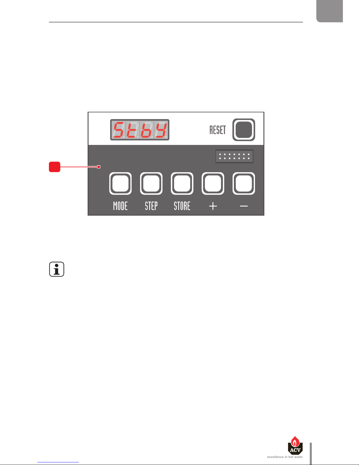
When the boiler is powered on, it starts in Stand-by mode and displays for 2
seconds before displaying the boiler status.
Description
1. ON/OFF master switch of the boiler - The built-in indicator lights when the appliance is turned on.
2. Summer-winter switch - To activate or deactivate the heating pump. The built-in indicator
lights in winter mode.
3. Pressure gauge - Indicates the primary circuit pressure (min. 1 bar when cold).
4. Pre-cut area - To install an optional Control Unit.
5. User interface of the MCBA controller - Allows to set-up the boiler operation and more
specically, to dene the required temperature of the Domestic Hot Water (DHW) and the Central
Heating (CH) and to activate/deactivate the DHW and heating modes:
• Display : indicates the parameter values, the error codes and the set-up status of
the parameters.
• "Reset" key : to bring the parameters back to the factory-preset values.
• "Mode" key : to toggle the modes and dene various parameters.
• "Step" key : to scroll through the various functions of a mode.
• "Store" key : to save the dened settings.
• "+" key : to increase the displayed value.
• "–" key : to decrease the displayed value.
Page 7
bar
2
1
O
3
4
5
en
7
Heat Master TC : 6 64Y6800 • A
EN
FR
NL
ES
IT
DE
PL
RU
USER'S GUIDE
To get additional information on how to use the MCBA and the installer-specic settings, refer to the
boiler System Control manual.
General remarks
• The end user is allowed to carry out the set-up mentioned in the following pages.
Any other setup must be carried out by an approved installer.
• If a fault occurs, the MCBA disables the appliance and displays an error code: the
display flashes and the first character is "E" followed by the fault number.
- Reset the appliance by pressing the "RESET" key of the MCBA interface.
- If the error code shows again, contact your installer.
PARAMETER SETTING
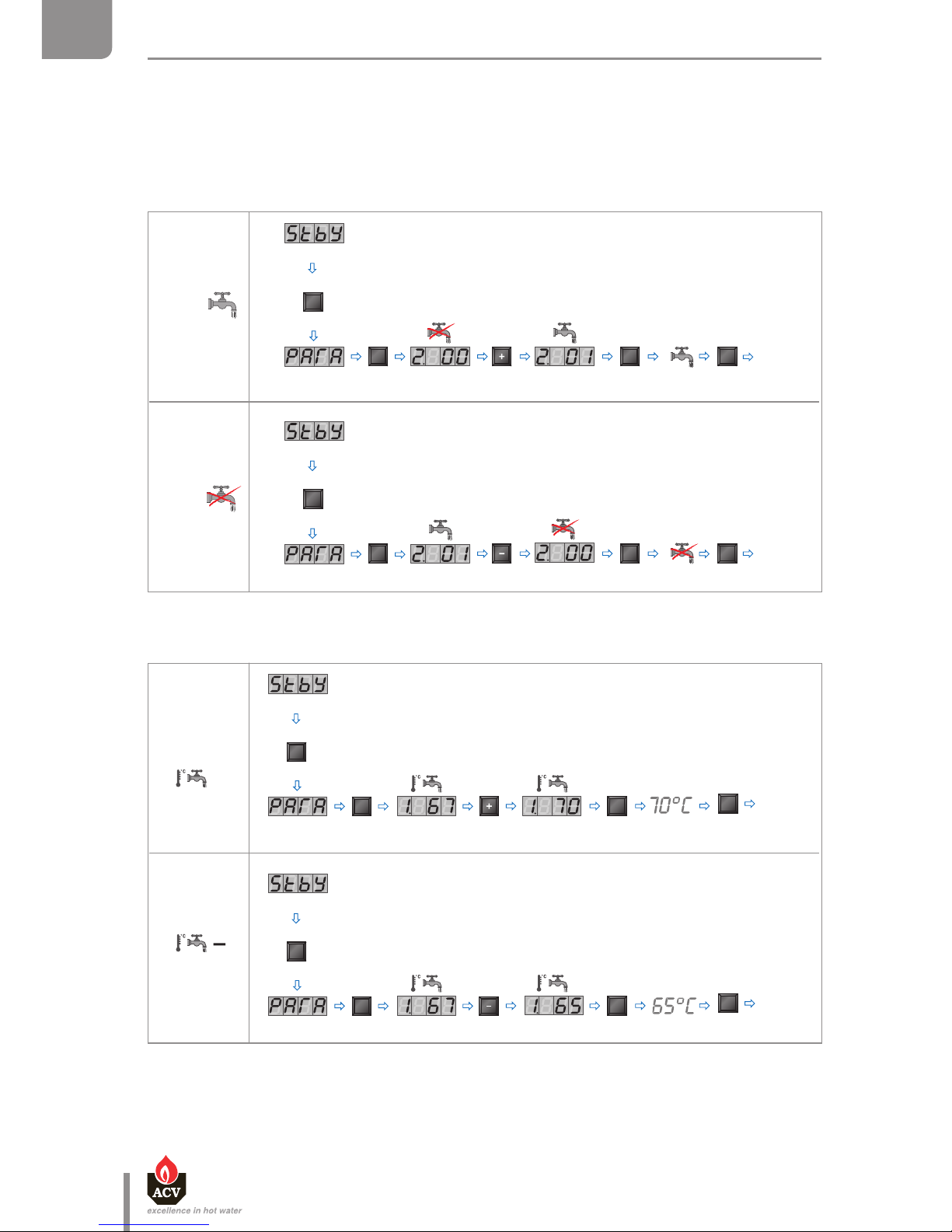
The end user is allowed to perform some of the settings: turn on/o the domestic hot water (DHW-)/
heating function and dene the required temperature of the DHW/heating circuits.
Using a special maintenance code to be entered in the MCBA interface, the qualied installers can
access parameters and therefore adjust the boiler settings to specic requirements. The parameters
are normally factory-preset for all normal applications.
Page 8
en
8
Heat Master TC : 6 64Y6800 • A
EN
FR
NL
ES
IT
DE
PL
RU
USER'S GUIDE
→ Setting the required DHW temperature
DHW mode: When it is enabled through the MCBA, this mode allows to dene the DHW temperature
set-point of the hot water preparation tank. The maximum authorized DHW temperature is 75°C.
→ Enable / disable the DHW mode
2 X
1 X
Mode
Step
X
Mode
Store
1 X
1 X
Stand
by
mode
Stand by mode
ON
2 X
1 X
Mode
Step
2 X
Mode
Store
Stand
by
mode
OFF
2
Stand by mode
1
X
1
X
Mode
Step
2
X
Mode
Store
1
X
Stand
by
mode
1
X
1
X
Mode
Step
2
X
Mode
Store
1
X
Stand
by
mode
+
Stand by mode
Stand by mode
Page 9

en
9
Heat Master TC : 6 64Y6800 • A
EN
FR
NL
ES
IT
DE
PL
RU
USER'S GUIDE
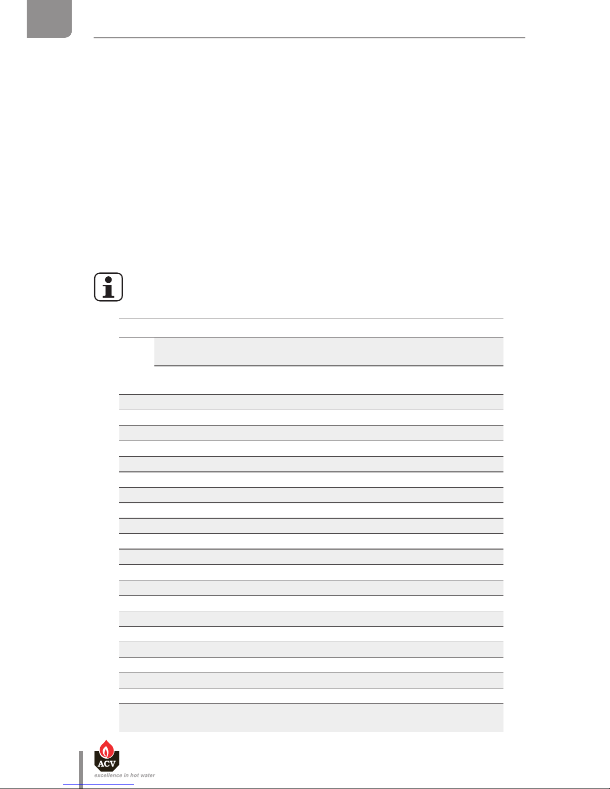
→ Setting the required heating temperature
Central Heating Mode: When it is enabled through the MCBA, this mode allows to dene the
primary circuit temperature set-point for the heating function. The maximum authorized temperature
for the circuit is 90°C.
→ Enable / disable the central heating mode
3 X
1 X
Mode
Step
2 X
Mode
Store
1 X
Stand
by
mode
3 X
1 X
Mode
Step
2 X
Mode
Store
1 X
Stand
by
mode
ON
OFF
Stand by mode
Stand by mode
4
X
1
X
Mode
Step
2
X
Mode
Store
1
X
Stand
by
mode
4
X
1
X
Mode
Step
2
X
Mode
Store
1
X
Stand
by
mode
+
Stand by mode
Stand by mode
Page 10
en
10
Heat Master TC : 6 64Y6800 • A
EN
FR
NL
ES
IT
DE
PL
RU
APPLIANCE DESCRIPTION
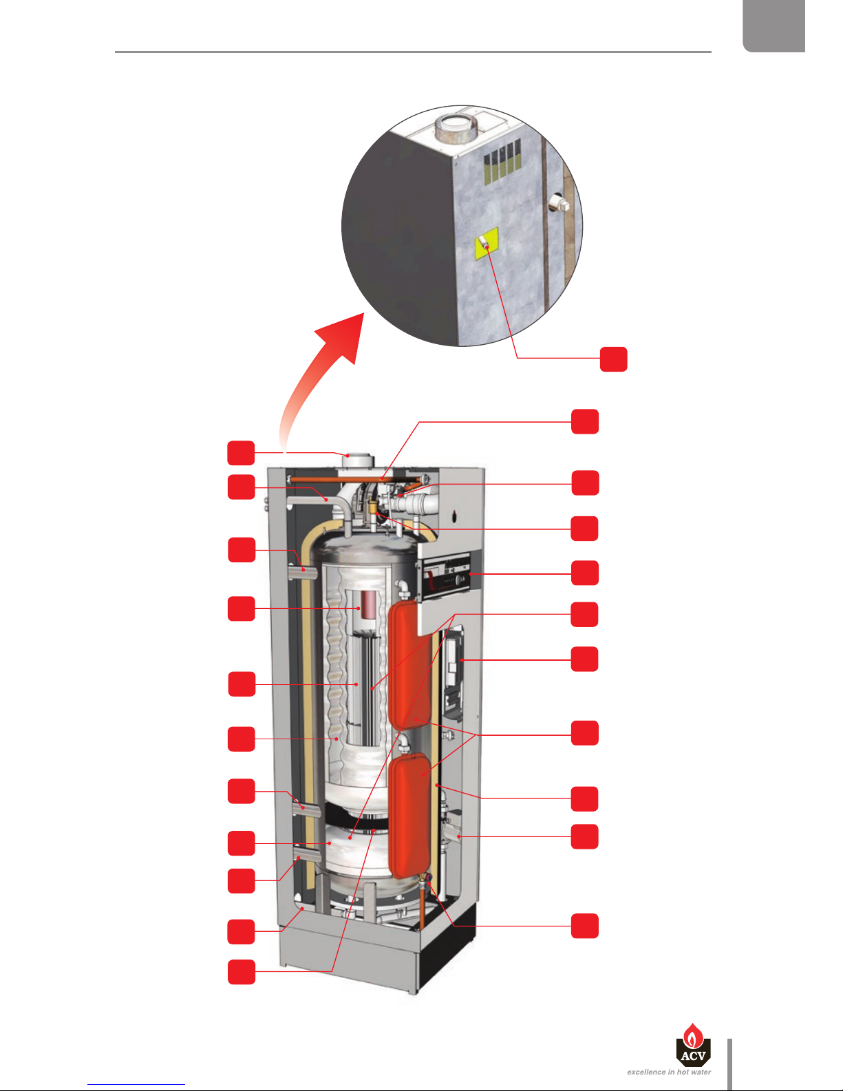
The HeatMaster® TC series combines ACV's "Tank-in-Tank" concept with a double primary circuit to
reach the high performance of a TOTAL CONDENSATION, double-circuit boiler.
The HeatMaster® models are always delivered with an ACV air/gas premix BG 2000-M burner, with low
NOx emissions. During operation, the burner starts automatically as soon as the boiler temperature
gets lower than the preset temperature and stops as soon as the preset temperature is reached.
The appliance is tted with a built-in low water pressure switch that blocks the appliance when the
pressure is not sucient: the heating circuit must be kept under water pressure (at least 1 bar). If the
pressure reading on the pressure gauge is below 0.5 bar, the pressure switch stops the boiler until the
pressure is higher than 0.8 bar again.
The HeatMaster® TC series is tted with a built-in frost protection: as soon as the boiler temperature
[NTC1 sensor] drops below 7°C, the central heating pump is enabled. As soon as the NTC1 temperature
is lower than 3°C, the burner ignites until the temperature exceeds 10°C. The heating pump continues
to run for 10 minutes.
If an outdoor temperature sensor is connected, the pump is started whenever the outdoor temperature
drops below the preset temperature. To allow the boiler to protect the system against frost, all the
radiator and convector valves should be fully open.
Depending on the model, the HeatMaster® TC are equipped with a high efficiency
charging pump, or with a standard charging pump.
Detail of components
1.
80/125 mm concentric flue pipe connection, that can be transformed into
two 80/80 mm pipes (HM 25 / 35 / 45 TC)
100/150 mm concentric flue pipe connection, that can be transformed into
two 100/100 mm pipes (HM 85/ 120 TC)
2. Domestic hot water outlet
3. Heating circuit outlet
4. Combustion chamber
5. Stainless steel heat exchanger
6. Stainless steel "Tank in Tank" hot water production tank
7. Auxiliary heating circulation loop
8. Indirect water pre-heater
9. Heating circuit inlet
10. Cold water inlet
11. Primary circuit separation disc
12. Gas connection tube
13. Modulating AIR/GAS premix burner
14. Air bleed valve
15. Control panel
16. Heating circuit
17. Electronic board
18. Primary circuit expansion vessel(s) (HM 70 / 85 / 120 TC)
19. Hard expanded polyurethane foam insulation
20. Boiler charging pump (auxiliary circulation loop)
21a. Safety valve (3 bar) (HM TC equipped with a standard pump)
21b Connection + safety valve (3bar) to be installed (HM TC equipped with a
high efficiency pump)
Page 11
21b
12
13
14
15
16
17
18
19
20
21a
11
10
9
8
7
6
5
4
3
2
1
en
11
Heat Master TC : 6 64Y6800 • A
EN
FR
NL
ES
IT
DE
PL
RU
APPLIANCE DESCRIPTION
Page 12

en
12
Heat Master TC : 6 64Y6800 • A
EN
FR
NL
ES
IT
DE
PL
RU
APPLIANCE DESCRIPTION
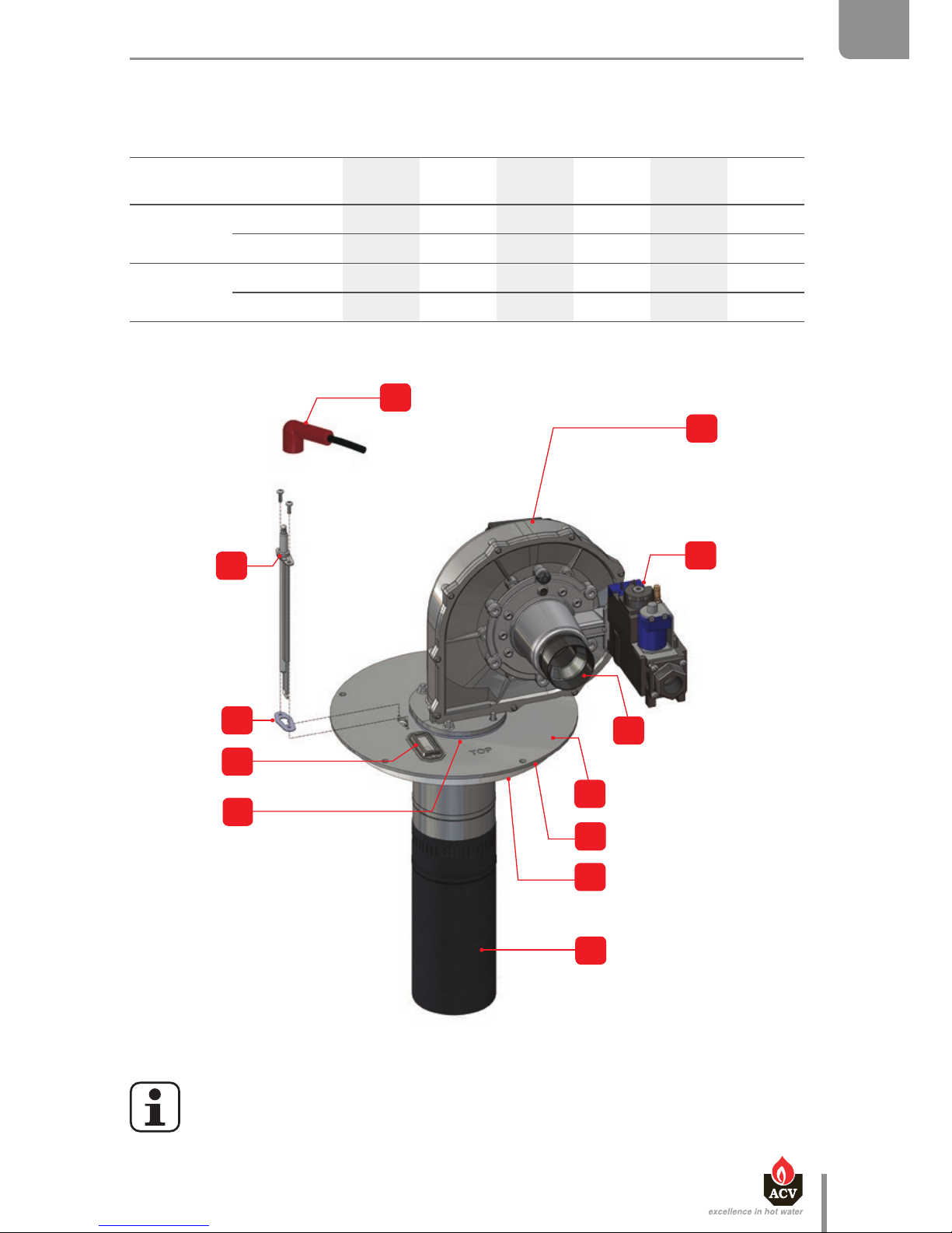
BURNER DESCRIPTION
ACV AIR/GAS premix BG 2000-M burner
Main components of the burner:
- Variable speed fan
- Automatic ignition and ame detection system
- Gas valve/venturi set specially developed for low NOX air/gas premix burners.
The power continually adjusts to demand, which greatly improves the general eciency of the heating
and DHW systems. The burner tube is covered with a metal ber element (NIT) which, besides its
remarkable heat exchange capacity, guarantees longer burner life.
The controller guarantees that the gas pressure at the gas valve outlet is kept equal to the absolute air
pressure at the venturi inlet, corrected by the oset adjustment value. The fan draws the combustion
air through the venturi, whose neck is connected to the gas valve outlet. The pressure dierential
created at the venturi neck by the air ow rate generates a gas intake proportional to its amount (the
higher the air ow rate, the higher the pressure dierential, and therefore the gas intake). The air/gas
mix is then introduced into the burner via the fan.
Detail of components
1.
Fan
2.
Gas valve
3.
Venturi
4.
Burner chamber plate flange
5.
Heat exchanger seal
6.
Insulation
7.
Burner tube
8.
Fan seal
9.
Flame sight glass
10.
Electrode seal
11.
Electrode
12.
Ignition cable (part of the electrode assembly in the HM 45 TC)
Page 13
12
1
2
3
4
5
6
7
8
10
11
9
en
13
Heat Master TC : 6 64Y6800 • A
EN
FR
NL
ES
IT
DE
PL
RU
TECHNICAL CHARACTERISTICS
BURNER CHARACTERISTICS
HM 25 TC HM 35 TC HM 45 TC HM 70 TC HM 85 TC HM 120 TC
Gas type
Nat. gas
Propane
Nat. gas
Propane
Nat. gas
Propane
Nat. gas
Propane
Nat. gas
Propane
Nat. gas
Propane
Min fan speed
Nat. gas rpm 1500 2000 1600 1900 1900 1300
Propane rpm 1500 2400 1800 1900 1900 1300
Max. fan speed
Nat. gas rpm 6500 6300 6800 4900 6500 5300
Propane rpm 6100 6500 6900 4500 6000 5300
• The figure shows the HM 120 TC burner. The HM 25 / 35 / 45 / 70 / 85 TC burner
configuration is slightly different.
Page 14

en
14
Heat Master TC : 6 64Y6800 • A
EN
FR
NL
ES
IT
DE
PL
RU
TECHNICAL CHARACTERISTICS
SINGLE GAS CATEGORIES All models
Gas type G20 G25 G20 / G25 G25.1 G31 G30
Pressure (mbar) 20 25 20-25 25 30 37 50 30 50
Country
code
Category
AT
I
2H
I
3P
I
3B/P
BE
I
2E(S)
*
I
2E(R)
**
I
3P
CH
I
2H
I
3P
I
3B/P
CY
I
2H
I
3B/P
CZ
I
2H
I
3P
DE
I
2E
I
2ELL
I
3P
I
3B/P
DK
I
2H
I
3B/P
EE
I
2H
I
3B/P
ES
I
2H
I
3P
FR
I
2Er
I
3P
I
3B/P
GB
I
2H
I
3P
I
3B/P
GR
I
2H
I
3P
HR
I
2H
I
3P
I
3B/P
HU
I2
HS
I
3B/P
* HM 25 / 35 / 45 / 70 TC
** HM 85 / 120 TC
Page 15

en
15
Heat Master TC : 6 64Y6800 • A
EN
FR
NL
ES
IT
DE
PL
RU
TECHNICAL CHARACTERISTICS
Gas type G20 G25 G20 / G25 G25.1 G31 G30
Pressure (mbar) 20 25 20-25 25 30 37 50 30 50
Country
code
Category
IE
I
2H
I
3P
IT
I
2H
I
3P
I
3B/P
LT
I
2H
I
3P
I
3B/P
LU
I
2E
I
3B/P
LV
I
2H
NL
I
2L
I
3P
I
3B/P
NO
I
2H
I
3B/P
PL
I
2E
I
3P
I
3B/P
PT
I
2H
I
3P
RO
I
2H
I
2E
I
3P
I
3B/P
SE
I
2H
I
3B/P
SI
I
2H
I
3P
I
3B/P
SK
I
2H
I
3P
I
3B/P
TR
I
2H
I
3B/P
Page 16

en
16
Heat Master TC : 6 64Y6800 • A
EN
FR
NL
ES
IT
DE
PL
RU
TECHNICAL CHARACTERISTICS
DOUBLE GAS CATEGORIES HM 70 / 85 / 120 TC only
Gas type G20 G25
G20
G25
G31 G30
G30 G31
Pressure (mbar) 20 20 25
20
25
30 37 50 30 50
28 - 30
37
50
67
Country code Category
AT
II
2H3P
II
2H3B/P
CH
II
2H3P
II
2H3B/P
II
2H3+
CY
II
2H3B/P
II
2H3+
CZ
II
2H3P
II
2H3+
DE
II
2E3B/P
II
2ELL3B/P
DK
II
2H3B/P
EE
II
2H3B/P
ES
II
2H3P
FI
II
2H3B/P
FR
II
2Er3P
II
2E+3+
GB
II
2H3P
II
2H3+
GR
II
2H3P
II
2H3+
HR
II
2H3P
II
2H3B/P
HU
II
2H3B/P
IE
II
2H3P
II
2H3+
IT
II
2H3P
II
2H3B/P
II
2H3+
Page 17

en
17
Heat Master TC : 6 64Y6800 • A
EN
FR
NL
ES
IT
DE
PL
RU
TECHNICAL CHARACTERISTICS
Gas type G20 G25
G20
G25
G31 G30
G30 G31
Pressure (mbar) 20 20 25
20
25
30 37 50 30 50
28 - 30
37
50
67
Country code Category
LT
II
2H3P
II
2H3B/P
II
2H3+
LU
II
2E3B/P
NL
II
2H3B/P
NO
II
2H3B/P
PL
II
2E3B/P
PT
II
2H3P
II
2H3+
RO
II
2H3P
II
2H3B/P
II
2E3B/P
SE
II
2H3B/P
SI
II
2H3P
II
2H3B/P
II
2H3+
SK
II
2H3P
II
2H3B/P
II
2H3+
TR
II
2H3B/P
Page 18

en
18
Heat Master TC : 6 64Y6800 • A
EN
FR
NL
ES
IT
DE
PL
RU
TECHNICAL CHARACTERISTICS
COMBUSTION CHARACTERISTICS
Main Characteristics
HM 25 TC HM 35 TC HM 45 TC
G20/G25 G31 G20/G25 G31 G20/G25 G31
Input (PCI)
max kW 25.0 25.0 34.9/34.5 31.0 45.6 40.7
min kW 4.7 5 9.8/10.6 10.0 9.0/9.6 8.8
Output at 100%
(80/60°C) kW 24.3 24.3 34.0/33.6 30,2 44.7 39.9
(50/30°C) kW — — — — 47.4 42,3
Eciency at 100%
(80/60°C) % 97.3 97.3 97.3 97.3 98.0 98.0
(50/30°C) % — — — — 103.9 103.9
Eciency at 30% load (EN677) % 108.9 108.9 108.9 108.9 108.9 108.9
Combustion
eciency
at 100% % 98.2 98.2 98.2 98.2 97.9 98.2
NOx (Class 5)
Max. output mg/kWh 74 81 59 72 42 42
Min. output mg/kWh 33 31 33 31 24 24
Weighted mg/kWh 53 53 41 41 38 38
CO
Max. output mg/kWh 44 55,3 89.1/103.9 119.6 61.3/82.2 184
Min. output mg/kWh 23 9 4.6/17.1 20.9 5.9 4.8
CO
2
Max. output %CO29.3 10.7 9.3 10.5 8.9/9.16 11.2
Min. output %CO
2
8.8 10.7 8.4/9.1 9.8 8.7 9.5
Max gas ow rate
G20/G25
20 mbar m³/h 2.64 3.75 4.8
25 mbar m³/h 2.64 4.25 5.7
Max. gas ow rate
G31
30/37/50 mbar Kg/h 2.0 2.0 2.7
30/37/50 mbar m³/h 1.26 1.26 1.66
Standby loss
T = 45 K
W 187 187 187 187 187 187
T = 30 K
W 113 113 113 113 113 113
Page 19
en
19
Heat Master TC : 6 64Y6800 • A
EN
FR
NL
ES
IT
DE
PL
RU
TECHNICAL CHARACTERISTICS
Main Characteristics
HM 70 TC HM 85 TC HM 120 TC
G20/G25 G31 G20/G25 G31 G20/G25 G31
Input (PCI)
max. kW 69.9 69.9 85.9/85.0 83.6 115/114.6 115
min. kW 24.5 24.5 24.5 24.5 23.2 24.8
Output at 100%
(80/60°C) kW 68.0 68.0 82,.9 83.6 111.6 111.6
(50/30°C) kW — — — — 121.7 121.7
Eciency at 100%
(80/60°C) % 97.3 97.3 97.5 97.5 97.1 97.1
(50/30°C) % — — — — 105.8 105.8
Eciency at 30% load (EN677) % 109.0 109.0 108.4 108.4 108.8 108.8
Combustion
eciency
at 100% % 98.1 98.1 98.0 98.0 97.5 97.5
NOx (Class 5)
Max. output mg/kWh 52 85 72/65 85 57/56 49
Min. output mg/kWh 27 27 27 27 10 42
Weighted mg/kWh 28 28 44 44 56 56
CO
Max. output mg/kWh 56.3 90.0 74.4/118.7 98.8 119.2/121.4 103.0
Min. output mg/kWh 2.0 45.0 5.9/55.0 53.8 7.6/61.8 12.8
CO
2
Max. output %CO29.1 10.9 9.3 10.9 9.3 10.2
Min. output %CO
2
8.6 10.0 8.6 8.5/10.0 8.4 10.0
Max gas ow rate
G20/G25
20 mbar m³/h 7.4 9.0 12.2
25 mbar m³/h 8.6 10.5 14.2
Max. gas ow rate
G31
30/37/50 mbar Kg/h 5.43 5.6 7.5
30/37/50 mbar m³/h 2.86 3.4 4.69
Standby loss
T = 45 K
W 342 342 342 342 342 342
T = 30 K
W 206 206 206 206 206 206
Page 20

en
20
Heat Master TC : 6 64Y6800 • A
EN
FR
NL
ES
IT
DE
PL
RU
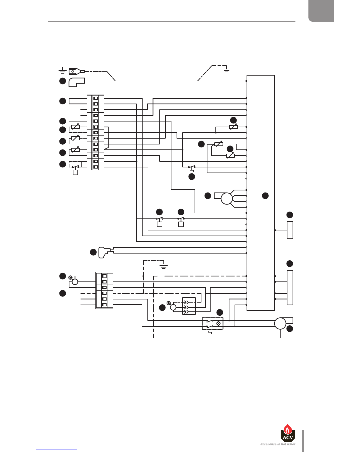
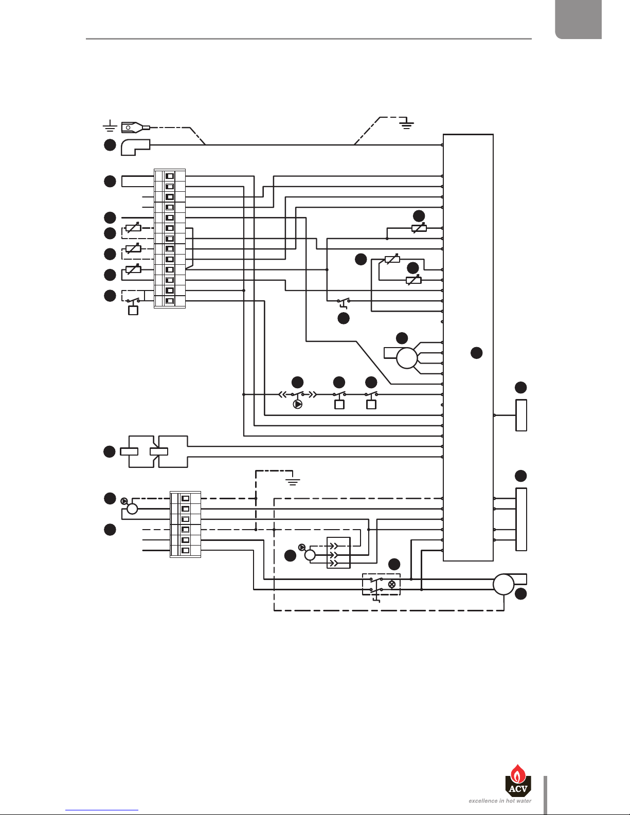
ELECTRICAL CHARACTERISTICS HM TC EQUIPPED WITH A
STANDARD CHARGING PUMP
TECHNICAL CHARACTERISTICS
Description
1. 230 V power supply plug
2. ON/OFF master switch
3. Charging pump
4. Heating pump (option)
5. Gas valve rectifier
6. 230 Volt-24 Volt transformer
7. MCB A
8. Display
9. Low water pressure switch
10. Burner PWM plug
11. Summer/winter switch
12. NTC1 flow sensor
13. NTC2 return sensor
14. NTC5 flue gas temperature sensor
15. Room thermostat (option)
16. NTC3 DHW sensor
17. NTC4 outdoor temperature sensor (option)
18. NTC6 flow sensor for second heating circuit (option)
19. Positive terminal of the ionization current
20. RAM high limit thermostat (option)
21. Ignition and ionization cable
22. 230 Volt burner power supply (HeatMaster® 70 / 85 TC)
23. Gas pressure switch (HeatMaster® 70 / 85 TC)
The ionization current is measured between terminal 19 and ground.
Main Characteristics
HM 25 / 35 TC HM 70 / 85 TC
Rated voltage V~ 230 230
Rated frequency Hz 50 50
Rated current (fuse) A 6 6
Electrical consumption W 176 220 / 230
Input intensity A 0.8 1
IP Class IP 30 IP 30
Page 21
Br
B
B
V
W
Y/Gr
B
Br
G
R
V
O
R
W
V
R
Bk
B
Bk
O
Br
R
Br
B
R
Br
Bk
Bk
O
Br
B
R
Bk
230V ~ 50Hz
Br
B
Br
B
B
Br
G
R
V
BkB
RB
B
V
G
O
B
BUS B
BUS A
W
Br
Bk
O
Br
R
Bk
Br
G
R
Br
B
Y/Gr Y/Gr
Y/Gr
B
W
L
N
PE
Y/Gr
B
Br
B
B
B
Y/Gr
X12.
P P
X11.
L1
N
PE
M
M
1 2 3 4 5 6 7 8 9 10 11 12 13
1 2 3 4 5 6
X1.6
X1.5
X1.4
X1.3
X1.2
X7
X10.6
X10.7
X10.1
X10.3
X1.1
X2.12
X2.11
X2.10
X2.9
X2.8
X2.7
X2.6
X2.5
X2.4
X2.3
X2.2
X2.1
X3.6
X3.5
X3.4
X3.3
X3.2
X3.1
X4.3
X4.2
X4.1
X5.4
X5.3
X5.2
X5.1
t
V OG
22
23
21
20
19
18
17
16
15
14
13
12
11
10
9
8
7
6
5
4
3
2
1
B. Blue
Bk. Black
Br. Brown
G. Grey
O. Orange
R. Red
V. Violet
W. White
Y/Gr. Yellow/Green
en
21
Heat Master TC : 6 64Y6800 • A
EN
FR
NL
ES
IT
DE
PL
RU
TECHNICAL CHARACTERISTICS
Page 22

en
22
Heat Master TC : 6 64Y6800 • A
EN
FR
NL
ES
IT
DE
PL
RU
TECHNICAL CHARACTERISTICS
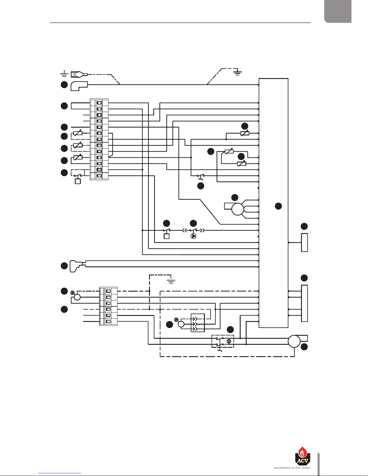
Description
1. 230 V power supply plug
2. ON/OFF master switch
3. Charging pump (high efficiency)
4. Heating pump (option)
5. Gas valve rectifier
6. 230 Volt-24 Volt transformer
7. MCB A
8. Display
9. Low water pressure switch
10. Burner PWM plug
11. Summer/winter switch
12. NTC1 flow sensor
13. NTC2 return sensor
14. NTC5 flue gas temperature sensor
15. Room thermostat (option)
16. NTC3 DHW sensor
17. NTC4 outdoor temperature sensor (option)
18. NTC6 flow sensor for second heating circuit (option)
19. Positive terminal of the ionization current
20. RAM high limit thermostat (option)
21. Ignition and ionization cable
22. 230 Volt burner power supply
The ionization current is measured between terminal 19 and ground.
ELECTRICAL CHARACTERISTICS HM TC < 70 KW EQUIPPED WITH A
HIGH EFFICIENCY PUMP
Main Characteristics
HM TC < 70 kW
Rated voltage V~ 230
Rated frequency Hz 50
Rated current (fuse) A 6
Electrical consumption W 160
Input intensity A 0.7
IP Class IP 30
Page 23
B. Blue
Bk. Black
Br. Brown
G. Grey
O. Orange
R. Red
V. Violet
W. White
Y/Gr. Yellow/Green
Br
B
B
V
W
Y/Gr
B
Br
G
R
V
O
R
W
V
R
Bk
B
Bk
O
Br
R
Br
B
R
Br
Bk
Bk
O
Br
B
R
Bk
230V ~ 50H
z
Br
B
Br
B
G
R
V
BkB
RB
B
V
G
O
B
BUS B
BUS A
W
Br
Bk
O
Br
R
Bk
Br
G
R
Br
B
Y/Gr Y/Gr
Y/Gr
B
W
L
N
PE
Y/Gr
B
Br
B
B
B
Y/Gr
X12.
P
X11.
L1
N
PE
M
M
12345678910111213
123456
X1.6
X1.5
X1.4
X1.3
X1.2
X7
X10.6
X10.7
X10.1
X10.3
X1.1
X2.12
X2.11
X2.10
X2.9
X2.8
X2.7
X2.6
X2.5
X2.4
X2.3
X2.2
X2.1
X3.6
X3.5
X3.4
X3.3
X3.2
X3.1
X4.3
X4.2
X4.1
X5.4
X5.3
X5.2
X5.1
t
VOG
22
3
21
20
19
18
17
16
15
14
13
12
11
10
9
8
7
6
4
3
2
1
B4S3
B
Br
5
en
23
Heat Master TC : 6 64Y6800 • A
EN
FR
NL
ES
IT
DE
PL
RU
TECHNICAL CHARACTERISTICS
Page 24

en
24
Heat Master TC : 6 64Y6800 • A
EN
FR
NL
ES
IT
DE
PL
RU
TECHNICAL CHARACTERISTICS
Description
1. 230 V power supply plug
2. ON/OFF master switch
3. Charging pump (high efficiency)
4. Heating pump (option)
5. Gas valve rectifier
6. 230 Volt-24 Volt transformer
7. MCB A
8. Display
9. Low water pressure switch
10. Burner PWM plug
11. Summer/winter switch
12. NTC1 flow sensor
13. NTC2 return sensor
14. NTC5 flue gas temperature sensor
15. Room thermostat (option)
16. NTC3 DHW sensor
17. NTC4 outdoor temperature sensor (option)
18. NTC6 flow sensor for second heating circuit (option)
19. Positive terminal of the ionization current
20. RAM high limit thermostat (option)
21. Ignition and ionization cable
22. 230 Volt burner power supply
23. Gas pressure switch
The ionization current is measured between terminal 19 and ground.
ELECTRICAL CHARACTERISTICS HM TC ≥ 70 KW EQUIPPED WITH A
HIGH EFFICIENCY PUMP.
Main Characteristics
HM TC ≥ 70 kW
Rated voltage V~ 230
Rated frequency Hz 50
Rated current (fuse) A 6
Electrical consumption W 380
Input intensity A 1.7
IP Class IP 30
Page 25
Br
B
B
V
W
Y/Gr
B
Br
G
R
V
O
R
W
V
R
Bk
B
Bk
O
Br
R
Br
B
R
Br
Bk
Bk
O
Br
B
R
Bk
230V ~ 50H
z
Br
B
Br
B
B
Br
G
R
V
BkB
RB
B
V
G
O
B
BUS B
BUS A
W
Br
Bk
O
Br
R
Bk
Br
G
R
Br
B
Y/Gr Y/Gr
Y/Gr
B
W
L
N
PE
Y/Gr
B
Br
B
B
B
Y/Gr
X12.
PP
X11.
L1
N
PE
M
M
12345678910111213
123456
X1.6
X1.5
X1.4
X1.3
X1.2
X7
X10.6
X10.7
X10.1
X10.3
X1.1
X2.12
X2.11
X2.10
X2.9
X2.8
X2.7
X2.6
X2.5
X2.4
X2.3
X2.2
X2.1
X3.6
X3.5
X3.4
X3.3
X3.2
X3.1
X4.3
X4.2
X4.1
X5.4
X5.3
X5.2
X5.1
t
VOOG
22
233
21
20
19
18
17
16
15
14
13
12
11
10
9
8
7
6
5
4
3
2
1
S3B4
en
25
Heat Master TC : 6 64Y6800 • A
EN
FR
NL
ES
IT
DE
PL
RU
TECHNICAL CHARACTERISTICS
B. Blue
Bk. Black
Br. Brown
G. Grey
O. Orange
R. Red
V. Violet
W. White
Y/Gr. Yellow/Green
Page 26
bar
2
1O3
4
A
B
H
G
C
F
O
N
L
K
J
I
M
D
E
en
26
Heat Master TC : 6 64Y6800 • A
EN
FR
NL
ES
IT
DE
PL
RU
TECHNICAL CHARACTERISTICS
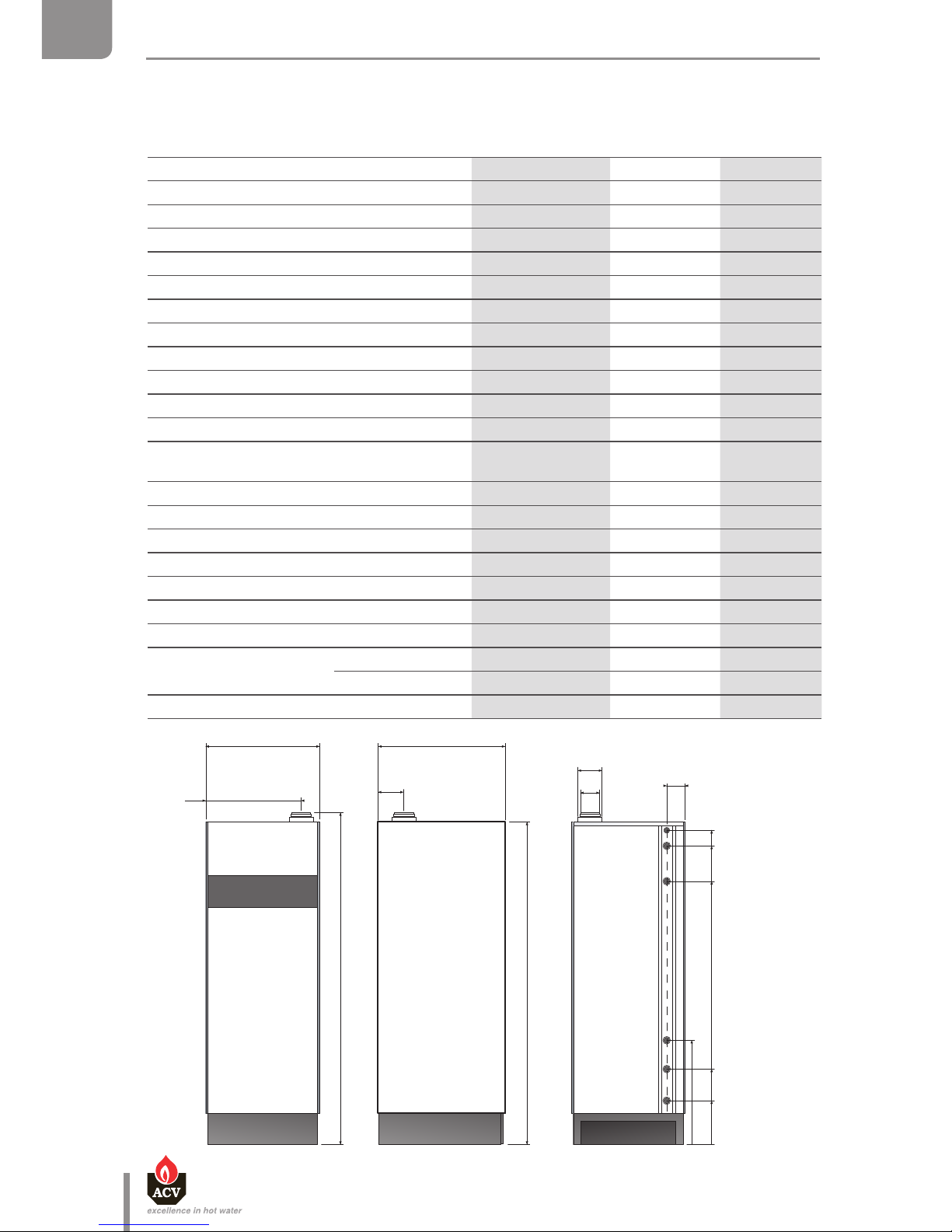
DIMENSIONS
Boiler Dimensions HM 25 / 35 / 45 TC HM 70 / 85 TC HM 120 TC
A = Height mm 1730 2165 2220
B = Width mm 600 690 690
C = Depth mm 670 725 725
D mm 80 100 100
E mm 125 150 150
F mm 140 160 160
G mm 1705 2115 2170
H mm 500 580 580
I mm 110 125 125
J = height at gas valve mm 1660 2070 2125
K = height at DHW outlet mm 1560 1975 2030
K = height at primary circuit outlet mm 1365 1695 1750
M = height at auxiliary circulation
loop connection
mm 685 740
N = height at primary circuit inlet mm 405 485 540
O = height at DHW circuit inlet mm 220 260 315
Heating Connection [F] Ø 1" 1”1/2 1"1/2
DHW Connection [M] Ø 1” 1” 1”
Gas connection [M] Ø 3/4" 3/4" 3/4"
min. ∅ of ue pipe mm 80 100 100
Volume of the combustion chamber L 4,0 19,3 19,3
Combustion chamber
Height mm 210 435 435
dia. mm 161 236 236
Drained weight Kg 174 284 319
Page 27
B C
bar
2
1O3
4
A
D
en
27
Heat Master TC : 6 64Y6800 • A
EN
FR
NL
ES
IT
DE
PL
RU
TECHNICAL CHARACTERISTICS
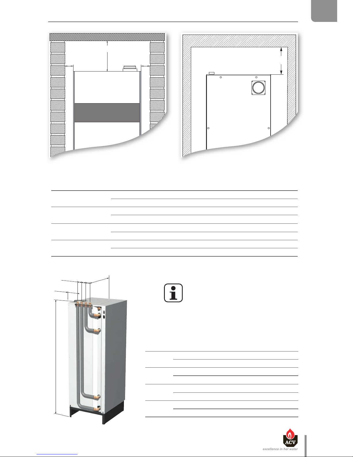
Boiler Clearance HeatMaster® 25 / 35 / 45 / 70 / 85 / 120 TC
A (mm)
Recommended 400
Minimum 300
B (mm)
Recommended 800
Minimum 600
C (mm)
Recommended 400
Minimum 250
D (mm)
Recommended 600
Minimum 400
Front view
View from the top
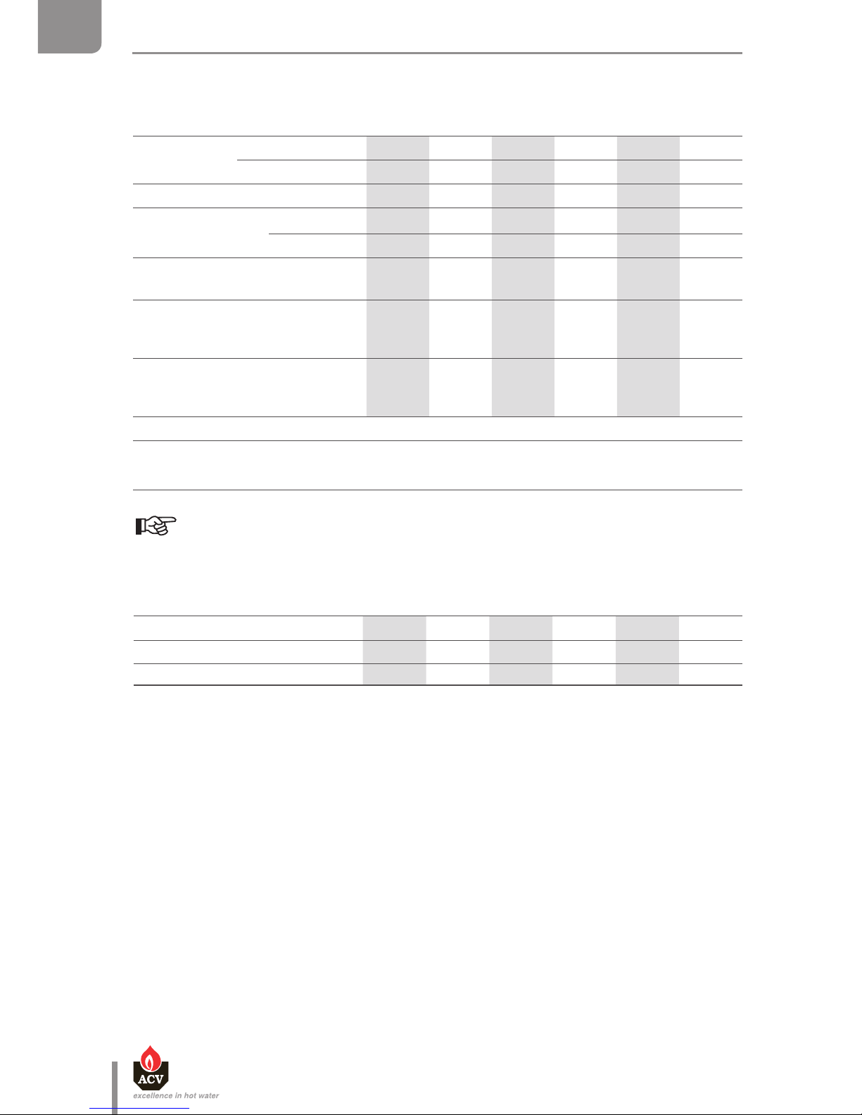
1736
3 x 65
180
690
"Easy Fit" kit - only for
HeatMaster® 25 / 35 / 45 TC
Clearance with
Easy Fit kit
HeatMaster® 25 / 35 / 45 TC
A (mm)
Recommended 400
Minimum 300
B (mm)
Recommended 400
Minimum 300
C (mm)
Recommended 400
Minimum 250
D (mm)
Recommended 600
Minimum 400
Page 28
en
28
Heat Master TC : 6 64Y6800 • A
EN
FR
NL
ES
IT
DE
PL
RU
TECHNICAL CHARACTERISTICS
CHIMNEY CONNECTION CHARACTERISTICS
Flue pipe connection types
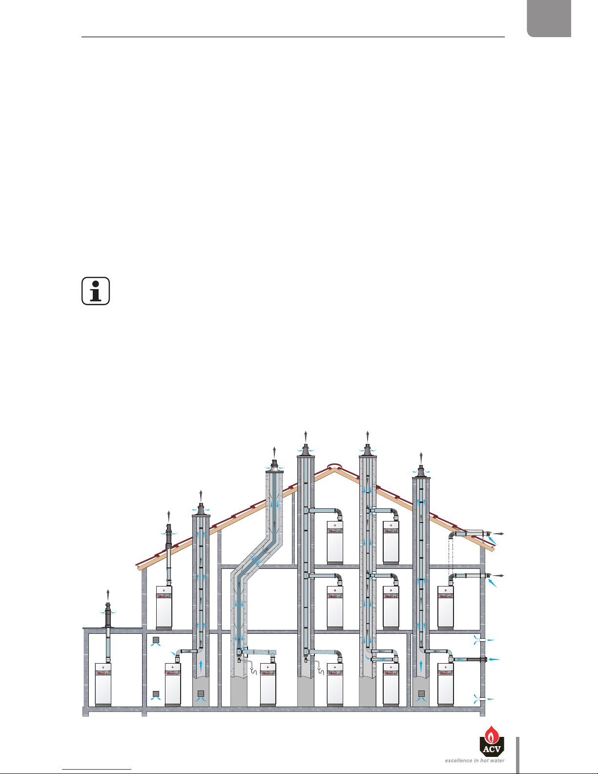
C13 : Connection using pipes tted with a horizontal terminal that simultaneously takes in
combustion air for the burner and discharges combustion products outside through
openings that are either concentric or close enough together to be subjected to similar
wind conditions
C33 : Connection using pipes tted with a vertical terminal that simultaneously takes in fresh
air for the burner and discharges combustion products outside through openings that are
either concentric or close enough together to be subjected to similar wind conditions
C43 : Connection using two pipes to a collective duct system serving more than one appliance;
this system of collective ducts features two pipes connected to a terminal unit that
simultaneously takes in fresh air for the burner and discharges the combustion products
outside through openings that are either concentric or close enough together to be
subjected to similar wind conditions.
C53 : Connection to separate ducts for supplying combustion air and discharging combustion
products; these ducts may end in zones with dierent pressure levels.
Boiler room ventilation
HM 25 TC HM 35 TC HM 45 TC HM 70 TC HM 85 TC HM 120 TC
Fresh air supply (B23 / B23P) m³/h 35.1 49.1 59.2 98.3 119.3 161.5
High ventilation dm² 0.8 1.1 1.5 2.1 2.6 3.6
Low ventilation dm² 0.8 1.1 1.5 2.1 2.6 3.6
It is mandatory to ventilate the boiler room. The high or low air vent opening dimensions
depend on the boiler power and the boiler room size. The table below provides indicative
values that need to be adapted according to local regulations in force.
Main Characteristics
HM 25 TC HM 35 TC HM 45 TC HM 70 TC HM 85 TC HM 120 TC
Air/flue pipe Ø
concentric mm
80/125 80/125 80/125 100/150 100/150 100/150
dual ow mm
80/80 80/80 80/80 100/100 100/100 100/100
Max. temp of ue gases °C
120 120 120 120 120 120
Flue gas temp. at
water temp. of
50/30°C °C
— — 40,9 — — 42,6
80/60°C °C
60 58 64 59 62 65
Max. allowed ue pipe
pressure drop
Pa
130 130 130 150 150 240
Max recommended length of concentric
ue pipe (corresponding length in
meters of straight pipes) *
65 33 22 25 16** 14**
Max recommended length of dual ow
(corresponding length in meters of
straight pipes) *
130 66 44 50 32** 28**
Available connection types B23 - B23P - C13 - C33 - C43 - C53*** - C63 - C83, C93
* See pages 30 and 31 to calculate the equivalent length in meters of straight pipes
** For superior length, please contact ACV.
*** A C53 connection of the HeatMaster 120 TC requires an optional accessory.
Page 29
C
13
C
33
C
53
C
43
C
43
C
43
C
33
B
23P
C
43
C
43
C
43
C
93
en
29
Heat Master TC : 6 64Y6800 • A
EN
FR
NL
ES
IT
DE
PL
RU
TECHNICAL CHARACTERISTICS
C63 : Type C boiler meant to be connected to a system for supplying combustion air and
discharging combustion products, that is approved and sold separately (Prohibited in
Belgium).
C83 : Connection using a single or double duct system. The system is made of a normal exhaust
ue duct that discharges the combustion products. The appliance is also connected
through a second duct tted with a terminal, that supplies the burner with fresh outdoor
air. [Only if the boiler is tted with an ACV premix BG 2000-S burner].
C93 : Connection using an individual system whose combustion product exhaust duct is
installed in an exhaust duct that is integral with the building. The appliance, the exhaust
duct and the terminal units are certied as an inseparable assembly.
B23 : Connection to an exhaust duct that discharges the combustion products outside the room
where it is installed, with the combustion air being drawn directly from the boiler room.
B23P : Connection to a combustion product exhaust system designed to operate with positive
pressure.
General remark
• Make sure to install a measurement unit on the flue pipe, in accordance with the
local regulation in force.
Page 30
en
30
Heat Master TC : 6 64Y6800 • A
EN
FR
NL
ES
IT
DE
PL
RU
TECHNICAL CHARACTERISTICS
CALCULATION OF THE FLUE PRESSURE DROP, OR OF THE
CORRESPONDING LENGTH IN METERS OF STRAIGHT PIPES
When connecting the flue pipes, make sure not to exceed the maximum flue pressure
drop value, or the corresponding maximum flue pipe length in meters of straight flue
pipes recommended for the product, otherwise the system pressure might decrease.
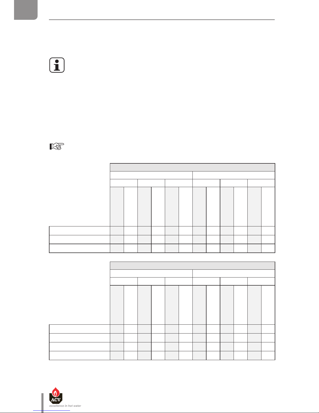
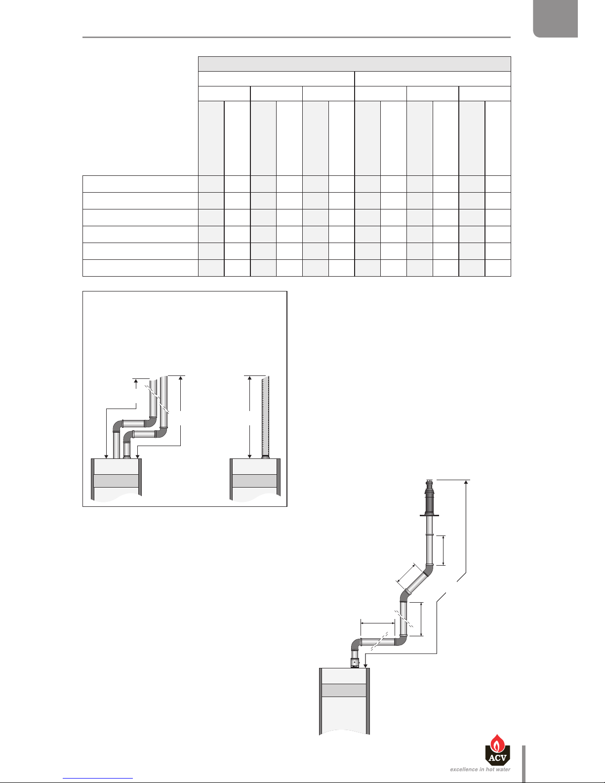
The ue pipe dimensions can be calculated using either method shown on the next page. These
two methods are equivalent. Please refer to the tables below indicating the pressure drop values, as
well as the corresponding length in meters of straight ue pipes, applied to each of the connection
components. Then compare the calculation result to the recommended maximum ue pressure drop
indicated in the table on page 28.
Tables of pressure drop values applied to the various elements for the calculation:
The following tables are based on ACV equipment and cannot be applied as a rule.
Distinct fresh air supply (L1)
Ø 80 mm Ø 100 mm
HM 25 TC HM 35 TC HM 45 TC HM 70 TC HM 8 5 TC HM 120 TC
Pa
corr. length in m
of straight pipes
Pa
corr. length in m
of straight pipes
Pa
corr. length in m
of straight pipes
Pa
corr. length in m
of straight pipes
Pa
corr. length in m
of straight pipes
Pa
corr. length in m
of straight pipes
1m straight pipe 1 1.0 2 1.0 3 1.0 4 1.0 6 1.0 11 1.0
90° elbow 1 1.0 2 1.0 4 1.3 8 2.0 12 2.0 21 1.9
45° elbow 1 1.0 1 0.5 2 0.7 3 0.8 5 0.8 10 0.9
Distinct ue gas exhaust (L2)
Ø 80 mm Ø 100 mm
HM 25 TC HM 35 TC HM 45 TC HM 70 TC HM 8 5 TC HM 120 TC
Pa
corr. length in m
of straight pipes
Pa
corr. length in m
of straight pipes
Pa
corr. length in m
of straight pipes
Pa
corr. length in m
of straight pipes
Pa
corr. length in m
of straight pipes
Pa
corr. length in m
of straight pipes
1m straight pipe 1 1.0 2 1.0 3 1.0 2 1.0 3 1.0 5 1.0
90° elbow 1 1.0 3 1.5 5 1.7 7 3.5 10 3.3 17 3.4
45° elbow 1 1.0 2 1.0 3 1.0 5 2.5 7 2.3 12 2.4
C53 adapter - - - - - - - - - - 43 2.5
L = Sum of the fresh air supply pipe length (L1) and of the flue gas pipe length (L2).
Page 31
en
31
Heat Master TC : 6 64Y6800 • A
EN
FR
NL
ES
IT
DE
PL
RU
TECHNICAL CHARACTERISTICS
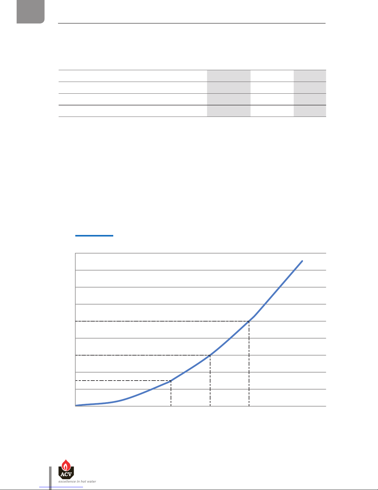
Concentric ue pipe
Ø 80 / 125 mm Ø 100 / 150 mm
HM 25 TC HM 35 TC HM 45 TC HM 70 TC HM 8 5 TC HM 120 TC
Pa
corr. length in m
of straight pipes
Pa
corr. length in m
of straight pipes
Pa
corr. length in m
of straight pipes
Pa
corr. length in m
of straight pipes
Pa
corr. length in m
of straight pipes
Pa
corr. length in m
of straight pipes
1m straight pipe 2 1.0 4 1.0 6 1.0 6 1.0 9 1.0 17 1.0
Pipe with measurement unit 2 1.0 3 0.8 4 0.7 3 0.5 4 0.4 7 0.4
90° elbow 3 1.5 6 1.5 10 1.7 14 2.3 21 2.3 38 2.2
45° elbow 2 1.0 3 0.8 5 0.8 8 1.3 12 1.3 22 1.3
Vertical terminal 18 9.0 35 8.8 58 9.7 22 3.7 32 3.6 59 3.5
Horizontal terminal 18 9.0 34 8.5 56 9.3 17 2.8 24 2.7 44 2.6
• Method 2:
a) Calculate the corresponding length in meters
of pipes (L) for the flue pipe assembly:
0,8 + (2 x 1,5) + (6 x 1,0) + (2 x 0,8) + 8,8 = 20,2
b) Compare the resulting value with the
recommended value (33 m of corresponding
length in meters of straight concentric flue
pipes). The flue pipe length is within the
recommended range.
Example of verification of the length of
concentric flue pipes for a HeatMaster 35 TC :
The methods are detailed through an example.
Figure 2 : The assembly is comprised of: 1 pipe
with a measurement unit + 2
x 90° elbows + 6
meters of straight pipes + 2
x 45° elbows + 1
vertical terminal.
• Method 1:
a) Calculate the pressure drop (Pa) of the whole
flue pipe assembly:
3 + (2 x 6) + (6 x 4) + (2 x 3) + 35 = 80
b) Compare the resulting value with the
recommended value (130 Pa).
The pressure drop for this flue pipe length is
within the recommended range.
L = corresponding length in meters
of straight ue pipes (1 m
straight pipe).
1000 mm
1000 mm
2000 mm
2000 mm
L
Fig. 2
The installer can check that the connection
complies (dual ow or concentric, g. 1) with
the recommended values (see tab. page 30
and 31) using one of the methods hereafter.
L = L1 + L2
dual ow Concentric
Fig. 1
L2
L1
L
Page 32
en
32
Heat Master TC : 6 64Y6800 • A
EN
FR
NL
ES
IT
DE
PL
RU
TECHNICAL CHARACTERISTICS
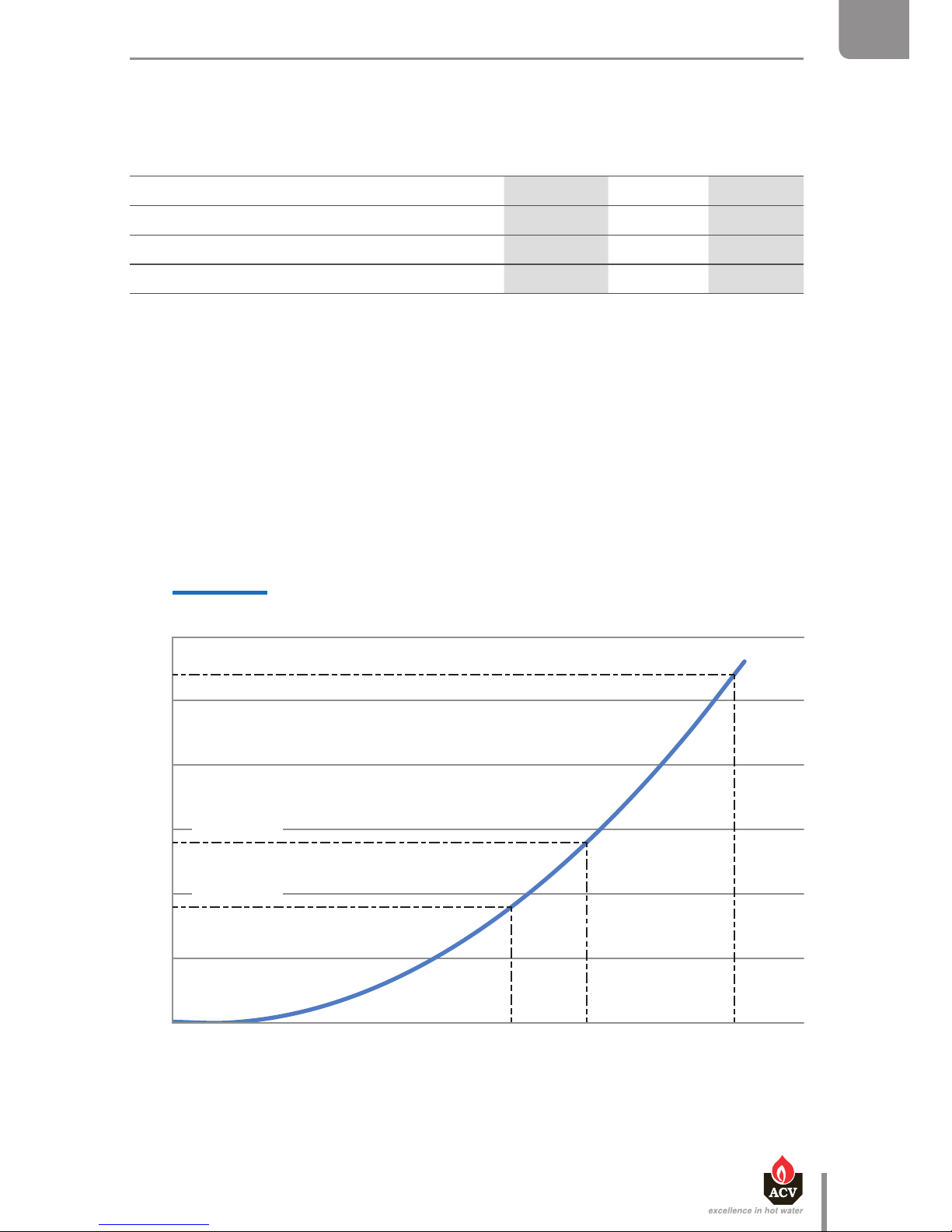
HeatMaster® 25 / 35 / 45 TC
0
2
4
6
8
10
12
14
16
18
0 500 1000 1500 2000 2500
3000
Perte de charge (mbar)
Débit (litres/heure)
Perte de charge (mbar)
HeatMaster® 45 TC
HeatMaster® 35 TC
HeatMaster® 25 TC
Pressure drop (mbar)
Flow rate (liters/hour)
HYDRAULIC CHARACTERISTICS
Main Characteristics
HM 25 TC HM 35 TC HM 45 TC
Capacity (DHW) L 100 100 100
Capacity (primary) L 100 100 100
Primary circuit expansion vessel volume L
—
Water pressure drop (primary circuit) (t = 20 K) mbar 3 6 10
Hydraulic pressure drop curve of the boiler
Page 33
en
33
Heat Master TC : 6 64Y6800 • A
EN
FR
NL
ES
IT
DE
PL
RU
TECHNICAL CHARACTERISTICS
0
5
10
15
20
25
30
0 100 0 20 00 3000 40 00 5000
6000
Pert e de charge (m bar)
Débit (litres/heur e)
Perte de charge (mbar)
HeatMaster® 120 TC
HeatMaster® 70 TC
HeatMaster® 85 TC
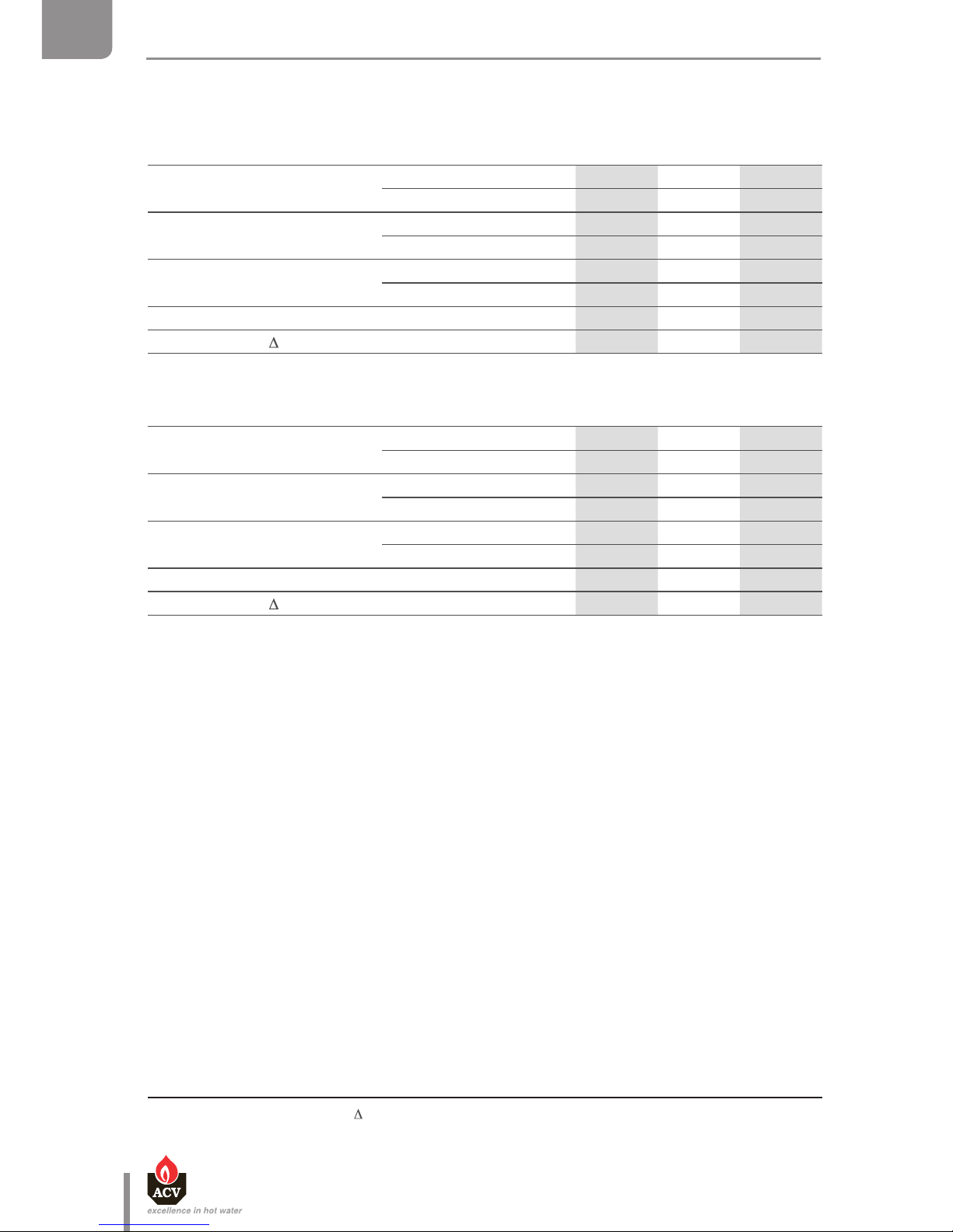
HeatMaster® 70 / 85 / 120 TC
Pressure drop (mbar)
Flow rate (liters/hour)
Hydraulic pressure drop curve of the boiler
Main Characteristics
HM 70 TC HM 85 TC HM 120 TC
Capacity (DHW) L 190 190 190
Capacity (primary) L 125 125 125
Primary circuit expansion vessel volume L 2 x 10 2 x 10 2 x 10
Water pressure drop (primary circuit) (t = 20 K) mbar 9 14 27
Page 34
en
34
Heat Master TC : 6 64Y6800 • A
EN
FR
NL
ES
IT
DE
PL
RU
TECHNICAL CHARACTERISTICS
DHW PERFORMANCE
Domestic hot water performance* (cold drink water at 10°C)
Operating conditions at 90°C
HM 25 TC HM 35 TC HM 45 TC
Constant ow at
40 °C [∆T = 30 K]
L/h
789 1104
1392
45 °C [∆T = 35 K]
L/h
676 946
1207
Peak ow at
40 °C [∆T = 30 K]
L/10’
382 440
498
45 °C [∆T = 35 K]
L/10’
331 370
409
Peak ow 1st hour at
40 °C [∆T = 30 K]
L/60’
1125 1360
1595
45 °C [∆T = 35 K]
L/60’
973 1159
1345
Reheat time from 10°C to 80°C min.
35 26
23
DHW eciency at T = 30 K %
105.4 105.4
103.1
Domestic hot water performance* (cold drink water at 10°C)
Operating conditions at 90°C
HM 70 TC HM 85 TC HM 120 TC
Constant ow at
40 °C [∆T = 30 K]
L/h
2234 2713 3402
45 °C [∆T = 35 K]
L/h
1915 2325 2928
Peak ow at
40 °C [∆T = 30 K]
L/10’
820 868 964
45 °C [∆T = 35 K]
L/10’
668 718 819
Peak ow 1st hour at
40 °C [∆T = 30 K]
L/60’
2761 3076 3706
45 °C [∆T = 35 K]
L/60’
2306 2513 3153
Reheat time from 10°C to 80°C min.
27 24 23
DHW eciency at T = 30 K %
103.9 103.9 102.2
* for DHW temperatures > 45°C ( T > 35K), please contact ACV
** For special applications, please contact ACV.
MAXIMUM OPERATING CONDITIONS
Maximum Service Pressure [DHW tank full of water]
- Primary circuit : .......................................................................................................................................... 3 bar
- DHW circuit : ........................................................................................................................................... 8,6 bar
- Recommended safety valve (central heating) : .................................................................... 3 bar
- Recommended safety valve (DHW) : .......................................................................................... 7 bar
Mains supply pressure
- Max 6 bar, without a pressure reducing valve being required (to avoid discharge of the safety pressure
valve)
Maximum Operating Conditions
- Maximum temperature (primary) : ................................................................................................ 90°C
- Maximum temperature (DHW) for the HM 25 / 35 / 45 / 70 TC** : ........................... 75°C
- Maximum temperature (DHW) for the HM 85 / 120 TC : ................................................. 90°C
Water Quality
See "Recommendations for the Prevention of Corrosion and Scaling".
Page 35
en
35
Heat Master TC : 6 64Y6800 • A
EN
FR
NL
ES
IT
DE
PL
RU
INSTALLATION
PACKAGE CONTENTS
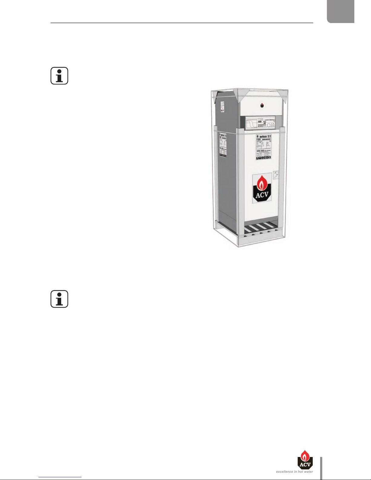
The HeatMaster® 25 / 35 / 45 / 70 / 85 / 120 TC boilers are delivered assembled and packaged.
At product reception and after removal of packaging, check the package contents
and that the appliance is free of damages.
Contents
• Boiler
• Installation, Operation and Maintenance
Instructions
• System Control manual
• Cover plate for the natural gas to propane
conversion + sticker
• Ball condensate trap to be installed.
• Safety valve kit to be installed (HM TC
equipped with a high eciency pump only),
comprised of:
• A primary safety valve Ø 1/2" F
• A T-coupling 1/2" F - 1/2" M - 1/4" F (HM 120
TC only)
• A check-valve Ø 1/4" F - Ø 1/4" M
General remarks
• The manufacturer reserves the right to change the technical characteristics and
features of its products without prior notice.
• The availability of certain models as well as their accessories may vary according to
markets.
Page 36
en
36
Heat Master TC : 6 64Y6800 • A
EN
FR
NL
ES
IT
DE
PL
RU
INSTALLATION
HOW TO MOVE THE BOILER
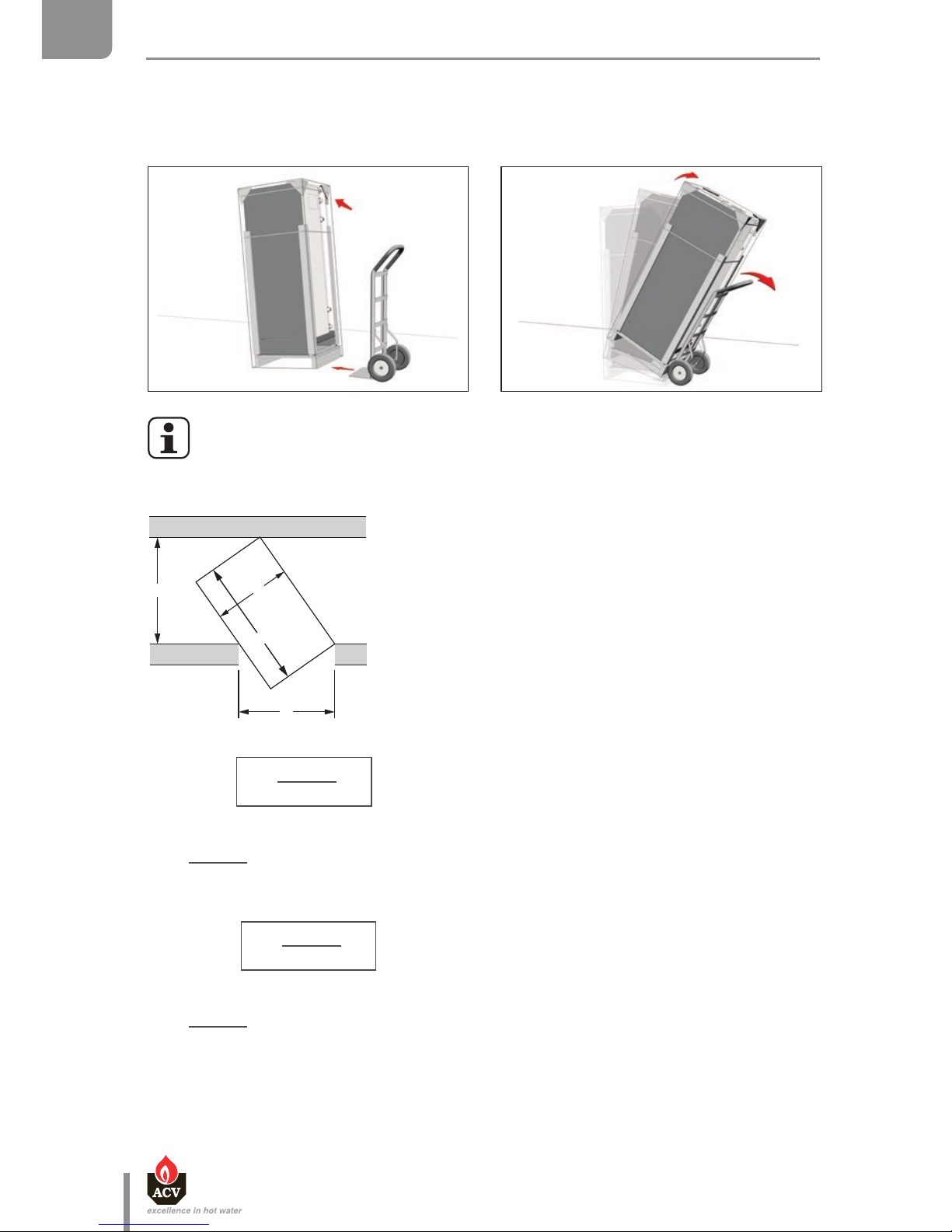
Move the boiler using a hand truck or a pallet truck.
Use a means of transport adapted to the boiler weight. See "Dimensions", page 26
Minimum width of the door and the hall necessary to pass the boiler
C
B
A
D
A = maximum boiler width
B = maximum boiler length
C = Door width
D = Hall width
Door height = std
Hall width :
C =
A
x B
D
Example of calculation to determine the minimum hall width, with a door width: D = 800 mm
C =
540
x 1000
= Hall width ≥ 675 mm
800
Door width:
D =
A
x B
C
Example of calculation to determine the minimum door width, with ahall width: D = 900 mm
D =
540
x 1000
= Hall width ≥ 600 mm
900
Page 37

SAFETY INSTRUCTIONS FOR THE INSTALLATION
General remarks
• The connections (electrical, flue pipe, hydraulic) must be carried out in accordance
with current standards and regulations in force.
• If the water drawing off point is far from the tank, installing an auxiliary DHW loop
can allow to get hot water more quickly at all times.
Essential recommendations for the correct operation of the appliance
• The boiler must be installed in a dry and protected area.
• Install the appliance to ensure easy access at all times.
• To avoid any risk of corrosion, connect the stainless steel DHW production tank
directly to the earth.
• Make sure to install a pressure reducing valve set at 4.5 bar if the mains supply
pressure is in excess of 6 bar.
• The DHW circuit must be fitted with an approved safety group, comprised of a 7
bar safety valve, a check valve and a shut-off valve.
• If works need to be performed (in the boiler room or close to the air vents), make
sure to turn off the boiler to prevent dust from entering and accumulating in the
boiler heating system.
Essential recommendations for safety
• Install the boiler on a base made of non-combustible materials.
• Make sure that all air vents are unobstructed at all times.
• A condensation outlet connected to the sewer must be fitted close to the boiler
to prevent the condensation products from the flue pipe from running into the
boiler.
• The horizontal flue pipes must be installed with a slight slope of 5 cm per meter,
so that the acid condensation water flows to a condensate recovery container and
does not damage the heating body.
• Do not store any corrosive products, paint, solvents, salts, chloride products and
other detergent products near the appliance.
• The flue pipe diameter must not be smaller than that of the boiler flue gas outlet
connection.
en
37
Heat Master TC : 6 64Y6800 • A
EN
FR
NL
ES
IT
DE
PL
RU
INSTALLATION
Page 38

• Hot water can cause scalding!
• In the event of small amounts of hot water repeatedly being drawn off, a
stratification effect can develop in the tank. The upper hot water layer may then
reach very high temperatures.
• ACV recommends using a pre-set thermostatic mixing valve in order to provide
hot water at a maximum of 60°C.
• Water heated to wash clothes, dishes and for other uses can cause serious burns.
• In order to avoid exposure to extremely hot water that can cause serious burns,
never leave children, old people, disabled or handicapped people in the bath
orshower alone.
• Never allow young children to turn on the hot water or fill their own bath.
• The temperature of the domestic hot water can be adjusted up to 90 °C in the
boiler. However, the temperature of the domestic hot water at the drawing off
point must comply with local regulations. (E.g. in Belgium, the maximum DHW
water temperature at a drawing off point must be 75°C for boilers < 70 kW).
• The risk of developing bacteria exists, including “Legionella pneumophila”,
ifaminimum temperature of 60°C is not maintained in both the DHW tank andthe
hot water distribution network.
Essential recommendations for the electrical safety
• Only an approved installer is authorized to carry out the electrical connections.
• Install a 2-way switch and a fuse or circuit breaker of the recommended rating
outside the appliance, so as to be able to shut power down when servicing the
appliance or before performing any operation on it.
• Isolate the external electrical supply of the appliance before performing any
operation on the electrical circuit.
• This appliance is not intended for use by persons (including children) with reduced
physical, sensory or mental capabilities, or lack of experience and knowledge,
unless supervised or unless they have been given instruction concerning the use
of the appliance by a person responsible for their safety.
en
38
Heat Master TC : 6 64Y6800 • A
EN
FR
NL
ES
IT
DE
PL
RU
INSTALLATION
Page 39

RECOMMENDATIONS FOR THE PREVENTION OF CORROSION AND
SCALING IN HEATING SYSTEMS
How oxygen and carbonates can affect the heating system
Oxygen and dissolved gasses in the water of the primary circuit contribute to the oxidation and the corrosion of the system components that are made of ordinary steel
(radiators, ...). The resulting sludge is then deposited in the boiler exchanger.
The combination of carbonates and carbon dioxide in the water results in the formation of scale
on the hot surfaces of the installation, including those of the boiler exchanger.
These deposits in the heat exchanger reduce the water ow rate and thermally insulate the exchange surfaces, which is likely to damage them.
Sources of oxygen and carbonates in the heating circuit
The primary circuit is a closed circuit; the water it contains is therefore isolated from the mains
water. When maintaining the system or lling up the circuit, water renewal results in the addition
of oxygen and carbonates in the primary circuit. The larger the water volume in the system, the
larger the addition.
Hydraulic components without an oxygen barrier (PE pipes and connections) admit oxygen into
the system.
Prevention Principles
1. Clean the existing system before installing a new boiler
- Before the system is lled, it must be cleaned in accordance with standard EN14336.
Chemical cleaning agents can be used.
- If the circuit is in bad condition, or the cleaning operation was not efficient, or the volume of
water in the installation is substantial (e.g. cascade system), it is recommended to separate
the boiler from the heating circuit using a plate-to-plate exchanger or equivalent. In that
case, it is recommended to install a hydrocyclone or magnetic filter on the installation side.
2. Limit the fill frequency
- Limit fill operations. In order to check the quantity of water that has been added into the
system, a water meter can be installed on the filling line of the primary circuit.
- Automatic filling systems are not recommended.
- If your installation requires frequent water refilling, make sure your system is free of water
leaks.
- Inhibitors may be used in accordance with standard EN 14868.
3. Limit the presence of oxygen and sludge in the water
- A deaerator (on the boiler flow line) combined with a dirt separator (upstream of the boiler)
must be installed according to the manufacturer's instructions.
- ACV recommends using additives that keep the oxygen in solution in the water, such as
Fernox (www.fernox.com) and Sentinel (www.sentinel-solutions.net) products.
- The additives must be used in accordance with the instructions issued by the manufacturer
of the water treatment product.
en
39
Heat Master TC : 6 64Y6800 • A
EN
FR
NL
ES
IT
DE
PL
RU
INSTALLATION
Page 40

4. Limit the carbonate concentration in the water
- The fill water must be softened if its hardness is higher than 20° fH (11,2° dH).
- Check regularly the water hardness and enter the values in the service log.
- Water hardness table :
Water hardness °fH °dH mmolCa(HCO3)2 / l
Very soft 0 - 7 0 - 3.9 0 - 0.7
Soft 7 - 15 3.9 - 8.4 0.7 - 1.5
Fairly hard 15 - 25 8.4 - 14 1.5 - 2.5
Hard 25 - 42 14 - 23.5 2.5 - 4.2
Very hard > 42 > 23.5 > 4.2
5. Control the water parameters
- In addition to the oxygen and the water hardness, other parameters of the water must be
checked.
- Treat the water if the measured values are outside the range.
Acidity 6,6 < pH < 8,5
Conductivity < 400 S/cm (at 25°C)
Chlorides < 125 mg/l
Iron < 0,5 mg/l
Copper < 0,1 mg/l
en
40
Heat Master TC : 6 64Y6800 • A
EN
FR
NL
ES
IT
DE
PL
RU
Page 41
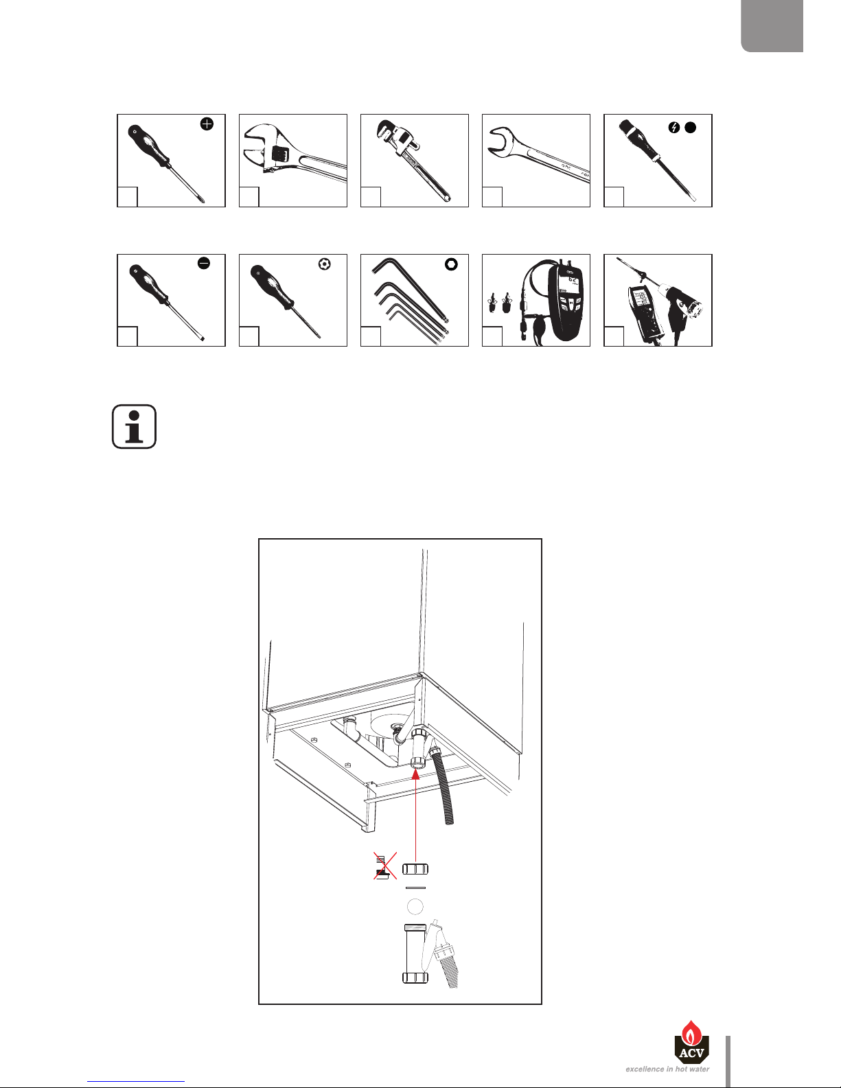
TOOLS REQUIRED FOR THE INSTALLATION
GAS
pressure
(mbar)
en
41
Heat Master TC : 6 64Y6800 • A
EN
FR
NL
ES
IT
DE
PL
RU
BOILER PREPARATION
Before placing the boiler in its nal position, install:
• The ball condensate trap
If you have selected an "Easy Fit" kit (HeatMaster® 25 / 35 / 45 TC), install it at the rear
of the boiler before placing the appliance in its final position.
Page 42
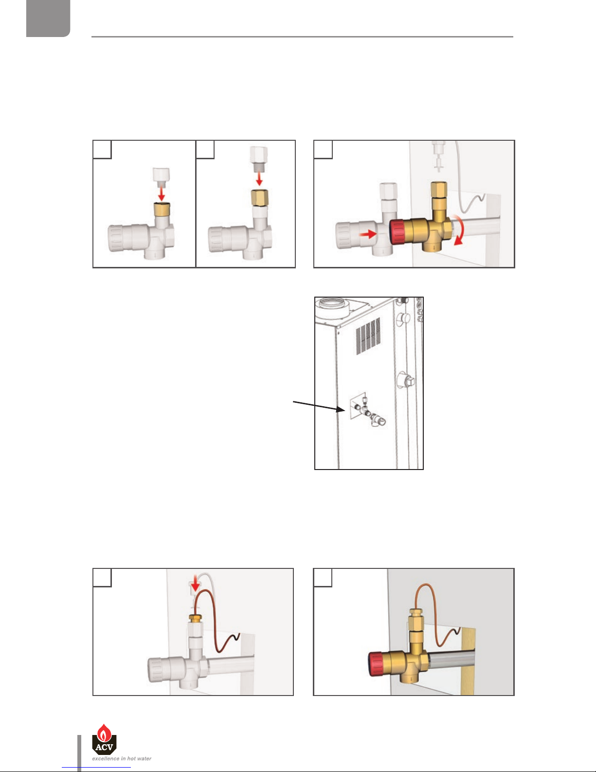
1 2 3
Mounting of the kit with T-coupling
(HM 120TC only)
en
42
Heat Master TC : 6 64Y6800 • A
EN
FR
NL
ES
IT
DE
PL
RU
INSTALLATION
BOILER PREPARATION
• The safety valve kit (HM TC equipped with a high eciency pump) :
T-coupling (HM 120 TC only)
Check valve
Primary circuit safety valve
4 5
• The pressure gauge sensor (front panel) into the pressure gauge connection of the safety
valve.
Page 43
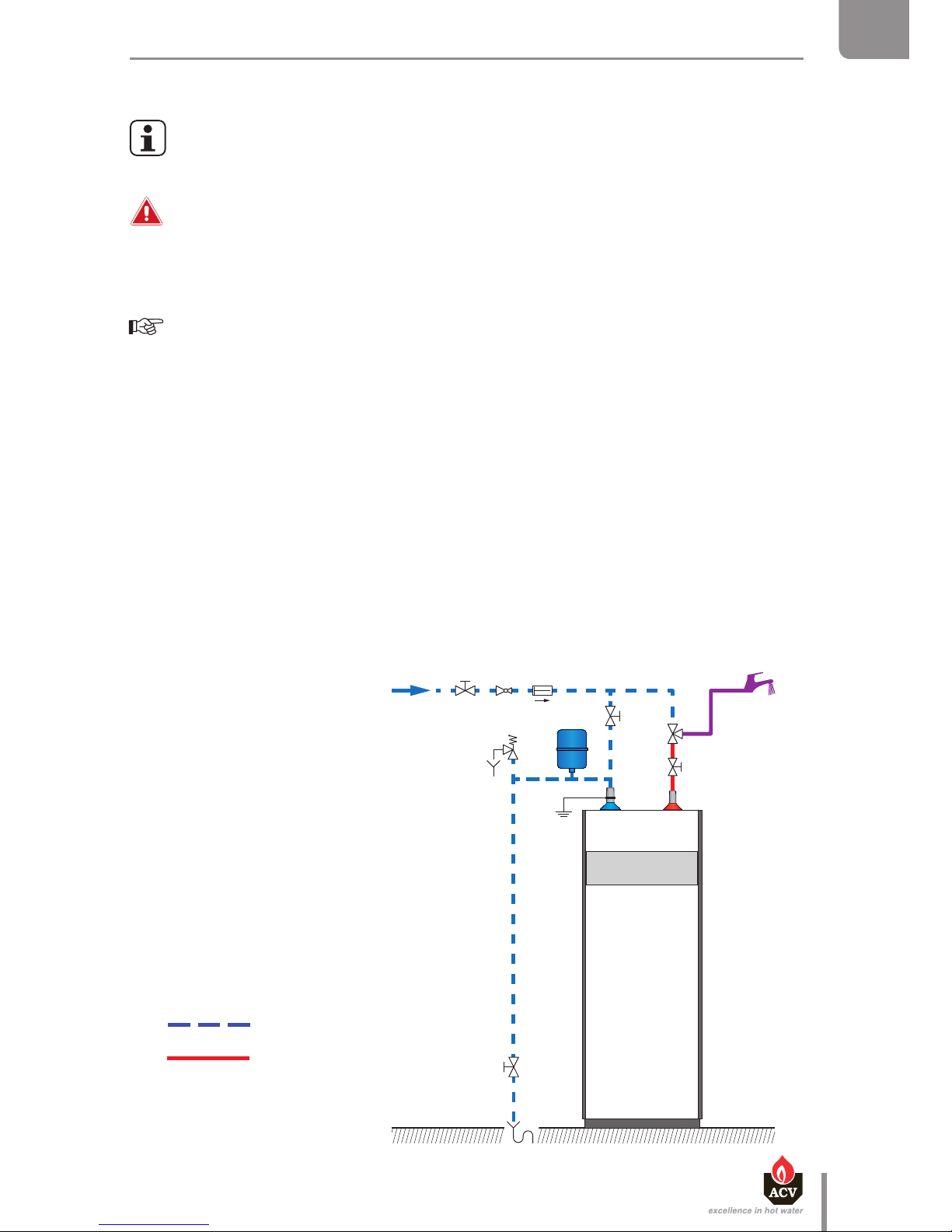
Typical installation
Description
1. Isolating valve
2. Pressure reducing valve
3. Check valve
4. DHW expansion vessel
5. Safety valve
6. Drain valve
7. Draw-off tap
8. Grounding
9. Thermostatic mixing valve
Cold water
Hot water
1 2 3
1
1
8
4
5
6
7
9
en
43
Heat Master TC : 6 64Y6800 • A
EN
FR
NL
ES
IT
DE
PL
RU
INSTALLATION
DHW CONNECTION
General remark
• The circuit illustrations are basic principle diagrams only.
Essential recommendation for safety
• The hot water output may reach temperatures in excess of 60°C, which can cause
scalding! It is therefore necessary to install a thermostatic mixing valve after the
appliance.
Essential recommendations for the correct operation of the appliance
• Flush the system before connecting the domestic hot water circuit. Refer to the
installation instructions.
• Make sure to install a pressure reducing valve set at 4.5 bar if the mains supply
pressure is in excess of 6 bar.
• The installation must be fitted with an approved safety group, comprised of a 7 bar
safety valve, a check valve and a shut-off valve.
• It is recommended to install an expansion vessel in the DHW circuit to prevent the
safety valve from opening constantly and reduce the water hammer effect in the
system.
• If the HeatMaster® 25, 35 or 45 TC is used as a domestic hot water preparation tank,
an expansion vessel of at least 16 liters must be fitted in the primary circuit (no
internal expansion vessel is fitted in the HeatMaster® 25, 35 and 45 TC).
Page 44
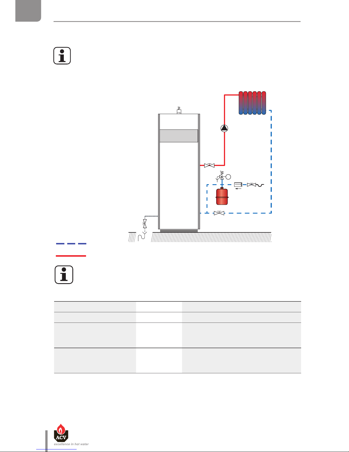
HEATING CONNECTION
Typical connection - high temperature
Description
1. Isolating valve
2. Heating pump
3. Filling valve
4. Safety valve
5. Expansion vessel
6. Drain valve
7. Air bleed valve
8. Check valve
1
1
7
2
4
5
6
3
Cold water
Hot water
8
en
44
Heat Master TC : 6 64Y6800 • A
EN
FR
NL
ES
IT
DE
PL
RU
INSTALLATION
Accessory Code Description
Room thermostat 10800018
High temperature kit DN 25
(HM 25 / 35 / 45 TC)
10800294 Includes a heating pump, two
isolating valves, a check valve and two
thermometers.
High temperature kit DN 32
(HM 70 / 85 / 120 TC)
10800296 Includes a heating pump, two
isolating valves, a check valve and two
thermometers.
Optional accessories to control a regular high temperature heating circuit.
For more information, refer to the System Control manual provided with the
boiler.
For the position and dimension of connections, please refer to "Dimensions", page 26
HEATING CONNECTION
Page 45
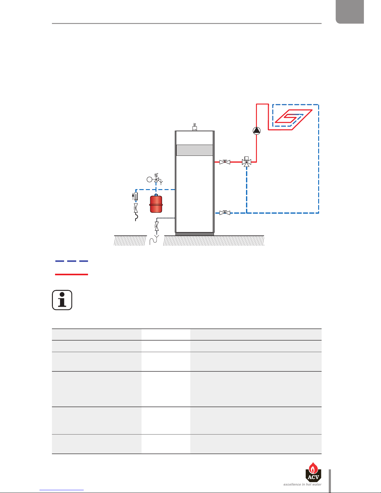
HEATING CONNECTION
Typical connection - high temperature
Description
1. Isolating valve
2. Heating pump
3. Filling valve
4. Safety valve
5. Expansion vessel
6. Drain valve
7. Air bleed valve
8. Check valve
Typical connection - low temperature
Description
1. Isolating valve
2. 3-way mixing valve
3. Heating pump
4. Safety valve
5. Filling valve
6. Expansion vessel
7. Drain valve
8. Air bleed valve
9. Check valve
1
1
7
2
4
5
6
3
1
1
2
3
4
5
6
7
8
Cold water
Hot water
8
9
Cold water
Hot water
en
45
Heat Master TC : 6 64Y6800 • A
EN
FR
NL
ES
IT
DE
PL
RU
INSTALLATION
Accessory Code Description
Room thermostat 10800018
Contact thermostat 10510900 Mandatory to protect all oor heating
circuits.
Low temperature kit DN 25
(HM 25 / 35 / 45 TC)
10800295 Includes a heating pump, two isolating
valves, a check valve, two thermometers,
a 3-way valve with built-in bypass and a
servomotor.
Low temperature kit DN 32
(HM 70 / 85 / 120 TC)
10800297 Includes a heating pump, two isolating
valves, a check valve, two thermometers and
a 3-way valve with built-in bypass.
Servomotor 10800199 Motor for the 3-way valve provided with the
low temperature kit.
Optional accessories to control a regular low temperature heating circuit.
For more information, refer to the System Control manual provided with the
boiler.
Page 46
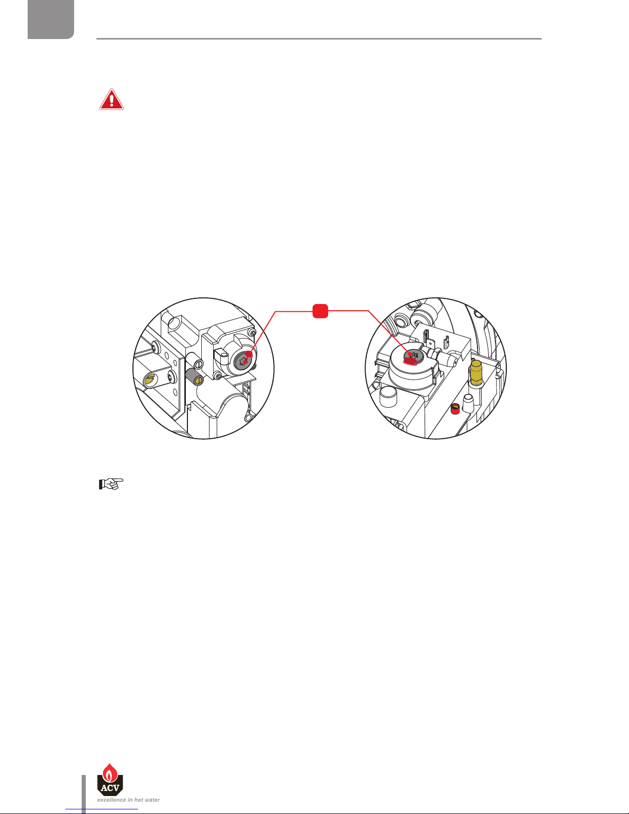
GAS CONNECTION
Essential recommendations for safety
• The gas connection must comply with all applicable standards [e.g. in Belgium:
NBN D51-003].
• The gas burners are factory preset for use with natural gas [equivalent to G20].
• The natural gas to propane conversion or the reverse is not authorized in certain
countries such as Belgium. Refer to the table of gas categories in the technical
characteristics of this manual.
• The CO
2
, gas flow rate, air flow rate and air/gas supply parameters are factory-
preset and may not be modified in Belgium, except for type I 2E(R)B boilers.
• Do not change the OFFSET (A) setting of the gas valve: it is factory-preset and
sealed.
Essential recommendations for the correct operation of the appliance
• Refer to th e technical char acteristic s of this manual or to the b urner docume ntation
to know the connection diameters.
• Bleed the gas duct and check thoroughly if all the boiler tubes, both internal and
external, are tight.
• Check the system gas pressure. Refer to the table containing all relevant data in
the section "Technical characteristics".
• Check the boiler electrical connection, the boiler room air vent system, the
tightness of flue gas outlet pipes and of the burner chamber plate.
• Control the gas pressure and consumption at appliance start up.
• Check the boiler CO
2
adjustment (refer to the adjustment procedure and the
technical data).
en
46
Heat Master TC : 6 64Y6800 • A
EN
FR
NL
ES
IT
DE
PL
RU
INSTALLATION
HeatMaster® 120 TC only
A
Page 47
1
2
5
6
3
4
en
47
Heat Master TC : 6 64Y6800 • A
EN
FR
NL
ES
IT
DE
PL
RU
INSTALLATION
CONVERSION TO PROPANE HM 85 / 120 TC
According to the indication on the type plate, the boiler is factory preset to operate
with natural gas (G20/G25). Converting the boiler to propane is done through the
addition of a cover plate and adjustments.
Set-up conditions
• External power supply isolated
• Gas supply closed
• Upper panel of the boiler removed
Procedure of cover plate addition
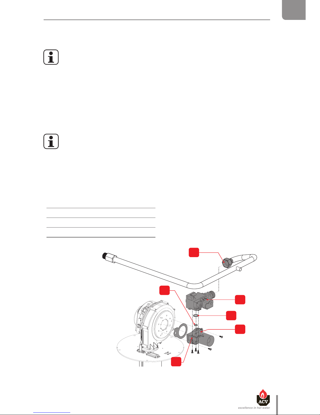
To know where the components are located on the HM 120 TC, refer to figure on page 13.
1. Unscrew the gas tube pipe (1).
2. Remove the plug from the gas valve (2).
3. Disconnect the air inlet.
4. Remove the gas valve/venturi assembly (3) by releasing two screws. Retain the screws for
reinstallation.
Cover plate Ø
Gas type HM 85 TC HM 120 TC
G20/25
10.7
G31 6.8 6.7
Page 48
en
48
Heat Master TC : 6 64Y6800 • A
EN
FR
NL
ES
IT
DE
PL
RU
INSTALLATION
GAS CIRCUIT CONNECTION
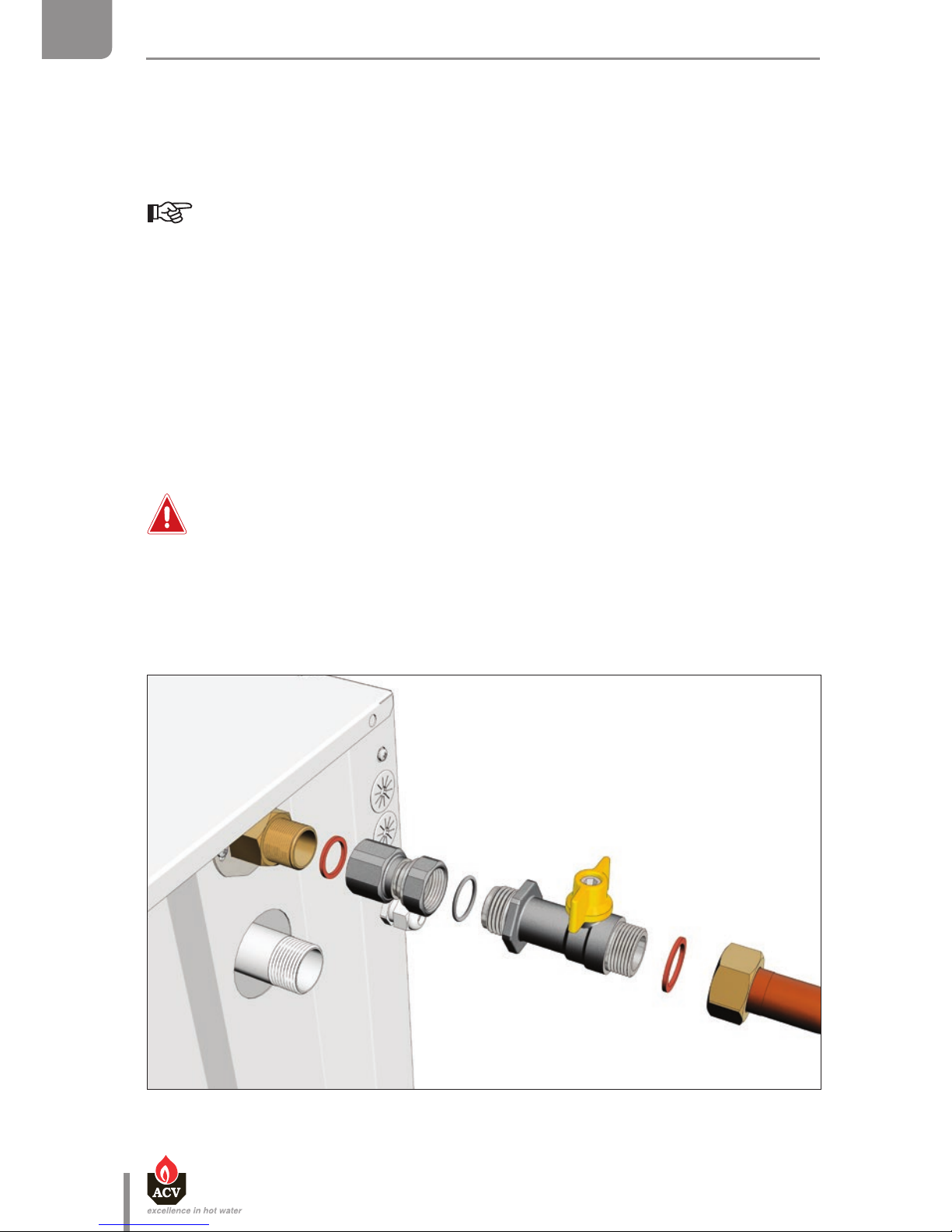
5. Remove the gas valve from the venturi (4) by releasing 3 screws. Retain the screws for reinstallation.
6. Install the cover plate (6) in the center of the O-ring (5).
Make sure you position the O-ring correctly.
7. Reassemble the gas valve/venturi assembly, following the same procedure in reverse order, and
tighten the 3 gas valve screws and the 2 venturi screws with a torque of 3.5 to 4 Nm.
8. Stick the sticker provided with the conversion kit on the boiler and check the box to indicate the
type of gas to be now used with the boiler.
Follow-on tasks
• Adjust parameters 22 to 28 of MCBA (See the System Control manual)
• Carry out the CO
2
adjustment, (see "Checking and adjusting the burner")
Before carrying out the CO
2
adjustment, it is important to adjust the fan speed
parameters (See the System Control manual of the boiler).
Page 49
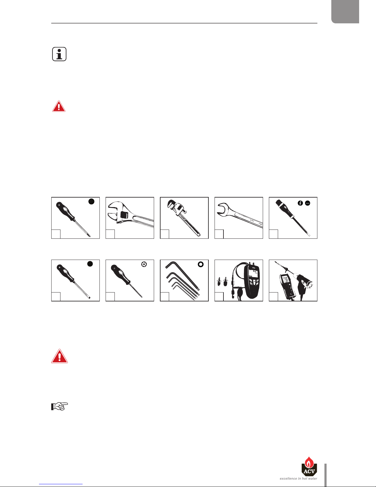
SAFETY INSTRUCTIONS FOR STARTING UP
General remark
• In normal operation, the burner starts automatically as soon as the boiler
temperature drops below the preset temperature.
Essential recommendations for safety
• The components inside the control panel may only be accessed by an approved
installer.
• Set the water temperature in accordance with usage and local plumbing codes.
en
49
Heat Master TC : 6 64Y6800 • A
EN
FR
NL
ES
IT
DE
PL
RU
STARTING UP
CHECKS BEFORE STARTING UP
Essential recommendation for safety
• Check the tightness of the flue pipe connections.
Essential recommendation for the correct operation of the appliance
• Control the tightness of the hydraulic circuit connections.
TOOLS REQUIRED FOR STARTING UP
GAS
pressure
(mbar)
Page 50
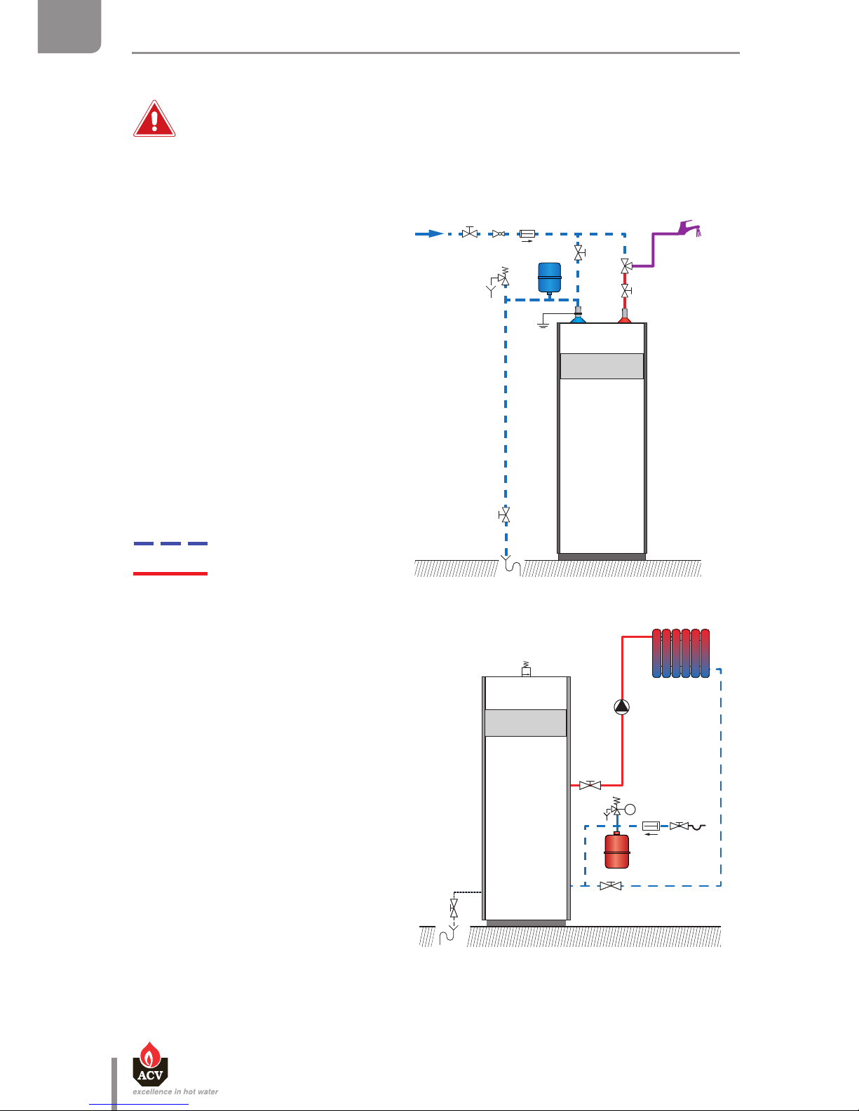
FILLING THE SYSTEM
First put the DHW tank under pressure before pressurizing the heating (primary)
circuit.
Filling the domestic hot water circuit
1. Open the isolating valves (1) and the
draw-o tap (2).
2. Once the water flow rate has stabilized
and the air is totally evacuated from
the system, close the draw-off tap (2).
3. Check all the connections for leaks.
Filling of the heating circuit
1. Open the isolating valves (1).
2. Make sure that the drain valve (3) is
tightly closed.
3. Open the lling valve (2).
4. Open the air bleed valve (4).
5. Once the system is bled from air,
bring the pressure to the static
pressure + 0.5 bar: 1.5 bar = 10m - 2
bar = 15m
Cold water
Hot water
1
1
1
2
1
1
2
3
4
en
50
Heat Master TC : 6 64Y6800 • A
EN
FR
NL
ES
IT
DE
PL
RU
STARTING UP
Page 51

en
51
Heat Master TC : 6 64Y6800 • A
EN
FR
NL
ES
IT
DE
PL
RU
STARTING UP
STARTING UP THE BOILER
Set-up conditions
• All connections made
• Gas conversion carried out as required
• Power supply
• Gas supply open
• DHW and heating circuits full of water
Procedure
1. Place the ON/OFF master switch on the ON position ( ).
2. If a room thermostat is installed, possibly increase the temperature set-point to generate a
demand.
If the boiler charging pump does not work, the boiler can be damaged and its life
reduced.
3. Check with your hand (pump vibrations) that the charging pump is not blocked and unblock
it if required.
On the HM TC equipped with a high efficiency charging pump, a fault code "b 26"
shows on the control panel display. Refer to the System Control manual provided with
the boiler.
4. Checking and adjusting the burner (see “Checking and adjusting the burner”, page 52).
5. After 5 minutes of operation, bleed the heating circuit until all air is evacuated and restore a
1.5 bar pressure.
6. Bleed the central heating circuit once again and top it up with water to get the required
pressure, if necessary.
7. Make sure that the central heating system is properly balanced and, if needed, adjust the
valves to prevent certain circuits or radiators from getting a flow rate that is far above or
below the set rate.
Page 52
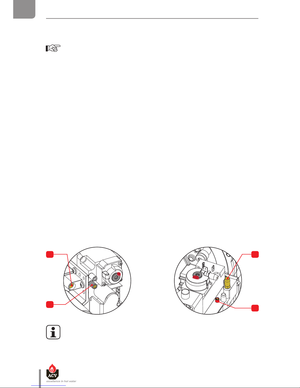
2
1
1
2
en
52
Heat Master TC : 6 64Y6800 • A
EN
FR
NL
ES
IT
DE
PL
RU
STARTING UP
CHECKING AND ADJUSTING THE BURNER
When the burner operates at full power, the CO2 rate must be within the limits mentioned
in the technical characteristics, (see "Combustion characteristics", page 18).
Set-up conditions
• Operating boiler
Check procedure
1. Check if the MCBA parameters are set to meet the user's requirements (see "Parameter
setting", page 7), and change them if required.
2. Put the boiler to maximum power mode (Refer to the System Control manual provided with
the boiler).
3. Using a pressure tester, check that the dynamic gas pressure at the gas valve (2) is at least 18
mbar.
4. Allow the appliance to heat for a few minutes until it reaches at least 60°C.
5. Measure the burner combustion by placing the flue gas analyzer probe in the measurement
unit port on the flue pipe and compare the CO and CO
2
values displayed with those indicated
in the combustion characteristics table.
6. If the CO
2
value differs by more than 0.3%, carry out the adjustment mentioned in the
procedure below.
7. Then put the boiler to the minimum power mode (Refer to the System Control manual
provided with the boiler). Allow the boiler to stabilize for a few minutes.
8. Measure the CO
2
level. It must be equal to the value at full power, or lower than that value
by 0.5% maximum. If there is a significant deviation, please contact ACV's maintenance
department.
CO2 adjustment procedure
To adjust the CO2 rate, rotate the venturi screw (1) :
• to the left (counterclockwise) to increase the CO
2.
rate.
• to the right (clockwise) to decrease the CO
2.
rate.
The CO2 adjustment screw (1) of the HM 120 TC is a worm screw, whose rotation in a
direction causes the CO2 rate to cyclically increase to the maximum, then decrease to
the minimum, then increase again, and so on. To adjust, monitor the value change on
the analyzer to determine whether the rotation in the selected direction causes the
CO2 value to increase or decrease.
HeatMaster® 120 TC only
Page 53

SAFETY INSTRUCTIONS FOR THE BOILER MAINTENANCE
Essential recommendation for the electrical safety
• Isolate the external power supply of the appliance before performing any
operation, unless it is required to take measurements or perform system setup.
Essential recommendations for safety
• Water flowing out of the drain valve may be extremely hot and could cause severe
scalding.
• Check the tightness of the flue pipe connections.
Essential recommendations for the correct operation of the appliance
• It is recommended to have the boiler and the burner serviced at least once a year or
every 1,500 hours. More frequent servicing may be required depending on boiler
use. Please consult your installer for advice.
• The boiler and burner maintenance will be carried out by a qualified engineer, and
the defective parts may only be replaced by genuine factory parts.
• Control the tightness of the hydraulic circuit connections.
• Make sure to replace the gaskets of the removed items before reinstalling them.
en
53
Heat Master TC : 6 64Y6800 • A
EN
FR
NL
ES
IT
DE
PL
RU
MAINTENANCE
Page 54
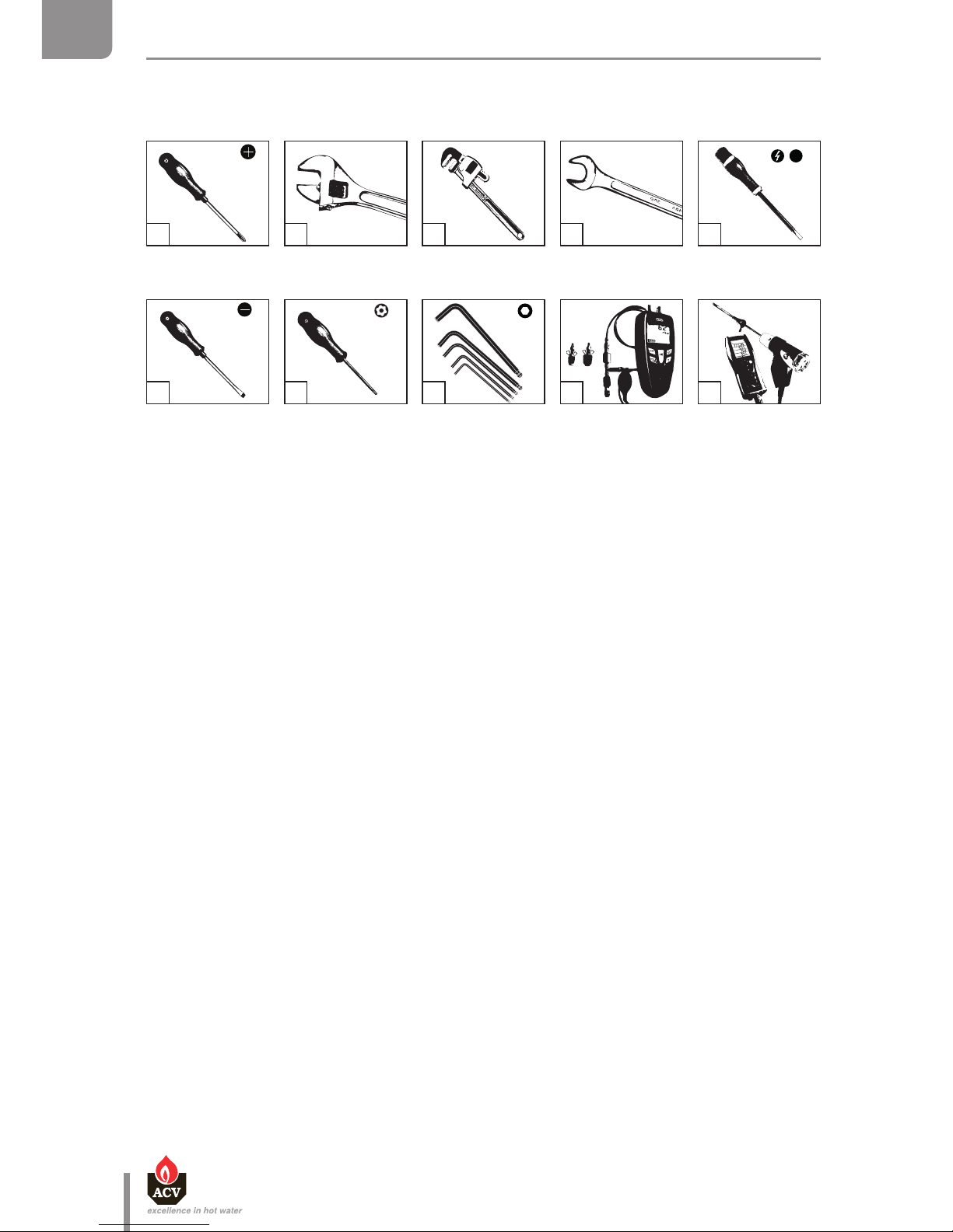
en
54
Heat Master TC : 6 64Y6800 • A
EN
FR
NL
ES
IT
DE
PL
RU
MAINTENANCE
TOOLS REQUIRED FOR MAINTENANCE
BOILER SHUT DOWN FOR MAINTENANCE
1. Switch the boiler off using the ON/OFF master switch and isolate the external power supply.
2. Close the gas supply valve of the boiler.
GAS
pressure
(mbar)
Page 55
en
55
Heat Master TC : 6 64Y6800 • A
EN
FR
NL
ES
IT
DE
PL
RU
MAINTENANCE
PERIODIC BOILER MAINTENANCE TASKS
Tasks
Frequency
Periodic
inspection
1 year 2 years
End-user Professional
1. Make sure that the system water pressure is at least
1 bar when cold. Top up the system if necessary,
adding small quantities of water at a time. In case of
repeated lls, call your installer.
X X
2. Check that there is no water on the oor in front of
the boiler. Call your installer if there is.
X X
3. Check that no error code is displayed on the control
panel. Call your installer if necessary.
X X
4. Check that all gas, hydraulic and electrical
connections are correctly fastened and tight.
X
5. Check the ue gas exhaust: correct fastening,
correct installation, no leaks or clogging.
X
6. Check that there is no discolored or cracked area on
the burner chamber plate .
X
7. Check the combustion parameters (CO and CO
2
),
see "Checking and adjusting the burner", page 52
X
8. Check visually the heating body: no evidence of
corrosion, soot deposits or damages. Carry out all
required cleaning tasks, repairs and replacements
that might be required.
X
9. Check the electrode, see "Removal, check and
reinstallation of the burner electrode", page 56
X
10. Remove the burner and clean the exchanger, see
"Removal and reinstallation of the burner", page
57 and "Cleaning the exchanger", page 58.
X
11. Remove and clean the condensate recovery dish,
see "Removing and cleaning the condensate
recovery dish", page 59
X
Page 56
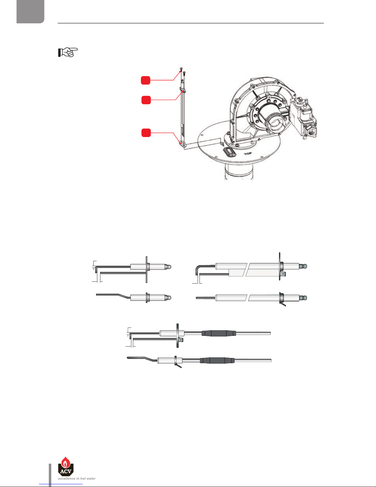
2
3
1
3 mm
5 mm
3 mm
3 mm
3 mm
HeatMaster® 25 / 35 TC HeatMaster® 70 / 85 / 120 TC
HeatMaster® 45 TC
en
56
Heat Master TC : 6 64Y6800 • A
EN
FR
NL
ES
IT
DE
PL
RU
MAINTENANCE
REMOVAL, CHECK AND REINSTALLATION OF THE BURNER ELECTRODE
Set-up conditions
• Boiler shut down
• External power supply isolated
• Gas supply closed
Removal procedure
1. Open the upper front panel of the boiler and remove the upper panel, located on top of the boiler
by releasing two cross-head screws.
2. Unplug the electrode ignition cable.
3. Disconnect the electrode grounding cable.
4. Remove two mounting screws (1) and retain them for reinstallation.
5. Remove the electrode (2).
6. Check the correct alignment of the electrode ends and that the gap corresponds to the values
indicated in the figure below.
7. Check the gap between the electrode and the burner tube, see "Removal and reinstallation of the
burner", page 57.
Reinstallation procedure
1. Reinstall a new gasket (3).
2. Reinstall the electrode (2) using the two screws (1), torque them at 3 to 3.5 Nm, making sure that
the lock washer is correctly installed between the grounding cable and the electrode.
3. Reconnect the electrode grounding cable and the ignition cable.
It is recommended to remove the electrode before removing the burner in order to
prevent the insulation block from being damaged when lifting the burner.
Page 57
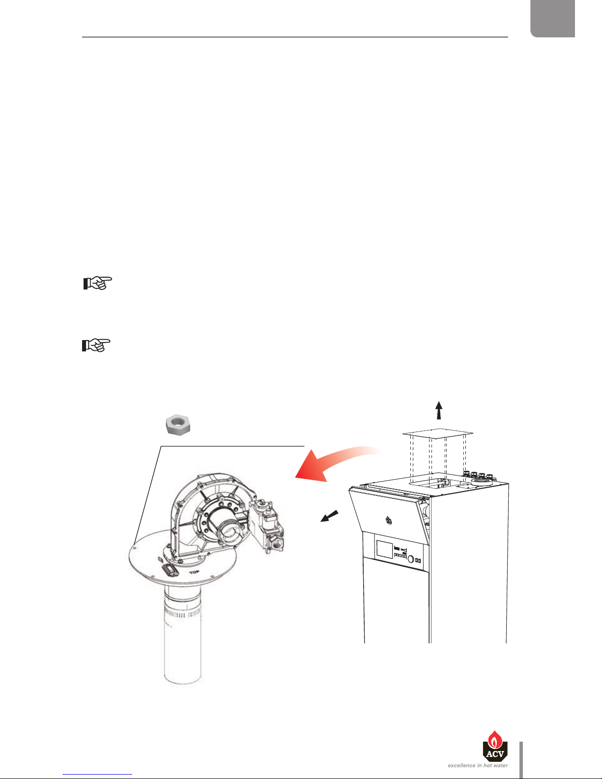
X 4 (HM 25 / 35 / 45 TC)
X 5 (HM 70 / 85 / 120 TC)
en
57
Heat Master TC : 6 64Y6800 • A
EN
FR
NL
ES
IT
DE
PL
RU
MAINTENANCE
REMOVAL AND REINSTALLATION OF THE BURNER
Set-up conditions
• Boiler shut down
• External power supply isolated
• Gas supply closed
• Electrode removed
• Front and upper panels open
Removal procedure
1. Disconnect the plug(s) from the motor side and the plug from the gas valve side
2. Disconnect the pressure hose and the air tube.
3. Unscrew the gas pipe connection.
4. Using an open-end spanner, release the burner retaining bolts.
Make sure the electrode is removed before lifting the burner, or the insulation block
may be damaged.
5. Lift the burner, fan and gas valve assembly, rotating it slightly to get it out of the exchanger.
Try not to damage the burner insulation in the exchanger, nor the burner chamber
plate.
Page 58

en
58
Heat Master TC : 6 64Y6800 • A
EN
FR
NL
ES
IT
DE
PL
RU
MAINTENANCE
CLEANING THE EXCHANGER
Set-up conditions
• Boiler shut down
• External power supply isolated
• Gas supply closed
• Burner removed i.a.w. procedure "Removal and reinstallation of the burner", page 57.
• Front and upper panels open
Procedure
1. Remove the burner insulation.
2. Vacuum clean the chamber.
3. Pour some water in the chamber to flush away any foreign deposits that may be present in the flue
pipes.
4. In the case of HM TC that are not equipped with a recirculation copper tube, access the condensate
ball trap by opening the boiler base, then remove and clean the condensate trap. Reinstall the
condensate trap, refer to "Boiler preparation", page 41.
Follow-on tasks
1. Reinstall the burner according to procedure "Removal and reinstallation of the burner", page
57
2. Reinstall the electrode according to procedure "Removal, check and reinstallation of the burner
electrode", page 56.
3. In the case of HM TC equipped with recirculation copper tube, remove and clean the condensate
recovery tray and the condensate trap according to procedure on next page.
4. In the case of HM TC that are not equipped with a recirculation copper tube, restart the boiler in
accordance with procedure "Restarting after maintenance", page 61
6. Check the insulation block condition and replace it if it is cracked or broken.
Check that there is no discolored or cracked area on the burner chamber plate.
If it is the case, contact ACV's maintenance department.
7. Remove and replace the seals.
8. While the burner is removed, temporarily install the electrode in its housing and check that the
gap between the electrode and the burner tube is approximately 5 mm.
9. Remove the electrode and retain for reinstallation.
10. If required, clean the exchanger, see "Cleaning the exchanger", page 58
Reinstallation procedure
1. Reinstall the burner, making sure that the hole to fit the electrode in the burner chamber plate and
the hole in the insulation block are aligned.
2. Install the retaining nuts and fasten them in a crosswise pattern with a tightening torque of 5 to 6
Nm.
3. Reconnect the gas pipe.
4. Reconnect the air tube and the pressure hose.
5. Connect the plug(s) on the motor side and on the gas valve side.
Follow-on tasks
1. Reinstall the electrode, see "Removal, check and reinstallation of the burner electrode", page 56
Page 59
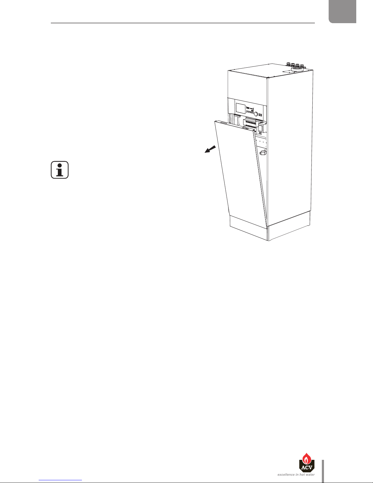
en
59
Heat Master TC : 6 64Y6800 • A
EN
FR
NL
ES
IT
DE
PL
RU
MAINTENANCE
REMOVING AND CLEANING THE CONDENSATE RECOVERY DISH
HM TC EQUIPPED WITH A RECIRCULATION COPPER TUBE
Set-up conditions
• Boiler shut down.
• External power supply isolated.
• Gas supply closed.
• Primary circuit of boiler drained, see "Draining
the boiler", page 60.
• Hydraulic circuits (DHW and primary) isolated
• Lower front panel and base open
Procedure
Make sure that the primary circuit of the
boiler has been completely drained of
water before starting the procedure.
1. Remove and clean the ball condensate trap.
2. Disconnect the lower couplings.
3. Disconnect the flue gas sensor.
4. Remove the flue pipe elbow.
5. Disconnect the copper tube located between
the charging pump and the condensate recovery
dish.
6. Remove the condensate recovery dish and clean it.
7. Replace the condensate recovery dish gaskets
8. Reinstall the condensate recovery dish and reconnect all the previously disconnected items, in
the oposite order as that mentioned in steps 2 to 5. Make sure to replace the seals and gaskets as
required.
Follow-up tasks
1. Reinstall the condensate trap, see "Boiler preparation", page 41
2. Restart the boiler according to procedure, "Restarting after maintenance", page 61
Page 60
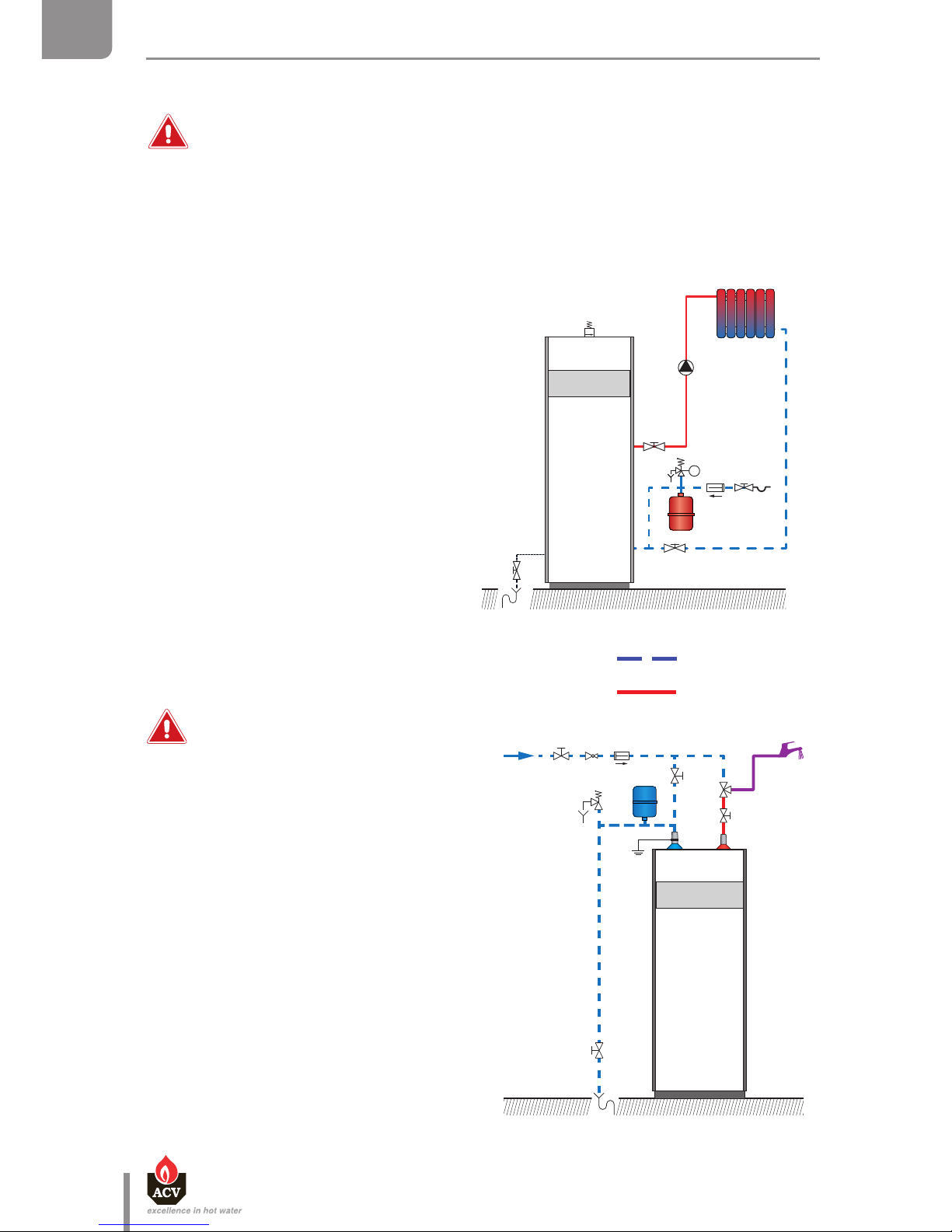
DRAINING THE BOILER
Before draining the DHW tank, drain the heating (primary) circuit or bring its pressure
to 0 bar.
Water flowing out of the drain valve may be extremely hot and could cause severe
scalding. Keep people away from the hot water discharge.
Set-up conditions
• Boiler switched o using the ON/OFF
master switch
• External power supply isolated
• Fuel/gas supply closed
Heating circuit draining procedure
1. Close the isolating valves (1).
2. Connect the drain valve (2) to the sewer
with a hose.
3. Open the drain valve (2) to empty the
heating circuit of the boiler.
4. Open the circuit air bleed valve (3) to
accelerate the draining process.
5. Close the drain valve (2) and the air bleed
valve (3) once the heating circuit of the
boiler is empty.
DHW circuit draining procedure
Before draining the DHW tank, make
sure that the heating (primary) circuit
pressure is null.
1. Open fully a draw-off tap (3) for about 60
minutes to make sure that the DHW tank
has cooled down.
2. Close the isolating valves (1).
3. Connect the drain valve (2) to the sewer
with a hose.
4. Open the drain valve (2) and drain the
DHW tank water to the sewer.
5. Open the draw-off tap (3) to accelerate the
draining process. If it is located lower than
the tank connection, open a draw-off tap
located higher in the system.
6. Close the drain valve (2) and the draw-off
tap (3) once the DHW tank of the boiler is
empty.
Cold water
Hot water
1
1
2
3
1
1
2
3
en
60
Heat Master TC : 6 64Y6800 • A
EN
FR
NL
ES
IT
DE
PL
RU
MAINTENANCE
Page 61

en
61
Heat Master TC : 6 64Y6800 • A
EN
FR
NL
ES
IT
DE
PL
RU
MAINTENANCE
RESTARTING AFTER MAINTENANCE
Set-up conditions
• All removed components reinstalled
• All connections made
• Power supply
• Gas supply open
• DHW and heating circuits full of water
Procedure
1. Switch the appliance on using the ON/OFF master switch.
2. Set the appliance at maximum power and check the absence of burned gas leaks.
3. Check the correct operation of the charging pump.
4. Check the gas pressure and CO
2
adjustment in accordance with procedure "Checking and
adjusting the burner", page 52.
Page 62
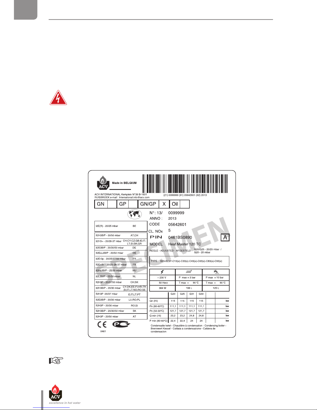
en
62
Heat Master TC : 6 64Y6800 • A
EN
FR
NL
ES
IT
DE
PL
RU
MAINTENANCE
The part number (Code) and serial number (N°) of the appliance are indicated on its
rating plate and must be provided to ACV in case of warranty claim. Failure to do so
will make the claim void.
SPECIMEN
Boiler Marking
To access the type plate, turn off the boiler and isolate the external power supply.
Location:
HM 25 / 35 / 45 TC: Upper section of the right side panel, inside the boiler. Release two upper
fasteners to open the upper panel.
HM 70 / 85 / 120 TC : Lower section of the right side panel, inside the boiler. Release two front
fasteners to open the lower panel.
IN CASE OF PROBLEM...
In case or problem, refer rst to the "System Control Manual" provided with the boiler. A list of blockage
and error codes is provided to help you solve specic issues.
If no solution can be found, please contact your ACV representative and communicate the Article
Number and Serial number of the appliance that can be found on the boiler type plate.
Page 63
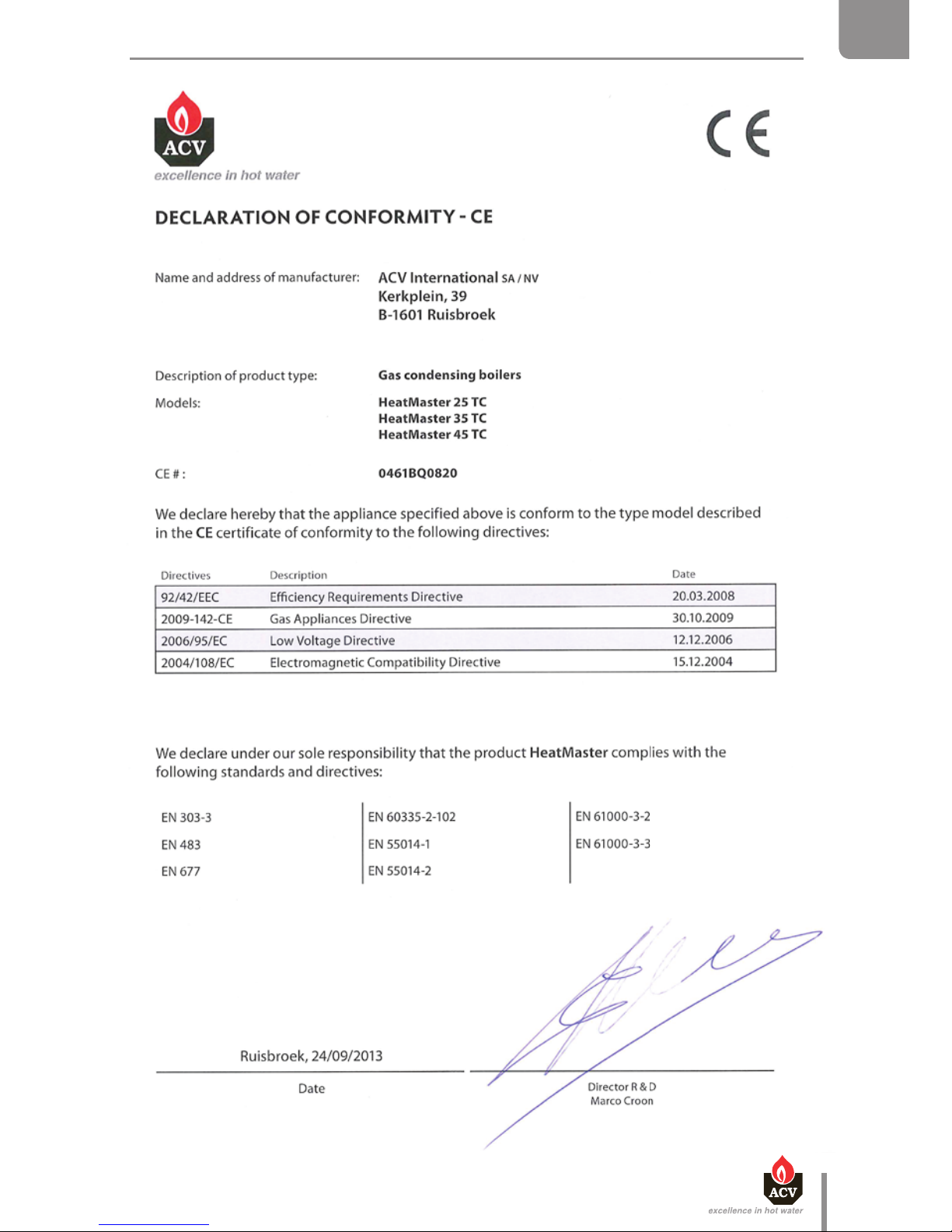
en
63
Heat Master TC : 6 64Y6800 • A
EN
FR
NL
ES
IT
DE
PL
RU
DECLARATION OF CONFORMITY EC
Page 64
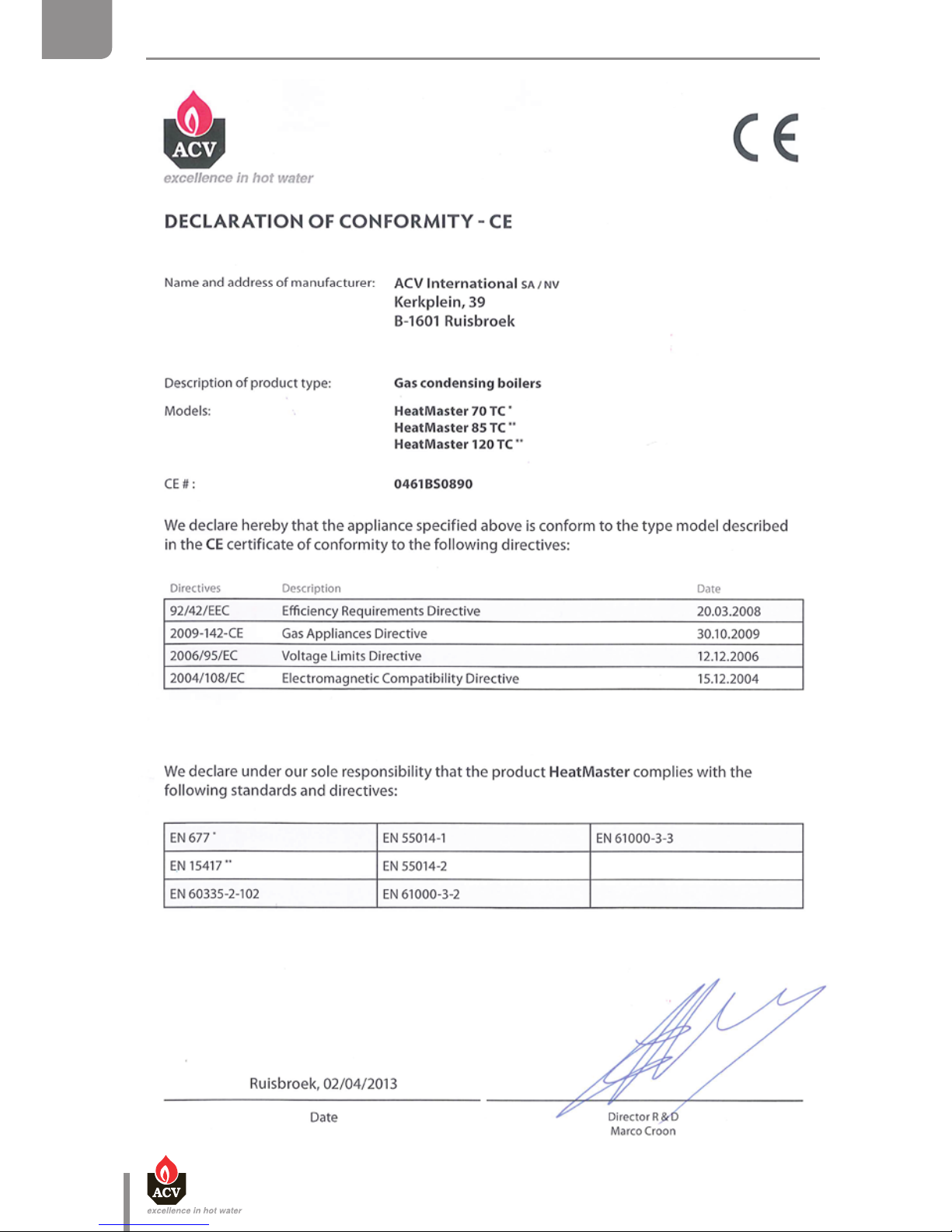
en
64
Heat Master TC : 6 64Y6800 • A
EN
FR
NL
ES
IT
DE
PL
RU
DECLARATION OF CONFORMITY - EC
Page 65

en
65
Heat Master TC : 6 64Y6800 • A
EN
FR
NL
ES
IT
DE
PL
RU
Page 66

en
66
Heat Master TC : 6 64Y6800 • A
EN
FR
NL
ES
IT
DE
PL
RU
Page 67

en
67
Heat Master TC : 6 64Y6800 • A
EN
FR
NL
ES
IT
DE
PL
RU
Page 68
MARKINGS LABELS
en
68
Heat Master TC : 6 64Y6800 • A
EN
FR
NL
ES
IT
DE
PL
RU
 Loading...